Professional Antennas for the Amateur
|
|
|
- Carol Patterson
- 5 years ago
- Views:
Transcription

1 HEATH TECH INC. High Sierra AntennAs HS-1800/Pro Professional Antennas for the Amateur
2 H IGH SIE R R A A NT E NNAS HS-1800/Pro Instruction Manual Heath Tech Inc. P.O. Box 2389 Nevada City, CA 95949
3 Table of Contents OVERVIEW... 1 MAINTENANCE... 3 INSTALLATION... 5 THE FIRST STEP IS TO UNPACK THE BOX... 5 INSTALLING THE CONTROL BOX THE ALL IMPORTANT GROUND CONNECTION UNIVERSAL MOUNTING BRACKET AND HOW TO INSTALL IT RF FILTER ASSEMBLY VEHICLE INSTALLATION BASE INSTALLATION NO MATTER WHERE YOU INSTALL THE ANTENNA, HERE ARE SOME THINGS TO KEEP IN MIND OPERATION OF THE ANTENNA THE UPS AND DOWNS OF THE ANTENNA.. 29 TROUBLESHOOTING, QUESTIONS AND ANSWERS WARRANTY INDEX... 35


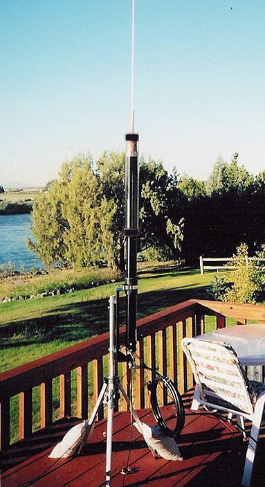
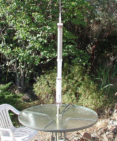
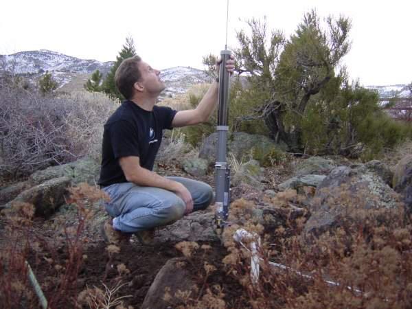
4 Chapter 1 Overview Please don t call it a screwdriver antenna! And, do read this manual. C ongratulations on your purchase of the finest continuous coverage motorized antenna. The new Pro version has several improvements over previous models. The major improvement is our new motor. For years High Sierra has manufactured its own motors. The new Black Hawk Motor is quantum leap forward. The new Black Hawk Motor is all metal. It has a very smooth operation do to its bearings. It is also very, very quiet. When the voltage is removed, this motor stops instantly. You can hear, see and even feel the difference. Parts for our antennas are manufactured using state of the art computer controller equipment. Because of that equipment, we can turn out large quantities to precision standards. 1

5 Installing an HF motorized antenna system is very different from a VHF or UHF antenna. A good grounding system, counterpoise or radials is absolutely essential. Tests with ohmmeters will likely provide misleading information. Antenna analyzers can give incorrect or false information. You should use the transceiver and its built-in SWR meter. Field strength meters may also be used. Keep in mind that it is very possible to have a high SWR and greater field strength with a properly installed and properly tuned system. For example, many antennas can have a 50 ohm impedance with a corresponding low SWR. But, they are very inefficient as radiators. They have a low SWR but don t radiate very well. A low SWR is not the goal. A strong signal is the goal. So, read the manual, follow the instructions and do the maintenance. You will be very happy with the performance of your High Sierra Antenna. If you have some questions, please try to find the answers in the manual first. There is a troubleshooting section and an index. If you can t find the answers, please do send an from the website at using the contact us box. Please do not call our 888 order line for technical support. Here are some things to keep in mind: Use the transceiver s built-in SWR meter to tune the antenna. We do not recommend the use of antenna analyzers or ohmmeters. You ll be using a transceiver to transmit not an analyzer or ohmmeter. An SWR of less than 2:1 is good. A lower SWR reading will not result in improved performance. In others words, when the antenna system has achieved an SWR of 2:1 or less you can stop. There is no reason for you to seek an SWR that is lower. 2

6 Chapter 2 Maintenance High Sierra Antennas has learned over the years that good maintenance is the key to good performance. That s why we are discussing maintenance even before installation of the system R outine maintenance includes doing the following items: 1. At least twice each year, remove the eight screws from the bottom of the antenna. Remove the large brass insert. Apply a liberal mount of an antioxidant to the inside (bottom) of the aluminum tube and to the brass. Anti-oxidant can be purchased at hardware and home improvement stores. It is used on aluminum wires. Then, reinstall the brass piece using the eight stainless steel screws (10-24 x 3/8) and washers. 2. Once a year, wax the power coated aluminum tube with any brand of car wax. Doing that will maintain the shine of the enameled surface. 3. You can keep the weathershield in good shape by frequently cleaning it with a glass cleaner. We make the plastic parts here at High Sierra Antennas with materials that are UV resistant. However, over time, the plastic will crack or fade. Replacement weathershields are always available. 3
 5. Once each year, you should replace the contact spring. That stainless steel spring is subjected to vibration.")

7 4. Using a wire brush or sandpaper, clean the brass cone shaped surface inside the brass insert in the bottom of the antenna and the brass tapered stud on the mounting bracket. (The base or home version of the mounting bracket does not have a matching coil.) 5. Once each year, you should replace the contact spring. That stainless steel spring is subjected to vibration. While many have had the spring last for three or four years, it is prudent to just replace the spring each year. To replace the spring, remove the whip, quick disconnect and weathershield from the antenna. Loosen the three set screws in the collar. Remove the collar. Remove the spring from the collar, if the spring has become deformed, it must be replaced. You can clean the groove that holds the spring with sandpaper. Do not use steel wool. Fibers from the steel wool can contaminate the main coil. One shorted turn on the main coil can cause it to no longer function! Replacement springs are always available here at High Sierra. 6. Make certain that the large washer supplied with the antenna is tightly secured between the top cap of the weathershield and the whip or quick disconnect. Otherwise, water will leak into the antenna and cause damage. 7. Frequently check all connections for corrosion. Corrosion will change the SWR and lower the performance of the antenna system. Frequently check for loose connections. 8. We get calls from customers because they here a click in the receiver or the SWR changes rapidly. Both of those are caused by loose connections and not something inside the antenna. There are no connections inside the antenna s tube. In order for the warranty to be honored, the above items must be done. It just makes good sense to maintain the antenna system. 4

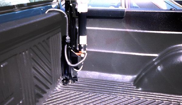
8 Chapter 3 Installation The first step is to unpack the box C arefully check all shipping boxes for contents since material is often packed in layers, put in plastic bags and taped to the inside of the box. Before you call to say something is missing, please check the entire package. Dump all the pieces out of the box. Almost every week someone calls to say something is missing, when in fact, the item is in the box. If you feel something is missing, please to us from the website at Use the contact us to send the . Please include complete information. Please do not call. Installing the manual control box The control box should be mounted in a convenient location since it will be used to tune the antenna. The control box is prewired. Simply put the cigarette lighter plug into an outlet. If you do not want the cigarette lighter plug or if it does not fit your outlet, just cut it off. The cable is supplied with a 2 amp fuse. The Black Hawk Motor draws about 300 ma. when running and about 1 amp at stall. We recommend that the fuse be no larger than 2 amperes. We have provided the plug for the wires to the motor. You can simply use butt connectors to make the connection to the wires that go to the antenna s motor. 5


9 The Black Hawk Motor will operate from 10 to 24 volts DC. For home or base use, power supplies are available from High Sierra. The light on the control box will illuminate when the antenna s coil is fully extended or fully retracted. The light may also blink when the antenna s motor is started. The lens on the light assembly may be red or green. It does not matter. Here are some things to keep in mind: You will need to supply 10 to 24 volts DC to the control box.. The supply needs to provide about 1 amp maximum. If the cigarette lighter plug is not needed or does not fit, cut it off. Do use a 2 amp fuse. Installing the i-box. The control box should be mounted in a convenient location since it will be used to tune the antenna. The control box is prewired. Simply plug the 4 pin connector into the back of your Icom transceiver s tuner jack. Power for the motor comes through that jack. We have provided the plug for the wires to the motor. You can simply use butt connectors to make the connection to the wires that go to the antenna s motor. Turn off your Icom transceiver. Plug the 4 pin connector into the AH-4 tuner jack on the back of your Icom transceiver. When the transceiver is powered-up, a signal from the i- Box tells the transceiver that an antenna is connected. 6

10 Operation of the i-box, Powered by Icom Think of the switch in the control box as having an extra set of contacts that close when the switch is rocked up or down. Each time you rock the switch the motor is turned on and the transceiver will transmit a carrier with reduced power. After the switch is released, the transceiver will continue to transmit for a few seconds giving you extra time to observe the built-in SWR meter. When rocking the switch, tune for an SWR of less than 2:1 and release the switch. The antenna is tuned. It is just that simple. For Icom transceivers with a built-in antenna tuner, there is a slightly different process. Press and hold the tuner button on the face of the transceiver for about 1 second. When you hear a tone from the speaker, then rock the switch to tune the antenna. As you rock the switch, the transmit indicator on the transceiver will light indicating that the transceiver is transmitting in the tune mode at 10 watts. For practice, do this process a few times. The light on the control box will illuminate when the antenna s coil is fully extended or fully retracted. The light may also blink when the antenna s motor is started. This is normal and expected. The lens on the light assembly may be red or green. It does not matter. expected. The lens on the light assembly may be red or green. It does not matter. The i-box will not function properly with the IC Please see the next section for information on the i-box 7000 that is specifically manufactured for the IC Installing the i-box The control box should be mounted in a convenient location since it will be used to tune the antenna. We have provided the plug for the wires to the motor. You can simply use butt connectors to make the connection to the wires that go to the antenna s motor. Turn off your Icom transceiver. Plug the 13 pin din connector into matching din jack on the rear of the IC When the transceiver is powered-up, the i-box 7000 will get the voltage for the motor from the IC-7000 and cause it to transmit when the switch it rocked. 7


11 Operation of the i-box 7000 Because of the firmware inside the IC-7000, it does not have a functioning SWR meter when the transceiver is in the tune mode. That is very different from other Icom transceivers. In order for the transceiver to indicate an SWR, it cannot be in the tune mode but must be transmitting in RTTY, FM or AM. So, in order to tune the antenna, push the Mode switch until the IC-7000 is in the AM mode. If you are in SSB, that will take 3 pushes of the switch. Putting the transceiver into AM will reduce power to about watts. Think of the switch in the control box as having an extra set of contacts that close when the switch is rocked up or down. Each time you rock the switch the motor is turned on and the transceiver will transmit an AM carrier and the SWR meter will indicate the SWR at the final transistors as it should. When you have obtained an SWR of less than 2:1, release the rocker switch and push the Mode button 1 more time to get back to SSB. The light on the control box will illuminate when the antenna s coil is fully extended or fully retracted. The light may also blink when the antenna s motor is started. This is normal and expected. The lens on the light assembly may be red or green. It does not matter. Installing the k-box. The k-box controller should be mounted in a convenient location since it will be used to tune the antenna. The controller is prewired. Simply plug the 6 pin connector into the back of your Kenwood transceiver s tuner jack while it turned off. Power for the motor comes through that jack. We have provided the plug for the wires to the motor. You can simply use butt connectors to make the connection to the wires that go to the antenna s motor. Turn off your Kenwood transceiver. Plug the 6 pin connector into the tuner jack on the back of your Kenwood transceiver. When the transceiver is powered-up, a signal from the k-box Controller tells the transceiver that an antenna tuner is connected. 8
12 Operation of the k-box. The k-box controller works a little differently from the i-box due to the internal circuitry of the Kenwood transceivers. The k-box handshakes with the transceiver so that it thinks there is an antenna tuner connected. To tune, you first press the AT buttom on the front of the transceiver. The transceiver will transmit a carrier with reduced power (about watts). When the rocker switch is moved, the motor is turned on and the coil will move either up or down. To take the transceiver out of the tune mode, you can press the AT switch again or wait for the transceiver to time out. Most Kenwood transceivers have a tuning time of just under one minute. When rocking the switch while in the tune mode, watch the transceiver s built-in SWR meter. Tune for an SWR of less than 2:1 and release the switch. The antenna is tuned. It is just that simple. The light on the control box will illuminate when the antenna s coil is fully extended or fully retracted. The light may also blink when the antenna s motor is started. The lens on the light assembly may be red or green. It does not matter. For the Kenwood TS-480HX, we have constructed a special control box. The reason for that is that the 200 watt version of the TS-480 will only transmit 100 watts when an antenna tuner is connected. As a result, our special control box for the Kenwood TS-480HX does not communicate with the transceiver. That is, the 480HX will not think that there is an antenna tuner connected and reduce power. Only the voltage for the motor will be taken from the transceiver. We recommend that you program the PF key to be the tune key for the transceiver. It is a simple process discussed in the 480 instruction manual to program the PF key. To tune the antenna with the PF programmed to be the tune key, you will press the PF key and then rock the up/down switch. Watch the transceiver s SWR meter and tune for an SWR of less than 2:1. When the SWR is less than 2:1, the antenna is tuned. The light on the control box will illuminate when the antenna s coil is fully extended or fully retracted. The light may also blink when the antenna s motor is started. The lens on the light assembly may be red or green. It does not matter. 9


13 Installing the Universal y-box, EZ-Tune Controller. The Universal y-box Controller should be mounted in a convenient location since it will be used to tune the antenna. The controller is prewired. Turn off the transceiver. There are three cables coming from the box. One has a cigarette lighter plug. That is connected to your power supply. If you don t need the cigarette lighter plug, then simply cut it off. The molded black plug with the red/black wires is connected to the matching plug on the antenna. We have provided pig tail connector to help with the wiring. The third cable coming out of the controller has a three conductor 1/8 inch plug. That is a standard stereo plug. That plugs into the ACC Jack on the back of your FT-857 or FT-897. In your instructions, it is likely labeled number 4 as shown in the picture below. Think of the switch in the control box as having an extra set of contacts that close when the switch is rocked up or down. Each time you rock the switch the motor is turned on and the transceiver will transmit a carrier. After the switch is released, the transceiver will continue to transmit for a few seconds giving you extra time to observe the built-in SWR meter. When rocking the switch, tune for an SWR of less than 2:1 and release the switch. The antenna is tuned. The light on the control box will illuminate when the antenna s coil is fully extended or fully retracted. The light may also blink when the antenna s motor is started. This is normal and expected. The lens on the light assembly may be red or green. It does not matter. 10

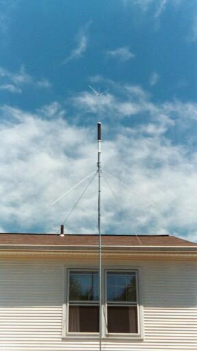
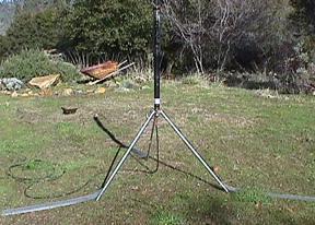
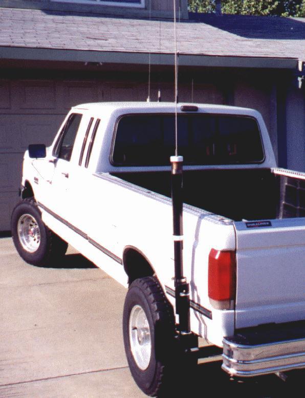
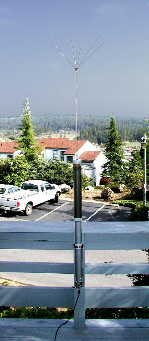
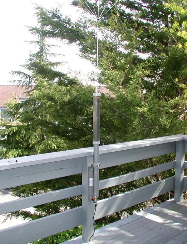
14 Universal Mounting Bracket and how to install it If you want to install an HS-1800/PRO on a pickup truck, sport utility vehicle, recreational vehicle, family car, balcony, roof, tower, TV mast, tripod, fence post or a stake in the backyard, you should use the HS-201C Universal Mounting Bracket. It can be adapted to many different installations. There are six holes in the mounting bracket. Two holes are on the center line about 12 inches apart. There are four other holes that can be used with the provided u- bolts and saddles so that the mounting bracket can be attached to a pipe with a maximum outside diameter of 1¼ inches or a standard TV mast. This very popular mount provides all the support needed for the HS-1800/PRO Continuous Coverage Motor Driven HF Antenna. The HS-201C also has our exclusive Easy-Off tapered brass stud and coax connector. The stainless steel hose clamp at the top of the Universal Mounting Bracket securely holds the antenna in place. When that is loosened, the antenna can be lifted from the mount. That hose clamp must be around the insulator on the antenna. Otherwise, the antenna is shorted out to the mounting bracket and it will not function. Although most hardware supplied with the antenna is stainless steel and should not corrode, the standard mounting bracket is constructed from steel. Some areas of the mounts are purposely left unpainted (powder coated) to allow a good electrical connection to be made. Edges of the mounting brackets need to be cleaned and waxed occasionally to keep from rusting. An optional stainless steel mounting bracket is available; HS-201C/SS. This stainless steel mounting bracket is included in some packages. Whether the antenna is to be used on a vehicle or at a home/base, the ground, radials or counterpoise are to be connected directly to the bottom of the mounting bracket using the stainless steel ¼ - 20 x 1 inch long screw adjacent to the coax connector. Make sure there is a good RF connection to that screw. 11
15 Here are some things to keep in mind: The hose clamp must be around the insulator on the antenna. Otherwise, the antenna will not tune. Vehicle ground connections, counterpoise or radials must be connected to the screw on the mounting bracket. A stainless steel version that is powder coated is also available. It will not rust. The all important ground, counterpoise or radial connection Since the HS-1800/PRO is electrically a quarter-wave antenna, a good vehicle grounding system, counterpoise or radials is absolutely essential for best performance. Any resistance introduced into the system impacts performance and can also cause high SWR readings. Long vehicle ground leads should be avoided. If the SWR is higher than 2:1, the problem is likely the ground, counterpoise or radial system that you have employed. It is not the result of something inside the antenna. You must use wide, flat strap for vehicle ground leads. Do not use braid. A counterpoise or radials must be connected directly to the screw on the mounting bracket that is next to the coax connector. Here are some things to keep in mind: For a ground strap to work, it must be at least one inch wide. You can use the specially designed HS-GS ground strap from High Sierra. Wire and round cables generally will not work. Don t use them! Don t use braid. It will corrode over time and affect the SWR of the system. Some braid has a high resistance path to ground. Half inch wide braid is roughly equal to #12 wire. In other words, it is almost useless. Connect the ground strap to the sheet metal of the vehicle. Connecting the ground strap to the frame may not be adequate. More than one ground strap may be necessary. That is especially true on 10 and 6 meters. The ground strap must be connected to the screw on the mounting bracket that is adjacent to the coax connector. 12

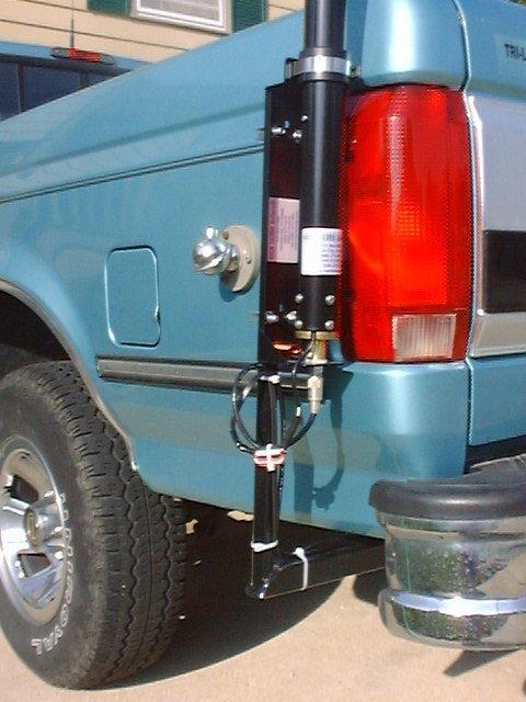
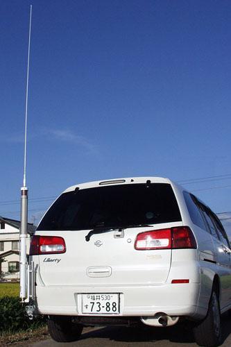
16 For home or base use, the counterpoise or radials must be connected to the screw on the mounting bracke that is adjacent to the coax connector. Please do not connect the ground strap, counterpoise or radials to some other place and call us to say the antenna does not work. RF Filter Assembly The RF filter assembly helps isolate the motor wires from the antenna. This RF filter or choke also helps with noise generated by the motor s brushes. The wires should loop through the bead 2 times. The ferrite bead is brittle and can be broken. So, be careful. We recommend that you mount the filter close to the mounting bracket. Here are some things to keep in mind: The RF filter needs to be close to the antenna. The color of the wires through the bead does not matter. If you drop the bead, it will crack. Vehicle Installation Our experience is that the antenna can function well in several locations on a vehicle. The length of the ground strap should be kept to less than three feet long (from the screw on the mounting bracket to the vehicle body/frame). Sometimes it's a good idea to test the location first. The ground strap should first be connected to the sheet metal of the vehicle. If the SWR on 20 meters or 15 meters is above 2:1, another strap to the frame may also be necessary. If the SWR is above 2:1 on 40 meters, stretching the matching coil should help. That will decrease the inductance and the impedance. The matching coil may be stretched up to twice its initial length. Use at least 20 feet of coax. Short runs of coax can affect the SWR reading at the transceiver. 13
17 If a vehicle has a 2 inch by 2 inch receiver hitch or the 1.25 inch by 1.25 inch receiver hitch the HS-201C can be combined with one of our adapters to provide another method to install your antenna. The HS202CL and the HS-214CL adapters can be folded down to allow for opening the rear door or tail gate. These adapters are perfect for a pickup truck, van, passenger car or SUV. Long supports below the antenna can cause matching problems. If you must use a long support, try grounding it first. If the antenna will not tune on one or two bands, try isolating the support from ground. Ladders on recreational vehicles are also problematic. While many have had very successful installation on ladders, others have had difficulty. Some have found that running a ground strap from the mounting bracket to the metal framing of the RV is all that is needed. Others have had to run one or two radials on the top of the RV. Some have found that metal trim and luggage racks are all that is needed. Mounting the base of the antenna low and close to the frame is another way to the get the antenna to tune properly. In other words, some experimenting is necessary for installation on an RV. If you pull a trailer and plan to mount the antenna on the towing vehicle, make sure there is a good RF connection between the towing vehicle and the trailer. If this is not done, you may soon discover your antenna has an intermittent connection. The problem is caused by loose (intermittent) coupling between the vehicles through the trailer hitch. A simple jumper cable across the hitch corrects the problem. In addition to planning where you will mount the antenna, also consider how the cables will be routed. Be especially careful to keep cables and wires away from exhaust pipes, catalytic converters, other bundles of wires and computers. Note: Your number one concern with installing any antenna is safety. Use extreme care installing and using this antenna. Another location consideration is the overall height of the antenna system. You risk hitting bridges and over-passes when the antenna height exceeds 13 feet/4m. There are safety considerations as well. You are responsible for antenna safety. Here are some things to keep in mind: You are responsible for safety, safety, safety and more safety. The ground strap should be less than three feet. You may need to spread the matching coil in order to lower the SWR on 40 meters. 14

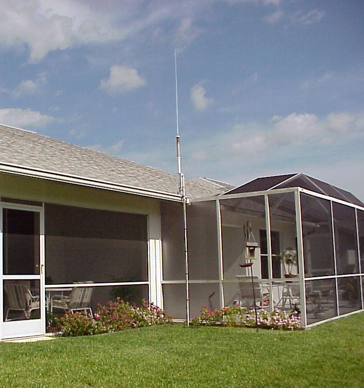
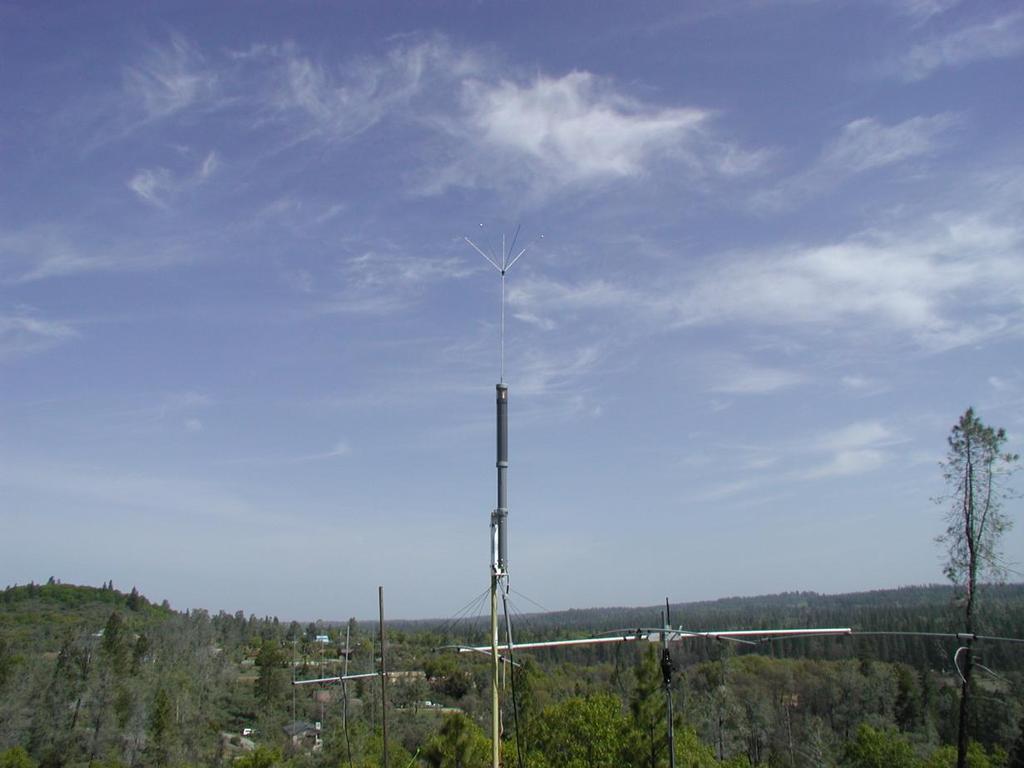
18 High Sierra Antennas has adapters for 1¼ inch and 2 inch receiver hitches: HS-202C, HS-202CL, HS-214C & HS-214CL. Keep the total antenna height less than 13 feet above the ground. Use at least 20 feet of coax between the antenna and the transceiver. Some experimenting may be needed. Base Installation For a base installation, the radials or counterpoise must be connected to the screw adjacent to the coax connector on the bottom of the mounting bracket. The radials can be as simple as wire that is cut to a quarter wavelength. We have found that wires 32, 16, 11 and 8 feet long will provide continuous coverage from 3.5 to 30MHz. You can also use 8 wires that are 10 feet long. The radials should be spread out like spokes on a wheel. The matching coil is not needed. With radials attached to the screw on the mounting bracket, the antenna will tune to resonance with an impedance close to 50 ohms. Generally speaking, burying of radials increases ground losses. So, having the radials on the top of the ground will increase performance. Like most HF antennas, generally speaking higher is better. However, most of us must compromise. So, if you can put it up on the roof, it is better. If you cannot use the roof, then install the antenna on the ground. Here are some things to keep in mind: You are responsible for safety, safety, safety. No matching coil is needed on the mounting bracket. Higher is better but for some, the antenna must be low. Radials or a counterpoise will be needed. A driven ground stake or grounding rod is useless. The radials or counterpoise must be connected to the screw next to the coax connector. 15
19 No matter where you install the antenna, here are some things to keep in mind Think about safety, safety, and more about safety! Your first concern is making sure that neither you nor anyone else will be injured. Adding a db to the signal strength won t matter if someone is injured. Don t use braid. Typically, braid is not much better than a small diameter wire. Either use our HS-GS ground strap or a flat wide strap of sheet metal. Plumber s tape or pipe strap sold in hardware stores is a very good ground strap. Please don t call to say the antenna won t tune if you have used braid. The connection of the ground strap must be made to the screw designed for that task. Try not to re-engineer the antenna design. With almost 10,000 antennas in use around the world, we have worked very hard to make this antenna the best possible. A long whip will add signal strength on 40 and 80 meters. However, the antenna will become too long for resonance on 10 and perhaps lower frequencies. Make certain that the strap that holds the antenna to the mounting bracket is around the insulator on the antenna and not around the metal of the antenna. We strongly recommend that there be at least 20 feet of coax between the antenna and the transceiver. For a vehicle installation, stretching of the matching coil may be needed in order bring the SWR down on 40 meters. The coil may be stretched over 1 inch without damage. For base installations, no matching coil is needed. 16
20 17
21 18
22 19
23 20
24 21
25 22
26 23

27 24
28 25
29 26
30 27
31 28
.")
32 Chapter 4 Operation of the Antenna The ups and downs of the antenna The following assumes that there is a six foot whip attached to the top of the antenna: Adjust the control switch so that about 4 inch of the coil winding is above the collar. Set the transceiver to a mode that produces a steady-state carrier (AM, RTTY, CW or FM). Generally speaking, you cannot tune the antenna for minimum SWR while in the SSB mode. Set the transceiver to 7200KHz and reduce power to 10 to 20 watts. Watch the SWR meter and continue to increase the inductance by moving the coil up until a sharp dip in the SWR occurs. Adjust for lowest reading by moving the control switch back and forth. You are now tuned to 7200 KHz. Increase the power to approximately 100 watts and recheck for resonance. Due to the design of the SWR meter, a minor adjustment to the antenna will likely be needed when the power is increased. SWR meter do change readings when the power level is changed. If your transceiver does not have an SWR meter, you can use the power output meter. Just tune for maximum output which will occur at minimum SWR. It does not matter whether or not you use maximum out watts or minimum SWR. Either reading will result in a properly tuned antenna at a frequency. You can also get the antenna close to the proper frequency by simply listening for noise in the receiver. As the antenna goes to the receive frequency, the noise in the receiver will come up and then go down as the antenna s frequency goes past the receiver s frequency. The highest frequency occurs at the minimum inductance position. That is, with the coil fully retracted it will be on 10 meters. Tuning will be sharpest on the 80 meter band and broadest on 10 meters. In some installations, the lowest frequency may occur above 3.5 MHz. 29
33 Here are some approximate positions of the main coil. The measurement shown is from the first turn on the main coil to the top of the collar. Time measurements were done in a vehicle. 75 Meters 11½ inches 108 seconds 40 Meters 4 inches 26 seconds 20 Meters 1 inch 8 seconds 15 Meters ½ inch 4 seconds 10 Meters 0 0 seconds (fully retracted) Due to the variables in any given installation, the position of the coil can be different from the dimensions shown above. The above assumes that there is a six foot long whip or its equivalent connected to the top of the antenna. In other words, if you attach a fiberglass CB whip to the antenna, it will not tune the same way. 30
34 Chapter 5 Troubleshooting, Questions and Answers Here are some of the typical questions that we get Q: How long is the six foot whip? A: The whip is 72 inches long. Q: My antenna on the car has a high SWR on 10 meters. The SWR is 3:1. What s wrong? A: You need to improve the ground connection or add a second ground strap. Q: My SWR is really high. It s 1.9:1. What can I do about that? A: Don t worry about it. An SWR of 1.9:1 is terrific. Did you know that an SWR of 5:1 results in only a 1/6 of an S unit decrease in signal strength? If the SWR is less than 2:1, most transceivers will not roll back power. Q: The SWR on 20 meters is higher than all of the other bands. Why? I ran braid to the frame of the car. A: Well likely there is an inadequate ground connection. First of all, don t use braid. Second, use a flat wide strap. I would add a second ground strap to the sheet metal of the vehicle. You should also try another length of coax. Q: On my transceiver, the high SWR icon comes on all of the time. What s that about? A: It is a known problem with that transceiver. Please contact the manufacturer for a fix. Q: I hooked up the antenna and the SWR is very high. I think the antenna is shorted out. Is that possible? 31
35 A: No, it is not possible for the antenna to short out. First check to see if you have the strap that holds the antenna to the mounting bracket around the antenna or around the insulator on the antenna. Second, replace the coax with some known to be good that already has the connectors installed. The coax should be at least 20 feet long. Q: I think something is loose inside my new antenna. When I turn it upside down, I hear a rattle. Should I send the antenna back? A: No. What you are hearing are the stainless steel washers on the lead screw sliding down its length. That is a normal sound to hear. Q: I took an ohmmeter and connected it to the coax. There is a short circuit. I think the antenna is shorted out. A: The antenna cannot short out. There is a shunt coil from the center conductor to ground on the HS-201C and HS-201C/SS when the antenna is used on a vehicle. With an ohmmeter, it will read as a short. On the other hand, with RF it will match the impedance of the antenna to the 50 ohm cable. Q: The coil spins when I try to move it up or down. What s wrong? A: The coil cannot spin if the weathershield is tight. The key on the outside of the aluminum tube and keyway in the weathershield keep the coil from spinning. You need to tighten the whip or quick disconnect. Q: The main coil won t go up and down. What s wrong? A: You first need to check the spring that makes contact with the coil. To do that, remove the whip and quick disconnect. Remove the two screws in the top or bottom cap of the weathershield. Lower or remove the weathershield. Loosen the three set screws in the collar that holds the spring. Remove the collar. Remove the contact spring from the collar. If the spring is not uniform, it must be replaced. Q: The spring wore out or is deformed. Why did that happen? A: Well, the contact spring is subjected to a lot of vibration. It is made from stainless steel and is a patented device. Over time, it will wear out. We recommend that the spring be replaced about once a year. We tried fingerstock and found that it wore out very quickly and required that the antenna be returned for repair. Fingerstock contains Berrylium which is an extremely hazardous material. We don t want our employees or you to be exposed to Berrylium. The spring is stainless steel, relatively inexpensive and very simple to replace. In addition, it is impossible for the spring to lose contact with the coil. Fingerstock cannot maintain contact over time. 32
36 Q: My SWR is 1:6. What s wrong? A: Well first, the SWR is expressed as X:1. So, if you mean the SWR is 6:1, I would check the coax connectors for a short or an open. The best way to do that is to replace the coax with new 33
37 Chapter 6 10 Year Limited Warranty High Sierra Antennas have a 10 year limited warranty High Sierra Antennas and Heath Tech Inc. warrants to the original purchaser of the antenna and accessories are free from defects in material and workmanship for a period of one year from the date of original purchase when used in compliance with the instructions and maintained as shown in this instruction manual. The Black Hawk Motor has a ten year limited warranty. The main coil also has a ten year limited warranty. In no event shall High Sierra Antennas or Heath Tech Inc. be responsible for incidental or consequential damages, nor damage due to misuse or the use of any unauthorized attachment(s). Damage to the product resulting from accident, abuse, neglect, negligence, alterations, unapproved attachments, alterations or other causes unrelated to problems with material or workmanship are not covered by this warranty. In the case of manufacturer defects in material or workmanship, High Sierra Antennas agrees to repair or remedy a defect without charge. The purchaser must obtain a return authorization number from High Sierra Antennas either by ing from the website; and use the contact us box.. Unauthorized returns will not be accepted. The returned product must be clean. The product must be properly boxed and protected. Damage as the result of shipping is not covered by this warranty. 34
38 Index 1.25 inch by 1.25 inch receiver hitch, inch by 2 inch receiver hitch, 7 anti-oxidant, 2 base installation, 8 braid, 9 coax, 28 collar, 28 contact spring, 3 control box, 4 corrosion, 3 fingerstock, 28 fuse, 5 ground connection, 27 ground strap, 9, 27 HS-201C, 6 HS202CL, 7 HS-214CL, 7 HS-GS ground strap, 9 HS-Tripod, 8 A B C F G H lubricant, 29 main coil, 29 matching coil, 29 motor makes noise, 29 mounting bracket, 29 quick disconnect, 3 radials, 8 Routine maintenance, 2 RV, 7 M Q R S safety, 9 shunt coil, 28 spring, 29 switch, 5 SWR, 27 SWR is very high, 27 SWR of 2:1 or less is good, 1 trailer, 8 vehicle, 7 warranty, 30 weathershield, 2 whip, 3 T V W L Ladders on recreational vehicles, 7 length of coax, 27 35
39 36
Professional Antennas for the Amateur
 HEATH TECH INC. High Sierra AntennAs Sidekick Professional Antennas for the Amateur HIGH SIERRA ANTENNAS Heath Tech Inc.,/High Sierra AntennAs is located in the foothills of the Sierra Nevada Mountains
Tarheel Antennas, Inc.
 Tarheel Antennas, Inc. Instruction Manual for the Model 300A Continuous Coverage HF Antenna PROUDLY MADE IN THE UNITED STATES OF AMERICA 18511 CR 304 St. Joseph, MO 64505 816-671-9409 / 816-364-2619 Fax
Tarheel Antennas, Inc.
 Tarheel Antennas, Inc. Instruction Manual for the Model 100A-HP Continuous Coverage HF Antenna PROUDLY MADE IN THE UNITED STATES OF AMERICA 18511 CR 304 St. Joseph, MO 64505 816-671-9409 / 816-364-2619
Tarheel Antennas, Inc.
 Tarheel Antennas, Inc. Instruction Manual for the Model 40A-HP Continuous Coverage HF Antenna PROUDLY MADE IN THE UNITED STATES OF AMERICA 18511 CR 304 St. Joseph, MO 64505 816-671-9409 / 816-364-2619
REP Design LLC. 193 Winding Ridge Rd, Southington, CT INSTALLATION INSTRUCTIONS:
 REP Design LLC 193 Winding Ridge Rd, Southington, CT 06489 1-860.426.1894 n7emw@cox.net www.repdesign.us INSTALLATION INSTRUCTIONS: SHD-SO239 Super Heavy Duty SO-239Antenna Mounting System Thank you for
Installation Instructions Hustler 6-BTV Trap Vertical
 Installation Instructions Hustler 6-BTV Trap Vertical ASSEMBLY 1. Check the package contents against the parts list on page 2. 2. WARNING. Installation of this product near power lines is dangerous. For
Installation Instructions Hustler 6-BTV Trap Vertical
 Installation Instructions Hustler 6-BTV Trap Vertical ASSEMBLY 1. Check the package contents against the parts list on page 2. 2. WARNING. Installation of this product near power lines is dangerous. For
Tarheel Antennas, Inc.
 Tarheel Antennas, Inc. Instruction Manual for the Model 75A "Stubby" Continuous Coverage HF Antenna PROUDLY MADE IN THE UNITED STATES OF AMERICA 18511 CR 304 St. Joseph, MO 64505 816-671-9409 / 816-364-2619
MFJ-2982 Feather-Lite 80-6 Meter Vertical Antenna
 MFJ-2982 Feather-Lite 80-6 Meter Vertical Introduction: The MFJ-2982 is a lightweight 31-foot fiberglass antenna designed to mount on any convenient post, mast, or a suitable wide-stance tripod such as
Introduction LOADING COIL COUNTERPOISE ATTACHMENT ANTENNA ATTACHMENT. Figure 1: MFJ-1625 Window/Balcony Mount Antenna
 Introduction MFJ-1625 The MFJ-1625 is a 200 Watt antenna tuner that was designed to provide portable or permanent HF communications on 80 through 10 meters and VHF on 6 meters. The universal mount design
ALWAYS ATTACH THE SAFETY ROPE TO A STABLE SUPPORT BEFORE ATTEMPTING TO ATTACH THE UNIVERSAL MOUNT TO A WINDOW FRAME OR RAIL.
 MFJ-1623 Introduction The MFJ-1623 was designed to provide portable or permanent HF communications on 30 through 10 meters and VHF on 6 meters. The universal mount design allows the user to install the
MFJ-2389 Compact 8 Band Vertical
 MFJ-2389 Compact 8 Band Vertical The MFJ-2389 is an 8 band compact vertical that is designed to operate on 80, 40, 20, 15, 10, 6, 2M, and 70CM bands. The antenna will handle 200W PEP or 50W CW HF or 150W
INSTRUCTION MANUAL V-42R. Dual Band Collinear Gain Vertical for MHz and GENERAL DESCRIPTION
 308 Industrial Park Road, Starkville, MS 39759 USA Ph: (662) 323-9538 FAX: (662) 323-6551 V-42R Dual Band Collinear Gain Vertical for 144-148 MHz and 436-450 INSTRUCTION MANUAL GENERAL DESCRIPTION The
MFJ-969 Versa Tuner II Instruction Manual
 MFJ-969 Versa Tuner II Instruction Manual General Information The MFJ-969 is a 300 watt RF output power antenna tuner that will match any transmitter or transceiver to virtually any antenna. Peak or average
MFJ-949E. tuner antenowy skrzynka antenowa. Instrukcja obsługi. importer:
 Instrukcja obsługi MFJ-949E tuner antenowy skrzynka antenowa importer: PRO-FIT Centrum Radiokomunikacji InRadio ul. Puszkina 80 92-516 Łódź tel: 42 649 28 28 e-mail: biuro@inradio.pl www.inradio.pl MFJ-949E
PAC-12 Kit Contents. Tools Needed Soldering iron Phillips screwdriver Wire stripper Wrenches, 7/16 and 1/2 Terminal crimp tool Pliers Solder
 PAC-2 Kit Contents Part Quantity Screws: 8/32 x 3/8 Screws: 8-32 x 5/6 Screw: 8-32 x /4 #8 internal tooth washers #8 solder lug ring terminals Bolt: Aluminum, /4-20 x.5 /4 internal tooth washer Nut: Aluminum
Tarheel Antennas, Inc.
 Tarheel Antennas, Inc. Instruction Manual for the Little Tarheel HP Continuous Coverage HF Antenna PROUDLY MADE IN THE UNITED STATES OF AMERICA 18511 CR 304 St. Joseph, MO 64505 816-671-9409 / 816-364-2619
INSTRUCTION MANUAL. Model 18AVQII Five Band Vertical Antenna 10, 15, 20, 40, 80 Meter. General Description. Theory of Operation
 Model 18AVQII Five Band Vertical Antenna 10, 15, 20, 40, 80 Meter 308 Industrial Park Road Starkville, MS 39759 (662) 323-9538 Fax: (662) 323-5803 INSTRUCTION MANUAL General Description The Hy-Gain 18AVQII
Thank you for purchasing the Ameritron SDA-100 Antenna
 Thank you for purchasing the Ameritron SDA-100 Antenna When properly installed this antenna will provide continuous coverage of 3.5 to 30 MHz with a 6' whip, also 6.0 to 60 MHz without a whip. Installation
MFJ ENTERPRISES, INC.
 Model MFJ-2910 INSTRUCTION MANUAL CAUTION: Read All Instructions Before Operating Equipment MFJ ENTERPRISES, INC. 300 Industrial Park Road Starkville, MS 39759 USA Tel: 662-323-5869 Fax: 662-323-6551 VERSION
K1FO 12 ELEMENT 144/147 MHz YAGI
 K1FO 12 ELEMENT 144/147 MHz YAGI WARNING: INSTALLATION OF THIS PRODUCT NEAR POWER LINES IS DANGEROUS. FOR YOUR SAFETY FOLLOW THE INSTALLATION DIRECTIONS. Ariane Arrays, Inc. Copyright 2006 201 Hopedale
Antenna Disconnect THE INEXPENSIVE WAY TO PROTECT YOUR VALUABLE RADIO FROM LIGHTNING SURGES
 Antenna Disconnect THE INEXPENSIVE WAY TO PROTECT YOUR VALUABLE RADIO FROM LIGHTNING SURGES -------------------------------------------------------------------------------------- Operating Manual May 2017
TW4040. The Adventurer Monobander INSTRUCTION MANUAL. TransWorld Antennas
 TW4040 The Adventurer Monobander TransWorld Antennas INSTRUCTION MANUAL Contents 1 Limited Warranty 3 2 Important Safety Information 4 3 Specifications 3.1 Mechanical 4 3.2 Electrical 4 3.3 VSWR Performance
ASSEMBLY AND INSTALLATION INSTRUCTIONS R , 12, 15, 17, 20, 30, 40 Meters (5/99) COMMUNICATIONS ANTENNAS
 COMMUNICATIONS ANTENNAS") ASSEMBLY AND INSTALLATION INSTRUCTIONS R7000 10, 12, 15, 17, 20, 30, 40 Meters COMMUNICATIONS ANTENNAS 951465 (5/99) WARNING THIS ANTENNA IS AN ELECTRICAL CONDUCTOR. CONTACT WITH POWER LINES CAN RESULT
ASSEMBLY AND INSTALLATION INSTRUCTIONS R7000 10, 12, 15, 17, 20, 30, 40 Meters COMMUNICATIONS ANTENNAS 951465 (5/99) WARNING THIS ANTENNA IS AN ELECTRICAL CONDUCTOR. CONTACT WITH POWER LINES CAN RESULT
CP6A. 6 Band Trap Vertical 75-6m
 CP6A 6 Band Trap Vertical 75-6m Instruction Sheet The CP6A is a multi-band trap-vertical antenna for HF bands, covering the 75*, 40, 20, 15, 10m & 6m amateur bands. Made from heavy duty aluminum, the CP6A
User Guide for the Alpha Loop Sr Antenna
 User Guide for the Alpha Loop Sr Antenna Manufactured by: Alpha Antenna 1.888.482.3249 Website: http://alphaantenna.com Available from: Amateur Radio Store Website: https://amateurradiostore.com User Guide
Ameritron RCS-10 INTRODUCTION
 Ameritron RCS-10 INTRODUCTION The RCS-10 is a versatile antenna switch designed for 50-ohm systems. It handles high power, and sealed relays offer excellent life and connection reliability. It requires
HFp. User s Guide. Vertical. entenna. 7 MHz 30 MHz Amateur Radio Antenna Plus 6-Meters
 User s Guide HFp Vertical 7 MHz 30 MHz Amateur Radio Antenna Plus 6-Meters The Ventenna Co. LLC P.O. Box 2998, Citrus Heights, CA, 956 www.ventenna.com entenna Table of Contents The HFp Antenna -------------------------------------------------------------------
Directive Systems & Engineering 2702 Rodgers Terrace Haymarket, VA
 Directive Systems & Engineering 2702 Rodgers Terrace Haymarket, VA 20169 1628 www.directivesystems.com 703 754 3876 K1JX DESIGNED 6 ELEMENT 50 MHZ YAGI, DSEJX6 50 INTRODUCTION The Directive Systems DSEJX6-50
The W3FF Portable Dipole
 The W3FF Portable Dipole This is the antenna I designed for my 'walking portable' station. It is a dipole constructed out of the plastic plumbing pipe CPVC. There are telescoping whips at the ends of each
Guide. Installation. Wilson Electronics, Inc. Direct Connection High Power iden Amplifi er 800 MHz Band. Contents:
 Amplifier Installation Guide Direct Connection High Power iden Amplifi er 800 MHz Band Contents: Guarantee and Warranty 1 Before Getting Started / How it Works 3 Installing a Wilson Outside Antenna - In-Vehicle
Introduction. Understanding Power Ratings. Peak Reading SWR/Wattmeter
 Introduction The MFJ-962D is a "T" network roller inductor tuner with built-in antenna switching, RF power and SWR metering and a 1:1 balun. The largest amplifiers that can safely be used include the Heathkit
Directive Systems & Engineering 2702 Rodgers Terrace Haymarket, VA
 Directive Systems & Engineering 2702 Rodgers Terrace Haymarket, VA 20169-1628 www.directivesystems.com 703-754-3876 25 Element 7.4 wl. K1FO Designed Yagi, Model DSEFO432-25 ELECTRICAL SPECIFICATIONS Frequency
INSTRUCTION MANUAL ORDER NO. V3R MODEL V3R. Collinear Gain Vertical for MHz
 ORDER NO. V3R MODEL V3R Collinear Gain Vertical for 216-225 MHz INSTRUCTION MANUAL General Description The new Hy-Gain V3R VHF antenna is a collinear 5/8-wave omnidirectional vertical antenna for the 216-225
TZ-RD-1740 Rotary Dipole Instruction Manual
 TZ-RD-1740 17/40m Rotary Dipole Instruction Manual The TZ-RD-1740 is a loaded dipole antenna for the 40m band and a full size rotary dipole for the 17m band. The antenna uses an aluminium radiating section
INSTRUCTION MANUAL. Specifications Electrical. Front-To-Back Ratio VSWR at Resonance Less than 1.5:1 Nominal Impedance. Mechanical
 300 Industrial Park Road, Starkville, MS 39759 Ph: (662) 323-8538 FAX: (662) 323-6551 TH-3JRS Tri-band HF 3 Elements Beam Covers 10, 15 and 20 Meters INSTRUCTION MANUAL WARNING Installation of this product
M2 Antenna Systems, Inc. Model No: 20M5LD
 M2 Antenna Systems, Inc. Model No: 20M5LD SPECIFICATIONS: Model... 20M5LD Frequency Range... 14.0 14.350 MHz *Gain (Full Band)... 10.2 dbi Typical Front to back... 23 db Typical Beamwidth... E=50 / H=66
00108/00110 INSTRUCTION MANUAL
 00108/00110 INSTRUCTION MANUAL Removable and Adjustable Mudflap System IMPORTANT! Please Read this Instruction Booklet prior to assembly of your Rock Tamer Kit. IMPORTANT! Exhaust Systems Note: Any modifications
INSTRUCTION MANUAL. Model 18AVQII Five Band Vertical Antenna 10, 15, 20, 40, 80 Meter
 Model 18AVQII Five Band Vertical Antenna 10, 15, 20, 40, 80 Meter 308 Industrial Park Road Starkville, MS 39759 (662) 323-9538 Fax: (662) 323-5803 INSTRUCTION MANUAL General Description The Hy-Gain 18AVQII
U.S. Rack, Inc Falcon Drive, Madera, CA APR17 INSTALLATION AND USE INSTRUCTIONS for SIDE-MOUNT LADDER RACK
 U.S. Rack, Inc. 2850 Falcon Drive, Madera, CA 93637 15APR17 INSTALLATION AND USE INSTRUCTIONS for SIDE-MOUNT LADDER RACK WARNING: Do NOT attempt to install or use this rack without following all instructions.
Technician Licensing Class. Lesson 4. presented by the Arlington Radio Public Service Club Arlington County, Virginia
 Technician Licensing Class Lesson 4 presented by the Arlington Radio Public Service Club Arlington County, Virginia 1 Quiz Sub elements T6 & T7 2 Good Engineering Practice Sub element T8 3 A Basic Station
MFJ Balanced Line Tuner
 MFJ Balanced Line Tuner Introduction The MFJ-974H balanced line antenna tuner is a fully balanced true balanced line antenna tuner, providing superb current balance throughout a very wide matching range
WA4DXP. Mobile Antennas. Mounts, Antennas, Tuners (or not) & grounding Presented by M.D. Smith
 & grounding Presented by M.D. Smith") WA4DXP Mobile Antennas Mounts, Antennas, Tuners (or not) & grounding Presented by M.D. Smith Mounts Mobile Antennas WA4DXP Bolt on antenna mount... Same as used on heavy truck mirror mount Sheet metal
WA4DXP Mobile Antennas Mounts, Antennas, Tuners (or not) & grounding Presented by M.D. Smith Mounts Mobile Antennas WA4DXP Bolt on antenna mount... Same as used on heavy truck mirror mount Sheet metal
Cushcraft. Amateur Radio Antennas LFA-6M5EL. 6 Meter 5 Element Loop Feed Antenna INSTRUCTION MANUAL
 Cushcraft Amateur Radio Antennas LFA-6M5EL 6 Meter 5 Element Loop Feed Antenna INSTRUCTION MANUAL CAUTION: Read All Instructions Before Operating Equipment VERSION 1A Cushcraft Amateur Radio Antennas 308
Installation Instructions:
 NOTE: Carefully read entire instructions thoroughly before attempting to install this part. (SB76904) Parts Included Qty 94-241CA001 Front Upright: Drvr 1 94-241CA002 Front Upright: Pass 1 94-241CA003
Installation & User Guide. For Powering Distributed Audio Systems A45-X2 TWO CHANNEL AMPLIFIER
 Installation & User Guide For Powering Distributed Audio Systems TWO CHANNEL AMPLIFIER A45-X2 A45-X2 TWO CHANNEL AMPLIFIER TABLE OF CONTENTS Features...1 Product Overview...2 Package Contents...4 Preparing
CON NEX HP. OWNER'S MANUAL Full Channel AM/FM Amateur Mobile Transceiver TABLE OF CONTENTS TUNING THE ANTENNA FOR OPTIMUM S.W.R..
 TABLE OF CONTENTS PAGE SPECIFICATIONS... 2 INSTALLATION... 3 LOCATION... 3 CON NEX - 4300HP MOUNTING THE RADIO... 3 IGNITION NOISE INTERFERENCE... 4 ANTENNA... 4 TUNING THE ANTENNA FOR OPTIMUM S.W.R..
mat-180h HF-SSB Automatic Antenna Tuner Instruction Manual Version V1.0
 INTRODUCTION mat-180h HF-SSB Automatic Antenna Tuner Instruction Manual Version V1.0 The mat-180h is an automatic tuner intended for use with modern Icom transceivers. It works with any Icom transceiver
Tarheel Antennas, Inc.
 Tarheel Antennas, Inc. Instruction Manual for the Little Tarheel II Continuous Coverage HF Antenna PROUDLY MADE IN THE UNITED STATES OF AMERICA 18511 CR 304 St. Joseph, MO 64505 816-671-9409 / 816-364-2619
LDG TW-1 Talking Wattmeter
 LDG TW-1 Talking Wattmeter LDG Electronics 1445 Parran Road, PO Box 48 St. Leonard MD 20685-2903 USA Phone: 410-586-2177 Fax: 410-586-8475 ldg@ldgelectronics.com www.ldgelectronics.com 1 LDG TW-1 Talking
TW2010. The Adventurer INSTRUCTION MANUAL. Trans World Antennas
 TW2010 The Adventurer Trans World Antennas INSTRUCTION MANUAL Danger: Do not install this antenna where there exists the possibility of contact with power lines. Even with painted or coated antennas, the
How to use your antenna tuner.
 How to use your antenna tuner. There's more to it than what is in your manual or on most how to do it websites! http://www.arrl.org/tis/info/ant-tuner-op.html Here is a neat site with a "T" network simulator.
THE W3FF HOMEBREW BUDDIPOLE
 THE W3FF HOMEBREW BUDDIPOLE A PORTABLE ANTENNA DESIGN FOR AMATEUR RADIO History of the Buddipole In January of 2000, I began experimenting with a walking portable ham station. Since then, thousands of
Appearance of device and accessories may vary.
 Mobile 4G Smart Technology Signal Booster Contents: How it Works.... 1 Before Getting Started.... 2 Quick Installation Overview.... 2 Installing the Outside Antenna.... 2 Installing the Low-Profile Antenna....
INSTALLATION INSTRUCTIONS: SHD-SO239-LA(2.0
 REP Design LLC Southington, CT 06489 860.426.1894 n7emw@cox.net INSTALLATION INSTRUCTIONS: SHD-SO239-LA(2.0 & 2.5) Antenna L Bracket Base with SS SO239 Connector Thank you for your purchase; we appreciate
The MFJ-1754 can be mounted on any 1" to 1 1/2" mast (conductive or non conductive.)
") INTRODUCTION: The MFJ-1754 is designed for use on the 2 meter and the 70 centimeter bands. On the 2 meter band the MFJ-1754 behaves as a vertical 1/4 wave antenna, however on 70 centimeter band the MFJ-1754
INTRODUCTION: The MFJ-1754 is designed for use on the 2 meter and the 70 centimeter bands. On the 2 meter band the MFJ-1754 behaves as a vertical 1/4 wave antenna, however on 70 centimeter band the MFJ-1754
Portable Dipole Shortwave Antenna (PDSA-7)
") PACKING LIST 1 Connection base 1 (Material: Nylon) 2 Multiband loading coil 2 (40m-10m, material: Nylon) 3 Aluminum oxide tube 4 (19 X 280mm) 4 Extractable antenna (on the top) 2 (Each fully extracted
PACKING LIST 1 Connection base 1 (Material: Nylon) 2 Multiband loading coil 2 (40m-10m, material: Nylon) 3 Aluminum oxide tube 4 (19 X 280mm) 4 Extractable antenna (on the top) 2 (Each fully extracted
DX 29HP. 10 Meter Amateur Mobile Transceiver OWNER S MANUAL PRINTED IN MALAYSIA PN:A412308CNA
 DX 29HP 10 Meter Amateur Mobile Transceiver OWNER S MANUAL PRINTED IN MALAYSIA PN:A412308CNA TABLE OF CONTENTS Page Specification.................................... 2 Installation Location.....................................
SawStop. Contractor Fence Assembly OWNER S MANUAL. Model CNS-SFA
 Contractor Fence Assembly OWNER S MANUAL Model CNS-SFA Warranty warrants to the original retail purchaser of the Contractor Fence Assembly accompanying this manual that the fence assembly will be free
Scorpion. Home Installation Manual
 Scorpion Home Installation Manual Thank you for selecting Scorpion as your antenna! Ron Douglass, NI7J http://www.scorpionantennas.com scorpionantennas@cox.net 623-326-8780 All Scorpion antennas, SA- 680,
Balishutters. INSTALLATION guide FOR L-FRAME MOUNT INSTALL OPTIONS B OR C
 Balishutters INSTALLATION guide FOR L-FRAME MOUNT INSTALL OPTIONS B OR C Tools needed for installation Drill Phillips bit 1/8" drill bit 4. Hammer (preferably hard plastic) 5. Level 6. Phillips-head screwdriver
LJ element beam for 10 or 12 meters INSTRUCTION MANUAL. CAUTION: Read All Instructions Before Operating Equipment
 LJ-113 3 element beam for 10 or 1 meters INSTRUCTION MANUAL CAUTION: Read All Instructions Before Operating Equipment 308 Industrial Park Road Starkville, MS 39759 USA Tel: 66-33-9538 Fax: 66-33-6551 VERSION
CP6 6 Band Trap Vertical 80-6m
 CP6 6 Band Trap Vertical 80-6m Instruction Sheet The CP6 is a multi-band trap-vertical antenna for HF bands, covering the 80*, 40, 20, 15, 10m & 6m amateur bands. Made from heavy duty aluminum, the CP6
Owner's Manual AM/FM STEREO RADIO WITH AUTO STOP CASSETTE PLAYER. Designed Specifically for the Marine and RV Environment
 Owner's Manual AM/FM STEREO RADIO WITH AUTO STOP CASSETTE PLAYER Designed Specifically for the Marine and RV Environment FACEPLATE CONTROLS DIAGRAM (Figure 1) 1 2 3 4 10 9 8 1 POWER BUTTON Press it to
Yagi and Omni Antennas Installation Manual
 Yagi and Omni Antennas Installation Manual 25500445 Rev. A0 0218 Printed in U.S.A. Copyright 2018 Federal Signal Corporation Limited Warranty This product is subject to and covered by a limited warranty,
1997 MFJ ENTERPRISES, INC.
 INSTRUCTION MANUAL CAUTION: Read All Instructions Before Operating Equipment MFJ ENTERPRISES, INC. 300 Industrial Park Road Starkville, MS 39759 USA Tel: 601-323-5869 Fax: 601-323-6551 VERSION 6C COPYRIGHT
INSTRUCTION MANUAL. Specifications Mechanical. 1 5/8 to 2 1/16 O.D. (41mm to 52mm)
") 308 Industrial Park Road Starkville, MS 39759 USA Ph: (662) 323-9538 FAX: (662) 323- General Description Model VB-25FM 2-Meter 5 Elements Beam INSTRUCTION MANUAL This antenna is a 5-element, 2-meter beam
308 Industrial Park Road Starkville, MS 39759 USA Ph: (662) 323-9538 FAX: (662) 323- General Description Model VB-25FM 2-Meter 5 Elements Beam INSTRUCTION MANUAL This antenna is a 5-element, 2-meter beam
Mirage B-320-G FEATURES
 Mirage B-320-G The Mirage B-320-G is a VHF power amplifier designed for 2 meters covering 144-148 MHz. The Hi and Lo input selector switch makes this amp useable for both handheld and mobile transceivers.
The EMCOMM Easytenna
 The EMCOMM Easytenna This document will detail how to build an easy to install multiband dipole type antenna for emergency communications using the NVIS propagation mode. History The NVIS mode is one in
4 Antennas as an essential part of any radio station
 4 Antennas as an essential part of any radio station 4.1 Choosing an antenna Communicators quickly learn two antenna truths: Any antenna is better than no antenna. Time, effort and money invested in the
Technician License. Course
 Technician License Course Technician License Course Chapter 4 Lesson Plan Module - 10 Practical Antennas The Dipole Most basic antenna The Dipole Most basic antenna The Dipole Total length is ½ wavelength
MFJ Instruction Manual Table of Contents
 Table of Contents MFJ-1768 Introduction...2 Choosing a Location for the Antenna...2 Tools and Time Requirements...3 MFJ-1768 Parts List...3 Safety Precautions...3 Assembly and Installation...4 Tuning...7
MFJ-2100 INSTRUCTION MANUAL. CAUTION: Read All Instructions Before Operating Equipment
 MFJ-2100 INSTRUCTION MANUAL CAUTION: Read All Instructions Before Operating Equipment 300 Industrial Park Road Starkville, MS 39759 USA Tel: 662-323-5869 Fax: 662-323-6551 COPYRIGHT C 2015 MFJ Enterprises
Installation Instructions Hustler Collinear Two Meter Fixed Station Antenna Master Gainer Model G6-144B
 Installation Instructions Hustler Collinear Two Meter Fixed Station Antenna Master Gainer Model Warning INSTALLATION OF THIS PRODUCT NEAR POWER LINES IS DANGEROUS. FOR YOUR SAFETY, FOLLOW THE INSTALLATION
8MAY15 U.S. Rack Inc Falcon Drive, Madera, CA
 8MAY15 U.S. Rack Inc. 2850 Falcon Drive, Madera, CA 93637 1-888-877-2257 INSTRUCTION for GALLEON OVERHEAD STAKE POCKET RACK WARNING: Do NOT attempt to install or use this rack without following all instructions.
M ACS Instructions
 APPLICABLE MODELS: Nissan Frontier 2005 and up short bed with Utili-Trak mounting rails PACKAGE CONTENTS 00-0060-M-01-1205 ACS Instructions Leitner Designs 25675 Taladro Circle Unit E Mission Viejo, CA
MFJ-219/219N 440 MHz UHF SWR Analyzer TABLE OF CONTENTS
 MFJ-219/219N 440 MHz UHF SWR Analyzer TABLE OF CONTENTS Introduction...2 Powering The MFJ-219/219N...3 Battery Installation...3 Operation Of The MFJ-219/219N...4 SWR and the MFJ-219/219N...4 Measuring
EmagiKit. Privacy Pod Plus. Quiet. Easy. Affordable. INSTRUCTIONS ASSEMBLY
 EmagiKit Privacy Pod Plus Quiet. Easy. Affordable. INSTRUCTIONS ASSEMBLY DIMENSIONS AND COMPONENTS 47 47 Ceiling Unit 2-B 2-L 2-R Glass Door Corner Trim Door Handle 90 Adjustable Height Work Surface 1-B
Model S9v. 43 Multiband Vertical Antenna Installation Guide
 Model S9v 43 Multiband Vertical Antenna Installation Guide. WARNING: INSTALLATION OF THIS PRODUCT NEAR POWERLINES IS DANGEROUS. FOR YOUR SAFETY, FOLLOW THE INSTALLATION DIRECTIONS. INTRODUCTION Thank you
EH-20 20m antenna. By VE3RGW
 EH-20 20m antenna By VE3RGW Equivalent circuit of EH-20 antenna system. Upper cylinder Lower cylinder Phasing coil Common mode radiator Tune coil RF choke or 14MHz trap 50ohm coaxial cable 0-150pF (case
Basic Spring Motor Roller Shades
 Basic Spring Motor Roller Shades ATTENTION!!! READ CAREFULLY! This shade has a reliable long-lasting Spring Motor. The Spring Motor must have proper tension in order to function as intended. Handling in
JMAA-3600HR16-UL. Installation and Operation Instructions. Performance Series 360w RMS 4-Channel Amplifier Kit For Harley RoadGlide Ultra
 Performance Series 360w RMS 4-Channel Amplifier Kit For 2016-2018 Harley RoadGlide Ultra # JMAA-3600HR16-UL 2017 J&M Corporation. All rights reserved. 9/17 Installation and Operation Instructions Product
Page 1 of 18. SunRail System Installation Instructions
 Page 1 of 18 SunRail System Installation Instructions Page 2 of 18 SunRail Stainless Steel Railing Installation Guide Table of Contents Before You Begin 3 Installing Surface Mount Bases for a Two Rail
9MAY15 U.S. RACK, Inc Falcon Drive, Madera, CA
 9MAY15 U.S. RACK, Inc. - 2850 Falcon Drive, Madera, CA 93637-559-661-3050 INSTRUCTIONS for the V-RACK WARNING: Do NOT attempt to install or use this rack without following all instructions. SPECIFICATIONS
31082 INSTALLATION INSTRUCTIONS
 08 INSTALLATION INSTRUCTIONS Safety glasses should be worn at all times while installing this product. YEARS: 07-CURRENT MAKE: HONDA MODEL: RIDGELINE STYLE: TRUCK WARNING: NEVER EXCEED YOUR VEHICLE MANUFACTURER'S
Model VB-23FM 2-Meter 3-Element Beam
 308 Industrial Park Road Starkville, MS 39759 USA Ph: (662) 323-9538 FAX: (662) Model VB-23FM 2-Meter 3-Element Beam [ INSTRUCTION MANUAL Figure 1 Overall View and Boom Detail GENERAL DESCRIPTION This
Cushcraft. Amateur Radio Antennas DB-46M8EL. Dual band 6 and 4 Meter, 8 Element Beam Antenna INSTRUCTION MANUAL
 Cushcraft Amateur Radio Antennas DB-46M8EL Dual band 6 and 4 Meter, 8 Element Beam Antenna INSTRUCTION MANUAL CAUTION: Read All Instructions Before Operating Equipment VERSION 1B Cushcraft Amateur Radio
MFJ-1799 INSTRUCTION MANUAL. 2,6,10,12,15,17,20,30,40,80 METER Vertical Antenna. CAUTION: Read All Instructions Before Operating Equipment
 MFJ-799,6,0,,5,7,0,30,40,80 METER Vertical Antenna INSTRUCTION MANUAL CAUTION: Read All Instructions Before Operating Equipment 300 Industrial Park Road Starkville, MS 39759 USA Tel: 66-33-5869 Fax: 66-33-655
This file was downloaded from the website of G7SYW.
 This file was downloaded from the website of G7SYW http://www.g7syw.co.uk ASSEMBLY AND INSTALLATION INSTRUCTIONS Five-Band High-Performance Mini-Vertical Antenna 951495 (8/01) WARNING THIS ANTENNA IS AN
Assembly Instructions for the 10N6RDB Antenna
 Assembly Instructions for the 10N6RDB Antenna The 10N6RDB antenna comes from the factory almost completely assembled. All you have to do is install the 1/2 inch Aluminum tubing at both ends of the 10 Meter
ALWAYS ATTACH THE SAFETY ROPE TO A STABLE SUPPORT BEFORE ATTEMPTING TO ATTACH THE UNIVERSAL MOUNT TO A WINDOW FRAME OR RAIL.
 MFJ-1622 Introduction The MFJ-1622 Antenna was designed to provide portable or permanent HF communications on 40 through 10 meters and VHF on 6 and 2 meters. The universal mount design allows the user
USER GUIDE V1.1 October 11, 2013
 Alpha Antenna Model Loop Jr Alpha Loop Jr Antenna 15, 17, 20, 30, & 40 Meters 10 Watts (15 Watts PEP) USER GUIDE V1.1 October 11, 2013 Page 1 Introduction The ultra high-performance (High Q) Alpha Loop
Tilting Flat Panel Wall Mount Installation Guide
 Tilting Flat Panel Wall Mount Installation Guide Model: A580TM Easy installation Built-in level for easy positioning Safety bolts lock the TV on the mount Easy to adjust tilt angles: +5 to -15 degrees
Technician License Course Chapter 4. Lesson Plan Module 10 Practical Antennas
 Technician License Course Chapter 4 Lesson Plan Module 10 Practical Antennas The Dipole Most basic antenna Total length is ½ wavelength (½ λ) Usual construction: Two equal halves of wire, rod, or tubing
HFp. User s Guide. Vertical. entenna. 7 MHz 30 MHz Amateur Radio Antenna
 User s Guide HFp Vertical 7 MHz 30 MHz Amateur Radio Antenna The Ventenna Co. LLC P.O. Box 2998, Citrus Heights, CA, 95611 www.ventenna.com entenna Table of Contents The HFp Antenna -------------------------------------------------------------------
1.5 kw Automatic Remote Controlled Antenna Tuner for Verticals and other Unbalanced Antennas
 1.5 kw Automatic Remote Controlled Antenna Tuner for Verticals and other Unbalanced Antennas Mod. AT- 615U Short Form Manual 10/2010 Dipl.Ing. Klaus Bemmerer RF Communication Electronics Niendorf-Middeldor
Users Manual. 200W HF/50MHz Band Auto Antenna Tuner. Model HC-200AT
 Users Manual 200W HF/50MHz Band Auto Antenna Tuner Model HC-200AT Caution 1. Never remove or open the tuner cover while transmitting. When there is RF in the circuits of the tuner, there will be high voltage
Check us out on-line! Installation Instructions
 Installation Instructions 2 OPTIONAL ACCESSORIES Order Quantum Rack Accessories Online at www.dawsbetterbuilt.com Cargo Lock Kit Secure Your Load Cargo Locks can easily be installed and adjusted left or
60 Meter Mono-Band Conversion Kit for the DXE-MBVE-5A Multi-Band Vertical Antenna
 60 Meter Mono-Band Conversion Kit for the DXE-MBVE-5A Multi-Band Vertical Antenna DXE-MBVE-5A60MCK DXE-MBVE-5A60MCK-INS Revision 0a DX Engineering 2017 1200 Southeast Ave. - Tallmadge, OH 44278 USA Phone:
User Guide. For. Alpha Antenna. Model: Multiband (Black Match)
") User Guide For Alpha Antenna Model: Multiband (Black Match) Manufactured by: Alpha Antenna 1.888.482.3249 Website: http://alphaantenna.com Available from the: AmateurRadioStore.com Website: https://amateurradiostore.com
User Guide For Alpha Antenna Model: Multiband (Black Match) Manufactured by: Alpha Antenna 1.888.482.3249 Website: http://alphaantenna.com Available from the: AmateurRadioStore.com Website: https://amateurradiostore.com