Access to Data & Computer Networks Physical Level
|
|
|
- Roxanne Dawson
- 5 years ago
- Views:
Transcription
1 Lecture 7 Access to Data & Computer Physical Level Terminology Serial Interface Cable Modems DSL technologies 1
2 ISP (Internet Service Provider) - An Internet service provider company that provides other companies or individuals with access to, or presence on, the Internet - Individual hosts and LANs are connected to an (ISP) through a point of presence (POP). POP (Point of Presence) - An Internet access provider may operate several POPs distributed throughout its area of operation and represents a collection of telecommunications equipment CPE (Customer Premises Equipment) - is the communications equipment located onsite with the host (example: modem) Local loop or last mile - the infrastructure between a provider s installation and the site where the host is Located NAP (Network Access Point) - a physical facility that provides the infrastructure to move data between connected networks; serve to tie the ISPs together; ISP also connect using peering arrangements and interconnections within geographic regions CO (Central Office) - the place where telephone companies terminate customer lines and locate switching equipment to interconnect those lines with other networks 2
 - high bandwidth, always on connection Cellular - using cell phone network; performance limited by phone and cell tower the capabilities.")
3 Common connections for SOHO (small office home office) LANs Cable - offered by cable television service providers, where data signal is carried on television cable; - high bandwidth, always on connection DSL on telephone lines (usually ADSL) - high bandwidth, always on connection Cellular - using cell phone network; performance limited by phone and cell tower the capabilities. Satellite using satellite dishes - requires a clear line of sight to the satellite. Cisco CCNA1 Dial-up Telephone - inexpensive option using phone line and modems. - low bandwidth not recommended for large data transfer. 3
4 Serial Interface Serial Transmission all bits (of an octet) are transmitted (received) on a single line Parallel Transmission each bit (of an octet) uses a line Data processing devices (or Data Terminal Equipment, DTE, like computers, terminals, printers) do not (usually) include data transmission facilities, are stand alone equipment. Need for an interface, called Data Circuit terminating Equipment (DCE, e.g. modem, NIC Network Interface Card) First data transmissions used the telephonic system, a normal phone and a modem, so a dial-up line (line established by circuit switching); takes time, unsafe => Use of leased lines, but are expensive! Digital telephony all signals and equipment are digital => big digital telecommunication networks, with high speed and great reliability Still remains (yet) analog the local loop, connecting the subscriber to Telecom office All DTEs use for connecting to telephone line (either analog or digital) the serial interface, so for the PCs the COM ports will be used. 4
5 For PCs the modem may be external or internal, today s internal. 5
6 For your Laptop with interface adapter PCMCIA slot: 6
 connect to the transmission")
.")
7 - In OSI terminology, communications interface act where data processing terminals (computers, hosts, terminals, printers) connect to the transmission system, i.e. where is the end system to the network (data-circuit terminating equipment). - Communications interface contains : DTE, DCE & interchange circuits. 7
8 Physical layer protocols describe this interface, in many aspects: -electrical (voltages, currents, encoding techniques) -electromechanical (connectors, pins location) -functional (what circuits belongs to what pins & what signals on them mean: data, control, timing, grounding) -procedural aspects (sequence of events, ex.: protocol of using the standard for answering calls ) Physical aspects of connecting a DTE to a DCE object of many standards: EIA RS 232 (RS 232-D, from 1986, now RS 232-E, from 1991) equivalent to ITU-T/CCITT V.24; V28 & ISO 2110 RS-449, followed by RS-530 Useful link for all kind of serial interfaces: 8
9 RS232 Serial Interface Basics -initial variant 232C, followed by D & E variants, improving performances and maintaining compatibility -governs interface of DTE (computer) to DCE (modem) -serial connection, up to 20kbaud over m maximum (RS232C); further, data speed improved to 50kbps (versions D & E) -originally developed for dumb terminals to modems -good noise immunity -handshaking not used consistently -very cheap, single asynchronous chip -unbalanced interface for control & data (common reference ground) -wiring isn t set up to connect two DTEs together => use of null modem to cross several wires -initial asynchronous, now providing synchronous capabilities Electrical Specifications Logic data representation by voltage transitions of min. 6V (both for data and control) off = 0 (+3 to +15V) on = 1 (-3 to 15V) 9
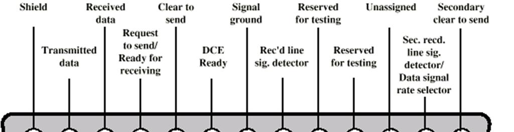
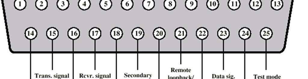
10 Mechanical Specifications -connector male/female with 25 pins, D shape, one 12 pins row, other with 13pins -male connector on DTE, female connector on DCE -mechanical specifications include: total connector s width, distance between successive pins, between pins rows, etc. 10
11 11
12 Functional Specifications 12
13 Functional Specifications Define which circuits connect to each of the 25 pins (see previous slide) 9 typically used pins: 20: Data Terminal Ready (DTE to DCE): tells that DTE is powered up and ready 6: Data Set Ready (DCE to DTE): tells DTE that DCE is powered up and ready 8: Carrier Detect (DCE to DTE): tells DTE that it detects a carrier on the line 4: Request to Send (DTE to DCE): tells DCE it wants to send data (usually for half duplex) 5: Clear to Send (DCE to DTE): tells DTE that it can accept data, usually for half duplex 2: Transmit (DTE to DCE): sends data to DCE for it to transmit 3: Receive (DCE to DTE): sends received data to DTE 1: Protective ground (for safety) 7: Signal Ground/Common Return (reference voltage for detecting signal levels) Some PCs use 9 pins connectors; pin assignment is shown in the following table. 13
14 Procedural Specifications Gives the communication rules or how s the understanding between DTE DCE, and between pairs. Sample example: an asynchronous private line modem: When turned-on and ready, modem (DCE) asserts Data Set Ready When DTE ready to send data, it asserts Request to Send Also inhibits receive mode in half duplex Modem responds when ready by asserting Clear to Send DTE sends data 9 pin Signal 25 pins 1 Carrier Detect 8 2 Received Data 3 3 Transmitted Data 2 4 Data Terminal Ready 20 5 Signal Ground 7 6 Data Set Ready 6 7 Request To Send 4 8 Clear To Send 5 9 Ring Indicator 22 When data arrives, local modem asserts Receive Line Signal Detector and delivers data 14

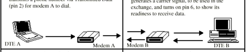
15 Dial Up Operation 15

16 Dial Up Operation cont. 16

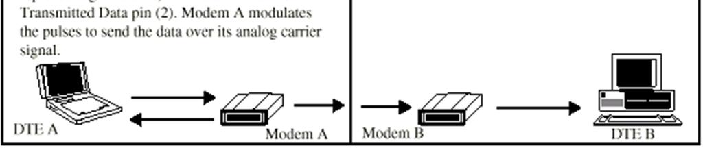
17 Dial Up Operation cont. 17
18 The wiring isn t set up to connect two DTEs together => use of null modem to cross several wires. Simplest case, the 3 wires short cable null modem, with the following architecture: Transmitted Data Received Data Request To Send Clear To Send Data Set Ready Signal Ground Data Carrier Detect Data Terminal Ready


19 Other example of null modem, with more wires, same effect! 19


, two")
20 For testing the serial interface (COM port), two simple tests: 20
21 RS 449 Standard Dates from 80s, improving the RS-232 standard, overcoming the defects. Offers backward compatibility very important, due to RS-232 huge usage => RS- 232 can be emulated by changing various connections. Consists in fact of three standards: Basic RS-449, giving mechanical, functional & procedural interfaces Electric interface given by two standards: RS-423A, similar with RS-232, using unbalanced transmission (an unique return path for all signals) RS-422A, assigns to each signal its own grounding (or, other, for each signal is provided individual return path, isolated from other grounds); so defines a balanced transmission. Gives greater DTE control over DCE, but still not exist autodialing. Mechanical connectors: 37 pins + an additional 9 pins, if secondary channel used. Provides synchronous & asynchronous transmissions Offers 10Mbps for a distance of max. 12m, and 100kbps for hundreds of meters, when using RS-422A, and 100m or 10m length, for RS-423A. Circuit description follows; remark that there are new circuits, like those used for testing! Future developments: RS-530, using balanced transmission, speed up to 2Mbps. 21
22 Mnemonics Circuit Description Mnemonics Circuit Description SG Signal Ground SC Send Common RC Receive Common IS Terminal in Service IC Incoming Call TR Terminal Ready DM Data Mode SD Send Data RD Receive Data TT Terminal Timing ST Send Timing RT Receive Timing RS Request to Send CS Clear to Send RR Receiver Ready SQ Signal Quality NS New Signal SF Select Frequency SR Signaling Rate Selector SI Signaling Rate Indicator SSD Secondary Send Data SRD Secondary Receive Data SRS Secondary Request to SCS Secondary Clear to Send Send SRR Secondary Receiver Ready LL Local Loopback RL Remote Loopback TM Test Mode SS Select Standby SB Standby Indicator 22
23 X21 Digital interface CCITT standard for direct digital connections to the digital telephone network. Uses only 8 signal lines, on a 15 pin connector, allowing use of 2 channels (A, B) Data rate fro 9600bps up to 64kbps Use of more logic, instead of more signals (RS-449) Allows bit and byte synchronization X21bis standard allows analog signalling (is a subset of RS-232D), developed for backward compatibility (use of analog telephone networks) DCE provides a full-duplex, bit-serial, synchronous transmission path between the DTE and the local PSE. Trend continued with 8-pins physical connector for ISDN (Integrated Services Digital Network) 23
24 Pin assignment and functional characteristics: 24
25 Signal Specification Signal Ground (G): protective ground (earth). DTE Common Return (Guard) for the unbalanced mode, gives reference ground for receivers in the DCE interface Transmit (T) - carry data and control from the DTE to the DCE Receive (R) - from DCE, indicates to the DTE the type of data Indication (I) controlled by DTE, indicates to the DCE the meaning of the data sent on the transmit circuit Byte Timing (B) - provides the DTE with 8-bit byte element timing Signal Element Timing (S) - provides the DTE or DCE with timing information for sampling the Receive line or Transmit line Control line (C) to DCE circuit, for extra control of DTE over DCE. 25

 ISO 8877 Cables terminate in matching connectors with 8 contacts")
26 ISDN Physical Interface Further evolution of X21 was the specification of the ISDN physical connection Connection between terminal equipment TE (c.f. DTE) and network terminating equipment NE (c.f. DCE) ISO 8877 Cables terminate in matching connectors with 8 contacts Transmit/receive lines carry both data and control 26
27 ISDN Electrical Specification Balanced transmission Signals carried on a channel made by two conductors, e.g. twisted pair Signals (as currents) travel down one conductor and up the other (return way) Differential signaling, as binary value depends on the voltage difference between lines (value depends on direction of voltage); usual differences under 1V => low power circuitry Tolerates more noise and generates less then unbalanced transmissions, because noise affects both lines, not their voltage difference (Unbalanced, e.g. RS-232, uses single signal line and a (common) ground) Data encoding depends on the data rate Basic rate 192kbps uses pseudoternary Primary rate uses alternative mark inversion (AMI) and B8ZS or HDB3 27
28 Modem Standard modem definition: The modem is the interface between a DTE (like a PC) that generates digital signals, and the telephone system that carries analog signals. Modems encode digital signals onto analog signals by modulating an analog signal by changing the phase, frequency or amplitude of the signal, to represent 1s and 0s. The method of modulation defines the modem standard. The modem receives signals from the interchange circuits, respecting the serial interface standards. 28
29 For PCs the modem may be external or internal, today s mostly internal. Even if using an internal modem, these serial interface s signals are generated by the serial interface in the modem and are recognized by the terminal emulation software. 29

30 For your Laptop with interface adapter PCMCIA slot the modem appears like: A PCMCIA modem being inserted into a laptop computer. Attached to the card is an adaptor which connects the card to a standard RJ-11 telephone line 30
31 Modem standards issued by: -Bell standards (old standards), ITU-T (former CCITT) recommendations, concerning modulation and coding techniques -EIA/TIA, ITU-T for interfaces Categories of modems: (see table on next slide) -operating speed low, medium & high speed -implemented standard -type of transmission (asynchronous, synchronous) -type of modulation (FSK, PSK, QAM) -type of telephonic lines (dial-up or leased) -complexity (traditional or smart) -other modems (ISDN modems, coax cable modems, LAN modems, wireless and cellular modems) 31
32 Data rate Standard Body Line Type Modulation Technique Transmission Type Duplex Full/Half 300 Bell 103, CCITT V21 Dial-up FSK Asynchronous Half+Full 600 CCITT V22 Dial-up/leased PSK Asynchronous Half+Full 1200 Bell 202, CCITT V22 Dial-up/leased PSK Asynch/Synch Half+Full 2400 CCITT V22bis Leased QAM Asynchronous Half+Full 4800 CCITT V27 Leased PSK Synchronous Half+Full 9600 Bell 209, CCITT V32 Dial-up/leased QAM Asynch/Synch Half+Full CCITT V32bis Dial-up/leased QAM Asynch/Synch Half+Full CCITT V34 Dial-up/leased PSK Asynch/Synch Full CCITT V90 Dial-up/leased QAM Asynchronous Full 32
33 Low speed modems First modem operated at 300 Bauds, cf. to Bell 103A standard (repeated by CCITT V21). A modem could be (vis-a-vis a transmission): -transmission originate -transmission answer Used 2 audio frequencies, one for sending and one for receiving. Ex. For Bell 103: Hz being the frequency band for originate modem data transmission and receiving band for the answering modem Hz, reception band for originate modem and emission band for answering modem. For CCITT V21 the similar frequency bands are Hz and Hz respectively. For this low speed old modem, the interface signal set comprises the following signals: RTS, CTS, DSR, DTR, DCD, RI (see RS232 signal table). 33

34 34
35 Smartmodems (Hayes compatible) Cf. RS232-C data and control lines are separated. Smartmodems understand commands and status information using characters, so no more signal separation.. Modem Commands (Hayes-compatible modem) These are commands (character strings) that the terminal emulator can send to the modem to instruct it to perform operations, such as automatic dial. Interface signal set comprises only the lines Tx (Transmit), Rx (Receive), and ground. The modem is in one of the states: -receive command from DTE -on-line -hang-up, or carrier-wait. General format of the command: AT command Where command is a letter, followed (eventually) by a parameter. The following are examples of a few of the AT (attention) commands: ATDT n: Dial phone number <n>, using touch tone ATDP n: Dial using pulse ATH: Hangup ATH1: Pick up the phone line 35
36 Introduction to: ISDN Modem ISDN (Integrated Services Digital Network), offers services on a full digital network. ISDN modems, known as TA (Terminal Adapters). An ISDN line is split in channels (see table): B (Bearer) channel carries (PCM coded digital) voice + data up to 64kbps D (data signaling) channel carries control for B channels; speed 16kbps or 64kbps Usually B and D channels use separate paths, speeding up the transmissions H (High speed) channel data transport at speeds of Mbps ITU-T defines two types of services: BRI (Basic Rate Interface), operating at 192kbps, contains 2 B channels and one D channel at 16kbps (2B + D16) PRI (Primary Rate Interface), signalling at 64kbps and operating at 1.544Mbps in US (23B + D64), or 2.048Mbps in Europe (30B + D64) Channel Bit Rate Interface B 64kbps Basic access H0 384kbps Primary rate access H kbps Primary rate access H kbps Primary rate access D16 16kbps Basic access D64 64kbps Primary rate access 36
37 Use of H channels instead of B (see table for more details): Interface Bit Rate Interface Structure Basic access Primary rate access 192 kbps 1544 kbps 2048 kbps 2B+D16 23B+D64 3H0+D64 30B+D64 5H0+D64 H12+D64 TA has similar functions as a normal modem, plus those for adapting the variable data rate of the DTE to the constant B channel data rate. Also transforms analog voice or fax data into digital. The commands for a TA have similar structure as for the smart Hayes modem (AT commands). 37
38 A little bit more about the physical level of ISDN: ISDN: First important change from analog to digital telephony, from circuit switching telephony to packet switching based Digital data exchanged between subscriber (user) and network terminal equipment (NTE) is Full Duplex => Separate physical line for each direction Pseudoternary coding scheme: 1=no voltage, 0=positive or negative 750mV +/-10% Basic rate: data rate of 192kbps, i.e. one 48 bit-long frame every 250 µs; Basic access uses synchronous TDM two 64kbps B channels and one 16kbps D channel (2B+D16) => This gives 144kbps multiplexed over 192kbps => Remaining capacity used for framing and synchronization. Use of LAP-D frames (see the following data link protocol HDLC) Two kind of frames: from/to subscriber to/from Terminal Equipment. Structure: From 48 bit: 16bit for each of B channels and 4 bit for D channel. F framing bit (positive pulse, followed by a negative one L, for dc balance F A auxiliary framing; E: D-echo channel bit (retransmission by NTE of the most received D bit; A: activation bit for NTE (allows low power-consumption mode) 38


")
39 ISDN LAP-D Frame Structure (basic access) 39
40 Primary ISDN Interface: synchronous TDM of multiple channels, allows point-topoint configurations; 2 data rates defined: DS-1 of 1.544Mbps, based on T1 trame: 24*8data bit + 1 framing, every 125 µs; 8000 frames/sec => each channel supports 64kbps; implements 23B+D64; data encoding using AMI (alternate mark inversion) B8ZS(bipolar-8 zeros substitution) E1 trame, at 2.048Mbps for 30B+D64; one 256 bit frame every 125µs, 8000 frames/sec each channel supports 64kbps; first time slot for framing and synchronization; data coded sing AMI HDB3(high density bipolar 3zeros) Primary ISDN Frame Formats 40
 at a rate beginning with 155Mbps. Transfer mode implementing B-ISDN (dealing with transmission and switching aspects) is the ATM (Asynchronous Transfer Mode).")
41 B-ISDN (Broadband ISDN) N-ISDN (Narrow ISDN) deal with 64kbps channels (type B); with H type channels (actual H channel offers tens of Mbps) => development of B-ISDN, offering a transport of packets (cells) at a rate beginning with 155Mbps. Transfer mode implementing B-ISDN (dealing with transmission and switching aspects) is the ATM (Asynchronous Transfer Mode). The ATM transport unit is the cell, small packet of 53bytes, 5 octets for control and 48 bytes payload. The protocol hierarchy of ATM is depicted below: At the Physical level, the ATM technology is based on SONET and SDH standards. 41

 Simple layout: -one-to-two splitter for transmitting TV services to set top box, and for transmitting data through cable modem to the")
42 Cable Modems Devices allowing high-speed access to the Internet via a cable television network. Even similar with voice-band modems, more than 500 times faster. Voiceband modems operate up to 56kbps, cable modems deliver 30-40Mbps of data on a 6MHz TV channel In a cable network: -data from the network to the user: downstream -data from the user to the network: upstream Downstream and upstream bandwidths may be configured after application (domestic userlow upstream bandwidth, business office may require a higher upstream band) Simple layout: -one-to-two splitter for transmitting TV services to set top box, and for transmitting data through cable modem to the computer 42


43 At the other end of the cable there is the head-end, may be a CATV provider or an ISP (Internet Service Provider), let s say a head-end point-of-presence, allowing, by use of a multiplexed network interface, the access to the Internet. User-to-network data (upstream): 5 40 MHz Television delivery (downstream): MHz Network to user data (downstream): MHz The front of a cable modem showing its various indicators. The back of a cable modem with standard coaxial television cable connector, telephone jacks and Ethernet jacks - connects the modem to a computer. 43


44 Other application with the downstream offered by CATV and upstream by cable modems. Other application, with the use of the QPSK Signal from a Cable Modem and use of a transverter, for full wireless communications using CATC antennas. 44

45 Wireless modems Many kinds of wireless modems: -RF modem for a wireless network (use of ISM bands) -cellular modem for cellular communications, attached to the phone Example: use the ISM Band for Wireless Return 900 MHz/2.4 GHz: 45
46 DSL (Digital Subscriber Line) Link between subscriber and network (local loop); tens of millions installed; Reinstall? need for exploiting the existing base of TP wired structure; initially designed for voice-grade analog transmissions with 4kHz bandwidth, TP may carry data using signals over a spectrum of more than 1MHz => use of modems for digital high rate data transmissions, using currently installed twisted pair cable. - DSL refers to the analog local loop between each customer premises and its local central office, and a DSL modem is required at each end of the loop 46
47 ADSL (Asymmetric Digital Subscriber Line) ADSL initially designed for video-on-demand, now appropriate for high-speed Internet access. Asymmetric because, from the user point, there is greater capacity downstream (from service provider to customer) than upstream. ADSL uses FDM for managing the 1MHz bandwidth: -Lowest 25kHz for voice (Plain Old Telephone Service): 0 to 4kHz for voice, rest for guard, avoiding interference with other channels -Use echo cancellation or FDM to give (to allocate) two bands: one for upstream, one for downstream -Use FDM within each of two bands. Supports loop length in the range of 5.5km. 47


48 Echo Cancellation Signal processing technique, allowing digital transmissions in both directions on a single line simultaneously. The transmitter must subtract the echo of its own transmission from the incoming signal, to recover the signal sent by the other side. Advantages: -more flexibility for upstream bandwidth changes, simply extending the area of overlap -downstream bandwidth in the good part of the spectrum (not so many HFs) => a lower attenuation 48
49 DMT (Discrete Multitone) DMT modem allows multiple carrier signals at different frequencies; -upstream and downstream bandwidths are split in a number of 4kHz sub-channels, transmitting a number of bits on each channel. Initially modem send test signal on each subchannel, and then use those subchannels with better signal to noise ratio. If used 256 downstream subchannels at 4kHz, carring data at 60kbps, will result a data rate of 15.36Mbps. Transmission impairments bring this down to 1.5Mbps to 9Mbps. Use of QAM (Quadrature Amplitude Modulation) analog signaling technique, a combination of AM and PM. May assign different number of bits/transmitted signal. Sample example: data string is split in two sub-strings. One sub-string modulates the carrier, the other modulates the carrier shifted with 90º. The composed QAM signal is the sum: s(t) = d1(t)cos 2πft + d2(t)sin 2πft. => signal has 4 states, for coding 2 bits. 49


50 xdsl recent schemes for high-data speed transmissions on ADSL High data rate DSL Single line DSL Very high data rate DSL 50
51 Alternative Broadband Access Technologies Fiber-to-the-home (FTTH) - common solution: using passive optical network (PON) - a single transceiver in the CO serving multiple customers - splitters and couplers to distribute the service among the different subscribers Cable - hybrid fiber-coax (HFC) - fiber-optic cable carrying signals between the cable headend and fiber nodes in the network, from which existing coaxial cable is used to cover the last mile to the subscribers premises. 51
52 Alternative Broadband Access Technologies Wireless - wireless local loop with the advantage that it doesn t need the installation of a transmission medium - higher frequencies systems: 20 to 40 GHz, sometimes requiring line-of-sight (LOS) availability - Lower frequency systems: 2,4GHz 5GHz, with non-los transmission BPL (Broadband over Power Line) - use of the electric power supply network for the transmission of broadband data Example: IEEE (IEEE Standard for Broadband over Power Line : Medium Access Control and Physical Layer Specifications) - high-speed (>100 Mbps at the physical layer) communication - transmission frequencies below 100 MHz - BPL devices used for the first-mile/last-mile connection (<1500 m to the premise) and BPL devices used in buildings for local area networks (LANs) and other data distribution (<100 m between devices). 52
Chapter 12: Digital Modulation and Modems
 Chapter 12: Digital Modulation and Modems MULTIPLE CHOICE 1. FSK stands for: a. Full-Shift Keying c. Full-Signal Keying b. Frequency-Shift Keying d. none of the above 2. PSK stands for: a. Pulse-Signal
DigiPoints Volume 1. Student Workbook. Module 2 Modem Overview
 Modem Overview Page 2.1 DigiPoints Volume 1 Module 2 Modem Overview Summary One of the potential advantages the cable telecommunications industry has is the ability to carry data signals at speeds significantly
William Stallings Data and Computer Communications. Chapter 8 Multiplexing. Multiplexing
 William Stallings Data and Computer Communications Chapter 8 Multiplexing Multiplexing 1 Frequency Division Multiplexing FDM Useful bandwidth of medium exceeds required bandwidth of channel Each signal
CS420/520 Axel Krings Page 1 Sequence 8
 Chapter 8: Multiplexing CS420/520 Axel Krings Page 1 Multiplexing What is multiplexing? Frequency-Division Multiplexing Time-Division Multiplexing (Synchronous) Statistical Time-Division Multiplexing,
King Fahd University of Petroleum & Minerals Computer Engineering Dept
 King Fahd University of Petroleum & Minerals Computer Engineering Dept COE 342 Data and Computer Communications Term 021 Dr. Ashraf S. Hasan Mahmoud Rm 22-144 Ext. 1724 Email: ashraf@ccse.kfupm.edu.sa
The Last Mile Problem
 The Last Mile Problem LAN, MAN, WAN how to connect private users at home to such networks? Problem of the last mile: somehow connect private homes to the public Internet without laying many new cables
Data and Computer Communications. Tenth Edition by William Stallings
 Data and Computer Communications Tenth Edition by William Stallings Data and Computer Communications, Tenth Edition by William Stallings, (c) Pearson Education, 2013 CHAPTER 8 Multiplexing It was impossible
The Physical Layer Outline
 The Physical Layer Outline Theoretical Basis for Data Communications Digital Modulation and Multiplexing Guided Transmission Media (copper and fiber) Public Switched Telephone Network and DSLbased Broadband
Data Transmission via Modem. The Last Mile Problem. Modulation of Digital Signals. Modem Standards (CCITT)
") The Last Mile Problem LN, MN, WN how to connect private users at home to such networks? Problem of the last mile: somehow connect private homes to the public Internet without laying many new cables By
The Last Mile Problem LN, MN, WN how to connect private users at home to such networks? Problem of the last mile: somehow connect private homes to the public Internet without laying many new cables By
ITL Basics of Encoding and Wiring
 ITL Basics of Encoding and Wiring Objectives Quick overview of wide-area communications Define the term Structured Wiring Define "analog" and "digital" data. List the common methods used to encode analog/digital
ROM/UDF CPU I/O I/O I/O RAM
 DATA BUSSES INTRODUCTION The avionics systems on aircraft frequently contain general purpose computer components which perform certain processing functions, then relay this information to other systems.
CSCD 433 Network Programming Fall Lecture 5 Physical Layer Continued
 CSCD 433 Network Programming Fall 2016 Lecture 5 Physical Layer Continued 1 Topics Definitions Analog Transmission of Digital Data Digital Transmission of Analog Data Multiplexing 2 Different Types of
ANALOG AND DIGITAL PHYSICAL INTERFACES
 ANALOG AND DIGITAL PHYSICAL INTERFACES Habib Youssef, Ph.D youssef@ccse.kfupm.edu.sa Department of Computer Engineering King Fahd University of Petroleum and Minerals Dhahran, Saudi Arabia COMPUTER NETWORK
ET4254 Communications and Networking 1
 Topic 5 Look at multiplexing multiple channels on a single link FDM TDM Statistical TDM ASDL and xdsl 1 Multiplexing multiple links on 1 physical line common on long-haul, high capacity, links have FDM,
Data and Computer Communications. Tenth Edition by William Stallings
 Data and Computer Communications Tenth Edition by William Stallings Data and Computer Communications, Tenth Edition by William Stallings, (c) Pearson Education - Prentice Hall, 2013 CHAPTER 8 Multiplexing
CPSC Network Programming. How do computers really communicate?
 CPSC 360 - Network Programming Data Transmission Michele Weigle Department of Computer Science Clemson University mweigle@cs.clemson.edu February 11, 2005 http://www.cs.clemson.edu/~mweigle/courses/cpsc360
a. Find the minimum number of samples per second needed to recover the signal without loosing information.
 1. The digital signal X(t) given below. X(t) 1 0 1 2 3 4 5 7 8 t (msec) a. If the carrier is sin (2000 π t), plot Amplitude Shift Keying (ASK) Modulated signal. b. If digital level 1 is represented by
Multiplexing. Chapter 8. Frequency Division Multiplexing Diagram. Frequency Division Multiplexing. Multiplexing
 Multiplexing Chapter 8 Multiplexing Frequency Division Multiplexing FDM Useful bandwidth of medium exceeds required bandwidth of channel Each signal is modulated to a different carrier frequency Carrier
EE 304 TELECOMMUNICATIONs ESSENTIALS HOMEWORK QUESTIONS AND ANSWERS
 Homework Question 1 EE 304 TELECOMMUNICATIONs ESSENTIALS HOMEWORK QUESTIONS AND ANSWERS Allocated channel bandwidth for commercial TV is 6 MHz. a. Find the maximum number of analog voice channels that
Signal Encoding Techniques
 2 Techniques ITS323: to Data Communications CSS331: Fundamentals of Data Communications Sirindhorn International Institute of Technology Thammasat University Prepared by Steven Gordon on 3 August 2015
Digital Communication Systems. Asymmetric Digital Subscriber Line (ADSL) Gavin Cameron
 Gavin Cameron") Digital Communication Systems Asymmetric Digital Subscriber Line (ADSL) Gavin Cameron MSc/PGD Electronics and Communication Engineering May 17, 2000 TABLE OF CONTENTS TABLE OF CONTENTS..........................................................
Digital Communication Systems Asymmetric Digital Subscriber Line (ADSL) Gavin Cameron MSc/PGD Electronics and Communication Engineering May 17, 2000 TABLE OF CONTENTS TABLE OF CONTENTS..........................................................
CSCD 433 Network Programming Fall Lecture 5 Physical Layer Continued
 CSCD 433 Network Programming Fall 2016 Lecture 5 Physical Layer Continued 1 Topics Definitions Analog Transmission of Digital Data Digital Transmission of Analog Data Multiplexing 2 Different Types of
Data Communications and Networking (Module 2)
") Data Communications and Networking (Module 2) Chapter 5 Signal Encoding Techniques References: Book Chapter 5 Data and Computer Communications, 8th edition, by William Stallings 1 Outline Overview Encoding
Data Communications and Networking (Module 2) Chapter 5 Signal Encoding Techniques References: Book Chapter 5 Data and Computer Communications, 8th edition, by William Stallings 1 Outline Overview Encoding
Concept of Serial Communication
 Concept of Serial Communication Agenda Serial v.s. Parallel Simplex, Half Duplex, Full Duplex Communication RS-485 Advantage over RS-232 Serial v.s. Parallel Application: How to Measure the temperature
INTRODUCTION TO COMMUNICATION SYSTEMS AND TRANSMISSION MEDIA
 COMM.ENG INTRODUCTION TO COMMUNICATION SYSTEMS AND TRANSMISSION MEDIA 9/9/2017 LECTURES 1 Objectives To give a background on Communication system components and channels (media) A distinction between analogue
SEN366 Computer Networks
 SEN366 Computer Networks Prof. Dr. Hasan Hüseyin BALIK (5 th Week) 5. Signal Encoding Techniques 5.Outline An overview of the basic methods of encoding digital data into a digital signal An overview of
NETWORK. TE = Terminal Equipment (DTE - Data Terminal Equipment) NT = Network - Terminating Equipment (DCE - Data Circuit - Terminating Equipment)
 NT = Network - Terminating Equipment (DCE - Data Circuit - Terminating Equipment)") NETWORK INTERFACING TE NT NETWORK NT TE Interface Interface TE = Terminal Equipment (DTE - Data Terminal Equipment) NT = Network - Terminating Equipment (DCE - Data Circuit - Terminating Equipment) Interface
NETWORK INTERFACING TE NT NETWORK NT TE Interface Interface TE = Terminal Equipment (DTE - Data Terminal Equipment) NT = Network - Terminating Equipment (DCE - Data Circuit - Terminating Equipment) Interface
(Refer Slide Time: 2:23)
") Data Communications Prof. A. Pal Department of Computer Science & Engineering Indian Institute of Technology, Kharagpur Lecture-11B Multiplexing (Contd.) Hello and welcome to today s lecture on multiplexing
Data Communications Prof. A. Pal Department of Computer Science & Engineering Indian Institute of Technology, Kharagpur Lecture-11B Multiplexing (Contd.) Hello and welcome to today s lecture on multiplexing
Introduction to Wireless Networking CS 490WN/ECE 401WN Winter 2007
 Introduction to Wireless Networking CS 490WN/ECE 401WN Winter 2007 Lecture 9: WiMax and IEEE 802.16 Chapter 11 Cordless Systems and Wireless Local Loop I. Cordless Systems (Section 11.1) This section of
Data and Computer Communications Chapter 8 Multiplexing
 Data and Computer Communications Chapter 8 Multiplexing Eighth Edition by William Stallings 1 Multiplexing multiple links on 1 physical line common on long-haul, high capacity, links have FDM, TDM, STDM
Data Communication (CS601)
") Data Communication (CS601) MOST LATEST (2012) PAPERS For MID Term (ZUBAIR AKBAR KHAN) Page 1 Q. Suppose a famous Telecomm company AT&T is using AMI encoding standard for its digital telephone services,
Data Communication (CS601) MOST LATEST (2012) PAPERS For MID Term (ZUBAIR AKBAR KHAN) Page 1 Q. Suppose a famous Telecomm company AT&T is using AMI encoding standard for its digital telephone services,
CS601 Data Communication Solved Objective For Midterm Exam Preparation
 CS601 Data Communication Solved Objective For Midterm Exam Preparation Question No: 1 Effective network mean that the network has fast delivery, timeliness and high bandwidth duplex transmission accurate
CHAPTER 5 TRANSMISSION OF DIGITAL DATA INTERFACES & MODEMS
 CHAPTER 5 TRANSMISSION OF DIGITAL DATA INTERFACES & MODEMS Information generated by a source need to be encoded into a suitable format for transmission. To transmit the encoded signals generated by the
Data Communications and Networks
 Data Communications and Networks Engr. Abdul Rahman Mahmood MS, MCP, QMR(ISO9001:2000) Usman Institute of Technology University Road, Karachi armahmood786@yahoo.com alphasecure@gmail.com alphapeeler.sf.net/pubkeys/pkey.htm
Making Connections Efficient: Multiplexing and Compression
 Fundamentals of Networking and Data Communications, Sixth Edition 5-1 Making Connections Efficient: Multiplexing and Compression Chapter 5 Learning Objectives After reading this chapter, students should
MODULE IV. End Sem. Exam Marks. Syllabus
 MODULE IV Syllabus Multiplexing- Space Division Multiplexing, Frequency Division Multiplexing, Wave length Division Multiplexing - Time Division multiplexing: Characteristics, Digital Carrier system, SONET/SDH,
CS601-Data Communication Latest Solved Mcqs from Midterm Papers
 CS601-Data Communication Latest Solved Mcqs from Midterm Papers May 07,2011 Lectures 1-22 Moaaz Siddiq Latest Mcqs MIDTERM EXAMINATION Spring 2010 Question No: 1 ( Marks: 1 ) - Please choose one Effective
Overview. Chapter 4. Design Factors. Electromagnetic Spectrum
 Chapter 4 Transmission Media Overview Guided - wire Unguided - wireless Characteristics and quality determined by medium and signal For guided, the medium is more important For unguided, the bandwidth
ADSL. Surasak Sanguanpong Last updated: 9 Feb 2001
 1/6 Surasak Sanguanpong nguan@ku.ac.th http://www.cpe.ku.ac.th/~nguan Last updated: 9 Feb 2001 What is? 2/6 stands for Asymmetric Digital Subscriber Line is a new, super high-speed modem technology that
ECE 271 INTRODUCTION TO TELECOMMUNICATION NETWORKS HOMEWORK QUESTIONS ECE 271 HOMEWORK-1
 ECE 271 INTRODUCTION TO TELECOMMUNICATION NETWORKS HOMEWORK QUESTIONS Homework Question 1 ECE 271 HOMEWORK-1 Allocated channel bandwidth for commercial TV is 6 MHz. a. Find the maximum number of analog
Optical Fiber Communications p. 1 Introduction p. 1 History of Optical Fibers p. 1 Optical Fibers Versus Metallic Cable Facilities p.
 Optical Fiber Communications p. 1 Introduction p. 1 History of Optical Fibers p. 1 Optical Fibers Versus Metallic Cable Facilities p. 2 Advantages of Optical Fiber Systems p. 3 Disadvantages of Optical
Wireless Communications
 2. Physical Layer DIN/CTC/UEM 2018 Periodic Signal Periodic signal: repeats itself in time, that is g(t) = g(t + T ) in which T (given in seconds [s]) is the period of the signal g(t) The number of cycles
6. has units of bits/second. a. Throughput b. Propagation speed c. Propagation time d. (b)or(c)
or(c)") King Saud University College of Computer and Information Sciences Information Technology Department First Semester 1436/1437 IT224: Networks 1 Sheet# 10 (chapter 3-4-5) Multiple-Choice Questions 1. Before
King Saud University College of Computer and Information Sciences Information Technology Department First Semester 1436/1437 IT224: Networks 1 Sheet# 10 (chapter 3-4-5) Multiple-Choice Questions 1. Before
APPLICATION BULLETIN. SERIAL BACKGROUNDER (Serial 101) AB23-1. ICS ICS ELECTRONICS division of Systems West Inc. INTRODUCTION CHAPTER 2 - DATA FORMAT
 AB23-1. ICS ICS ELECTRONICS division of Systems West Inc. INTRODUCTION CHAPTER 2 - DATA FORMAT") ICS ICS ELECTRONICS division of Systems West Inc. AB- APPLICATION BULLETIN SERIAL BACKGROUNDER (Serial 0) INTRODUCTION Serial data communication is the most common means of transmitting data from one point
ICS ICS ELECTRONICS division of Systems West Inc. AB- APPLICATION BULLETIN SERIAL BACKGROUNDER (Serial 0) INTRODUCTION Serial data communication is the most common means of transmitting data from one point
USER'S MANUAL. Model : K
 USER'S MANUAL Model : 2000-64K TM GINA MODEL 2000-64K Overview GINA Model 2000-64K is a stand-alone, high frequency data transceiver using spread spectrum technology. GINA 2000-64K capabilities include
Chapter 4 Digital Transmission 4.1
 Chapter 4 Digital Transmission 4.1 Copyright The McGraw-Hill Companies, Inc. Permission required for reproduction or display. 4-1 DIGITAL-TO-DIGITAL CONVERSION In this section, we see how we can represent
Announcements : Wireless Networks Lecture 3: Physical Layer. Bird s Eye View. Outline. Page 1
 Announcements 18-759: Wireless Networks Lecture 3: Physical Layer Please start to form project teams» Updated project handout is available on the web site Also start to form teams for surveys» Send mail
OFDMA and MIMO Notes
 OFDMA and MIMO Notes EE 442 Spring Semester Lecture 14 Orthogonal Frequency Division Multiplexing (OFDM) is a digital multi-carrier modulation technique extending the concept of single subcarrier modulation
Electronics / Water analogy. Resistor. Inductance. Capacitor. Water Electronics Energy - Energy Pressure - Voltage Flow - Current Volume - Charge
 Electronics / Water analogy Water Electronics Energy - Energy Pressure - Voltage Flow - Current Volume - Charge Resistor U = R * I 1 Capacitor U 1 i dt C U L di dt Inductance Turbine Flywheel Diode Transistor
CSMC 417. Computer Networks Prof. Ashok K Agrawala Ashok Agrawala Set 3
 CSMC 417 Computer Networks Prof. Ashok K Agrawala 2013 Ashok Agrawala Set 3 The Physical Layer Foundation on which other layers build Properties of wires, fiber, wireless limit what the network can do
SOME PHYSICAL LAYER ISSUES. Lecture Notes 2A
 SOME PHYSICAL LAYER ISSUES Lecture Notes 2A Delays in networks Propagation time or propagation delay, t prop Time required for a signal or waveform to propagate (or move) from one point to another point.
Lecture 3 Concepts for the Data Communications and Computer Interconnection
 Lecture 3 Concepts for the Data Communications and Computer Interconnection Aim: overview of existing methods and techniques Terms used: -Data entities conveying meaning (of information) -Signals data
Appendix C T1 Overview
 Appendix C T Overview GENERAL T refers to the primary digital telephone carrier system used in North America. T is one line type of the PCM T-carrier hierarchy listed in Table C-. T describes the cabling,
Politecnico di Milano Scuola di Ingegneria Industriale e dell Informazione. Physical layer. Fundamentals of Communication Networks
 Politecnico di Milano Scuola di Ingegneria Industriale e dell Informazione Physical layer Fundamentals of Communication Networks 1 Disclaimer o The basics of signal characterization (in time and frequency
TELECOMMUNICATION SYSTEMS
 TELECOMMUNICATION SYSTEMS By Syed Bakhtawar Shah Abid Lecturer in Computer Science 1 MULTIPLEXING An efficient system maximizes the utilization of all resources. Bandwidth is one of the most precious resources
INTERNATIONAL TELECOMMUNICATION UNION
 INTERNATIONAL TELECOMMUNICATION UNION CCITT G.703 THE INTERNATIONAL TELEGRAPH AND TELEPHONE CONSULTATIVE COMMITTEE (11/1988) SERIE G: TRANSMISSION SYSTEMS AND MEDIA, DIGITAL SYSTEMS AND NETWORKS General
Contents. Telecom Systems Chae Y. Lee. FDM Bell Systems s FDM Synchronous TDM T1, T3 Statistical TDM Multiple Access: FDMA, TDMA, CDMA
 Multiplexing Contents FDM Bell Systems s FDM Synchronous TDM T1, T3 Statistical TDM Multiple Access: FDMA, TDMA, CDMA 2 Multiplexing/Demultiplexing Multiplexing is the process of combining two or more
Mobile Communication Systems. Part 7- Multiplexing
 Mobile Communication Systems Part 7- Multiplexing Professor Z Ghassemlooy Faculty of Engineering and Environment University of Northumbria U.K. http://soe.ac.uk/ocr Contents Multiple Access Multiplexing
Cable Testing TELECOMMUNICATIONS AND NETWORKING
 Cable Testing TELECOMMUNICATIONS AND NETWORKING Analog Signals 2 Digital Signals Square waves, like sine waves, are periodic. However, square wave graphs do not continuously vary with time. The wave holds
The Physical Layer Chapter 2. The Physical Layer
 The Physical Layer Chapter 2 Theoretical Basis for Data Communications Guided Transmission Media Wireless Transmission Communication Satellites Digital Modulation and Multiplexing Public Switched Telephone
CHAPTER 2. Instructor: Mr. Abhijit Parmar Course: Mobile Computing and Wireless Communication ( )
") CHAPTER 2 Instructor: Mr. Abhijit Parmar Course: Mobile Computing and Wireless Communication (2170710) Syllabus Chapter-2.3 Modulation Techniques Reasons for Choosing Encoding Techniques Digital data,
CHAPTER 2 Instructor: Mr. Abhijit Parmar Course: Mobile Computing and Wireless Communication (2170710) Syllabus Chapter-2.3 Modulation Techniques Reasons for Choosing Encoding Techniques Digital data,
Bluetooth BlueTooth - Allows users to make wireless connections between various communication devices such as mobile phones, desktop and notebook comp
 ECE 271 Week 8 Bluetooth BlueTooth - Allows users to make wireless connections between various communication devices such as mobile phones, desktop and notebook computers - Uses radio transmission - Point-to-multipoint
Guide to Wireless Communications, Third Edition Cengage Learning Objectives
 Guide to Wireless Communications, Third Edition Chapter 9 Wireless Metropolitan Area Networks Objectives Explain why wireless metropolitan area networks (WMANs) are needed Describe the components and modes
ECE 435 Network Engineering Lecture 4
 ECE 435 Network Engineering Lecture 4 Vince Weaver http://web.eece.maine.edu/~vweaver vincent.weaver@maine.edu 12 September 2016 Announcements Homework 2 was posted late, due next Monday Homework 1 grades
Outline / Wireless Networks and Applications Lecture 3: Physical Layer Signals, Modulation, Multiplexing. Cartoon View 1 A Wave of Energy
 Outline 18-452/18-750 Wireless Networks and Applications Lecture 3: Physical Layer Signals, Modulation, Multiplexing Peter Steenkiste Carnegie Mellon University Spring Semester 2017 http://www.cs.cmu.edu/~prs/wirelesss17/
Unbounded Transmission Media
 Unbounded Transmission Media Unbounded Media The three main types of wireless media are Radio Microwave infrared Electromagnetic spectrum for wireless communication Unguided waves can travel from source
Bandwidth Utilization:
 CHAPTER 6 Bandwidth Utilization: In real life, we have links with limited bandwidths. The wise use of these bandwidths has been, and will be, one of the main challenges of electronic communications. However,
CS441 Mobile & Wireless Computing Communication Basics
 Department of Computer Science Southern Illinois University Carbondale CS441 Mobile & Wireless Computing Communication Basics Dr. Kemal Akkaya E-mail: kemal@cs.siu.edu Kemal Akkaya Mobile & Wireless Computing
PRODUCT INFORMATION B&B ELECTRONICS. Port-Powered RS-232 Fiber Optic Modem with Handshake Support. Model 9PFLST. Description. RS-232 Connections
 -01-1/ 00 by B&B Electronics. All rights reserved. Model Port-Powered RS- Fiber Optic Modem with Handshake Support Description The allows any two pieces of RS- asynchronous serial equipment to communicate
Telecommunication Network The Fundamental
 Telecommunication Network The Fundamental Course Number : TTH2A3 CLO : 1 Week : 1 Why do we need to take this course? List of countries by number of telephone lines in use Rankings Country or regions Number
Computer Networks
 15-441 Computer Networks Physical Layer Professor Hui Zhang hzhang@cs.cmu.edu 1 Communication & Physical Medium There were communications before computers There were communication networks before computer
VC-4/4A, VC-8/8A, VC-16 4/8/16-Channel PCM and ADPCM Voice Modules
 4, 8 or 16 analog voice channels using 64 kbps toll-quality PCM encoding; 24/32 kbps ADPCM encoding option for 4- and 8-channel modules E&M, FXS or FXO interface options Caller ID A-law or μ-law companding
IEEE P Broadband Wireless Access Working Group
 Project Title Date Submitted Source Re: Abstract Purpose Notice Release IEEE P802.16 Broadband Wireless Access Working Group Contribution to the 802.16 System Requirements Document on the Issue of The
This is by far the most ideal method, but poses some logistical problems:
 NXU to Help Migrate to New Radio System Purpose This Application Note will describe a method at which NXU Network extension Units can aid in the migration from a legacy radio system to a new, or different
Question Paper Profile
 Question Paper Profile Max. Marks : 70 Time: 3 Hrs. Q.1) A) Attempt any FIVE of the following. 10 Marks a) Define the term Standard. State its two categories. b) List any two advantages of Unguided Media.
UNIT 6 ANALOG COMMUNICATION & MULTIPLEXING YOGESH TIWARI EC DEPT,CHARUSAT
 UNIT 6 ANALOG COMMUNICATION & MULTIPLEXING YOGESH TIWARI EC DEPT,CHARUSAT Syllabus Multiplexing, Frequency-Division Multiplexing Time-Division Multiplexing Space-Division Multiplexing Combined Modulation
Multiplexing. Dr. Manas Khatua Assistant Professor Dept. of CSE IIT Jodhpur
 CS311: DATA COMMUNICATION Multiplexing Dr. Manas Khatua Assistant Professor Dept. of CSE IIT Jodhpur e-mail: manaskhatua@iitj.ac.in Outline of the Lecture What is Multiplexing and why is it used? Basic
EITF25 Internet Techniques and Applications L2: Physical layer. Stefan Höst
 EITF25 Internet Techniques and Applications L2: Physical layer Stefan Höst Data vs signal Data: Static representation of information For storage Signal: Dynamic representation of information For transmission
Outline of the Lecture
 CS311: DATA COMMUNICATION Multiplexing by Dr. Manas Khatua Assistant Professor Dept. of CSE IIT Jodhpur E-mail: manaskhatua@iitj.ac.in Web: http://home.iitj.ac.in/~manaskhatua http://manaskhatua.github.io/
Computer Networks: Multiplexing
 Computer Networks: Multiplexing EE1001 Prof. Taek M. Kwon Department of Electrical Engineering, UMD Outline EE 4321 Multiplexing EE 4321: Computer Networks EE Technical Elective Course, 3 credits Network
PHYSICAL/ELECTRICAL CHARACTERISTICS OF HIERARCHICAL DIGITAL INTERFACES. (Geneva, 1972; further amended)
") 5i Recommendation G.703 PHYSICAL/ELECTRICAL CHARACTERISTICS OF HIERARCHICAL DIGITAL INTERFACES (Geneva, 1972; further amended) The CCITT, considering that interface specifications are necessary to enable
5i Recommendation G.703 PHYSICAL/ELECTRICAL CHARACTERISTICS OF HIERARCHICAL DIGITAL INTERFACES (Geneva, 1972; further amended) The CCITT, considering that interface specifications are necessary to enable
Signal Encoding Techniques
 Signal Encoding Techniques Overview Have already noted previous chapters that both analog and digital information can be encoded as either analog or digital signals: Digital data, digital signals: simplest
Bandwidth utilization is the wise use of available bandwidth to achieve specific goals.
 Note Bandwidth Utilization: Multiplexing and Spreading Bandwidth utilization is the wise use of available bandwidth to achieve specific goals. Efficiency can be achieved by multiplexing; i.e., sharing
Analog and Digital Transmission Interfaces & Multiplexing (Physical Layer) Class 3 Overview
 Class 3 Overview") CS656: Computer Networks Analog and Digital Transmission Interfaces & Multiplexing (Physical Layer) Class 3 19:20 to 22:00 10 Sep 2002 The author of these slides is Dr. Mark Pullen of George Mason University.
CS656: Computer Networks Analog and Digital Transmission Interfaces & Multiplexing (Physical Layer) Class 3 19:20 to 22:00 10 Sep 2002 The author of these slides is Dr. Mark Pullen of George Mason University.
Chapter 2. Bandwidth-Limited Signals (2) The Theoretical Basis for Data Communication
 The Theoretical Basis for Data Communication") Chapter 2 The Physical Layer The Theoretical Basis for Data Communication Fourier Analysis Bandwidth-Limited Signals Maximum Data Rate of a Channel Bandwidth-Limited Signals Bandwidth-Limited Signals (2)
Chapter 2 The Physical Layer The Theoretical Basis for Data Communication Fourier Analysis Bandwidth-Limited Signals Maximum Data Rate of a Channel Bandwidth-Limited Signals Bandwidth-Limited Signals (2)
Part IV: Glossary of Terms
 Issue 9 November 2004 Spectrum Management and Telecommunications Policy Compliance Specification for Terminal Equipment, Terminal Systems, Network Protection Devices, Connection Arrangements and Hearing
EECE494: Computer Bus and SoC Interfacing. Serial Communication: RS-232. Dr. Charles Kim Electrical and Computer Engineering Howard University
 EECE494: Computer Bus and SoC Interfacing Serial Communication: RS-232 Dr. Charles Kim Electrical and Computer Engineering Howard University Spring 2014 1 Many types of wires/pins in the communication
PRINCIPLES OF COMMUNICATION SYSTEMS. Lecture 1- Introduction Elements, Modulation, Demodulation, Frequency Spectrum
 PRINCIPLES OF COMMUNICATION SYSTEMS Lecture 1- Introduction Elements, Modulation, Demodulation, Frequency Spectrum Topic covered Introduction to subject Elements of Communication system Modulation General
Chapter 3 Digital Transmission Fundamentals
 Chapter 3 Digital Transmission Fundamentals Digital Representation of Information Why Digital Communications? Digital Representation of Analog Signals Characterization of Communication Channels Fundamental
Model 4xx. Plug-in Series Of FSK Modems USER GUIDE. (TI) 20 Jan 06 DWG: A GDI COMMUNICATIONS LLC PO Box I-80 Exit 1 Verdi, NV 89439
 20 Jan 06 DWG: A GDI COMMUNICATIONS LLC PO Box I-80 Exit 1 Verdi, NV 89439") Model 4xx Plug-in Series Of FSK s USER GUIDE (TI) 20 Jan 06 DWG: A01164 GDI COMMUNICATIONS LLC PO Box 1330 280 I-80 Exit 1 Verdi, NV 89439 Phone: (775) 345-8000 Fax: (775) 345-8010 Web: www.sgdi.com Email:
Model 4xx Plug-in Series Of FSK s USER GUIDE (TI) 20 Jan 06 DWG: A01164 GDI COMMUNICATIONS LLC PO Box 1330 280 I-80 Exit 1 Verdi, NV 89439 Phone: (775) 345-8000 Fax: (775) 345-8010 Web: www.sgdi.com Email:
Chapter 6 Bandwidth Utilization: Multiplexing and Spreading 6.1
 Chapter 6 Bandwidth Utilization: Multiplexing and Spreading 6.1 Copyright The McGraw-Hill Companies, Inc. Permission required for reproduction or display. 3-6 PERFORMANCE One important issue in networking
RECOMMENDATION ITU-R F.756 * TDMA point-to-multipoint systems used as radio concentrators
 Rec. ITU-R F.756 1 RECOMMENDATION ITU-R F.756 * TDMA point-to-multipoint systems used as radio concentrators (Question ITU-R 125/9) (1992) The ITU Radiocommunication Assembly, considering a) that analogue
Wireless WANS and MANS. Chapter 3
 Wireless WANS and MANS Chapter 3 Cellular Network Concept Use multiple low-power transmitters (100 W or less) Areas divided into cells Each served by its own antenna Served by base station consisting of
Announcement : Wireless Networks Lecture 3: Physical Layer. A Reminder about Prerequisites. Outline. Page 1
 Announcement 18-759: Wireless Networks Lecture 3: Physical Layer Peter Steenkiste Departments of Computer Science and Electrical and Computer Engineering Spring Semester 2010 http://www.cs.cmu.edu/~prs/wirelesss10/
DATA TRANSMISSION. ermtiong. ermtiong
 DATA TRANSMISSION Analog Transmission Analog signal transmitted without regard to content May be analog or digital data Attenuated over distance Use amplifiers to boost signal Also amplifies noise DATA
P. 241 Figure 8.1 Multiplexing
 CH 08 : MULTIPLEXING Multiplexing Multiplexing is multiple links on 1 physical line To make efficient use of high-speed telecommunications lines, some form of multiplexing is used It allows several transmission
ECE 4510/5530 Microcontroller Applications Week 6 Lab 5
 Microcontroller Applications Week 6 Lab 5 Dr. Bradley J. Bazuin Associate Professor Department of Electrical and Computer Engineering College of Engineering and Applied Sciences Lab 5 Element Hardware
CSE 123: Computer Networks Alex C. Snoeren. Project 1 out Today, due 10/26!
 CSE 123: Computer Networks Alex C. Snoeren Project 1 out Today, due 10/26! Signaling Types of physical media Shannon s Law and Nyquist Limit Encoding schemes Clock recovery Manchester, NRZ, NRZI, etc.
xdsl Modulation Techniques
 NEXTEP Broadband White Paper xdsl Modulation Techniques Methods of achieving spectrum-efficient modulation for high quality transmissions. A Nextep Broadband White Paper May 2001 Broadband Networks Group
William Stallings Data and Computer Communications. Bab 4 Media Transmisi
 William Stallings Data and Computer Communications Bab 4 Media Transmisi Overview Guided - wire Unguided - wireless Characteristics and quality determined by medium and signal For guided, the medium is