Design of synthetic aperture sonar systems for high-resolution seabed imaging (tutorial slides)
|
|
|
- Wilfrid Oliver
- 5 years ago
- Views:
Transcription
1 Reprint Series NURC-PR Design of synthetic aperture sonar systems for high-resolution seabed imaging (tutorial slides) Marc Pinto October 2006 Originally presented as a tutorial at : OCEANS 06 MTS/IEEE Boston, Massachussets, USA, September 2006
2 (NURC) NURC conducts world class maritime research in support of NATO's operational and transformational requirements. Reporting to the Supreme Allied Commander Transformation, the Centre maintains extensive partnering to expand its research output, promote maritime innovation and foster more rapid implementation of research products. The Scientific Programme of Work (SPOW) is the core of the Centre's activities and is organized into four Research Thrust Areas: Expeditionary Mine Countermeasures (MCM) and Port Protection (EMP) Reconnaissance, Surveillance and Undersea Networks (RSN) Expeditionary Operations Support (EOS) Command and Operational Support (COS) NURC also provides services to other sponsors through the Supplementary Work Program (SWP). These activities are undertaken to accelerate implementation of new military capabilities for NATO and the Nations, to provide assistance to the Nations, and to ensure that the Centre s maritime capabilities are sustained in a fully productive and economic manner. Examples of supplementary work include ship chartering, military experimentation, collaborative work with or services to Nations and industry. NURC s plans and operations are extensively and regularly reviewed by outside bodies including peer review of the research, independent national expert oversight, review of proposed deliverables by military user authorities, and independent business process certification. The Scientific Committee of National Representatives, membership of which is open to all NATO nations, provides scientific guidance to the Centre and the Supreme Allied Commander Transformation. Copyright NATO Undersea Research Centre NATO member nations have unlimited rights to use, modify, reproduce, release, perform, display or disclose these materials, and to authorize others to do so for government purposes. Any reproductions marked with this legend must also reproduce these markings. All other rights and uses except those permitted by copyright law are reserved by the copyright owner. NOTE: The NURC Reprint series reprints papers and articles published by NURC authors in the open literature as an effort to widely disseminate NURC products. Users are encouraged to cite the original article where possible.
3 Design of synthetic aperture sonar systems for high-resolution seabed imaging Editorial Note: This reprint is a compilation of the slides presented at the OCEANS 06 tutorial of the same title above. Summary of the tutorial This tutorial reviews the key aspects of the design of synthetic aperture sonar (SAS) systems for high resolution seabed imaging. After a quick overview of the expected benefits and main features of SAS, the design of the transmitter and receiver arrays is discussed, with emphasis on the mitigation of spatial aliasing with multi-element receiver arrays, wideband operation and extension to interferometric SAS for estimating the seabed bathymetry. The most difficult issue in SAS, which is the micronavigation problem, i.e. estimating the unwanted platform motions with the required sub-wavelength accuracy, will be addressed in detail. The emphasis is on methods that have proven their value at sea, which combine inertial navigation systems (INS) with data-driven methods based on the Displaced Phase Centre Antenna (DPCA) technique. The topics covered include: the theory of spatial backscatter coherence, the derivation of ping to ping motion estimates using time delay estimation theory, including the use of bandwidth for phase unwrapping and the appropriate rangedependent near field corrections to arrive at unbiased estimates, the establishment of the Cramer Rao lower bounds for motion estimation which demonstrate the need for fusion with an INS to achieve full performance. The geometrical relationship between the DPCA and INS projection frames, which is necessary for accurate fusion, will be established and shown to depend also on the local seabed slope. The estimation of this slope with interferometric sonar is discussed. Furthermore the impact of the environment, and in particular of the multipath structure in large range to water depth ratios is discussed. Multipath is shown to degrade the quality of the SAS imagery as well as adversely impact the accuracy of interferometric estimates including DPCA. Means to mitigate multipath operation by management of the vertical transmission and reception beams is discussed, showing experimental results which point to some of the limitations of existing sonar performance prediction tools. Finally different design trade-offs between computational efficiency and robustness for micronavigated SAS imaging algorithms is discussed, and an example of a real-time implementation suited for operation on-board an autonomous underwater vehicle will be described.
4 About the presenter Marc Pinto was born in Wellington, India in He graduated from the Ecole Nationale des Ponts et Chaussées, Paris (France) in From 1985 to 1989 and 1989 to 1993 he worked as a research engineer for Thomson-CSF, specializing in the development of finite element techniques for solving non-linear magnetostatics to support the modeling of the magnetic recording process. In 1991, he received the Ph.D. degree in Solid State Physics from the University of Paris, Orsay. In 1993 he joined Thomson-Sintra ASM (now Thales Underwater Systems) as Head of the Signal Processing Group, specializing in research into advanced MCM and airborne ASW sonar. Dr Pinto joined the NATO Saclant Undersea Research Center, La Spezia, Italy in 1997 as principal scientist. He was appointed Head of the Mine Countermeasures Group, in the Signal and Systems Division in 1998 and held this position until the Group was dissolved in From 2000 to 2004, as project leader, he conducted research into synthetic aperture sonar systems for hunting proud and buried mines. In 2004 he was appointed Head of the Expeditionary MCM and Port Protection Department where he presently oversees the research into AUV-based minehunting, electronic mine countermeasures and harbour defence.


5 NATO Undersea Research Centre Partnering for Maritime Innovation Synthetic Aperture Sonar Tutorial Marc Pinto NATO Undersea Research Centre Overview I. SAS array design II. SAS micronavigation III. Impact of the shallow water environment on SAS IV. Applications Tutorial presented at Oceans 06 NURC 1 1
6 I. SAS array design Benefit of SAS for high resolution imaging Single-element SAS SAS beamforming: principle & examples Ambiguities & spatial sampling Relation to Doppler processing Phase Centre Approximation Multi-element SAS design Multi-aspect SAS Tutorial presented at Oceans 06 NURC 2 Benefit of SAS Today s technology offers very high range resolution using wideband pulses: c RR = 2 B High cross-range resolution (CRR) is difficult to obtain with real aperture sonar (RAS): CRR λ = r L Sound absorption set the limit on minimum λ. Platform size sets the limit on maximum L. CRR increases with range r. SAS will allow CRR independent of λ & r with practical platform sizes. It increases the options for the sonar designer but is not always the best option. Tutorial presented at Oceans 06 NURC 3 2
7 Single-element SAS Obtained by displacing a single transducer. Virtual array sampled at the ping-to-ping displacement D. The ping-to-ping phase shift is twice that of a RAS 4π Δ φ = D sinθ λ The SAS beampattern is the same as that of a RAS with element spacing 2D or wavelength λ/2. Tutorial presented at Oceans 06 NURC 4 SESAS image formation (elementary backprojection approach) cτ n /2 Compute two-way travel times τ n to M for all N pings in the SAS Temporal interpolation of the sonar returns and coherent summation: I N ( M ) = X n ( τ n n= 1 ) Tutorial presented at Oceans 06 NURC 5 2 3
8 Relation to Doppler processing The ping to ping changes in round-trip travel time are often interpreted in SAR as resulting from a Doppler effect. 1 Δφ 2v f d = = sinθ 2π PRP λ The corresponding Doppler processing is mathematically equivalent to SAS beamforming. The above must not be confused for the Doppler effect resulting from travel time changes during the pulse length. Tutorial presented at Oceans 06 NURC 6 Cross-range resolution of SAS The SAS length is defined by two-way physical transducer 4-dB beampattern: The CRR is L SAS λ = r L λ CRR = r = 2L SAS L 2 CRR is independent of range & frequency and decreases with L. Tutorial presented at Oceans 06 NURC 7 4
9 SAS ambiguities Range ambiguities are avoided provided PRP 2R c max Azimuth ambiguities are due to the SAS grating lobes which are spaced at λ/2d when D>λ/4. They lead to ghost targets and loss of image contrast. Their reduction increases with the SAS oversampling factor: OSF L = 2 D 1 Tutorial presented at Oceans 06 NURC 8 Pattern multiplication paradox (Why OSF=1 is not enough ) SAS array factor : Two-way physical beampattern : sin( Nu ) sin( u) sin( Nu). = N sin( u) u Nu 4π 2π u = Dsinθ = Lsinθ λ λ But the pattern multiplication rule applies only in SAS far field!! Tutorial presented at Oceans 06 NURC 9 5

10 Solution to the paradox Ghost targets are in nulls of RAS only at the SAS centre. At the extremities of the SAS they move into the mainlobe. Tutorial presented at Oceans 06 NURC 10 Solution to the paradox Ghost targets are in nulls of RAS only at the SAS centre. At the extremities of the SAS they move into the mainlobe. Tutorial presented at Oceans 06 NURC 11 6

11 Mitigation by oversampling OSF=1 OSF=2 Tutorial presented at Oceans 06 NURC 12 Area mapping rate The ping-to-ping displacement determines the area mapping rate AMR defined as c c cl AMR = vrmax = v PRP = D = OSF=2 is assumed above. Therefore long physical apertures are required to achieve high AMR Tutorial presented at Oceans 06 NURC 13 7
12 Summary for SESAS SESAS is characterized by a tradeoff between AMR and image quality (resolution and contrast) which severely limits its applicability. L CRR = 2 L CRR D = = 4 2 In order words, to achieve high resolution at any reasonable range requires going unreasonably slow! Example of SESAS design: R=150 m, CRR=2.5cm, => v=6.25cm/s! SESAS is essentially of academic interest, to facilitate the understanding of the multi-element SAS (MESAS) which is used in most if not all sonar applications. Tutorial presented at Oceans 06 NURC 14 Multi-element SAS (MESAS) design The multi-element SAS design consists of different transmitter and receiver arrays to decouple conflicting requirements on CRR and AMR. Typical design is a broad sector transmitter whose length Lt is determined by the desired CRR. a multi-element receiver array of N elements of length d < Lt where N is determined by the desired AMR. Tutorial presented at Oceans 06 NURC 15 8
13 Phase Centre Approximation In far field, transmission at T and reception at R is equivalent to transmission & reception at C. This also holds in near field provided the signal is advanced by and τ = 2 Δ 4rc Δ 2 Δ (1 cos 4r 2 θ ) << λ e Tutorial presented at Oceans 06 NURC 16 Multi-element SAS design The MESAS is equivalent to a SESAS made up by the phase centres and ping to ping displacement D 1 = d/2. Tutorial presented at Oceans 06 NURC 17 9
14 MESAS design criteria AMR increases with receive array length L r independently of image quality (constrast or resolution) cl AMR N = 4 CRR improves with decreasing transmitter length L t independently from AMR. Lt CRR N = 2 Higher spatial sampling d of the receive array improves image quality Lt OSF = d r Tutorial presented at Oceans 06 NURC 18 MESAS image formation (factorized backprojection approach) The elementary SESAS approach can be accelerated by using an intermediate stage of beamforming of the physical array. Since the physical array is linear equispaced fast beamforming techniques can be used. The physical beams are then interpolated in angle and time and summed over the P pings of the SAS. I P ( M) = W p ( θ p, τ p p= 1 ) 2 Tutorial presented at Oceans 06 NURC 19 10
15 MESAS design example SESAS : R=150 m, v=2 m/s, OSF=2 => L=1.6 m, CRR=0.8 m. Benefit of MESAS: R=150 m, v=2 m/s, OSF=2, CRR=5 cm, => L r =0.8 m, L t =10 cm, d=5 cm, N=16. Example of long range MESAS: R=500 m, v=2 m/s, OSF=2, CRR=5 cm, => L r =2.7 m, L t =10 cm, d=5 cm, N=54. Joined optimisation of the placement of transmission and receive element nulls can allow to reduce OSF=1.5. High performance SAS comes at the price of increased size and complexity of the physical array since many elements are required. Tutorial presented at Oceans 06 NURC 20 Alternatives to MESAS Are there any alternatives to the complex MESAS design? Many ideas (and patents) proposed based on Multiple transmitters, Multiple frequencies, Multiple transmission waveforms Combinations of the above In most cases there is a price to pay in terms of image quality with respect to the MESAS solution. The loss in image quality is basically that of an undersampled MESAS. Tutorial presented at Oceans 06 NURC 21 11
16 II. SAS micronavigation I. Purpose II. DPCA micronavigation III. DPCA micronavigation accuracy IV. Experimental results V. Fusion with Inertial Navigation Sensors VI. Effect of the environment on DPCA Tutorial presented at Oceans 06 NURC 22 Purpose of micronavigation Travel time errors result from errors in motion sensing of the sonar displacement, leading to image defocusing & distortion, and inaccurate geo-referencing. Line-of-sight (LOS) motion must be known with sub-wavelength accuracy (within λ/16 for random errors). Motion sensing errors must not be confused with track-keeping errors!! Tutorial presented at Oceans 06 NURC 23 12
17 Relation to SAR terminology Platform motion sensing using inertial navigation sensors is used in airborne SAR. The ratio of the track-keeping errors to the motion sensing errors is known as the motion compensation ratio. Additional data-driven techniques, known as autofocusing are used to compensate for inertial errors in LOS. They typically assume the presence of point-like targets in the field of view. Micronavigation is used as motion sensing with the accuracy required to focus the SAS. It will in general combine inertial instrumentation with data-driven techniques which typically do not assume presence of point-targets. Tutorial presented at Oceans 06 NURC 24 Displaced Phase Centre Antenna Tutorial presented at Oceans 06 NURC 25 13
18 Waveform invariance The reverberation signals of Rx channels with overlapped phase centres have maximum correlation Tutorial presented at Oceans 06 NURC 26 DPCA ping to-ping estimation DPCA concept The often-used terminology of sway and yaw is somewhat Improper. Sway refers to a component of the motion projected in the slant range plane and Yaw to the same projection of the change in the array heading. Tutorial presented at Oceans 06 NURC 27 14
19 Time delay estimation (TDE) on baseband data coarse TDE for: -phase estimation -phase unwrap fine TDE = unwrapped phase Tutorial presented at Oceans 06 NURC 28 Cramer Rao Lower Bound (CRLB) on time delay estimate σ τ = 1 2πf 1 0 BW μ 2 μ where B is bandwidth, W is correlation window length μ is the correlation coefficient, which depends on the reverberation to noise ratio ρ μ = 1+ ρ Tutorial presented at Oceans 06 NURC 29 15
20 CRLBs on DPCA sway & yaw λ α 1 σ γ 4π α 1 ρ eff α = L 2D 3 3 λ α 1 σ ψ 3 π L ( α 1) ρ eff ρeff NBWρ The sway (resp. yaw) standard deviation decreases with α. Their value for big α is limited by ρ eff and λ (resp. λ/l). Tutorial presented at Oceans 06 NURC 30 Experimental validation of CRLB Tutorial presented at Oceans 06 NURC 31 16
21 DPCA micronavigation error analysis Ping-to-ping motion estimates have to be integrated along the SAS. DPCA errors accumulate leading to an integrated random walk of the cross-track errors. Thus the accuracy requirement becomes increasingly challenging as the SAS length increases. Ultimately this is what will limits the achievable SAS performance. The most important errors are not the errors on the sway estimates themselves but projection errors induced by errors in estimation the heading of the physical array. Tutorial presented at Oceans 06 NURC 32 Error accumulation in DPCA micronavigation Tutorial presented at Oceans 06 NURC 33 17

22 Performance metrics for DPCA-micronavigated SAS Loss in SAS array gain is a simple metric to quantify loss in SAS imaging quality due to micronavigation errors. 1 jφ 2 G = < e 2 P φ p 4π = δy λ p= 1,.. P p p > Tutorial presented at Oceans 06 NURC 34 Optimum DPCA performance The build up of DPCA errors limits the number of pings P in the SAS, hence the SAS resolution gain Q = 1+ P 1 α DPCA accuracy is dominated by yaw accuracy requirements. Practical optimum is α 2. Tutorial presented at Oceans 06 NURC 35 18


23 DPCA-micronavigated SAS design The higher spatial sampling required for DPCA limits the area mapping rate achievable by DPCA micronavigated SAS. The use of DPCA for yaw estimation pratically limits the resolution gain Q of the SAS to less than 10 for α=2. Example of SAS design R=150 m, v=2 m/s, OSF=2, CRR=5 cm, α=2 => L r =1.6 m, L t =10 cm, d=5 cm, N=16. This is compatible with an operating frequency of fo=400 khz since the required Q is only 7. Tutorial presented at Oceans 06 NURC 36 Integrated navigation DPCA concept Wideband sonar Optimal fusion by Kalman filter Inertial navigation Tutorial presented at Oceans 06 NURC 37 19

24 Gyro-stabilized DPCA Gyro-stabilized DPCA is an rudimentary way to implement integrated navigation. The idea is to sense the heading changes of the physical array using inertial gyroscopes. The accuracy requirement for these gyroscopes is modest due to the short SAS integration time compared to typical mission times. Knowledge of local grazing angle is necessary to project inertial estimates in slant range plane. This can be provided by an interferometric sonar. G-DPCA should allow a significant increase in both SAS mapping rate (α=1.3) and resolution (Q=20-30). Tutorial presented at Oceans 06 NURC 38 Theoretical Accuracy G-DPCA vs DPCA. DPCA Gyrostabilized DPCA db array gain loss Tutorial presented at Oceans 06 NURC 39 20


25 INSAS 00 Experiment 150 khz Bandwidth 60 khz 26 cm length Tutorial presented at Oceans 06 NURC 40 Mechanically Induced Attitudes Tutorial presented at Oceans 06 NURC 41 21
 Resol. 24 cm 12 cm 6 cm 3 cm Gain Q = 7.")
26 Comparison between DPCA and INS yaw estimations (rail data). Tutorial presented at Oceans 06 NURC 42 Gyro-stabilization Gain (α=4) Resol. 24 cm 12 cm 6 cm 3 cm Gain Q = 7.5 Q = 15 Q = 30 Q = 60 Gyro- DPCA DPCA Tutorial presented at Oceans 06 NURC 43 22
 Resol.")
27 Final touch (α=4) Resol. 24 cm 12 cm 6 cm 3 cm Gain Q = 7.5 Q = 15 Q = 30 Q = 60 Gyro- DPCA DPCA Tutorial presented at Oceans 06 NURC 44 Gyro-stabilization Gain (α=1.33) Resol. 24 cm 12 cm 6 cm 3 cm Gain Q = 7.5 Q = 15 Q = 30 Q = 60 Gyro- DPCA DPCA Tutorial presented at Oceans 06 NURC 45 23
28 α=1.33 Resol. 24 cm 12 cm 6 cm 3 cm Gain Q = 7.5 Q = 15 Q = 30 Q = 60 Gyro- DPCA DPCA Tutorial presented at Oceans 06 NURC 46 α=4 Resol. 24 cm 12 cm 6 cm 3 cm Gain Q = 7.5 Q = 15 Q = 30 Q = 60 Gyro- DPCA DPCA Tutorial presented at Oceans 06 NURC 47 24
29 Grazing angle estimation using wideband interferometric sonar Two vertically superposed linear arrays separated by many wavelengths (>10). High accuracy local grazing angle estimation based on time delay estimation Similar in principle to DPCA with a physical across-track interferometer in place of a synthetic along-track interferometer. Tutorial presented at Oceans 06 NURC 48 Along-track motion estimation The sonar can be slaved to the navigation system so that along-track ping-to-ping displacements are constant, effectively cancelling surge. Alternatively the DPCA can be extended to estimate the alongtrack displacement. The DPCA sway estimation is repeated for various DPCA lengths to retain the length for which the correlation is maximum (spatial interpolation requires d<lt). Tutorial presented at Oceans 06 NURC 49 25
30 III. Shallow water operations Effect of multipath on micronavigated SAS Effect on SW fluctuations Tutorial presented at Oceans 06 NURC 50 Effect of multipath on DPCA correlation Multipath has been found experimentally to be a major factor degrading the ping-to-ping coherence of seafloor backscatter in shallow water. Multipath has negative impact on Image contrast (shadow filling) Interferometry performance (e.g. DPCA) Highlight structure is less affected due to large SAS array gain against ping-to-ping incoherent noise. Tutorial presented at Oceans 06 NURC 51 26

 Calm sea states Tutorial presented at Oceans 06")
 arriving at the receiver at the same time as the direct path B.")
31 Multipath experiment 100 khz array mounted vertically at 10.7 m depth in 20 m water depth 64 channel programmable transmitter array of length 48 cm 256 channel receiver array of length 192 cm. Bottom type: flat bottom of hard mud (Cinque Terre, Italy) Calm sea states Tutorial presented at Oceans 06 NURC 52 Multipath structure Figure shows multipath interference of first order (Bs,sB) and second order (Bsb,bsB) arriving at the receiver at the same time as the direct path B. SW sonar performance can be expressed as a function of a generalised SNR, giving the ratio of the direct path B to multipath and noise. Tutorial presented at Oceans 06 NURC 53 27


32 A broad transmission beam shaped to insonify a wide swath of the sea-floor whilst avoiding first order multipaths RX a 7 beam with -20 db side-lobe SNR, derived from ping-toping correlation, plotted in figure for various depression angles of the receive beam. SNR falls dramatically beyond 125 m Conjecture: Drop is caused by Bsb-bsB which is not coherent ping-to-ping. Tutorial presented at Oceans 06 NURC 54 To validate this assumption a narrow 3 TX beam is steered at close range (32 m) The bsb multipath whose specular reflection b is at 32 m is clearly seen in the region around 145 m Implication: in order to avoid higher order multipath effects at long range one should avoid transmitting towards the seafloor at short ranges Tutorial presented at Oceans 06 NURC 55 28
33 To validate this assumption a narrow 3 Tx beam is steered at far range SNR plotted as function of range (top). High SNR from 125m up to 300m. bsb suppressed on Tx Bsb suppressed on Rx Tutorial presented at Oceans 06 NURC 56 Effect of sea surface waves Experiment arrangement Environmental data Data Examples Basis of model Comparison of data and model Impact on SAS Tutorial presented at Oceans 06 NURC 57 29

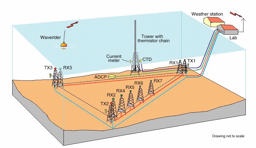
34 Experimental Arrangement Tutorial presented at Oceans 06 NURC 58 Experimental Arrangement Tutorial presented at Oceans 06 NURC 59 30
35 Experimental Arrangement Coastline Dominant direction of waves is from Tutorial presented at Oceans 06 NURC 60 Phase variation across receive array 0 secs 100 Data Tutorial presented at Oceans 06 NURC 61 31
36 Day σ in deg/m Tutorial presented at Oceans 06 NURC 62 Impact on SAS array gain Storm Tutorial presented at Oceans 06 NURC 63 32
37 Findings of environmental study Phase variation across the ~60 m aperture at a range of ~60m from the transmitter TX3 is approximately linear in both calm and rough seas The temporal coherence function for the phase gradient is an oscillatory function and is driven by the sea surface wave spectrum. Tutorial presented at Oceans 06 NURC 64 IV. Applications Rail-based experiments Tow-body experiments AUV experiments Tutorial presented at Oceans 06 NURC 65 33
38 Shadow blur Graphic courtesy of H. Groen (TNO) Transmit beam pattern l v Shadow Target Excessive viewing angle differences at the extremities of the array lead to shadow blur This leads to an lower limit on the SAS resolution given by CRR λl 2 β r where l is the shadow length at the centre of the array y x v v v Effect is minimized by increasing operating frequency. Tutorial presented at Oceans 06 NURC 66 SAS vs SSS images of a wreck Remus 600 HF Synthetic Aperture Sonar Remus 100 Side Scan Sonar Hugin 1000 Side Scan Sonar Tutorial presented at Oceans 06 NURC 67 34

39 Wideband HFSAS khz Rx: Lr=26.7 cm, N=32. Tx: 20 deg x 10 deg L SAS = 5 m CRR = 5 cm. Tutorial presented at Oceans 06 NURC 68 Wideband HFSAS khz Rx: Lr=26.7 cm, N=32. Tx: 20 deg x 10 deg L SAS = 5 m CRR = 5 cm. Tutorial presented at Oceans 06 NURC 69 35

40 Wideband HFSAS khz Rx: Lr=26.7 cm, N=32. Tx: 20 deg x 10 deg L SAS = 5 m CRR = 5 cm. Tutorial presented at Oceans 06 NURC 70 Wideband HFSAS khz Rx: Lr=26.7 cm, N=32. Tx: 20 deg x 10 deg L SAS = 5 m CRR = 5 cm. Tutorial presented at Oceans 06 NURC 71 36
41 Wideband HFSAS khz Rx: Lr=26.7 cm, N=32. Tx: 20 deg x 10 deg L SAS = 5 m CRR = 5 cm. Tutorial presented at Oceans 06 NURC 72 Wideband HFSAS khz Rx: Lr=26.7 cm, N=32. Tx: 20 deg x 10 deg L SAS = 5 m CRR = 5 cm. Tutorial presented at Oceans 06 NURC 73 37


42 Wideband HFSAS khz Rx: Lr=26.7 cm, N=32. Tx: 20 deg x 10 deg L SAS = 5 m CRR = 5 cm. Tutorial presented at Oceans 06 NURC 74 SAS image & coherence map Tutorial presented at Oceans 06 NURC 75 38


43 Bathymetric map Tutorial presented at Oceans 06 NURC 76 Multi-aspect SAS Combines benefits of strip-map, squinted & spotlight SAS. Individual SAS lengths are limited by onset of viewing angle differences of targets (echo & shadow blur) Multi-aspect SAS exploits this viewing angle diversity. The drawback is system complexity due to large number of receiver channels, large transmission power. Tutorial presented at Oceans 06 NURC 77 39

 Tutorial")


44 100kHz multi-aspect imaging Equa WW II wreck (La Spezia area) Tutorial presented at Oceans 06 NURC 78 At sea validation of DPCA Tutorial presented at Oceans 06 NURC 79 40

* * Editorial")

45 At sea validation of DPCA α=4.3, ρ eff = 50.4 db Tutorial presented at Oceans 06 NURC 80 Multi-Aspect Imaging II. Equa WW II wreck (La Spezia area)* * Editorial note: Original slide linked to a movie file, not available in this reprint. Tutorial presented at Oceans 06 NURC 81 41

 for endurance equipped with high")


46 AUV based Synthetic Aperture Systems AUVs are the future of commercial and military seafloor surveys AUVs are well suited to SAS: operate at low speeds (3-4 knots) for endurance equipped with high performance navigation good stability independent of sea state Major collaborative R&D program on-going at Saclantcen which includes AUV-based SAS Ocean Explorer AUV Tutorial presented at Oceans 06 NURC 82 Examples of Synthetic Aperture Sonar and Side Scan Sonar 20 m 20 m 25 m Remus-600 HF SAS 25 m Remus-600 LF SAS 70 m Hugin EdgeTech 4400 SAS 65 m Remus-100 MS 900kHz SSS Tutorial presented at Oceans 06 NURC 83 42
 and lightweight (400 kg) 21 vehicle (Bluefin) High accuracy (<5 m/hr) IXSEA PHINS aided inertial navigation system Real-team multi-beam SSS (13 beams spaced at 4 cm) Programmable transmission")

47 MUSCLE Compact (3.5 m) and lightweight (400 kg) 21 vehicle (Bluefin) High accuracy (<5 m/hr) IXSEA PHINS aided inertial navigation system Real-team multi-beam SSS (13 beams spaced at 4 cm) Programmable transmission with down to 2 deg beam width Long range and short range transmissions in two sub-bands Receive elements with selectable vertical beampatterns Plan to implement on-board SAS processing up to 2.5 cm at 225m USBL/LBL TRACKING FIN ANTENNA WI-LAN GPS RDF BEACON RECEIVER ARRAY TRANSMITTER ARRAY GIMBAL DUCTED THRUSTER JUNCTION BOX INTERFEROMETRIC RECEIVER ARRAY Tutorial presented at Oceans 06 NURC 84 NATO SONAR DESIGN 120 cm 5 cm 12 cm 3.3 cm Rx Tx Long-range: Red frequency ( khz), Narrow-beam Tx/Rx with 4 deg depression Short range: Blue frequency ( khz), Wide-beam Tx/ Rx with 8 deg depression Multipath is rejected by a combination of spatial & temporal filtering 14 deg 28 deg 10 deg 21 deg Tutorial presented at Oceans 06 NURC 85 43
48 ESPRESSO PERFORMANCE PREDICTION Blue line: Short range sonar Red line: Long range sonar Black line: conventional sonar (for comparison) Water depth 20 m Sonar altitude 15 m Range: 1.5 to 10 x water depth Tutorial presented at Oceans 06 NURC 86 Tutorial presented at Oceans 06 NURC 87 44
49 Tutorial presented at Oceans 06 NURC 88 Tutorial presented at Oceans 06 NURC 89 45

50 Tutorial presented at Oceans 06 NURC 90 Tutorial presented at Oceans 06 NURC 91 46
51 1 m 1 m Tutorial presented at Oceans 06 NURC 92 1 m 1 m Tutorial presented at Oceans 06 NURC 93 47
52 Document Data Sheet Security Classification RELEASABLE TO THE PUBLIC Project No. Document Serial No. NURC-PR Author(s) Pinto, Marc Date of Issue October 2006 Total Pages 52pp. Title Design of synthetic aperture sonar systems for high-resolution seabed imaging (tutorial slides) Abstract. Keywords Issuing Organization NATO Undersea Research Centre Viale San Bartolomeo 400, La Spezia, Italy [From N. America: NATO Undersea Research Centre (New York) APO AE ] Tel: Fax:
Experimental results of a 300 khz shallow water synthetic aperture sonar
 Reprint Series Experimental results of a 300 khz shallow water synthetic aperture sonar Andrea Bellettini, Marc Pinto, Benjamin Evans November 2007 Originally published in: Proceedings of the 2 nd International
Performance assessment of the MUSCLE synthetic aperture sonar
 SCIENCE AND TECHNOLOGY ORGANIZATION CENTRE FOR MARITIME RESEARCH AND EXPERIMENTATION Reprint Series Performance assessment of the MUSCLE synthetic aperture sonar Michel Couillard, Johannes Groen, Warren
MULTIPATH EFFECT ON DPCA MICRONAVIGATION OF A SYNTHETIC APERTURE SONAR
 MULTIPATH EFFECT ON DPCA MICRONAVIGATION OF A SYNTHETIC APERTURE SONAR L. WANG, G. DAVIES, A. BELLETTINI AND M. PINTO SACLANT Undersea Research Centre, Viale San Bartolomeo 400, 19138 La Spezia, Italy
Shallow water synthetic aperture sonar: an enabling technology for NATO MCM forces
 Reprint Series Shallow water synthetic aperture sonar: an enabling technology for NATO MCM forces Marc Pinto, Andrea Bellettini October 2007 Originally published in: UDT Europe, Undersea Defence Technology
Multipass coherent processing on synthetic aperture sonar data
 Multipass coherent processing on synthetic aperture sonar data Stig A V Synnes, Hayden J Callow, Roy E Hansen, Torstein O Sæbø Norwegian Defence Research Establishment (FFI), P O Box 25, NO-2027 Kjeller,
SYSTEM 5900 SIDE SCAN SONAR
 SYSTEM 5900 SIDE SCAN SONAR HIGH-RESOLUTION, DYNAMICALLY FOCUSED, MULTI-BEAM SIDE SCAN SONAR Klein Marine System s 5900 sonar is the flagship in our exclusive family of multi-beam technology-based side
Underwater source localization using a hydrophone-equipped glider
 SCIENCE AND TECHNOLOGY ORGANIZATION CENTRE FOR MARITIME RESEARCH AND EXPERIMENTATION Reprint Series Underwater source localization using a hydrophone-equipped glider Jiang, Y.M., Osler, J. January 2014
HIGH RESOLUTION MULTI-BEAM SIDE LOOKING SONAR ANDRZEJ ELMINOWICZ, LEONARD ZAJĄCZKOWSKI
 HIGH RESOLUTION MULTI-BEAM SIDE LOOKING SONAR ANDRZEJ ELMINOWICZ, LEONARD ZAJĄCZKOWSKI R&D Marine Technology Centre Dickmana 62, 81-109 Gdynia, POLAND email: andrzeje@ctm.gdynia.pl The conventional side
The Potential of Synthetic Aperture Sonar in seafloor imaging
 The Potential of Synthetic Aperture Sonar in seafloor imaging CM 2000/T:12 Ron McHugh Heriot-Watt University, Department of Computing and Electrical Engineering, Edinburgh, EH14 4AS, Scotland, U.K. Tel:
Phased Array Velocity Sensor Operational Advantages and Data Analysis
 Phased Array Velocity Sensor Operational Advantages and Data Analysis Matt Burdyny, Omer Poroy and Dr. Peter Spain Abstract - In recent years the underwater navigation industry has expanded into more diverse
Three-dimensional investigation of buried structures with multi-transducer parametric sub-bottom profiler as part of hydrographical applications
 Three-dimensional investigation of buried structures with multi-transducer parametric sub-bottom profiler as part Jens LOWAG, Germany, Dr. Jens WUNDERLICH, Germany, Peter HUEMBS, Germany Key words: parametric,
Principles of Pulse-Doppler Radar p. 1 Types of Doppler Radar p. 1 Definitions p. 5 Doppler Shift p. 5 Translation to Zero Intermediate Frequency p.
 Preface p. xv Principles of Pulse-Doppler Radar p. 1 Types of Doppler Radar p. 1 Definitions p. 5 Doppler Shift p. 5 Translation to Zero Intermediate Frequency p. 6 Doppler Ambiguities and Blind Speeds
Broadband Temporal Coherence Results From the June 2003 Panama City Coherence Experiments
 Broadband Temporal Coherence Results From the June 2003 Panama City Coherence Experiments H. Chandler*, E. Kennedy*, R. Meredith*, R. Goodman**, S. Stanic* *Code 7184, Naval Research Laboratory Stennis
Ongoing Developments in Side Scan Sonar The pursuit of better Range, Resolution and Speed
 Ongoing Developments in Side Scan Sonar The pursuit of better Range, Resolution and Speed Nick Lawrence EdgeTech Advances in Seafloor-mapping Sonar Conference 30 th November 2009 Company Profile EdgeTech
Space-Time Adaptive Processing Using Sparse Arrays
 Space-Time Adaptive Processing Using Sparse Arrays Michael Zatman 11 th Annual ASAP Workshop March 11 th -14 th 2003 This work was sponsored by the DARPA under Air Force Contract F19628-00-C-0002. Opinions,
SUB-SEABED MAPPING USING AUV-BASED MULTI-STATIC ACOUSTIC SENSING AND ADAPTIVE CONTROL
 SUB-SEABED MAPPING USING AUV-BASED MULTI-STATIC ACOUSTIC SENSING AND ADAPTIVE CONTROL H. SCHMIDT, J. LEONARD, J.R. EDWARDS AND T-C. LIU Massachusetts Institute of Technology, 77 Massachusetts Avenue, Cambridge
A Hybrid Indoor Tracking System for First Responders
 A Hybrid Indoor Tracking System for First Responders Precision Indoor Personnel Location and Tracking for Emergency Responders Technology Workshop August 4, 2009 Marc Harlacher Director, Location Solutions
MULTI-CHANNEL SAR EXPERIMENTS FROM THE SPACE AND FROM GROUND: POTENTIAL EVOLUTION OF PRESENT GENERATION SPACEBORNE SAR
 3 nd International Workshop on Science and Applications of SAR Polarimetry and Polarimetric Interferometry POLinSAR 2007 January 25, 2007 ESA/ESRIN Frascati, Italy MULTI-CHANNEL SAR EXPERIMENTS FROM THE
Tritech International Vehicle Sonar Developments
 Tritech International Vehicle Sonar Developments Mike Broadbent Business Development Manager Oceanology 2012 - UUVS Overview About Tritech Mechanical Scanning Sonar - Improving the performance High Speed
ECE 476/ECE 501C/CS Wireless Communication Systems Winter Lecture 6: Fading
 ECE 476/ECE 501C/CS 513 - Wireless Communication Systems Winter 2003 Lecture 6: Fading Last lecture: Large scale propagation properties of wireless systems - slowly varying properties that depend primarily
ECE 476/ECE 501C/CS Wireless Communication Systems Winter Lecture 6: Fading
 ECE 476/ECE 501C/CS 513 - Wireless Communication Systems Winter 2004 Lecture 6: Fading Last lecture: Large scale propagation properties of wireless systems - slowly varying properties that depend primarily
ECE 476/ECE 501C/CS Wireless Communication Systems Winter Lecture 6: Fading
 ECE 476/ECE 501C/CS 513 - Wireless Communication Systems Winter 2005 Lecture 6: Fading Last lecture: Large scale propagation properties of wireless systems - slowly varying properties that depend primarily
ESA Radar Remote Sensing Course ESA Radar Remote Sensing Course Radar, SAR, InSAR; a first introduction
 Radar, SAR, InSAR; a first introduction Ramon Hanssen Delft University of Technology The Netherlands r.f.hanssen@tudelft.nl Charles University in Prague Contents Radar background and fundamentals Imaging
PHINS, An All-In-One Sensor for DP Applications
 DYNAMIC POSITIONING CONFERENCE September 28-30, 2004 Sensors PHINS, An All-In-One Sensor for DP Applications Yves PATUREL IXSea (Marly le Roi, France) ABSTRACT DP positioning sensors are mainly GPS receivers
Wireless Channel Propagation Model Small-scale Fading
 Wireless Channel Propagation Model Small-scale Fading Basic Questions T x What will happen if the transmitter - changes transmit power? - changes frequency? - operates at higher speed? Transmit power,
Synthetic Aperture Radar
 Synthetic Aperture Radar Picture 1: Radar silhouette of a ship, produced with the ISAR-Processor of the Ocean Master A Synthetic Aperture Radar (SAR), or SAR, is a coherent mostly airborne or spaceborne
Chapter 4 DOA Estimation Using Adaptive Array Antenna in the 2-GHz Band
 Chapter 4 DOA Estimation Using Adaptive Array Antenna in the 2-GHz Band 4.1. Introduction The demands for wireless mobile communication are increasing rapidly, and they have become an indispensable part
Applications of iusbl Technology overview
 Applications of iusbl Technology overview Tom Bennetts Project Manager Summary 1. What is iusbl and its target applications 2. Advantages of iusbl and sample data 3. Technical hurdles and Calibration methods
EENG473 Mobile Communications Module 3 : Week # (12) Mobile Radio Propagation: Small-Scale Path Loss
 Mobile Radio Propagation: Small-Scale Path Loss") EENG473 Mobile Communications Module 3 : Week # (12) Mobile Radio Propagation: Small-Scale Path Loss Introduction Small-scale fading is used to describe the rapid fluctuation of the amplitude of a radio
EENG473 Mobile Communications Module 3 : Week # (12) Mobile Radio Propagation: Small-Scale Path Loss Introduction Small-scale fading is used to describe the rapid fluctuation of the amplitude of a radio
A Stepped Frequency CW SAR for Lightweight UAV Operation
 UNCLASSIFIED/UNLIMITED A Stepped Frequency CW SAR for Lightweight UAV Operation ABSTRACT Dr Keith Morrison Department of Aerospace, Power and Sensors University of Cranfield, Shrivenham Swindon, SN6 8LA
Side-Scan Sonar Presentation STS
 Training Module Side-Scan Sonar Presentation STS SIDE-SCAN SONAR SAFETY Training Module Content: This module includes information on: Types of Side-Scan Benefits and Disadvantages System Configuration
Exploitation of Environmental Complexity in Shallow Water Acoustic Data Communications
 Exploitation of Environmental Complexity in Shallow Water Acoustic Data Communications W.S. Hodgkiss Marine Physical Laboratory Scripps Institution of Oceanography La Jolla, CA 92093-0701 phone: (858)
Acknowledgment. Process of Atmospheric Radiation. Atmospheric Transmittance. Microwaves used by Radar GMAT Principles of Remote Sensing
 GMAT 9600 Principles of Remote Sensing Week 4 Radar Background & Surface Interactions Acknowledgment Mike Chang Natural Resources Canada Process of Atmospheric Radiation Dr. Linlin Ge and Prof Bruce Forster
High-Frequency Rapid Geo-acoustic Characterization
 High-Frequency Rapid Geo-acoustic Characterization Kevin D. Heaney Lockheed-Martin ORINCON Corporation, 4350 N. Fairfax Dr., Arlington VA 22203 Abstract. The Rapid Geo-acoustic Characterization (RGC) algorithm
Mobile Radio Propagation: Small-Scale Fading and Multi-path
 Mobile Radio Propagation: Small-Scale Fading and Multi-path 1 EE/TE 4365, UT Dallas 2 Small-scale Fading Small-scale fading, or simply fading describes the rapid fluctuation of the amplitude of a radio
Mobile Radio Propagation Channel Models
 Wireless Information Transmission System Lab. Mobile Radio Propagation Channel Models Institute of Communications Engineering National Sun Yat-sen University Table of Contents Introduction Propagation
Ultrasound Beamforming and Image Formation. Jeremy J. Dahl
 Ultrasound Beamforming and Image Formation Jeremy J. Dahl Overview Ultrasound Concepts Beamforming Image Formation Absorption and TGC Advanced Beamforming Techniques Synthetic Receive Aperture Parallel
Company Profile. Facilities
 Company Profile R2Sonic was founded in February 2006 by three veteran underwater acoustical engineers; Jens R. Steenstrup, Mark Chun and Kirk Hobart; with the mission to utilize their experience to bring
Results from a Small Synthetic Aperture Sonar
 Results from a Small Synthetic Aperture Sonar Daniel Brown, Daniel Cook, Jose Fernandez Naval Surface Warfare Center - Panama City Code HS11 11 Vernon Avenue Panama City, FL 3247-71 Abstract A Synthetic
THE NASA/JPL AIRBORNE SYNTHETIC APERTURE RADAR SYSTEM. Yunling Lou, Yunjin Kim, and Jakob van Zyl
 THE NASA/JPL AIRBORNE SYNTHETIC APERTURE RADAR SYSTEM Yunling Lou, Yunjin Kim, and Jakob van Zyl Jet Propulsion Laboratory California Institute of Technology 4800 Oak Grove Drive, MS 300-243 Pasadena,
KONGSBERG seafloor-mapping echosounders
 KONGSBERG seafloor-mapping echosounders Berit Horvei WORLD CLASS through people, technology and dedication AGENDA Historical overview EM series Multibeam echosounder and Subbottom profiler Topside software.
Radar Systems Engineering Lecture 14 Airborne Pulse Doppler Radar
 Radar Systems Engineering Lecture 14 Airborne Pulse Doppler Radar Dr. Robert M. O Donnell Guest Lecturer Radar Systems Course 1 Examples of Airborne Radars F-16 APG-66, 68 Courtesy of US Navy Courtesy
inter.noise 2000 The 29th International Congress and Exhibition on Noise Control Engineering August 2000, Nice, FRANCE
 Copyright SFA - InterNoise 2000 1 inter.noise 2000 The 29th International Congress and Exhibition on Noise Control Engineering 27-30 August 2000, Nice, FRANCE I-INCE Classification: 7.2 MICROPHONE ARRAY
THE UTILITY OF SYNTHETIC APERTURE SONAR IN SEAFLOOR IMAGING MARCIN SZCZEGIELNIAK
 THE UTILITY OF SYNTHETIC APERTURE SONAR IN SEAFLOOR IMAGING MARCIN SZCZEGIELNIAK University of Technology and Agriculture in Bydgoszcz 7 Kalisky Ave, 85-79 Bydgoszcz, Poland e-mail: marcinszczegielniak@poczta.onet.pl
Ocean Ambient Noise Studies for Shallow and Deep Water Environments
 DISTRIBUTION STATEMENT A. Approved for public release; distribution is unlimited. Ocean Ambient Noise Studies for Shallow and Deep Water Environments Martin Siderius Portland State University Electrical
CEGEG046 / GEOG3051 Principles & Practice of Remote Sensing (PPRS) 8: RADAR 1
 8: RADAR 1") CEGEG046 / GEOG3051 Principles & Practice of Remote Sensing (PPRS) 8: RADAR 1 Dr. Mathias (Mat) Disney UCL Geography Office: 113, Pearson Building Tel: 7670 05921 Email: mdisney@ucl.geog.ac.uk www.geog.ucl.ac.uk/~mdisney
CEGEG046 / GEOG3051 Principles & Practice of Remote Sensing (PPRS) 8: RADAR 1 Dr. Mathias (Mat) Disney UCL Geography Office: 113, Pearson Building Tel: 7670 05921 Email: mdisney@ucl.geog.ac.uk www.geog.ucl.ac.uk/~mdisney
Mid-Frequency Reverberation Measurements with Full Companion Environmental Support
 DISTRIBUTION STATEMENT A. Approved for public release; distribution is unlimited. Mid-Frequency Reverberation Measurements with Full Companion Environmental Support Dajun (DJ) Tang Applied Physics Laboratory,
Test Results from a Multi-Frequency Bathymetric Synthetic Aperture Sonar
 Test Results from a Multi-Frequency Bathymetric Synthetic Aperture Sonar M. P. Hayes, P. J. Barclay, P. T. Gough, and H. J. Callow Acoustics Research Group Department of Electrical and Electronic Engineering,
Multistatic, Concurrent Detection, Classification and Localization Concepts for Autonomous, Shallow Water Mine Counter Measures
 Multistatic, Concurrent Detection, Classification and Localization Concepts for Autonomous, Shallow Water Mine Counter Measures PI: Henrik Schmidt Massachusetts Institute of Technology 77 Massachusetts
MINE SEARCH MISSION PLANNING FOR HIGH DEFINITION SONAR SYSTEM - SELECTION OF SPACE IMAGING EQUIPMENT FOR A SMALL AUV DOROTA ŁUKASZEWICZ, LECH ROWIŃSKI
 MINE SEARCH MISSION PLANNING FOR HIGH DEFINITION SONAR SYSTEM - SELECTION OF SPACE IMAGING EQUIPMENT FOR A SMALL AUV DOROTA ŁUKASZEWICZ, LECH ROWIŃSKI Gdansk University of Technology Faculty of Ocean Engineering
Multiple Antenna Processing for WiMAX
 Multiple Antenna Processing for WiMAX Overview Wireless operators face a myriad of obstacles, but fundamental to the performance of any system are the propagation characteristics that restrict delivery
Rec. ITU-R F RECOMMENDATION ITU-R F *
 Rec. ITU-R F.162-3 1 RECOMMENDATION ITU-R F.162-3 * Rec. ITU-R F.162-3 USE OF DIRECTIONAL TRANSMITTING ANTENNAS IN THE FIXED SERVICE OPERATING IN BANDS BELOW ABOUT 30 MHz (Question 150/9) (1953-1956-1966-1970-1992)
Space-Time Adaptive Processing: Fundamentals
 Wolfram Bürger Research Institute for igh-frequency Physics and Radar Techniques (FR) Research Establishment for Applied Science (FGAN) Neuenahrer Str. 2, D-53343 Wachtberg GERMANY buerger@fgan.de ABSTRACT
Shallow Water Fluctuations and Communications
 Shallow Water Fluctuations and Communications H.C. Song Marine Physical Laboratory Scripps Institution of oceanography La Jolla, CA 92093-0238 phone: (858) 534-0954 fax: (858) 534-7641 email: hcsong@mpl.ucsd.edu
Rec. ITU-R P RECOMMENDATION ITU-R P *
 Rec. ITU-R P.682-1 1 RECOMMENDATION ITU-R P.682-1 * PROPAGATION DATA REQUIRED FOR THE DESIGN OF EARTH-SPACE AERONAUTICAL MOBILE TELECOMMUNICATION SYSTEMS (Question ITU-R 207/3) Rec. 682-1 (1990-1992) The
CHAPTER 2 WIRELESS CHANNEL
 CHAPTER 2 WIRELESS CHANNEL 2.1 INTRODUCTION In mobile radio channel there is certain fundamental limitation on the performance of wireless communication system. There are many obstructions between transmitter
Smart antenna technology
 Smart antenna technology In mobile communication systems, capacity and performance are usually limited by two major impairments. They are multipath and co-channel interference [5]. Multipath is a condition
Electronically Steerable planer Phased Array Antenna
 Electronically Steerable planer Phased Array Antenna Amandeep Kaur Department of Electronics and Communication Technology, Guru Nanak Dev University, Amritsar, India Abstract- A planar phased-array antenna
Design of an Airborne SLAR Antenna at X-Band
 Design of an Airborne SLAR Antenna at X-Band Markus Limbach German Aerospace Center (DLR) Microwaves and Radar Institute Oberpfaffenhofen WFMN 2007, Markus Limbach, Folie 1 Overview Applications of SLAR
Effects of snaking for a towed sonar array on an AUV
 Lorentzen, Ole J., Effects of snaking for a towed sonar array on an AUV, Proceedings of the 38 th Scandinavian Symposium on Physical Acoustics, Geilo February 1-4, 2015. Editor: Rolf J. Korneliussen, ISBN
Small-Scale Fading I PROF. MICHAEL TSAI 2011/10/27
 Small-Scale Fading I PROF. MICHAEL TSAI 011/10/7 Multipath Propagation RX just sums up all Multi Path Component (MPC). Multipath Channel Impulse Response An example of the time-varying discrete-time impulse
Narrow- and wideband channels
 RADIO SYSTEMS ETIN15 Lecture no: 3 Narrow- and wideband channels Ove Edfors, Department of Electrical and Information technology Ove.Edfors@eit.lth.se 2012-03-19 Ove Edfors - ETIN15 1 Contents Short review
TEST RESULTS OF A DIGITAL BEAMFORMING GPS RECEIVER FOR MOBILE APPLICATIONS
 TEST RESULTS OF A DIGITAL BEAMFORMING GPS RECEIVER FOR MOBILE APPLICATIONS Alison Brown, Huan-Wan Tseng, and Randy Kurtz, NAVSYS Corporation BIOGRAPHY Alison Brown is the President and CEO of NAVSYS Corp.
Teledyne Marine Acoustic Imagining
 RESON SeaBat high performance sonars for long range object detection and MCM applications Navigation, object avoidance & up close inspection with BlueView Greg Probst Sales Manager, Defense Teledyne Marine
ADAPTIVE ANTENNAS. TYPES OF BEAMFORMING
 ADAPTIVE ANTENNAS TYPES OF BEAMFORMING 1 1- Outlines This chapter will introduce : Essential terminologies for beamforming; BF Demonstrating the function of the complex weights and how the phase and amplitude
Microwave Remote Sensing (1)
") Microwave Remote Sensing (1) Microwave sensing encompasses both active and passive forms of remote sensing. The microwave portion of the spectrum covers the range from approximately 1cm to 1m in wavelength.
Microwave Remote Sensing (1) Microwave sensing encompasses both active and passive forms of remote sensing. The microwave portion of the spectrum covers the range from approximately 1cm to 1m in wavelength.
Radar Systems Engineering Lecture 15 Parameter Estimation And Tracking Part 1
 Radar Systems Engineering Lecture 15 Parameter Estimation And Tracking Part 1 Dr. Robert M. O Donnell Guest Lecturer Radar Systems Course 1 Block Diagram of Radar System Transmitter Propagation Medium
Null-steering GPS dual-polarised antenna arrays
 Presented at SatNav 2003 The 6 th International Symposium on Satellite Navigation Technology Including Mobile Positioning & Location Services Melbourne, Australia 22 25 July 2003 Null-steering GPS dual-polarised
Antennas and Propagation. Chapter 5c: Array Signal Processing and Parametric Estimation Techniques
 Antennas and Propagation : Array Signal Processing and Parametric Estimation Techniques Introduction Time-domain Signal Processing Fourier spectral analysis Identify important frequency-content of signal
Principles of Space- Time Adaptive Processing 3rd Edition. By Richard Klemm. The Institution of Engineering and Technology
 Principles of Space- Time Adaptive Processing 3rd Edition By Richard Klemm The Institution of Engineering and Technology Contents Biography Preface to the first edition Preface to the second edition Preface
A Bistatic HF Radar for Current Mapping and Robust Ship Tracking
 A Bistatic HF Radar for Current Mapping and Robust Ship Tracking D. B. Trizna Imaging Science Research, Inc. 6103B Virgo Court Burke, VA, 22015 USA Abstract- A bistatic HF radar has been developed for
ON WAVEFORM SELECTION IN A TIME VARYING SONAR ENVIRONMENT
 ON WAVEFORM SELECTION IN A TIME VARYING SONAR ENVIRONMENT Ashley I. Larsson 1* and Chris Gillard 1 (1) Maritime Operations Division, Defence Science and Technology Organisation, Edinburgh, Australia Abstract
Introduction Active microwave Radar
 RADAR Imaging Introduction 2 Introduction Active microwave Radar Passive remote sensing systems record electromagnetic energy that was reflected or emitted from the surface of the Earth. There are also
Basic Radar Definitions Introduction p. 1 Basic relations p. 1 The radar equation p. 4 Transmitter power p. 9 Other forms of radar equation p.
 Basic Radar Definitions Basic relations p. 1 The radar equation p. 4 Transmitter power p. 9 Other forms of radar equation p. 11 Decibel representation of the radar equation p. 13 Radar frequencies p. 15
global acoustic positioning system GAPS usbl acoustic with integrated INS positioning system Ixsea Oceano GAPS page 1
 global acoustic positioning system usbl acoustic positioning system with integrated INS positioning system page 1 THE MERGER OF INERTIAL AND UNDERWATER ACOUSTIC TECHNOLOGIES is a unique Global Acoustic
Fringe Parameter Estimation and Fringe Tracking. Mark Colavita 7/8/2003
 Fringe Parameter Estimation and Fringe Tracking Mark Colavita 7/8/2003 Outline Visibility Fringe parameter estimation via fringe scanning Phase estimation & SNR Visibility estimation & SNR Incoherent and
Challenges in Advanced Moving-Target Processing in Wide-Band Radar
 Challenges in Advanced Moving-Target Processing in Wide-Band Radar July 9, 2012 Douglas Page, Gregory Owirka, Howard Nichols 1 1 BAE Systems 6 New England Executive Park Burlington, MA 01803 Steven Scarborough,
A Bistatic HF Radar for Current Mapping and Robust Ship Tracking
 A Bistatic HF Radar for Current Mapping and Robust Ship Tracking Dennis Trizna Imaging Science Research, Inc. V. 703-801-1417 dennis @ isr-sensing.com www.isr-sensing.com Objective: Develop methods for
Know how Pulsed Doppler radar works and how it s able to determine target velocity. Know how the Moving Target Indicator (MTI) determines target
 determines target") Moving Target Indicator 1 Objectives Know how Pulsed Doppler radar works and how it s able to determine target velocity. Know how the Moving Target Indicator (MTI) determines target velocity. Be able to
Moving Target Indicator 1 Objectives Know how Pulsed Doppler radar works and how it s able to determine target velocity. Know how the Moving Target Indicator (MTI) determines target velocity. Be able to
Shallow Water MCM using Off-Board, Autonomous Sensor Networks and Multistatic, Time-Reversal Acoustics
 Shallow Water MCM using Off-Board, Autonomous Sensor Networks and Multistatic, Time-Reversal Acoustics William A. Kuperman, Karim Sabra, Philippe Roux and William S. Hodgkiss Marine Physics Laboratory
Sonar advancements for coastal and maritime surveys
 ConférenceMéditerranéenneCôtièreetMaritime EDITION1,HAMMAMET,TUNISIE(2009) CoastalandMaritimeMediterraneanConference Disponibleenligne http://www.paralia.fr Availableonline Sonar advancements for coastal
Positioning Small AUVs for Deeper Water Surveys Using Inverted USBL
 Positioning Small AUVs for Deeper Water Surveys Using Inverted USBL Presented at Hydro12, Rotterdam, November 2012 Dr. T.M. Hiller, thiller@teledyne.com Overview Introduction to Gavia AUV Gavia Acoustic
USBL positioning and communication systems. Applications
 USBL positioning and communication systems Offering a powerful USBL transceiver functionality with full benefits of an S2C technology communication link Applications Positioning of offshore equipment >
Effects of Fading Channels on OFDM
 IOSR Journal of Engineering (IOSRJEN) e-issn: 2250-3021, p-issn: 2278-8719, Volume 2, Issue 9 (September 2012), PP 116-121 Effects of Fading Channels on OFDM Ahmed Alshammari, Saleh Albdran, and Dr. Mohammad
Bistatic Synthetic Aperture Target Detection and Imaging With an AUV
 690 IEEE JOURNAL OF OCEANIC ENGINEERING, VOL. 26, NO. 4, OCTOBER 2001 Bistatic Synthetic Aperture Target Detection and Imaging With an AUV Joseph R. Edwards, Henrik Schmidt, and Kevin D. LePage Abstract
Exploitation of frequency information in Continuous Active Sonar
 PROCEEDINGS of the 22 nd International Congress on Acoustics Underwater Acoustics : ICA2016-446 Exploitation of frequency information in Continuous Active Sonar Lisa Zurk (a), Daniel Rouseff (b), Scott
Advanced Antenna Technology
 Advanced Antenna Technology Abdus Salam ICTP, February 2004 School on Digital Radio Communications for Research and Training in Developing Countries Ermanno Pietrosemoli Latin American Networking School
High Frequency Acoustic Channel Characterization for Propagation and Ambient Noise
 High Frequency Acoustic Channel Characterization for Propagation and Ambient Noise Martin Siderius Portland State University, ECE Department 1900 SW 4 th Ave., Portland, OR 97201 phone: (503) 725-3223
WIRELESS COMMUNICATION TECHNOLOGIES (16:332:546) LECTURE 5 SMALL SCALE FADING
 LECTURE 5 SMALL SCALE FADING") WIRELESS COMMUNICATION TECHNOLOGIES (16:332:546) LECTURE 5 SMALL SCALE FADING Instructor: Dr. Narayan Mandayam Slides: SabarishVivek Sarathy A QUICK RECAP Why is there poor signal reception in urban clutters?
WIRELESS COMMUNICATION TECHNOLOGIES (16:332:546) LECTURE 5 SMALL SCALE FADING Instructor: Dr. Narayan Mandayam Slides: SabarishVivek Sarathy A QUICK RECAP Why is there poor signal reception in urban clutters?
Optimizing Resolution and Uncertainty in Bathymetric Sonar Systems
 University of New Hampshire University of New Hampshire Scholars' Repository Center for Coastal and Ocean Mapping Center for Coastal and Ocean Mapping 6-2013 Optimizing Resolution and Uncertainty in Bathymetric
Antenna Design and Site Planning Considerations for MIMO
 Antenna Design and Site Planning Considerations for MIMO Steve Ellingson Mobile & Portable Radio Research Group (MPRG) Dept. of Electrical & Computer Engineering Virginia Polytechnic Institute & State
Antennas and Propagation. Chapter 6a: Propagation Definitions, Path-based Modeling
 Antennas and Propagation a: Propagation Definitions, Path-based Modeling Introduction Propagation How signals from antennas interact with environment Goal: model channel connecting TX and RX Antennas and
Integrated Detection and Tracking in Multistatic Sonar
 Stefano Coraluppi Reconnaissance, Surveillance, and Networks Department NATO Undersea Research Centre Viale San Bartolomeo 400 19138 La Spezia ITALY coraluppi@nurc.nato.int ABSTRACT An ongoing research
NETW 701: Wireless Communications. Lecture 5. Small Scale Fading
 NETW 701: Wireless Communications Lecture 5 Small Scale Fading Small Scale Fading Most mobile communication systems are used in and around center of population. The transmitting antenna or Base Station
SWAMSI: Bistatic CSAS and Target Echo Studies
 SWAMSI: Bistatic CSAS and Target Echo Studies Kent Scarbrough Advanced Technology Laboratory Applied Research Laboratories The University of Texas at Austin P.O. Box 8029 Austin, TX 78713-8029 phone: (512)
CHAPTER 10 CONCLUSIONS AND FUTURE WORK 10.1 Conclusions
 CHAPTER 10 CONCLUSIONS AND FUTURE WORK 10.1 Conclusions This dissertation reported results of an investigation into the performance of antenna arrays that can be mounted on handheld radios. Handheld arrays
Design and Performance Simulation of a Ku-Band Rotating Fan-Beam Scatterometer
 Design and Performance Simulation of a Ku-Band Rotating Fan-Beam Scatterometer Xiaolong DONG, Wenming LIN, Di ZHU, (CSSAR/CAS) PO Box 8701, Beijing, 100190, China Tel: +86-10-62582841, Fax: +86-10-62528127
Mathematical Modeling of Ultrasonic Phased Array for Obstacle Location for Visually Impaired
 IOSR Journal of VLSI and Signal Processing (IOSR-JVSP) Volume 2, Issue 6 (Jul. Aug. 2013), PP 52-56 e-issn: 2319 4200, p-issn No. : 2319 4197 Mathematical Modeling of Ultrasonic Phased Array for Obstacle
Time Reversal Ocean Acoustic Experiments At 3.5 khz: Applications To Active Sonar And Undersea Communications
 Time Reversal Ocean Acoustic Experiments At 3.5 khz: Applications To Active Sonar And Undersea Communications Heechun Song, P. Roux, T. Akal, G. Edelmann, W. Higley, W.S. Hodgkiss, W.A. Kuperman, K. Raghukumar,
Interference Mitigation Using a Multiple Feed Array for Radio Astronomy
 Interference Mitigation Using a Multiple Feed Array for Radio Astronomy Chad Hansen, Karl F Warnick, and Brian D Jeffs Department of Electrical and Computer Engineering Brigham Young University Provo,