MX170C NAV-COMM OWNER'S MANUAL
|
|
|
- Abigayle Dawson
- 5 years ago
- Views:
Transcription

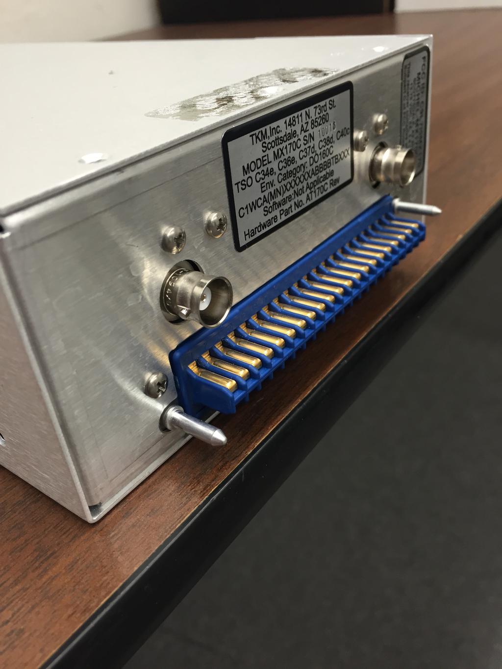
1 1 MX170C NAV-COMM OWNER'S MANUAL TK M, INC NORTH 73 rd STREET SCO TTSDALE, AZ PART# MN0170C, REV. 1 NOV 17,2008
2 2 I. INTRODUCTION This manual contains information on the TKM MX170(C), manufactured by TKM, Inc. The information includes installation, operation, mechanical and electrical descriptions and alignment and test considerations. The MX170(C) is authorized by the Federal Aviation Administration to TSO C34e, C36e, C37d, C38d, C40c, and has met the test requirements of RTCAlDO-160C. A. Purpose of Equipment The equipment is a 760 channel communication (COMM) transceiver for use in aviation services and a 200 channel navigation (NAV) receiver to provide VOR / LOC signals to navigational converters. The NAV receiver also provides frequency selection for remote mounted Distance Measuring Equipment and Glide slope Receivers. The MX170(C) is designed to be a direct replacement for the King KX170/ KX175. The unit is dimensionally identical to the King units and can therefore use existing aircraft installations. Except for improved performance characteristics, the unit is electrically interchangeable with the King units and will provide the proper audio, navigation and channeling signals for existing installations. New installations can be made using KX170A installation kits. B. Equipment Description The unit features digital (LED) displays for active (yellow) frequency channel and standby (red) frequency channel for both COMM and NAV. For channel selection a MHz knob and a KHz knob are provided. For 25 KHz increments in COMM, a 25 KHz button is provided. To activate COMM or NAV frequency selection, an N -C button is provided, a tic appears in the selected standby channel display. Channel selection operates on the standby channel only. When the desired channel is indicated in the standby display, it may be placed into the active position by depressing the 'Flip-flop' button located left of the displays. The active channel is then placed into the standby position. The NAV receiver features a VC-ID button to permit selection of voice or ident reception. In the Ident condition a 'tic' is displayed on the active NAV channel display. The COMM transceiver features a test button that overrides the squelch to verify proper receiver operation and to allow reception of weak signals. Also provided on the active COMM display is a 'tic' to indicate transmitter power output. Power switches are incorporated with the NAV and COMM volume controls. The COMM is the master power switch and the NAV provides power switching for remote navigation units.
3 3 The MX170(C) is comprised of eight replaceable subassemblies. Five of the subassemblies are contained in shielded modules in order to reduce radio frequency interference. The five are the NA V receiver, the NA V synthesizer, the COMM receiver, the COMM synthesizer, and the Transmitter. The remaining three subassemblies are the Rear Panel Assembly, the Front Panel Assembly and the Computer Board. The Rear Panel Assembly contains the Audio Amplifier, Power Filter, and the T/R switching. The Front Panel Assembly contains the digital displays, the function select switches and the volume controls. The Computer Board contains the microprocessor, the memory, and program storage. Also contained on the computer board are the audio processing circuits and the channeling circuits. The subassemblies are interconnected with plugs so that any module may be replaced without the use of a soldering iron. For equipment repair it is recommended that complete subassemblies be replaced. As an aid to locating the defective subassembly a set of analog test points are provided. The analog test points include the receiver tuning voltages, synthesizer control voltages, and the AGC lines. C. Specifications MXI70(C) TRANSCEIVER Mounting: Size: Weight: Panel mounted, no shock mounting required x x inches w/ connectors (16.03 x 6.60 x cm) 4.9 lbs. excluding external connector and harness. Power Requirements: Vdc (or v w/conv) NAV and COMM Recv'r 1.7A Max COMM Total wi Transmit (Tone) 7.1A (6.2A unmodulated) COMM Transceiver Crystal Controlled: Frequency Range: Frequency Stability: 760 channel to MHz +.003%. -20 to 50C
4 4 Transmitter VHF Power Output: Modulation: Microphone: Side tone: 8 watts minimum, 50 ohm 85% capability with 90% limiting provided. Dynamic mike containing transistorized pre-amp or carbon (must provide at least 120 m Vrms into 500 ohm load). Adjustable up to 40 mw into 500 ohm headphones. Duty Cycle: 1 minute on, 4 minutes off (20%) Receiver Sensitivity: Selectivity: Spurious Responses: Squelch: AGC Characteristics: 1.5 uv (soft) will provide a 6 db minimum signal plus noise to noise ratio (KHz, 30% mod). Typical 6 db at KHz, 60 db at KHz, 90 db at +25KHz Down at least 70 db. Noise adaptive squelch with override. From 2 to uv audio output will not vary more than 1 db. NAV Receiver Crystal Controlled: Frequency Range: Sensitivity: Selectivity: Spurious Responses: 200 Channels to MHz 1.5 uv (soft) will provide a half flag indication. Typical 6 db at KHz 60 db at KHz, 80db at + 50 KHz Down at least 70 db.
5 5 Ident Filter: AGC Characteristics: NAV Receiver Accuracy: 15 db minimum From 26 to uv audio output will not vary more than 1 db. Two sigma limit, +1-1 degree NA V Output: With LOC adjusted for 0.35 Vrms VOR = 0.5 Vrms (Typical) into 20K ohms or greater load impedance. DME Channeling M0 M1 M2 M3 K0 K1 K2 K3 50 KHz X XO X X X X X X X X X X NOTE: (-) = OPEN, (0) = GROUND ILS Energize: OPEN for VOR, GROUND for ILS
6 6 GS GS GS GS GS GS GS GS GS X X X X X X X X X X NOTE: (-) = OPEN, (0) = GROUND, (1) = CONNECTED TO GIS Switching Line Audio Auxiliary Audio Inputs: Frequency Responses: Headphone Output: Speaker Output: Three (3) 500 ohms with 30 db isolation between any two. Within 6 db from 350 Hz to 2500 Hz 50 mw into 500 ohm 4.5 Vrms into auxiliary input produces 5 watts audio output
7 7 II. INSTALLATION The MX170C is designed to be an exact replacement for the KING KX170A and similar units. As a replacement unit, the MX is inserted directly into the mounting tray for the KX170A and tightened down with an allen wrench (9/64). For new installations, the installation instructions for the KX170A should be used. Equipment removal is accomplished by rotating the clamp screw counterclockwise a few turns until it can be felt that the clamp screw is disengaged. Excessive torque on the clamp screw will result disassembly of the clamp. After the clamp has been disengaged the unit may be extracted by rocking the unit from side to side. The knobs should not be used as extraction handles. A King Extraction tool # is also an acceptable extraction device. Another method for extraction of a tight unit would be to rotate the clamp screw counterclockwise until significant resistance is noted, the clamp screw can then be pulled forward to expose the screw head. Grasp the screw head with a suitable device and extraction force can be applied. Excessive side to side motion should not be applied to the clamp screw. **** NOTICE TO INSTALLER **** The TKM MX170C NAV/COMM is authorized by the FAA to TSO C34e, C36e, C37d, C38d, and C40c. The product is an incomplete system. In order to achieve a complete TSO quality system, the MX170C must be installed to configure in conjunction with a TSO C37/C38 authorized antenna and a TSO C34e authorized navigation receiver. It is the responsibility of the installer to ensure proper installation. ****CONTINUED AIRWORTHINESS (HBA 98-18)**** Permission is hereby given to installers approved by the recognized aviation authority to reference excerpts from the installation instructions provided by TKM Inc. in order to fulfill documentation requirements for Instructions for Continued Airworthiness (lca). Adequacy of the documents should not be assumed by this permission. ICA documentation rests solely with the ICA applicant. The MX170C product is 'Repair on Condition Only'.
8 8 MXI70(B/C) INTERCONNECT The following table lists the pin description for the MX170C external interconnect: Pin # Description Pin # Description 1 NAV A+ 22 DMEMO 2 GS+ 23 DMEM1 3 VORILOC Signal 24 DME M2 4 ILS ENABLE 25 DME M KHz GS 26 NAV A+ Switched MHz GS 27 DME KO MHz GS 28 DME K MHz GS 29 DME K MHz GS 30 DME K MHz GS 31 DME 50 KHz MHz GS 32 DME Common MHz GS 33 VOR Test MHz GS 34 Phones, Comm MHz GS 35 NAV Audio 15 Aux Audio Aux Audio Aux Audio ICS 17 A I C Power Switched 38 Not Used vdc Input 39 Mic Audio 19 Ground 40 Mic Key 20 A I C Power 41 Speaker 21 Power Speaker Ground 42 COMM FLIP-FLOP* Requires addition of internal resistor R53 on computer board.
9 9 III. OPERATING THE MX170C Operating controls for the MX170(C) are located on the unit front panel or through three access points in the case (See Figure 2) The unit front panel is shown in Figure 1. The left-hand COMM (yellow) readout indicates the active COMM frequency and the right hand COMM (red) readout indicates the standby COMM frequency. The left-hand NAV (yellow) readout indicates the active NA V frequency and the right hand NA V (red) readout indicates the standby NA V frequency. A 'tic' readout is provided on the upper left-hand corner of the first digit of each of the four frequency readouts. The active COMM 'tic' indicates the presence of transmitter power. The standby COMM 'tic' indicates that the Frequency Selection knobs will control COMM standby frequency. The active NAV 'tic' indicates that the NAV receiver is in the Ident Mode. The standby NAV 'tic' indicates that the Frequency Selector knobs will control NAV standby frequency. Power Application. The COMM volume control contains the master power switch and activates the COMM functions. The NA V volume control contains a power switch for the remote NA V units. In order to activate all COMM and NA V functions, both volume controls must be turned on. Frequency Selection. The N/C button is used to activate either the COMM or the NA V frequency selection as indicated by the appropriate 'tic' display. The MHz and KHz controls can then be used to select a desired standby channel. In COMM the '25' button is used to advance the frequency by 25 KHz. After the desired standby frequency is selected, it may be transferred to the active position by pressing the desired 'flip-flop' buttons left of the displays. The active and standby channels will be transposed each time the button is pressed. Ident/Voice Selection. The VC-ID button can be used to select a tone filter in order to receive voice signals on the NAV receiver. The switch is also used for frequency storage as described in Frequency Storage. Test. The TEST button is a dual function switch. In normal operation, it is used to override the squelch to verify receiver operation and to receive weak signals. The switch is also used for frequency storage as described below.
10 10 Transmit. The transmit mode on the transceiver is selected by grounding the MIC Key line on the unit's rear panel. Clearing all frequency presets. To clear the entire memory, both NAV and COMM, except for factory presets: 1. Turn radio off. 2. While holding down the TEST button, turn the radio on. The unit will reset to factory preset default channels in both active and standby (COMM /120.00) (NAV ). Frequency Storage. The MX170C NAV COMM allows up to 50 NAV and 50 COMM preset frequencies to be stored in the memory for recall. The use of memory presets is described in the following procedures. Examining / Changing / Inserting / Deleting frequency presets. These operations on individual frequency presets are accomplished in EDIT mode. To enter EDIT mode, turn on the power to the radio while holding the VT button depressed. When the radio is in EDIT mode, the active displays show the sequential number of the preset (1,2,3,etc.) and the standby displays show the actual preset frequency. EDIT mode operations can be performed on either the COMM or NA V preset list, according to where the tuning tic indicator is displayed. The tuning tic appears immediately to the left of the COMM or NA V standby displays. Pressing the N-C button toggles between NA V and COMM preset editing. Examining presets (EDIT MODE). Pressing the COMM F-F button will step to the next frequency in the preset list. Pressing the TEST button will step to the previous frequency in the preset list. Pressing COMM F -F when the last preset is displayed will cause the first preset to display. Similarly, pressing TEST when the first preset is displayed will cause the last preset to display. Warning: When there is only one preset in the list, the radio will not appear to "do anything" when the COMM F-F or TEST is pressed. This is because the current, previous, and next presets are all the same preset. Changing a preset (EDIT MODE). Press COMM F-F or TEST until the preset to be changed is displayed. Dial in the new preset frequency using the tuning controls and press either COMM F-F or TEST. Inserting (Adding) a preset (EDIT MODE). Press COMM F-F or TEST until the desired insert point is displayed (the new preset will be inserted AFTER this insert point). Dial in the desired frequency using the tuning controls and press NAV F-F. Remember that a preset list may contain a maximum of 50 entries. Inserting commands that would cause this limit to be exceeded are ignored. T
11 11 Deleting a preset (EDIT MODE). Press COMM F-F or TEST until the preset to be deleted is displayed. Then press the VC - ID switch to delete. If the deleted preset was not at the end of the list, all the presets that followed it are renumbered. Each preset list (NAV and COMM) must always contain at least one entry. If there is only one entry remaining in a preset list, it may not be deleted (It can be changed to another frequency). Frequency preset, normal operation. At any time the radio is in normal operation (Not EDIT MODE), COMM preset frequencies may be called into the standby frequency display by pressing COMM F-F while the TEST button is depressed. During the time that both buttons are held simultaneously depressed, the reference number for the preset appears in the active window. Each time this operation is repeated, it will copy the "next" preset to the COMM standby frequency. NAV preset operation is similar, with the exception that presets are retrieved by pressing and holding the NAV F-F while pressing the VC - ID. MX170C FRONT PANEL
12 12
13 13 IV. EQUIPMENT LIMITATIONS The following limitations indicate where the MX170C may be installed and meet the applicable TSO requirements. 1. Equipment is intended for installation within a non-pressurized but controlled temperature location in an aircraft that is operated at altitudes up to feet MSL. 2. Equipment is intended for use in a Standard Humidity Environment. 3. Equipment is intended to be panel mounted in Single and Multi Engine Fixed Wing Aircraft with Reciprocating and Turboprop Engines. 4. Equipment shall not be mounted less than 0.3 m from magnetic compass. 5. Unit has not been tested with autopilots MX170(B/C) QUICK OPERATION GUIDE Controls & Indicators Control Use - Normal Use - Edit Top Left f-~ Flips Active and Standby Next preset COMM F-F COMM frequencies TEST Squelch Previous preset Lower Left f-~ Flips Active and Standby Insert preset NA V F-F NA V frequencies VC-ID NAV Voice filter Delete preset COMM Displays Left is Active Right is Standby (Note: Tic to upper left of ) Upper VOL knob Power off/on, COMM volume NAV Displays Left is Active Right is Standby Lower VOL knob NA V power off/on, NA V volume 25 Adds 25 KHz to Standby COMM frequency N-C Toggle selection knobs between Standby NA V and COMM VT Select edit mode on power up MHz knob Alter MHz setting on Standby display with Tic KHz knob Alter KHz setting on Standby display with Tic
14 14 V. ENVIRONMENTAL QUALIFICATION FORM Model MX170C NA V I COMM as specified in MX170C Specifications manufactured by TKM, Inc., NORTH 73 rd STREET, SCOTTSDALE, AZ CONDITIONS D0160C para DESCRIPTION OF TEST Temperature and Alt. 4.0 Category C1 Low Temperature Category C1 High Temperature Category C1 Altitude Category C1 Decompression Not Tested Overpressure Not Tested Temperature Variation 5.0 Category C Humidity 6.0 Category A Shock 7.0 Tested for all Conditions Vibration 8.0 Category S (no shock mts) Explosion 9.0 X: Not Tested Waterproofness 10.0 X: Not Tested Fluid Susceptibility 11.0 X: Not Tested Sand and Dust 12.0 X: Not Tested Fungus 13.0 X: Not Tested Salt Spray 14.0 X: Not Tested Magnetic Effect 15.0 Category A Power Input 16.0 Category B Voltage Spike Condo 17.0 Category B Audio Spike Suscept Category B Induced Sig. Suscept Category B RF Susceptibility 20.0 Category B
15 15 RF Emission 21.0 Category B Installation Instructions: The MX170C is designed to be a slide in replacement for ARC radios and, as such, shall be installed with all of the original equipment precautions.
INSTALLATION MANUAL AND OPERATING INSTRUCTIONS
 INSTALLATION MANUAL AND OPERATING INSTRUCTIONS MD200-302/303/306/307 Series COURSE DEVIATION INDICATOR MID-CONTINENT INST. CO., INC MANUAL NUMBER 8017972 Revisions Rev. Date Description of Change ECO#
INSTALLATION MANUAL AND OPERATING INSTRUCTIONS
 INSTALLATION MANUAL AND OPERATING INSTRUCTIONS MD200-202/203/206/207 Series COURSE DEVIATION INDICATOR Mid-Continent Instruments and Avionics Manual Number 8017702 9400 E. 34 th Street N. Wichita, KS 67226
VHF-422B X X X
 3 8 9 7 :. 9 4 3-4 4 :8 3088,3/#0 43, $ 89028 ' ' 4 2 2 % 7, 3 8. 0 ; 0 7 3897:.9 43-44 70 5, 72, 3:, # #% $& %%! #% %# $ % 8 /4.:2039 2,.439, 3 31472,9 43 8:- 0.9 94 9 0 39073,9 43, %7,11. 3 728 349-0
INSTALLATION MANUAL AND OPERATING INSTRUCTIONS
 INSTALLATION MANUAL AND OPERATING INSTRUCTIONS MD222-( ) SERIES TWO-INCH COURSE DEVIATION INDICATOR Mid-Continent Instruments and Avionics Manual Number 9016311 9400 E. 34 th Street N. Wichita, KS 67226
Rockwell Collins, Inc. VHF Users Manual
 Rockwell Collins, Inc. VHF-2200 Users Manual This manual provided to the FCC for product guidance, it should not be used by our OEM customers. Scope: This document will detail information required to install
EDACS WALL MOUNT STATION. Maintenance Manual. Mobile Communications LBI-31838A TABLE OF CONTENTS
 A Mobile Communications EDACS WALL MOUNT STATION TABLE OF CONTENTS SYSTEM BOARD & REGULATOR BOARD.......... LBI-31892 KEY/DISPLAY BOARD MAINTENANCE MANUAL.... LBI-31940 Maintenance Manual Printed in U.S.A.
MGL Avionics Garrecht VT-0102 mode-s transponder Interface installation manual
 MGL Avionics Garrecht VT-0102 mode-s transponder Interface installation manual Document date: September 2012 This document should be read in conjunction with the Garrecht VT-0102 installation manual General
Model 1791 VHF Radio User's Manual
 Model 79 VHF Radio User's Manual ALL WEATHER INC 65 NATIONAL DRIVE SACRAMENTO, CA 95834 WWW.ALWEATHERINC.COM 79 VHF RADIO USER'S MANUAL CONTENTS INTRODUCTION... Description... Transmitter Module... Power
INSTALLATION MANUAL KI 208, KI 209 NAVIGATION INDICATORS
 RELEASED FOR THE EXCLUSIVE USE BY: AIRCRAFT ELECTRONICS ASSOCIATION h INSTALLATION MANUAL KI 208, KI 209 NAVIGATION INDICATORS MANUAL NUMBER 006-00140-0004 Revision 4, August 2002 RELEASED FOR THE EXCLUSIVE
LBI-31564A. Mobile Communications. DELTA - SX MHz RADIO COMBINATIONS (NEGATIVE GROUND ONLY) Maintenance Manual
 Maintenance Manual") A Mobile Communications DELTA - SX 136-174 MHz RADIO COMBINATIONS (NEGATIVE GROUND ONLY) Maintenance Manual TABLE OF CONTENTS MILITARY AND SYSTEM SPECIFICATIONS................................. 2-3 COMBINATION
A Mobile Communications DELTA - SX 136-174 MHz RADIO COMBINATIONS (NEGATIVE GROUND ONLY) Maintenance Manual TABLE OF CONTENTS MILITARY AND SYSTEM SPECIFICATIONS................................. 2-3 COMBINATION
MGL Avionics. N16 Navigation dual channel receiver for VOR, ILS localizer and glide slope. User and Installation manual
 MGL Avionics N16 Navigation dual channel receiver for VOR, ILS localizer and glide slope User and Installation manual Table of Contents Suppliers Declaration of Conformity to 47 CFR 2.906, 896810 D01 SDoC
INSTALLATION, OPERATION MANUAL
 Orolia S.A.S. Z.I. des Cinq Chemins CS10028 56520 GUIDEL - FRANCE Telephone: +33 (0)2 97 02 49 49 Fax: +33 (0)2 97 65 00 20 Web : http://www.mcmurdogroup.com E-mail : info@mcmurdogroup.com INTEGRA ARINC
Frequency Coverage MHz RF Power Output 30W SSB / 9W AM/ 30W FM Dual Finals on Heat Sink Modes AM, FM, USB, LSB Microprocessor
 MAGNUM M-257 30W AM/ /FM/SSB 10--11 Meterr Mobile Trranscei ivverr n Prri iiccee: : US$ 250..00 eexx ssttoocckk JJaakkaarrttaa (Arrrri ( iivvi iinngg 2 d weeeekk iinn i Maarrcchh) ) SPECIFICATIONS Frequency
AB Drives AN/ARC-182(V) UHF/VHF Airborne. Key Features
 UHF/VHF Airborne. Key Features") UHF/VHF Airborne Key Features 11,600 channels, 25-kHz spacing Direct MIL-STD-1553B multiplex system control 28 or 30 preset channels, nonvolatile Automatic direction finding compatible memory Four guard
UHF/VHF Airborne Key Features 11,600 channels, 25-kHz spacing Direct MIL-STD-1553B multiplex system control 28 or 30 preset channels, nonvolatile Automatic direction finding compatible memory Four guard
CON NEX HP. OWNER'S MANUAL Full Channel AM/FM Amateur Mobile Transceiver TABLE OF CONTENTS TUNING THE ANTENNA FOR OPTIMUM S.W.R..
 TABLE OF CONTENTS PAGE SPECIFICATIONS... 2 INSTALLATION... 3 LOCATION... 3 CON NEX - 4300HP MOUNTING THE RADIO... 3 IGNITION NOISE INTERFERENCE... 4 ANTENNA... 4 TUNING THE ANTENNA FOR OPTIMUM S.W.R..
Technical Equipment Specification
 STATE OF CALIFORNIA Office of the State Chief Information Officer Public Safety Communications Division Technical Equipment Specification Equipment Type: Transmitter/Receiver Mobile Relay/Base/Control
AIR DATA CONVERTER UNIT DESIGN SPECIFICATION MODEL: ADCU-500, P/N
 AIR DATA CONVERTER UNIT SKYLIGHT AVIONICS 38629 6th St. East Palmdale, Ca. 93550 (661) 265-0497 INDEX Section Title Page i. OPERATING INSTRUCTIONS 1 ii. EQUIPMENT LIMITATIONS 1 iii. INSTALLATION PROCEDURES
Midland 248XL I NSTRUCTION GUI DE
 Midland 248XL I NSTRUCTION GUI DE INDEX Introduction...2 Function and location of the controls...3 Installation...7 Power supply...7 Installing an antenna...7 How to use your Midland 248XL...8 Frequency
EQUIPMENT INSTALLATION MANUAL. for the GDC62 RADIO ALTIMETER INTERFACE UNIT P/N
 EQUIPMENT INSTALLATION MANUAL for the GDC62 RADIO ALTIMETER INTERFACE UNIT P/N 1102-4000-01 DAC International 6702 McNeil Drive Austin, TX 78729 Copyright 2013, DAC International. All rights reserved.
P/N X-00X( ) and P/N ( )
 and P/N ( )") EQUIPMENT INSTALLATION MANUAL for the GAC27 BARO CONVERTER SYSTEM P/N 1043-4000-0X-00X( ) and P/N 1043-4001 -02-020( ) DAC International 6702 McNeil Drive Austin, TX 78729 Copyright 2007, DAC International.
EQUIPMENT INSTALLATION MANUAL for the GAC27 BARO CONVERTER SYSTEM P/N 1043-4000-0X-00X( ) and P/N 1043-4001 -02-020( ) DAC International 6702 McNeil Drive Austin, TX 78729 Copyright 2007, DAC International.
KMA 24 and KMA 24H Bendix/King Audio Control Systems
 KMA 24 and KMA 24H Bendix/King Audio Systems Compact TSO d consoles make audio control push button simple Push button simplicity puts complete, flexible audio control right at your fingertips with Bendix/King
Tactical Communication Products: RT-2000 Remote Mounted Transceiver
 PRODUCT DESCRIPTION s Single or Dual, Analog/Digital, P-25 Transceivers VHF-Hi, UHF, 800, 700/800 MHz bands The Wulfsberg RT-2000 is a FM Tactical transceiver that incorporates one or two transceiver modules
Technical Standard Order
 Department of Transportation Federal Aviation Administration Aircraft Certification Service Washington, DC TSO-C74c Date: 2/20/73 Technical Standard Order Subject: TSO-C74c, AIRBORNE ATC TRANSPONDER EQUIPMENT
330 DUAL-CHANNEL CAMERA-MOUNT UHF WIRELESS MICROPHONE SYSTEM
 330 DUAL-CHANNEL CAMERA-MOUNT UHF WIRELESS MICROPHONE SYSTEM 330UPR - 35BT - 35HT - 35XT INSTRUCTION MANUAL Thank you for purchasing the Azden 330 Dual-Channel Wireless Microphone system. The components
Synthesized Base Station Transmitter
 BST-25 OPERATOR S MANUAL (216 MHz) Synthesized Base Station Transmitter 357 West 2700 South Salt Lake City, Utah 84115 Phone: (800) 496-3463 Fax: (801) 484-6906 http://www.comtek.com INTRODUCTION BST-25
LBI-31807D. Mobile Communications MASTR II REPEATER CONTROL PANEL 19B234871P1. Maintenance Manual. Printed in U.S.A.
 D Mobile Communications MASTR II REPEATER CONTROL PANEL 19B234871P1 Maintenance Manual Printed in U.S.A. This page intentionally left blank 13 PARTS LIST 12 PARTS LIST LBI-31807 11 PARTS LIST 10 SCHEMATIC
Localizer provides signal generation over the Localizer band of to MHz with 90 Hz and 150 Hz tones, amplitude modulated
 The IFR 4000 verifies the operation and installation of ILS, VOR and Marker Beacon receivers and VHF/UHF AM/FM and HF AM/SSB transceivers. The IFR 4000, with its lightweight size (under 8 lbs.), long run
Installation... 3 Installing The Radio... 3 Ignition Noise Interference... 4 Antenna... 4 External Speaker... 4 Public Address...
 TABLE OF CONTENTS CHAPTER 1 Specifications.............................................. 2 PAGE BIG RIG SERIES S 1 MOD PW R 20 0 3 SW R 40 1 5 5 60 1.5 7 10 2 9 20 80 3 30 +20 40 50 +40 100% MAX db +60
AP 100 AUDIO PANEL. Installation and Operator s Manual
 VAL AVIONICS LTD AP 100 AUDIO PANEL Audio Management System Installation and Operator s Manual Revision 1 January 2007 P/N 1720100-1 Table of Contents Pg 1 SECTION I - GENERAL INFORMATION... 1 1.1 INTRODUCTION...
Installation Manual and Operating Instructions. Model MD /707 Series Course Deviation Indicator
 Installation Manual and Operating Instructions Model MD200-706/707 Series Course Deviation Indicator Mid-Continent Instrument Co., Inc. dba Mid-Continent Instruments and Avionics 9400 E. 34th Street N.
Basic Transceiver tests with the 8800S
 The most important thing we build is trust ADVANCED ELECTRONIC SOLUTIONS AVIATION SERVICES COMMUNICATIONS AND CONNECTIVITY MISSION SYSTEMS Basic Transceiver tests with the 8800S Basic Interconnects Interconnect
PART E SPECIFICATIONS
 PART E SPECIFICATIONS Page 1 of 10 PART E - SPECIFICATIONS E1. GENERAL E1.1 These shall apply to the Work. E2. SCOPE E2.1 The City of Winnipeg Fire Paramedic Service is wishing to acquire new mobile and
Opus 21 s80 Integrated Amplifier Owner's Manual
 Opus 21 s80 Integrated Amplifier Owner's Manual r e s o l u t i o n From all of us at Resolution Audio, thank you for choosing the Opus 21 s80 amplifier. We went to great lengths to design and produce
Installation and Operation Manual. Model 437 Audio Control Amplifier
 Installation and Operation Manual Model 437 Audio Control Amplifier SM437 ISSUE 2.00 Northern Airborne Technology Ltd. 1925 Kirschner Road Kelowna, BC, Canada. V1Y 4N7 Telephone (250) 763-2232 Facsimile
DX AM FM SSB CW PA Amateur Base Station Transceiver OWNER S MANUAL RX / TX 2 4 POWER NF CHANNEL MODE RF POWER OFF CAL OFF OFF CALIBRATE
 1 2 3 6 4050 ULA 6070 TI 80 90 100 9 DX 2517 2517 RX / TX 0 2 4 SWR WATTS SET 81012 22 1 010 3 2030 5 MOD 7 ON dbover 9 SIGNAL +20 +40+60 PA FM AM USB LSB CW POWER ON SWR NB / ANL R.BEEP +10KHz NF CHANNEL
P/N ( )
") GDC Data Converter EQUIPMENT INSTALLATION MANUAL For the GDC DATA CONVERTER P/N ---( ) ARINC TO ARINC DAC International McNeil Drive Austin, TX Copyright, DAC International. All rights reserved. -- IR.doc
GDC Data Converter EQUIPMENT INSTALLATION MANUAL For the GDC DATA CONVERTER P/N ---( ) ARINC TO ARINC DAC International McNeil Drive Austin, TX Copyright, DAC International. All rights reserved. -- IR.doc
MGL Avionics. Vega 2.1/4 control head for V16 aviation band transceiver and N16 VHF navigation receiver
 MGL Avionics Vega 2.1/4 control head for V16 aviation band transceiver and N16 VHF navigation receiver User and Installation manual Page 1 Table of Contents General...4 Document history...4 Description...4
MODEL , MODEL 310SAO, AND MODEL 310-ALT
 MODEL -0, MODEL SAO, AND MODEL -ALT VOLUME CALL AudioMaster MODEL -0 VOLTS: / VDC FEDERAL SIGNAL CORPORATION UNIVERSITY PARK, IL. U.S.A. WARNING: DISCONNECT POWER BEFORE REMOVING COVER TALK TM LISTEN 0A0
DUAL AUDIO CONTROLLER MODEL TAC-200A
 DUAL AUDIO CONTROLLER MODEL TAC-200A Installation and Operating Instructions Til Document No. 96RE197 Rev. E December 2000 Technisonic Industries Limited 250 Watline Avenue, Mississauga, Ontario L4Z 1P4
OWNER S MANUAL 311DRH 311DR 221R 211R 200R 31LT 31IT 32BT 32IT 31HT 31XT
 VHF PERFORMANCE SERIES WIRELESS MICROPHONE SYSTEMS OWNER S MANUAL 311DRH 311DR 221R 211R 200R 31LT 31IT 32BT 32IT 31HT 31XT AZDEN CORPORATION P.O. Box 10-147 New Hyde Park Road Franklin Square, NY 11010
JA Audio Controller Data Sheet
 TM JA95-001 Audio Controller Data Sheet Description The JA95-001 audio controller is a compact, lightweight unit that incorporates the latest technology, and is compatible with the current industry standard
DX 33HML. Full Channel AM/FM Mobile Transceiver OWNER S MANUAL. Printed In Malaysia AT H PD000802
 DX 33HML Full Channel AM/FM Mobile Transceiver Printed In Malaysia AT3601014H PD000802 OWNER S MANUAL TABLE OF CONTENTS Page Specification.................................... 2 Installation Location.....................................
EQUIPMENT INSTALLATION MANUAL. for the GDC18 DATA CONVERTER P/N ( )
") EQUIPMENT INSTALLATION MANUAL for the GDC18 DATA CONVERTER P/N 1018-4000-01-001( ) DAC International 6702 McNeil Drive Austin, TX 78729 Copyright 2001, DAC International. All rights reserved. A.doc Rev
EQUIPMENT INSTALLATION MANUAL for the GDC18 DATA CONVERTER P/N 1018-4000-01-001( ) DAC International 6702 McNeil Drive Austin, TX 78729 Copyright 2001, DAC International. All rights reserved. A.doc Rev
TECHNICAL DESCRIPTION
 TECHNICAL DESCRIPTION A.M. BROADCAST TRANSMITTER SENDER AM 3000 SS June 2001-1- Rev. B TRANSMITTER CHARACTERISTICS 1. BASIC OFFER The basic offer includes: One AM3000SS A.M. Medium Wave Solid State Broadcast
MGL Avionics. V16 Aviation band transceiver. User and Installation manual
 MGL Avionics V16 Aviation band transceiver User and Installation manual Table of Contents RF Exposure...4 FCC Statement...4 General...4 Document history...4 Description...4 The Transmitter...4 The Receiver...5
2001 by UPS Aviation Technologies, Inc. All rights reserved. Printed in the U.S.A.
 No part of this document may be reproduced in any form or by any means without the express written consent of UPS Aviation Technologies, Inc. II Morrow and Apollo are trademarks of UPS Aviation Technologies,
Samson S45 INSTALLATION MANUAL AVE-S IM
 Samson S45 INSTALLATION MANUAL 2015 Aveo Engineering Group, s.r.o. All rights reserved. The information contained within this document must not be disclosed, copied or reproduced in whole or in part without
INSTALLATION AND CONNECTIONS Section 2
 STLLTION ND CONNECTIONS Section Unpacking - ntenna jumper cable connection - Selecting a location - Rack mounting handle attachment - Grounding -3 ntenna connection -3 CF (Compact Flash) memory card -3
Operation Manual. SlJPER ST AR Channel Mobile 5-Mode Transceiver -----~- --:.. KTSS200NXX ,, I
 Operation Manual!.,, SlJPER ST AR 2000 200 Channel Mobile 5-Mode Transceiver -----~- --:.. KTSS200NXX General Description l Frequency/Channel Chart The Super Star -2000 is a combination transmitter-receiver
Introduction Pag. 1. Function and location of the controls Pag. 2. Installation Pag. 3. Power supply Pag. 3. Installing an antenna Pag.
 ALAN 121 INDEX Introduction Pag. 1 E N G L I S H Function and location of the controls Pag. 2 Installation Pag. 3 Power supply Pag. 3 Installing an antenna Pag. 4 How to operate with your transceiver Pag.
310 DIVERSITY CAMERA-MOUNT UHF WIRELESS MICROPHONE SYSTEM
 310 DIVERSITY CAMERA-MOUNT UHF WIRELESS MICROPHONE SYSTEM 310UDR - 35BT - 35HT - 35XT INSTRUCTION MANUAL Thank you for purchasing the Azden 310 Diversity Wireless Microphone system. The components included
18-CHANNEL MOBILE CB TRANSCEIVER MODEL CB-845
 18-CHANNEL MOBILE CB TRANSCEIVER MODEL CB-845 INSTRUCTION HANDBOOK RAll JEFFERSOn CITIZEN BAND RADIO MESSAGE TO THE OWNER CONGRATULATIONS! As the new owner of Ray Jefferson Model CB-845 CB Mobile Transceiver,
VHF/AM LOW COST BASE STATION MODEL TiL-91-DE
 VHF/AM LOW COST BASE STATION MODEL TiL-91-DE 7 WATT BASE STATION SYSTEM NO 910807 (TLC-150) Installation and Operating Instructions Til Document No. 92RE129 Rev. A October 2002 Technisonic Industries Limited
DESCRIPTION, INSTALLATION, OPERATION, AND MAINTENANCE MANUAL
 DESCRIPTION, INSTALLATION, OPERATION, AND MAINTENANCE MANUAL ME-183 NAV INTERFACE 453-0012 Document No.: 570-0001 Rev. - Cobham Avionics Artex Products Artex Aircraft Supplies, Inc. doing business as Cobham
Garmin GMA 340 Audio System
 Cirrus Design Section 9 Pilot s Operating Handbook and FAA Approved Airplane Flight Manual Supplement for Garmin GMA 340 Audio System Includes Optional XM Radio System When the Garmin GMA 340 Audio Panel
AUDIO MODE SELECTOR MODEL AMS-6000
 AUDIO MODE SELECTOR MODEL AMS-6000 Installation and Operating Instructions Til Document No. 03RE325 Rev. n/c Issue 4 August 2007 Technisonic Industries Limited 240 Traders Boulevard, Mississauga, Ontario
DX 33HP. 10 Meter Amateur Mobile Transceiver OWNER S MANUAL. Download this Manual Free of Charge at
 DX 33HP SIG 1 3 TX PWR 5 7 9+30dB POWER HI NB/ANL MED LO HI LO BAND ECHO RX/TX VOL SQ MIC RF FM PA AM D/A E/B F/C ECHO TIME BAND 10 Meter Amateur Mobile Transceiver Download this Manual Free of Charge
TOA 500 SERIES MIXER POWER AMPLIFIER
 TOA 500 SERIES MIXER POWER AMPLIFIER Operation Instruction Manual A-503A A-506A A-512A Features General Description 1. High quality design and construction. 2. Full frequency response: 50-15,000Hz, ±3dB.
DX 29HP. 10 Meter Amateur Mobile Transceiver OWNER S MANUAL PRINTED IN MALAYSIA PN:A412308CNA
 DX 29HP 10 Meter Amateur Mobile Transceiver OWNER S MANUAL PRINTED IN MALAYSIA PN:A412308CNA TABLE OF CONTENTS Page Specification.................................... 2 Installation Location.....................................
9800 Martel Road Lenoir City, TN PMA6000B
 9800 Martel Road Lenoir City, TN 37772 www.ps-engineering.com PMA6000B Audio Control Panel Marker Beacon and Intercom Pilot s Guide and Operation Manual FAA-TSO C50c, C35d EASA ETSO C50c, 2C35d US Patent
MGL Avionics. Razor 3.1/8 control head for V16 aviation band transceiver and N16 VHF navigation receiver
 MGL Avionics Razor 3.1/8 control head for V16 aviation band transceiver and N16 VHF navigation receiver User and Installation manual Page 1 Table of Contents Note...4 General...4 Document history...4 Description...4
SIGMA TEK, INC. 1U /-003 COMM / NAV / DME / ATC RADIO CONTROL PANEL INSTALLATION MANUAL. Publication No. 86M072
 SIGMA TEK, INC. 1U619-002/-003 COMM / NAV / DME / ATC CONTROL PANEL INSTALLATION MANUAL Publication No. 86M072 TABLE OF CONTENTS Section Title Page No. 1.0 General Information...1 1.1 Introduction...1
TOA NEW 900 SERIES MIXER PREAMPLIFIER M-900A
 Operation Instruction Manual TOA NEW 900 SERIES MIXER PREAMPLIFIER M-900A Features General Description 1 6-channel mixer preamplifier 2 Wide frequency response; 20 20,000Hz, ±1dB 3 Low distortion and noise
OPERATING INSTRUCTIONS. VHF Transceiver AR Subject to technical changes
 OPERATING INSTRUCTIONS VHF Transceiver AR 3209 BECKER FLUGFUNKWERK GMBH Baden Airpark D-77836 Rheinmünster (Germany) Tel.: +49 (0) 7229 / 305-0 Fax: +49 (0) 7229 / 305-217 Subject to technical changes
PAMS. User s Manual. Portable Attenuation Measurement System. The solution for making easy shielding effectiveness measurements.
 PAMS Portable Attenuation Measurement System User s Manual The solution for making easy shielding effectiveness measurements. 310-010042-001 TABLE OF CONTENTS Warranty Statement 1 Chapter 1 General Information
Sigma-Tek 1U Radio Control Panel Operator s Manual
 Sigma-Tek 1U619-001 Radio Control Panel Operator s Manual 86M069 TABLE OF CONTENTS 1.0 GENERAL...1 1.1 DESCRIPTION...1 1.2 THEORY OF OPERATION...2 2.0 VHF COMMUNICATION MODULES...7 2.1 OPERATING PROCEDURE...8
INSTALLATION MANUAL INSTALLATION MANUAL AV- 300 /350. Broadcast Datalink Receiver
 INSTALLATION MANUAL INSTALLATION MANUAL AV- 300 /350 Broadcast Datalink Receiver Document Number: 600-00174-001 Revision: 03 Date: 13 May 2008 (WSI Document Number: 970-0300-IM) 2007 WSI Inc. 400 Minuteman
INSTALLATION MANUAL Multi-Function Digital Bus Reader Model IND-5000, P/N (XX) TACAN, Distance & Bearing June 1997
 TACAN, Distance & Bearing June 1997") INSTALLATION MANUAL Multi-Function Digital Bus Reader Model IND-5000, P/N 50-5021-(XX) TACAN, Distance & Bearing June 1997 Skylight Avionics 38629 6th Str. East Palmdale, CA. 93550 (661) 265-0497 INDEX
INSTALLATION MANUAL Multi-Function Digital Bus Reader Model IND-5000, P/N 50-5021-(XX) TACAN, Distance & Bearing June 1997 Skylight Avionics 38629 6th Str. East Palmdale, CA. 93550 (661) 265-0497 INDEX
Instruction Kit MIXER AMPLIFIER GT 60C GT 125C. GROMMES-PRECISION SINCE-46
 Instruction Kit GT 60C GT 125C MIXER AMPLIFIER GROMMES-PRECISION 1-800-SINCE-46 www.grommesprecision.com Thank you for purchasing from Grommes~Precision! Grommes~Precision and its commercial audio division,
MIXING CONSOLE CX-124 CX-164. TOA Corporation. Operating Instructions
 MIXING CONSOLE Operating Instructions CX-124 CX-164 Please follow the instructions in this manual to obtain the optimum results from these units. We also recommend you to keep this manual handy for future
AMS44 and AMS44T Dual Channel Audio Controllers OPERATOR S MANUAL
 AMS44 and AMS44T Dual Channel Audio Controllers OPERATOR S MANUAL REV 1.11 December 4, 2002 Northern Airborne Technology Ltd. 1925 Kirschner Road Kelowna, BC, Canada. V1Y 4N7 Telephone (250) 763-2232 Facsimile
Apollo Model SL10 Series Audio Selector Panel User s Guide
 Apollo Model SL10 Series Audio Selector Panel December 2001 560-0973-00a No part of this document may be reproduced in any form or by any means without the express written consent of UPS Aviation Technologies,
Receiver Adjustments
 ! -8-4!5 This Section details procedures for tuning and adjustment of T2000 series II radios. This is normally only required during product manufacture or after major servicing. The following topics are
5570M Series Intercom Installation and Operation Guide
 5570M Series Intercom Installation and Operation Guide Isolated balanced/unbalanced lines Audio signals for the 5570M are transmitted over a wire pair using balanced line technology. An isolation transformer,
PC Tune PC Tune Test Procedures for 5100 Series Portable Radios
 PC Tune PC Tune Test Procedures for 5100 Series Portable Radios Part Number 002-9998-6513014 August 2008 Copyright 2006, 2007, 2008 by EFJohnson Technologies The EFJohnson Technologies logo, PC Configure,
OPERATING INSTRUCTIONS
 OPERATING INSTRUCTIONS Navigation-Receiver NR 3320 - (01) / - (02) NR 3330 - ( 01) / - (02) BECKER FLUGFUNKWERK GMBH Baden Airpark B 108 D-77836 Rheinmünster (Germany) Tel. +49 (0) 7229 / 305-0 Telex 781
DX 66V OWNER S MANUAL. Full Channel AM/FM Mobile Transceiver Built in Frequency Counter with Roger Beep
 WARRANTY This radio is covered by a two year limited parts and labor warranty. Limited means that we will repair problems caused by factory defects or normal use at no charge. Before returning a radio
Frequency range: BAND RANGE MHz MHz
 INSTRUCTION SHEET NO. 20 POWER-MITE PM3 and PM3A DESCRIPTION The Power-Mite 3 and 3A are self-contained CW transceivers covering 40 and 20 meters. The receiver is compromised of a variable oscillator operating
GRAND STRAND AMATEUR RADIO CLUB
 The GRAND STRAND AMATEUR RADIO CLUB (GSARC) Myrtle Beach SC is offering used amateur related equipment for sale. Written bids may be submitted to the GSARC up to Friday, November 23 rd, 2018. Only currently
IFR 4000 Portable Nav/Comm Test Set
 IFR 4000 Portable Nav/Comm Test Set Product Specification Note: A 15 minute warm-up period is required for all specifications. RF SIGNAL GENERATOR Marker Beacon Channel 72.0 to 78.0 MHz in 25 khz steps
SOUTHERN AVIONICS COMPANY. SE125 Transmitter. SE125 Transmitter 1-1
 1-1 1 Introduction The SE Series transmitters are computer controlled systems designed around an embedded microprocessor. These systems are capable of remote monitoring and maintenance via Ethernet (optional).
Instruction Manual. KP-1 Series 10M, 6M, 2M, 1-1/4M, 70 CM. IN-SHACK GaAsFET PRE-AMPLIFIER. MIRAGE KP-1 Pre-Amplifier
 Instruction Manual IN-SHACK GaAsFET PRE-AMPLIFIER KP-1 Series 10M, 6M, 2M, 1-1/4M, 70 CM Version A Copyright 1996, MIRAGE Communications Before operating this unit, please read these instructions completely.
U.S.A. Toll Free Canada Toll Free International FAX
 No part of this document may be reproduced in any form or by any means without the express written consent of II Morrow Inc. II Morrow and Apollo are trademarks of II Morrow Inc. 1997 by II Morrow Inc.
 Page 1 of 6 Page 1 of 12 Yaesu FT-5100/FT-5200 MODS Rev B (14 Apr 1993) This is a collection of hardware and software mods for the Yaesu 5100/5200 pair. I have the 5100, so I can't verify these for the
Cross-Connect Interface
 Cross-Connect Interface User Manual Document #: 050-015-0036R01 November 2006 TASC Systems Inc. Langley, BC Canada Cross-Connect System User Manual Preface This document describes the installation, commissioning
PV 1 VHF. Wireless microphone system
 PV 1 VHF Wireless microphone system 1 CONTENTS 2 INTRODUCTION 3 IMPORTANT SAFEGUARDS 3 USING THIS MANUAL 4 SYSTEM FEATURES 4 PV-1 RECEIVER 5 PV-1 HANDHELD MIRCROPHONE TRANSMITTER 7 PV-1 LAVALIER/LAPEL
JHD905. Owner s Manual JENSEN MUTE DISP AM/FM AUX WB TIMER HEAVY DUTY JENSEN VOL+ AUDIO MENU VOL- SEEK SEEK AM/FM/WB RECEIVER JHD905
 Owner s Manual MUTE DISP AM/FM AUX WB TIMER HEAVY DUTY VOL+ FM TUN AUDIO MENU TUN + VOL- AM/FM/WB RECEIVER 1 2 3 4 5 6 + AUXIN Thank You! Thank you for choosing a Jensen product. We hope you will find
G1000TM. audio panel pilot s guide
 G1000TM audio panel pilot s guide Record of Revisions Revision Date of Revision Revision Page Range Description A 12/01/04 6A-1 6A-17 Initial release. Garmin G1000 Audio Panel Pilot s Guide 190-00378-02
ROBERTS RD-25. Sound for Generations. MW/FM RDS/DAB Digital Portable Radio. Please read this manual before use
 ROBERTS Sound for Generations RD-5 MW/FM RDS/DAB Digital Portable Radio Please read this manual before use Contents Controls... -4 Battery operation...5 Mains operation...5 Operating your radio - DAB...6
RCI-6300F25/150. Owner's Manual. AM/FM Amateur Transceiver With Built-in Frequency Counter. Table of Contents. Downloaded from
 Table of Contents RCI-6300F25/150 AM/FM Amateur Transceiver With Built-in Frequency Counter PAGE Chapter 1 Specifications...... 2 Chapter 2 Installation...... 3 Installing the Radio... 3 Ignition Noise
AWOS Owners / Installation / Operation Manual
 VAL AVIONICS LTD AWOS 2000 VHF Transmitter Owners / Installation / Operation Manual Revision 7 February 2013 P/N 172210 Table of Contents GENERAL INFORMATION...2 SPECIFICATIONS...3 OPERATION...4 INSTALLATION...5
PLA-240. Small Room Loop Amplifier System. USER Manual MAN 211A
 PLA-240 Small Room Loop Amplifier System USER Manual MAN 211A Overview Thank you for purchasing the PLA 240 Small Room Loop Amplifier System. The PLA 240 Loop System provides a practical solution for hearing
HT-1A Dual Band CW QRP Transceiver. Kit Building Instructions
 HT-A Dual Band CW QRP Transceiver Kit Building Instructions Rev B, July 8, 08 Designed by BD4RG Exclusively distributed by CRKITS.COM and its worldwide distributors Join the group http://groups.io/g/crkits
4000 & 5000 Series. Professional UHF Wireless Systems. Installation and Operation
 4000 & 5000 Series Professional UHF Wireless Systems Installation and Operation Receiver Installation Location For best operation the receiver should be at least 3 ft. (1 m) above the ground and at least
Maintenance Manual. MTD SERIES 900 MHz, 10-WATT, DATA ONLY MOBILE RADIO. Mobile Communications LBI TABLE OF CONTENTS
 Mobile Communications MTD SERIES 900 MHz, 10-WATT, DATA ONLY MOBILE RADIO TABLE OF CONTENTS RF BOARD............................... LBI-38545 AUDIO BOARD............................ LBI-38546 LOGIC BOARD............................
APX 6000 Portable Radio
 Montgomery County Emergency Services 800 MHz Rebanding Training Portable Radio Before You Begin View the main training video first, it covers: General Radio Review Overview of Montgomery County s Radio
LT-800 Stationary FM Transmitter
 LT-800 Stationary FM Transmitter Thanks to its outstanding audio quality, the Listen LT-800 Stationary Transmitter can be used in a variety of applications. The LT-800 is connected to your main audio system,
AR850 ALTITUDE REPORTER (L/C)30,700ft
30,700ft") AR850 ALTITUDE REPORTER (L/C)30,700ft INSTALLATION/OPERATION MANUAL 30,700 FEET MANUAL PART NO. 03753-0623 NARCO AVIONICS INC. 270 COMMERCE DRIVE FORT WASHINGTON, PENNSYLVANIA, 19034 U.S.A. COPYRIGHT,
AR850 ALTITUDE REPORTER (L/C)30,700ft INSTALLATION/OPERATION MANUAL 30,700 FEET MANUAL PART NO. 03753-0623 NARCO AVIONICS INC. 270 COMMERCE DRIVE FORT WASHINGTON, PENNSYLVANIA, 19034 U.S.A. COPYRIGHT,
i. AM. Radio Transmitter Installation and Operation Easy to follow instructions on how to program and use your Model 5.0 i. AM.
 i. AM. Radio Transmitter Installation and Operation Easy to follow instructions on how to program and use your Model 5.0 i. AM. Radio Transmitter Contents Quick Start...3 Front and Rear Panel Controls...5
Battery Informationy/Antenna and Other Accessories Charging the Battery
 Thank You Thank you for your purchase of HYT portable two-way radio. HYT portable radios will provide you with clear and reliable communications in high efficiency. Please read this manual before your