Service Manual for RT-2500
|
|
|
- Elizabeth Arleen Holmes
- 5 years ago
- Views:
Transcription
1 Service Manual for RT-2500 Japan Marina Co., Ltd.
2
3
4
5
6
7
8
9
10
11
 CHECKED(S) CHECKED(M) ISSUED 02.")
12 動作仕様書 (OPERATIONSPECIFICATION) BUYER'SMODELNo. :RT-2500 UNIDENNo. :UT605Z VERSIONNo. :1.04 ISSUEDDATE : 05/02/10 CATEGORY :MRN NAME :M.SUZUKI/T.KOGURE Corporation Hatchobori,Chuo-ku,Tokyo TEL FAX APRVD CHECKED(E) CHECKED(S) CHECKED(M) ISSUED JQD824ZF002 R0
13 < CONTENTS > 1. FEATURES Contrast Adjusting Lamp Adjusting Key Tone On/Off Alarm Clock Directory Auto Channel Switch Position Reply Channel Tag MMSI High/Low Function STEP DSC Call Individual Call Group Call All Ships Call Position Request Position Send Standby Call Wait Geographical Call GPS Display ATIS U.I.C. (Hidden feature) DESIGN FRONT DESIGN TOP DESIGN HAND MIC DESIGN CONTROLS AND FUNCTIONS FRONT Switch [POWER/VOLUME] knob [SQUELCH] knob [ ], [ ] key [SELECT] key [MENU] key [HI/LO] key [16/9 /TRI] key [STEP/SCAN] key [MEM] key
14 [PA] key [DISTRESS] key MIC Switch [PTT] key [ ] [ ] key [MENU] key [CLR] key [SELECT] key TEN keys LCD DISPLAY ICON Detail seg. Character Pattern OPERATIONS POWER ON/OFF Channel Select Transmission HI/LO POWER MENU DSC CALL Menu INDIVIDUAL CALL Menu GROUP CALL Menu ALL SHIPS CALL Menu POSITION REQUEST CALL Menu POSITION SEND Menu STANDBY Menu CALL WAIT Menu SETUP Menu ALARM CLOCK Menu LOCAL TIME ADJUST Menu DAYLITE SAVE Menu DIRECTORY Menu AUTO CH SW Menu POS REPLY Menu CH TAG Menu GROUP MMSI Menu USER MMSI Menu ATIS ID Menu SYSTEM Menu CONTRAST Menu LAMP ADJUST Menu
15 KEY BEEP Menu CH / 9CH Memory Channel Set / Cancel Triple Watch Scan mode Triple watch scan Normal scan Distress DSC Call Individual Group All Ships POS. REQUEST POS. SEND Geographical Call Standby Auto Channel Switch Call Wait Directory Step U.I.C Other Function GPS Display PA Hi/Lo Battery detect GPS ANTENNA DETECT ICON Last Channel Memory Inlandwater way Mode/Seagoing Mode Free CH active ON/OFF(Hidden feature) Reference International Frequencies and Channels USA Frequencies and Channels Canada Frequencies and Channels Extend CH(Hidden feature) Only Low power CH Tones Initialize
16 Revision History 5
17 1. FEATURES 1.1. Contrast Adjusting This feature will allow the user to change the contrast levels of the LCD Lamp Adjusting This feature will allow the user to adjust the brightness level of the back lighting of the LCD screen Key Tone On/Off Key Tone can be selected On/Off Alarm Clock This feature can sound alarm at the time, which the user set up. However, this function cannot be used unless the GPS module is connected Directory This function will allow the user to send Individual Call etc. Directory is the function to memorize the name and number of 20 other vessels Auto Channel Switch This feature is to allow the user to disable the automatic channel change when receiving a DSC Call Position Reply This item in the Setup Menu will allow the user turn on or off the automatic Position Reply that a vessel asks for the user position Channel Tag This item in the Setup Menu will allow the user to change the normal channel tags (names) MMSI MMSI is the identification number of vessel. In case of state of emergency, an identification number is sent from a communication machine and rescue is requested from other vessels etc High/Low Function This feature will allow the user to change output to set less than 25W or less than 1W STEP This feature will allow the radio will step to the next channel that has been memorized for scan channel. 6
18 1.12. DSC Call There are many technical requirements on how the radio must operate this function. A detailed thing is described below Individual Call This function will be used to send a message to individual vessel Group Call This function will be used to send a message to group vessel All Ships Call This function will be used to send a message to all vessels Position Request This function will be used to send a request of reply of current position Position Send This function will be used to send a current position Standby This feature will allow the user to set unattended mode Call Wait This function will allow the user to view a list of received calls Geographical Call This function can be called to vessels these are present in specific area GPS Display GPS Display is not displayed when having not connected the GPS module. If GPS module connected to a radio, the present latitude, longitude, date, and time will be displayed ATIS This function is the automatic transmitter identification system U.I.C. (Hidden feature) This feature can change the following 3 modes of operation; USA, INT and CAN. This hidden feature is enabled when user is pushing and holding [HI/LO] & [SELECT]keys and turn on the radio. 7

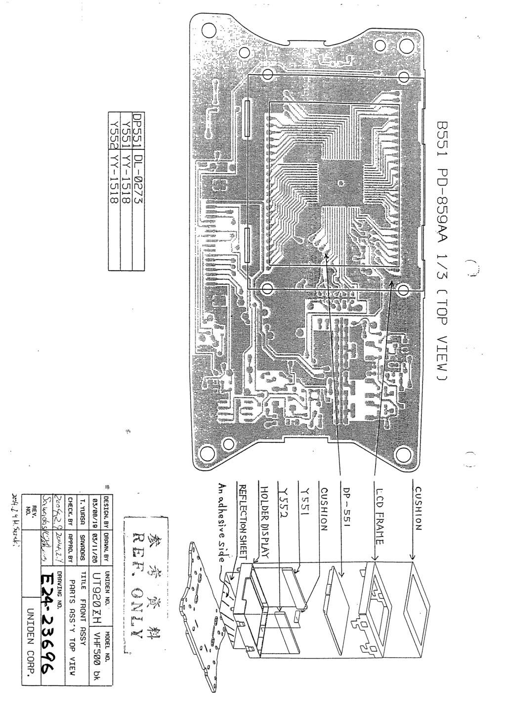
19 2. DESIGN 2.1. FRONT DESIGN MODE CH This design has some difference from real thing TOP DESIGN ( None ) 8

20 2.3. HAND MIC DESIGN This design has some difference from real thing. 9
21 3. CONTROLS AND FUNCTIONS 3.1. FRONT Switch [POWER/VOLUME] knob Turns this radio on and off as well as adjusts the audio volume [SQUELCH] knob Sets the point at which random noise on the channel does not activate the audio circuits but a received signal does [ ], [ ] key [ ] is able to move up the channels. [ ] is able to move down the channels. [ ] is able to move up an item of Menu. [ ] is able to move down an item of Menu [SELECT] key An item is decided by pushing this key in Menu mode [MENU] key Push this key to appear Menu Command. These options will control the following categories; DSC CALL, SETUP, and SYSTEM within each of these categories, there will be Submenu options that are outlined in the attached document [HI/LO] key Push this key to change output power [16/9 /TRI] key Pushing this key immediately recalls EMG 16CH from any location except 16CH. Next push this key to recall EMG 9CH. Pushing this key again reverts the radio to the previous select channel. Pushing and holding this key for 2 seconds will activate the triple watch feature [STEP/SCAN] key Push this key to activate the step operation. Every time this key is pushed, the radio will step to the next channel that has been placed into Memory. Pushing and holding this key for 2 seconds will activate the channel scan feature. 10
22 [MEM] key Push this key to add the current channel to scanning memory. Pushing this key again, it will delete the channel from scanning memory. This key will press and hold, it is possible to select USA / International / Canadian mode. (Hidden feature) [PA] key Push this key to enable the PA(Public Address) feature. This key will press and hold, it is possible to select Inlandwater way / Seagoing mode [DISTRESS] key Push this key to call an emergency. If it does so, a rescue signal will send towards a surrounding vessel. 11
23 3.2. MIC Switch [PTT] key This key will be pushed to send a transmission [ ] [ ] key Same as P.10 [3.1.3 [ ], [ ] key] [MENU] key Same as P.10 [3.1.5 [MENU] key] [CLR] key Delete a character [SELECT] key Same as P.10 [3.1.4 [SELECT] key] TEN keys a) For Entry Channel No., GROUP/USER MMSI, and DIRECTORY menu 1 press b) For Name data entry in DIRECTORY Menu 1 A D G J M P T W _ 2 presses - B E H K N Q U X <Blank> 3 presses = C F I L O R V Y ( 4 presses / S 8 Z ) 5 presses < presses > \ 7 presses presses * 9 presses 1 12
24 4. LCD DISPLAY TX LO HI U I C DSC TRI MEM This area is used for Channel Tag, Menu, and message of DSC, GPS. These messages will continually scroll from right to the left. 13
25 4.1. ICON Detail ICON TX DSC LO HI TRI WX ( TX Icon) DETAIL This icon is turned on during transmitting. This icon will be displayed when the radio is in the DSC mode, including receiving DSC Call. This icon is turned on when the transmit power is a less than 1W output. This icon is turned on when the transmit power is a less than 25W output. This icon is the mode that can receive EMG 16CH, EMG 9CH and current channel are scanning by turns. This icon is turned on (Blink) when Inlandwater way mode active. U I C MEM ( ALARM Icon) U icon is turned on when the channel is in USA mode. I icon is turned on when the channel is in International mode. C icon is turned on when the channel is in Canada mode. Note : These icons indicate in U.I.C. (Hidden feature) function. This icon is turned on when the current channel is a memory channel. This icon is turned on when the ALARM function is turned on. This icon (no waves) is turned on when GPS data is invalid. These icons are turned on when GPS data is effective. 14
26 seg. Character Pattern CHR FONT CHR FONT CHR FONT CHR FONT CHR FONT CHR FONT CHR FONT Blank A B C D E F CHR FONT CHR FONT CHR FONT CHR FONT CHR FONT CHR FONT CHR FONT G H I J K L M CHR FONT CHR FONT CHR FONT CHR FONT CHR FONT CHR FONT CHR FONT N O P Q R S T CHR FONT CHR FONT CHR FONT CHR FONT CHR FONT CHR FONT CHR FONT U V W X Y Z 1 CHR FONT CHR FONT CHR FONT CHR FONT CHR FONT CHR FONT CHR FONT CHR FONT CHR FONT CHR FONT CHR FONT CHR FONT CHR FONT CHR FONT 9 0 ( ) * + CHR FONT CHR FONT CHR FONT CHR FONT CHR FONT CHR FONT CHR FONT - / < = CHR FONT CHR FONT CHR FONT CHR FONT CHR FONT CHR FONT CHR FONT _ 15
27 5. OPERATIONS 5.1. POWER ON/OFF This knob will be rotated in a clockwise direction in order to turn the radio on. Upon turning the radio on there will be a click feel and a Wake Up Tone with message of RT-2500 > MMSI : XXXXXXXXX. (XXXXXXXXX = User MMSI Data or NO DATA ) As the knob is rotated clockwise, each volume level will have a click feel up to the maximum volume level. Upon turning on the radio, the channel displayed will be the last channel selected before the radio was turned off. The first time the radio is turned on, channel 16 will be selected. LO MEM 5.2. Channel Select [ ] key is used to scroll up through the channels. [ ] key is used to scroll down through the channels. If either [ ] or [ ] keys are held down for an interval of 0.5 seconds, the channel display will quickly scroll in the direction of the appropriately held key. The radio will sounds Key Tone (Single) only when [ ] or [ ] keys was pushed. << [ ] key >> << [ ] key >> User can select channel number by [TEN] Key and [SELECT] Key. Example. 1 : Push [1] key. 2 : Push [2] key. 3 : Push [SELECT] key. => The channel number will change to 12 Channel 70 is used DSC only, user cannot select channel
28 5.3. Transmission Push and hold [PTT] key, the TX icon on the LCD is displayed. While the user pushes [HI/LO] key while the radio has transmitted by low power, it is possible to output high power. Transmit time is limited to 5 minutes. TX icon and channel number blinks when transmit time is over 5 minutes. This prevents unintentional transmissions. (The radio cannot transmit on 15CH(USA) by [PTT] key.) TX LO MEM NOTE The ATIS signal shall be transmitted at the end of each transmission. The end of a transmission is considered to be every release of [PTT] key. When the radio is turned on while [PTT] key is held down, PTT Error Tone sounds, the channel indicator and TX icon blinks. All key except [HI/LO] key is not accepted during transmitting HI/LO POWER Pushing [HI/LO] key will change the transmit output power for the currently selected channel from HI (less than 25W) to LO (less than 1W) or from LO to HI depending on the current setting. Push [HI/LO] key, turn on LO icon; the transceiver can transmit with less than 1W. Once again, if this key is pushed, it will change to HI icon, the transceiver can transmit with less than 25W. The radio can t switch TX Power when it is scanning of SCAN mode. LO HI MEM [HI/LO] key MEM 17
29 5.5. MENU Push [MENU] key to change to Menu mode. Next push [MENU] key to cancel from Menu mode. These options in the Menu mode will control the following categories: DSC CALL, SETUP, and SYSTEM. [ ] key is used for scrolling down through the item of Menu. [ ] key is used for scrolling up through the item of Menu. [SELECT] key is used to select the item of Menu. [MENU] key is used to change up class of Menu. LO MEM [MENU]key [ ]key [ ]key [MENU]key [ ]key [ ]key [ ]key [ ]key Exit Menu [SELECT]key 18
30 MENU DSCCALL SETUP SYSTEM EXIT INDIVIDUAL ALARMCLOCK CONTRAST GROUP LOCALTIMEADJUST LAMPADJUST ALLSHIPS DAYLITESAVE KEYBEEP POSREQUEST DIRECTORY EXIT POSSEND AUTOCHSW STANDBY POSREPLY CALLWAIT CHTAG EXIT GROUPMMSI USERMMSI ATISID EXIT NOTE POS SEND, LOCAL TIME ADJUST, DAYLITE SAVE and ALARM CLOCK are not displayed in Menu when GPS module is not connected. EMG mode, Scan mode and Triple watch are canceled when the radio enter MENU. It will be canceled from MENU when the radio is transmitted and takes DSC Call. When [DISTRESS], [PTT] key is pushed, it will be canceled from MENU mode. When Inlandwater way Mode, INDIVIDUAL, GROUP, ALL SHIPS, POS REQUEST and POS SEND are not selected. (Error Tone) 19
31 DSC CALL Menu [SELECT]key [ ]key [ ]key [ ]key [ ]key [MENU]key [ ]key [ ]key Exit Menu [MENU]key (2S) [ ]key [ ]key [ ]key [ ]key [ ]key [ ]key [ ]key [ ]key Exit Menu [SELECT]key 20
32 INDIVIDUAL CALL Menu Example: LO DSC MEM [SELECT]key [ ]key [ ]key [MENU]key [ ]key [ ]key Exit Menu [MENU]key (2S) [ ]key [ ]key Exit Menu [SELECT]key [SELECT]key LO DSC MEM To Manual Input [SELECT]key (Select Inter-ship channel) 21
33 LO DSC MEM Select Inter-ship Channel by [ ] or [ ]key. [ ]key : CurrentCH->06CH->08CH->09CH->10CH ->13CH->15CH->17CH->67CH->69CH-> 72CH->73CH->77CH->CurrentCH Example : [ ]key [ ]key: CurrentCH->77CH->73CH->72CH->69CH ->67CH->17CH->15CH->13CH->10CH ->09CH->08CH->06CH->CurrentCH LO DSC Note : Group Call also is able to select inter-ship channel same as Individual Call. [SELECT]key DSC 22
34 TX DSC HI TX Power : High Individual Call is sent with High Power. LO MEM Return to idle screen. Receive the ACK. LO DSC MEM 23
35 Manual Input (ID) Example: [1]key [CLR]key [2]key [3]key [4]key [5]key [6]key [7]key [8]key [9]key [MENU]key NOTE: [ ]key is used to change cursor position to right in Manual Input(Menu). [ ]key is used to change cursor position to left in Manual Input(Menu). [SELECT]key LO DSC MEM Select Inter-ship channel 24
36 GROUP CALL Menu Example: DSC LO MEM [SELECT]key [SELECT]key LO DSC MEM Select Inter-ship channel Select Inter-ship Channel by [ ] or [ ]key. Same as [ INDIVIDUAL CALL Menu]. Example : [ ]key LO DSC [SELECT]key 25
37 DSC TX DSC LO TX Power : Low LO MEM Return to idle screen. Group Call is sent with Low Power. 26
38 ALL SHIPS CALL Menu Example: DSC LO MEM [SELECT]key [ ]key [ ]key Exit Menu [MENU]key [MENU]key (2S) [ ]key [ ]key Exit Menu [SELECT]key [SELECT]key DSC 27
39 TX DSC LO Routine : TX Power Low Other : TX Power High HI MEM Return to idle screen. 28
40 POSITION REQUEST CALL Menu Example: DSC LO MEM [SELECT]key [ ]key [ ]key Exit Menu [MENU]key [MENU]key (2S) [ ]key [ ]key [ ]key [ ]key Exit Menu [SELECT]key [SELECT]key [SELECT]key DSC Same as INDIVIDUAL CALL (Manual Input) 29
41 TX DSC HI TX Power : High (Position Request Call is sent with High Power.) LO MEM Return to idle screen Receive the Reply. LO DSC MEM UTC Time 30
42 POSITION SEND Menu Example: DSC LO MEM [SELECT]key [ ]key [ ]key Exit Menu [MENU]key [MENU]key (2S) [ ]key [ ]key [ ]key [ ]key Exit Menu [SELECT]key [SELECT]key DSC [SELECT]key Same as INDIVIDUAL CALL (Manual Input) 31
43 TX DSC HI TX Power : High Position Send Call is sent with High Power. 32
44 STANDBY Menu Example: LO MEM [SELECT]key 33
45 CALL WAIT Menu Example: Log DSC [SELECT]key [ ]key [ ]key Exit Menu [MENU]key [MENU]key (2S) [ ]key [ ]key Exit Menu [SELECT]key [SELECT]key [SELECT]key INDIVIDUAL CALL Log.. DISTRESS CALL Log. 34
46 DISTRESS CALL Log. Menu Example: DSC DSC [SELECT]key [ ]key [ ]key Ex.) If user has not checked the log, the log will be blinked. [MENU]key [ ]key [ ]key Exit Menu [MENU]key (2S) [ ]key [ ]key Exit Menu [SELECT]key [SELECT]key DSC [MENU]key [MENU]key (2S) Exit Menu 35
47 If the radio is not connected GPS, the log data have not the logged time. DSC 36
48 INDIVIDUAL CALL Log. Menu Example: DSC DSC [SELECT]key [ ]key [ ]key Ex.) If user has not checked the log, the log will be blinked. [MENU]key [ ]key [ ]key Exit Menu [MENU]key (2S) [ ]key [ ]key Exit Menu [SELECT]key [SELECT]key DSC [MENU]key [MENU]key (2S) Exit Menu [SELECT]key If the radio is not connected GPS, the log data have not the logged time. 37
49 LO DSC MEM Example : [ ]key Select Inter-ship Channel by [ ] or [ ]key. Same as [ INDIVIDUAL CALL Menu]. LO DSC [SELECT]key DSC TX DSC HI TX Power : High Same as INDIVIDUAL CALL Menu 38
50 NOTE DSC If ID of KENT NEWMAN is memorized in directory already, KENT NEWMAN will be indicated. If this ID is not memorized in directory, this ID will be indicated. 39
51 SETUP Menu This section has explained about Setup of this radio. Items in Setup Menu are as follows. ALARM CLOCK LOCAL TIME ADJUST DAYLITE SAVE DIRECTORY AUTO. CH.SW POS. REPLY CH TAG GROUP MMSI USER MMSI ATIS ID 40
52 [SELECT]key [ ]key [ ]key [ ]key [ ]key [MENU]key [ ]key [ ]key [ ]key [ ]key Exit Menu [MENU]key (2S) [ ]key [ ]key [ ]key [ ]key [ ]key [ ]key [ ]key [ ]key [ ]key [ ]key Exit Menu [SELECT]key [ ]key [ ]key 41
53 ALARM CLOCK Menu This feature will allow the user to set the alarm based on satellite time only if GPS is connected to the NMEA0183 jack. This option will only appear in the options list if a GPS is added to the unit. When set-up time comes, the radio will generate alarm. While alarm is generated, ALARM icon blinks. Push any key, in order to cancel alarm and disappear the ALARM icon. Example: [SELECT]key [MENU]key (not Memory) ( ALARM On/Off Select Screen ) [ ]key [ ]key [SELECT]key [MENU]key (2S) [SELECT]key (ALARM On) (not Memory) (ALARM Off) Exit Menu Exit Menu Exit Menu [SELECT]key (2S) ALARMTimeSet 42
54 ALARM On/Off Select Screen ( ALARM Time Set ) [CLR]key [1]key [MENU]key (not Memory) [0]key Exit Menu [MENU]key (2S) (not Memory) [2]key [SELECT]key (2S) [4]key [2](A)key [SELECT]key LO MEM NOTE: [ ]key is used to change cursor position to right. [ ]key is used to change cursor position to left. 43
55 LOCAL TIME ADJUST Menu This feature allows to adjusting local time 1H to + 1H. The following screens illustrate how to select this feature. [SELECT]key [SELECT]key (Memory) [MENU]key (not Memory) (LocalAdjust) [ ]key [ ]key Local Time +1H Local Time +0H [ ]key [ ]key Exit Menu [MENU]key (2S) (not Memory) Local Time 1H 44
56 DAYLITE SAVE Menu This feature allows changing the summer time is turned on or off. The following screens illustrate how to select this feature. [SELECT]key [SELECT]key (Memory) [MENU]key (not Memory) [ ]key [ ]key Summer Time : On Summer Time : Off [MENU]key (2S) (not Memory) Exit Menu 45
57 DIRECTORY Menu Example 1: directory [SELECT]key [ ]key [ ]key [MENU]key [ ]key [ ]key Exit Menu [MENU]key (2S) [ ]key [ ]key Exit Menu [SELECT]key 46
58 Example 2: Set New Data [SELECT]key [2]key [CLR]key [2]key [MENU]key (not Memory) [2]key x 2 Exit Menu [MENU]key (2S) (not Memory) [SELECT]key [3]key [SELECT]key(2S) [SELECT]key ( [SELECT]key x 9 ) [SELECT]key NOTE: [ ]key is used to change cursor position to right. [ ]key is used to change cursor position to left. 47
59 Exit Menu [MENU]key (2S) (not Memory) Same as Manual Input (ID) [MENU]key (not Memory) [SELECT]key(2S) (Memory) [SELECT]key (Memory) 48
60 Example 3: Edit Data [SELECT]key [ ]key [ ]key [MENU]key Exit Menu [ ]key [ ]key [MENU]key (2S) Exit Menu [SELECT]key [SELECT]key Name Edit ID Edit ( same as Set New Data ) 49
61 Example 4: Delete Data [ ]key [ ]key [SELECT]key [ ]key [ ]key [ ]key [ ]key [SELECT]key [ ]key [ ]key [ ]key [ ]key Data of KENT NEWMAN is deleted, and change position to next data. 50
62 AUTO CH SW Menu This feature allows disabling the automatic channel change that happens when receiving a DSC Call. The following screens illustrate how to select this feature. [SELECT]key [SELECT]key (Memory) [MENU]key (not Memory) [ ]key [ ]key AUTO CH SW : On AUTO CH SW : Off [MENU]key (2S) (not Memory) Exit Menu 51
63 POS REPLY Menu When this radio is requested the position data by other vessel, the user can decide to transmit the ACK automatically or manually. [SELECT]key [SELECT]key (Memory) [MENU]key (not Memory) [ ]key [ ]key POS REPLY : On(Auto) POS REPLY : Off (Manual) [MENU]key (2S) (not Memory) Exit Menu 52
64 CH TAG Menu This feature allows setting name each MRN channel. (The user can name for the channel of each of U.I.C mode.) Max character of the TAG is 12digits. Example 1: [SELECT]key [ ]key [ ]key [MENU]key Exit Menu [MENU]key (2S) [ ]key [ ]key 53
65 Example 2: Edit Data [SELECT]key Same as Edit of DIRECTORY Name [MENU]key (not Memory) Exit Menu [MENU]key (2S) (not Memory) [SELECT]key (2S) (Memory) 54
66 GROUP MMSI Menu Group MMSI is composed by number of 9 digits. This MMSI is used to Group Call. group MMSI [SELECT]key [MENU]key (not Memory) Same as Manual Input (ID) Exit Menu [MENU]key (2S) (not Memory) [SELECT]key (2S) (Memory) [SELECT]key (Memory) Note : The first digit of a Group MMSI is preselected 0 in the radio. 55
67 USER MMSI Menu USER MMSI is composed by number of 9 digits. The specifications for this feature state that the radio can only be programmed 1 time. If the radio needs changing the MMSI 2times, the user should send back to Uniden for reprogramming. User MMSI [SELECT]key [CLR]key Same as Manual Input (ID) [MENU]key (not Memory) Exit Menu [MENU]key (2S) (not Memory) [SELECT]key (2S) (Memory) [SELECT]key (Memory) 56
68 ATIS ID Menu The ATIS ID is composed by number of 10 digits. The first digit of ATIS ID is preselected 9 in the radio. The ATIS ID can only be entered once. If it is necessary to change the ATIS ID, the user should send back to Uniden for reprogramming. *ForATISIDprogramming 1. The unit power supply is turned on pushing [HI/LO]key and [MENU]key. ATIS ID Usually, only a check is. [SELECT]key [MENU]key (not Memory) Same as Manual Input (ID) Exit Menu [MENU]key (2S) (not Memory) [SELECT]key (2S) (Memory) [SELECT]key (Memory) 57
69 SYSTEM Menu This section has explained about setting of System of this radio. Items in System Menu are as follows. CONTRAST LAMP ADJUST KEY BEEP [SELECT]key [ ]key [ ]key [MENU]key [ ]key [ ]key Exit Menu [MENU]key (2S) [ ]key [ ]key Exit Menu [SELECT]key 58
70 CONTRAST Menu This option allows changing the contrast levels of the LCD. The contrast can be set as 0-7 levels continuously. The each level has adjusting of 5step. [SELECT]key [SELECT]key (Memory) [MENU]key (not Memory) [ ]key (*1) [ ]key(*1) [MENU]key (2S) (not Memory) Exit Menu *1 : Push and hold the key. 59
71 LAMP ADJUST Menu The feature allows changing the brightness level of the back lighting of the LCD screen and the keys. The brightness can be set as 4 levels. [SELECT]key [SELECT]key (Memory) [MENU]key (not Memory) [ ]key [ ]key [MENU]key (2S) (not Memory) Exit Menu 60
72 KEY BEEP Menu This feature allows changing the Key Beep (Key Tone, Error Tone and Wake Up Tone) is enabled (on) or disabled (off). [SELECT]key [SELECT]key (Memory) [MENU]key (not Memory) [ ]key [ ]key [MENU]key (2S) (not Memory) Exit Menu 61
73 CH / 9CH Pushing [16/9 /TRI] key immediately recalls EMG 16CH from any location except when current channel is 16CH. ( But if Triple watch mode is ON, the channel will change to EMG 16CH. ) And the transmit output power will change to HI in 16CH. Next push [16/9 /TRI] key to recall EMG 9CH. Pushing [16/9 /TRI] key again reverts the radio to the previous select channel. LO MEM HI CAN When [16/9 /TRI] key is pushed on conditions that Scan mode or Triple watch mode is ON, Scan mode or Triple watch mode is stopped temporarily. When [PTT] key is pushed on condition that EMG mode is ON, Triple watch mode or Scan mode has be canceled. When [16/9 /TRI] key is pushed when Triple watch mode or Scan mode has stopped temporarily, then these modes will be recalled. When [16/9 /TRI], [ ], [ ], and [STEP/SCAN] key is pushed, EMG mode is canceled. HI MEM Push [16/9] key Push [16/9] key LO MEM Push [16/9] key 62
74 5.7. Memory Channel Set / Cancel Pushing [MEM] key to store the memory with the current MRN CH by not memory channel, MEM icon appears. On/Off Pushing [MEM] key to remove the memory of channel, and MEM icon disappears. LO MEM NOTE (Memory Channel can be set up by mode of USA, INT, and CAN.) If the radio is SCAN mode with scanning, the channel can t be set. Pushing [MEM] key while staying the channel that is scanning, the channel will be canceled the memorized channel. If repeat the above-mentioned operation, a memory channel is turned off. If the memorized channel becomes only one channel, scan mode will turn off and will turn into MRN Idle mode. Only one memorized channel is set as current channel. It cannot be cancel all memory channels at the same time. 63
75 5.8. Triple Watch This function carries out scan of 9CH, 16CH, and current channel. Pushing and holding [16/9 /TRI] key for 2 seconds in state of Triple watch off, it is set to Triple watch on, TRI icon and message of TRIPLE WATCHING appears. LO TRI MEM On/Off Pushing and holding [16/9 /TRI] key for 2 seconds in state of Triple watch on, it is set to Triple watch off, and TRI icon and message of TRIPLE WATCHING disappears. NOTE Triple watch receives EMG 16CH, EMG 9CH, and Current CH by turns. If 9CH is busy, Triple watch receives EMG 9CH and EMG 16CH by turns. If 16CH is busy, Triple watch only receives EMG 16CH. If Triple watch is in EMG mode, Triple watch receives EMG 16CH, EMG 9CH and last MRN CH(16 or 9). If user pushes [16/9 /TRI] key in Triple watch, Triple watch will be interrupted temporarily and it will be set to EMG 16CH. If user pushes [16/9 /TRI] key once again, it will be set to EMG 9CH, and Triple watch will be resumed if user pushes [16/9 /TRI] key once again. Triple Watch will be resumed if a signal of EMG CH is lost for 3 seconds (Drop Out Delay Timer) in the EMG CH Stay state of Triple Watch On. When [DISTRESS] key and [PTT] is pushed, Triple Watch mode is canceled. 64
76 5.9. Scan mode This feature will allow the user to scan the memorized channels. Pushing and holding [STEP/SCAN] key for 2 seconds in scan mode off, it is set to Triple watch scan on, CHANNEL SCANNING is indicated on 14seg. And TRI icon appears. Pushing and holding [STEP/SCAN] key for 2 seconds in scan mode on, it is set to scan mode off. When [DISTRESS] or [PTT] key is pushed, SCAN mode is canceled. LO TRI MEM If the radio has detected a signal, the CH digits are displayed a stay channel. If [ ] key is pushed while scan is staying, the memory channel can restart scanning. If a signal stopped when the radio is staying a channel in Scan mode, then the radio wait to detect a signal for 3 seconds (Drop out Delay Timer). But if a signal wasn t detected, then restart to scan. LO TRI MEM Pushing and holding [STEP/SCAN] key for 2 seconds by EMG 16CH or EMG 9CH, EMG 16CH or EMG 9CH will be canceled and Triple watch scan will be started. When one does not have Memory channel, it is not set to scan mode and ring the Error Tone even if it pushed [STEP/SCAN] key. Pushing and holding [STEP/SCAN] key for 2 seconds at the time only a memory channel, it will be set to the Memory channel, without being set to scan mode. Push [PTT] key or [SCAN] key in SCAN mode (Triple Watch) Scan mode will be OFF. Current channel become as following Scanning Scanning CH Scan Stay Stay Channel 16CH Watch Stay 16CH 9CH Watch Stay 9CH 65
77 Triple watch scan Pushing and holding [STEP/SCAN] key for 2 seconds in scan mode off, it is set to Triple watch scan on, CHANNEL SCANNING is indicated on 14seg. and TRI icon appears. Although current channel is scanned, EMG 16CH and EMG 9CH are watched every 2 seconds. "TRI" turn on. Triple watch scan is not performed when the memory is not registered. LO TRI MEM Normal scan To Normal scan is turned on, pushing and holding [16/9/TRI] key for 2 seconds in Triple watch scan mode. Although Memory channel is scanned, EMG 16CH and EMG 9CH are not watched in Normal scan. Normal scan is not performed when the memory is not registered. LO MEM 66
78 5.10. Distress This feature will allow the user to transmit a Distress Call. In order to transmit a Distress Call, push [DISTRESS] key for 5 seconds. And select nature code. Then push [SELECT] key. Distress Call is sent with High Power (less than 25W). LO MEM Count down 4S 1S count down DSC If channel 70 is free, it transmits a Distress Call automatically TX HI DSC TX Power : High 67
79 The radio shadow-watches for a transmission between CH16 and CH70 until an acknowledgment signal is received. If user push [16/9 /TRI], it is canceled the Distress Call. HI DSC Then the Distress Call has been sent, the Distress alert will sound. Distress Call is transmitted and it waits for about seconds. This is continued until an acknowledgment signal is received.. Distress Ack Wait If this radio received an acknowledgment signal, as shown in the following screen. HI DSC The name will be displayed if it is the name registered into the directory. Otherwise, MMSI is displayed. 68
80 If this radio takes a Distress Call, it will be displayed such as the following screen and an emergency alarm sounds. The screen will display a message with calling radio s MMSI(or Name), nature code, time (hour/minute) and position (degree/minute; second data = 000 ). If the data of caller radio is attached second data of position, this radio will display second data too. (This radio support the second data of position for Distress/Position Request Call) HI DSC Nature Code FIRE FLOODING COLLISION GROUNDING CAPSIZING SINKING ADRIFT ABANDONING PIRACY/ARMED OVERBOARD UNDESIGNATED 69
81 If the radio receives a Distress Call without GPS data, the position data indicate as below. HI DSC A) Even if the radio has already displayed message screen, if the radio received a DSC Call, it will display a new message instead of old message B) If the user pushes any key when message screen is displayed, the message screen is disappeared. C) Even if the user doesn t push any key, the radio will stop DSC Routine Tone or DSC Distress Tone automatically. (When STANDBY mode is OFF, the tone stop after 5 minutes. When STANDBY mode is ON, the DSC Distress Tone stop after 30 sec, the DSC Routine Tone stop after 5 sec) D) The radio don t watch 70CH if the signal of current channel is busy. So the radio can t receive DSC Call when signal is busy. E) When the radio send DSC Call, Channel Display change to 70CH temporarily and check whether a signal (on 70CH) is busy. If signal is busy the radio will wait until signal isn t busy. If signal isn t busy the radio will send a DSC Call (If [16/9 /TRI] key was pushed, the radio cancel to send DSC Call). F) When the radio received DSC Call, the radio is canceled SCAN, TRIPLE WATCH, EMG function/mode. G) A) F) are common operation of All DSC Call. 70
82 5.11. DSC Call Individual Please refer to P.21 [ INDIVIDUAL CALL Menu] about transmit Individual Call. Individual Call is sent with High Power. DSC Call Tone (Routine) will sounds when receive the ACK after sending Individual Call. It will stop the tone to push any key. If the calling vessel has already set STANDBY mode, it will display the following. LO DSC MEM 71
83 If this radio takes the Individual Call, it will be displayed the following screen and an emergency alert sounds. The name will be displayed if it is the name registered into the directory; otherwise MMSI is displayed with category code. If user reply the Individual Call push [SELECT]key. If cancel to reply the call, push [MENU] or [CLR]key. LO DSC MEM Category Code DISTRESS URGENCY SAFETY ROUTINE SHIP BUSINESS Example: Radio one makes an Individual Call on 18CH and radio two is on 20CH. The receiving radio will automatically change to 18CH once the signal is received. The receiving radio will also display the name that has called and the indicator of INDIVIDUAL NOTE When the call is first made both radios will display 70CH while the signal is received. After all of the data is received, the receiving radio will change channels to the channel that the transmitting radio first sent the transmission out on. 72
84 Group Please refer to P.25 [ GROUP CALL Menu] about transmit Group Call. Group Call is sent with Low Power. If Group MMSI registered beforehand is the same, it will be possible to communicate. If this radio has received Group Call, the following screen display on LCD and sounds DSC Call Tone. To stop the tone, push any key. Push any key again, it will return to idle screen. LO DSC MEM 73
85 All Ships Please refer to P.27 [ ALL SHIPS CALL Menu] about transmit All Ships Call. ROUTINE is sent with Low Power. The others are sent with High Power. This function will be used to send a message to all vessels. There will be three types of transmissions that may be sent, URGENCY, SAFETY and ROUTINE. If this radio is received from other vessel, it will display the following screen. When sending either an URGENCY or SAFETY message, both radios will automatically move to 70CH until all of the data is received and then both radios will go to 16CH for transmissions and replies. The ROUTINE transmission will go to 70CH until all data is transmitted, and then both radios will go to the channel that the transmission originated from. HI DSC MEM Category Code 74
86 POS. REQUEST Please refer to P.29 [ POSITION REQUEST CALL Menu] about transmit Position Request Call. Position Request Call is sent with High Power. This function will be used to request that the position of the vessel registered into the directory should be transmitted. When this radio is requested the position data by other vessel, it will display the following screen. "POS.REPLY" is set up as Auto. LO DSC MEM When this radio is requested to the position data by other vessel, it will display the following screen. "POS.REPLY" is set up as Off. If reply a position request, push [SELECT]key. If cancel to reply a position request, push [MENU]key. LO DSC MEM 75
87 If this radio receives POS. REPLY, the following screen appears. The screen will display a message with calling radio s MMSI(or Name), time (hour/minute) and position (degree/minute; second data = 000 ). If the reply data is attached second data of position, this radio will display second data too. (This radio support the second data of position for Distress/Position Request Call) LO DSC MEM If this radio receives POS. REPLY without GPS data, the following screen appears. LO DSC MEM 76
88 POS. SEND Please refer to P.31 [ POSITION SEND Menu] about transmit Position Send Call. Position Send Call is sent with High Power. This function will be used to transmit that the position of the vessel registered into DIRECTORY should be transmitted. The position information include not only degree and minute but also second. If this radio receives POS. SEND, the following screen appears. LO DSC MEM Geographical Call This function can receive the electric wave transmitted towards the vessel that is present in the domain specified from the call side. This operation will display the following screen. This radio is impossible to transmit the Geographical Call. Only receive. The time that received the Geographical Call is displayed. LO DSC MEM 77
89 Standby Please refer to P.33 [ STANDBY Menu] about set this mode. This radio will allow the user to place the radio in an unattended mode. This will not allow an incoming DSC Call. The user will need to place the radio in this mode if they will be away from the radio and not wish to answer any calls. The following screen will appear to let the user know that the STANDBY mode has been activated. LO MEM If any calls is received in standby state, it will be indicated the call message. When this mode is activated if the radio received DSC Call, it is as following. Individual Call It will automatically reply NACK to the call on channel 70 and then change to calling radio s channel. The call is memorized as Call Wait Log. Distress Call The call is memorized as Call Wait Log. Other Call These Calls aren t memorized as Call Wait Log. The user can push any key or [PTT] key to deactivate this feature. The radio will automatically reply to the call on 70CH same as when the radio is not STANDBY mode. 78
90 Auto Channel Switch Please refer to P.51 [ AUTO CH SW Menu] about set this mode. If the radio received DSC Call when AUTO CH SW mode is OFF, it will display message screen and sound DSC Call Tone (Routine). But the channel doesn t change. If received Individual Call, this radio will reply that it is unattended. The user can deactivate this feature by Auto CH SW Menu only. When this mode is activated the radio will receive DSC Call Tone (Routine) indicating that a call is coming in. The radio will automatically reply to the call on 70CH and then return to the working channel. * Auto ch switch setting is ignore, when All DSC calls of category distress or urgency or DISTRESS CALL are received Call Wait Please refer to P.34 [ CALL WAIT Menu] about use this feature. This feature allows the user to view a list of received calls that came into the radio while either in STANDBY mode or if a call timed out after 5 minutes and went into the Call Wait log. Distress Call has 10 record able domains, and Individual Call has 20 record able domains. A new log is placed on the top of each Menu. If the number of logs is max, then the bottom log (most oldest log) is removed from memory Directory Please refer to P.46 [ DIRECTORY Menu] about use this feature. This function will allow the user to send an Individual Call etc. Directory is the function to memorize the name and number of 20 other vessels. The name can be inputted to within 12 characters. NOTE MMSI cannot be inputted if all the portions of a name are inputted by BLANK. 79
91 5.12. Step The user will push [STEP/SCAN]key to activate the step operation. If time this key is pushed, the radio will step to the next channel that has been placed into Memory. Please refer to P.63 [5.7 Memory Channel Set / Cancel] about use this feature U.I.C The unit power supply is turned on pushing [HI/LO]key and [SELECT]key for confirming private use which changes UIC. If the hidden feature (U.I.C.) is enabled, pushing and holding the [MEM]key for 2 seconds will change channel mode (USA to International, International to Canada, Canada to USA). The radio needs to remember which channel was last selected in each of U, I, C so that when the radio is switched modes the next time these modes are selected the last channel is displayed. Also, this will apply even if the radio is turned off. The initial default channel for each mode is channel 16. When U.I.C. mode is changed, Triple Watch mode, Scan mode, EMG mode are canceled. 80
92 5.14. Other Function GPS Display This section will explain the operations of GPS that this radio will be able to display based on an external GPS module being connected through the NMEA0183 jack. The radio meets the requirements of GPS by displaying date, time, latitude and longitude. Below is how the display will read based on having and external GPS module connected. The local time offset from UTC will automatically be applied based on current Lat/Long position. This will eliminate any need for a time offset screen. LO MEM The channel mode display information will be the priority and will be displayed whenever the radio receives an incoming transmission or when the radio is transmitting. The user can also toggle back and forth between the two displays by pushing [SELECT]key from the channel display screen. < GPS OK > 2 seconds MRNMode [SELECT]key GPSMode Other key MRNMode (exceptpa) 81
93 If user push [SELECT] key in MRN Mode and external GPS module unconnected, the radio will be GPS Setting Mode. The time is used UTC in this mode. < Not connect GPS > MRN Mode [SELECT]key GPS Setting Mode [SELECT]key Note : if external GPS modulate is not connected, and position data not input, GPS Icon will start blinking. If the position data is not change for 4hours, GPS Icon will start blinking. And if the position data is not change for 23.5hours, GPS setting data is cleared(no Data). 82
94 < GPS Setting Mode > LO MEM [SELECT]key GPS Setting Mode Manual GPS Mode [SELECT]key(2S) [0][8][2][3][1][0][3][4] [SELECT]key [SELECT]key(2S) [1][2][3][4][5][6][7][7(S)]key [SELECT]key [SELECT]key(2S) [1][3][5][7][9][2][4][6][3(E)]key Indicate Date and Position by scroll. (Blanks are fill uped with 0) [SELECT]key 83
95 PA The [PA]key will be used to activate the Public Address feature. When the PA key is pushed, the LCD screen will be as follows. Push and hold PTT on the microphone, and speak clearly in a normal voice. Pushing the [PA] key again will return the radio to the radio mode. Push PTT TX Public Address Hi/Lo Battery detect This feature will allow the user to detect a battery condition. The display of a battery is not performed when DSC is received. When the radio detect battery low (11V), appear the following screen. LO MEM When the radio detect battery high (16V), appear the following screen. LO MEM 84
96 GPS ANTENNA DETECT ICON Waves will move to show activity and connection with the satellite. If the external GPS modulate is not connected, and position data not input, GPS Icon will start blinking If the position data is not change for 4hours, GPS Icon will start blinking Last Channel Memory This radio indicates the memorized channel (the channel when shutting off = last channel) at time of turning on. The last channel is as below. Example, if you shut off the radio in EMG mode, the last channel will be current marine channel. 1: EMG mode => Current MRN CH 2: Scan Mode => Scan Start CH 3: Triple Watch Mode => Current MRN CH If you shut off the radio within 3 seconds from the channel is changed, the channel will be not memorized. (the last channel will be memorized to EEP Memory per 3 seconds.) Inlandwater way Mode/Seagoing Mode Push and hold [PA] key, "Inlandwater way Mode" of PA Key and "Seagoing Mode" are switched. Seagoing Mode The sending and receiving of DISTRESS/DSC is transmitted and ATIS can be transmitted. Inlandwater way Mode DISTRESS/DSC cannot be sent and received. ATIS can be transmitted. WX" icon blinks at active Mode. LO LO MEM MEM WX Seagoing Mode Inlandwater way Mode 85
97 Free CH active ON/OFF(Hidden feature) Transmission and reception of 30,31,L1, L2, L3, F1, F2, F3 and M1 of 9CH are enabled in addition to existing MRN CH. The unit power supply is turned on pushing [HI/LO]key and [SCAN]key. Active Mode(3 Mode)/Inactive of Free CH changes. It changes with Inactive -> Mode1 -> Mode2 -> Mode3 -> Mode4. Mode1 : L1/L2/F1/F2/F3 active Mode2 : L1/L2/L3/F1/F2/F3 active Mode3 : 30/31 active Mode4 : M1 active ( CH display is n1 ) CHANNEL SELECT Press [ ] key to increment the Channel number (L1) (L2) (F1) (F2) (F3) (M1) Press [ ] key to decrement the Channel number (L1) (L2) (F1) (F2) (F3) (M1) * Active/Inactive of Free CH becomes effective also at the time of Power On next time. 86
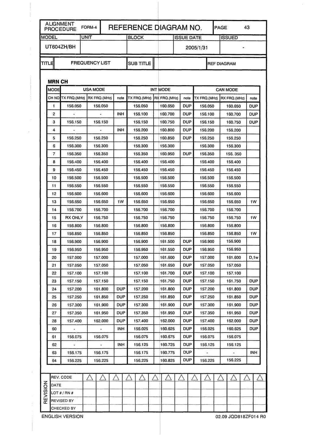
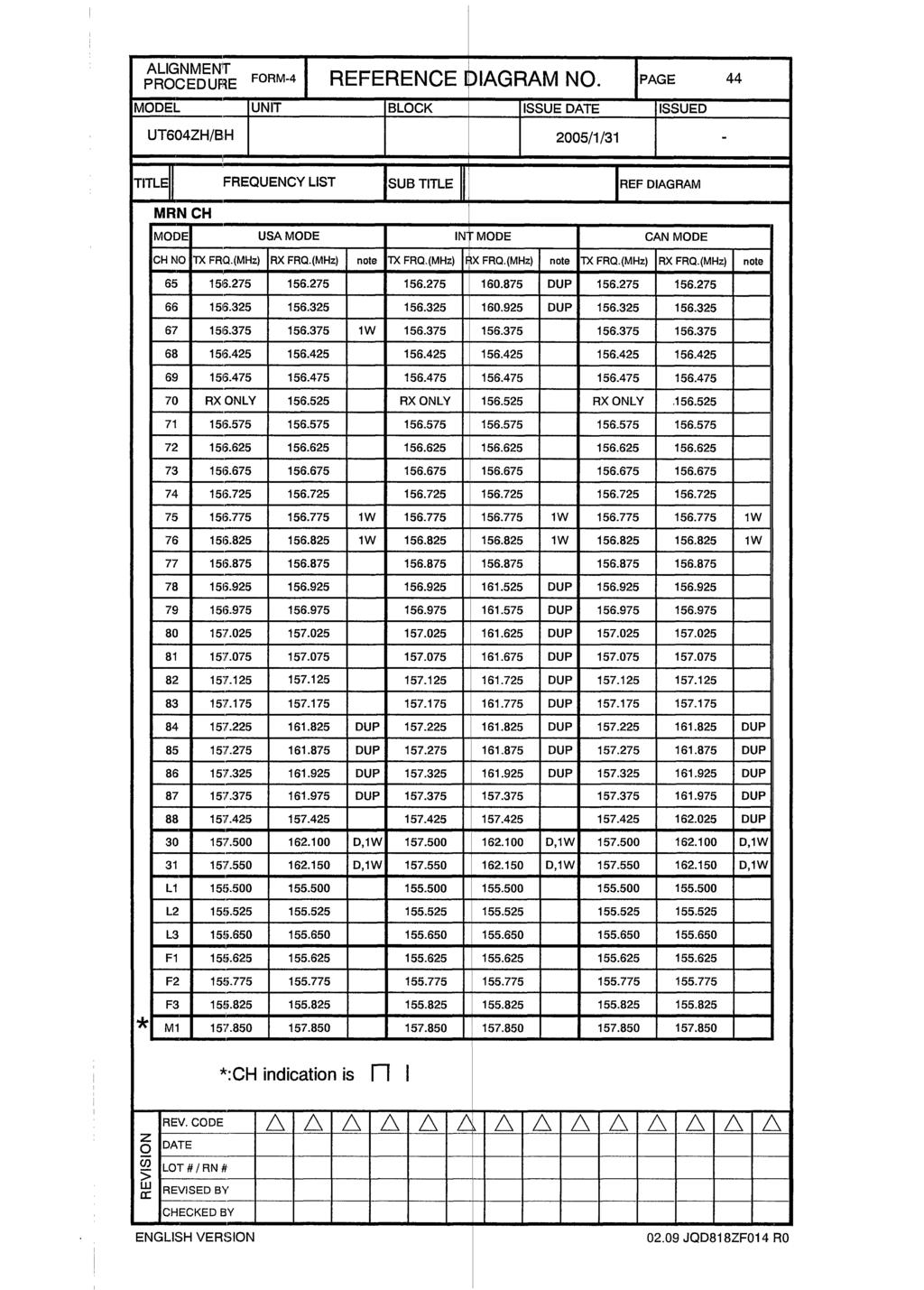
98 6. Reference 6.1. International Frequencies and Channels CH CH TAG S/D TX RX 01 TELEPHONE D TELEPHONE D TELEPHONE D INTL D INTL D SAFETY S INTL D COMMERCIAL S CALLING S COMMERCIAL S VTS S VTS S BRG/BRG S VTS S COMMERCIAL S DISTRESS S SAR S INTL D INTL D PORT OPR D INTL D INTL D INTL D TELEPHONE D TELEPHONE D TELEPHONE D TELEPHONE D TELEPHONE D TELEPHONE D INTL D INTL D INTL D TELEPHONE D INTL D
99 66 INTL D BRG/BRG S SHIP-SHIP S PLEASURE S DSC S (Only DSC) 71 PLEASURE S SHIP-SHIP S PORT OPR S PORT OPR S CH75 S CH76 S PORT OPR S INTL D INTL D INTL D INTL D INTL D INTL D TELEPHONE D TELEPHONE D TELEPHONE D TELEPHONE S TELEPHONE S
100 6.2. USA Frequencies and Channels CH CH TAG S/D TX RX 01 VTS S S VTS S SAFETY S COMMERCIAL S COMMERCIAL S CALLING S COMMERCIAL S VTS S VTS S BRG/BRG S VTS S COMMERCIAL S DISTRESS S SAR S COMMERCIAL S COMMERCIAL S PORT OPR S CCG S USCG S USCG S TELEPHONE D TELEPHONE D TELEPHONE D TELEPHONE D TELEPHONE D CCG S VTS S COMMERCIAL S PORT OPR S PORT OPR S BRG/BRG S SHIP-SHIP S PLEASURE S DSC S (Only DSC) 89
101 71 PLEASURE S SHIP-SHIP S PORT OPR S PORT OPR S CH 75 S CH 76 S PORT OPR S SHIP-SHIP S SHIP-SHIP S SHIP-SHIP S CCG S CCG S USCG S TELEPHONE D TELEPHONE D TELEPHONE D TELEPHONE D COMMERCIAL S
102 6.3. Canada Frequencies and Channels CH CHTAG S/D TX RX 01 TELEPHONE D TELEPHONE D TELEPHONE D INTL S VTS S SAFETY S COMMERCIAL S COMMERCIAL S CALLING S COMMERCIAL S VTS S VTS S BRG/BRG S VTS S COMMERCIAL S DISTRESS S SAR S COMMERCIAL S COMMERCIAL S PORT OPR D CCG S USCG S INTL D TELEPHONE D TELEPHONE D TELEPHONE D TELEPHONE D TELEPHONE D TELEPHONE D CCG S INTL S COMMERCIAL S PORT OPR S PORT OPR S BRG/BRG S
103 68 SHIP-SHIP S PLEASURE S DSC S (Only DSC) 71 PLEASURE S SHIP-SHIP S PORT OPR S PORT OPR S CH 75 S CH 76 S PORT OPR S SHIP-SHIP S SHIP-SHIP S SHIP-SHIP S CCG S CCG S USCG S TELEPHONE D TELEPHONE D TELEPHONE D TELEPHONE D TELEPHONE D Extend CH(Hidden feature) CH CH TAG S/D TX RX D CH D D CH D L1 CH L1 S L2 CH L2 S L3 CH L3 S F1 CH F1 S F2 CH F2 S F3 CH F3 S M1 CH M1 S
104 6.5. Only Low power CH The CH that use exclusive for low power is following. Seagoing Mode AREA CH CH CH CH CH CH CH CH INT USA CAN Inlandwater way Mode AREA CH CH CH CH CH CH CH CH INT USA CAN Tones Tone Key Tone (Single Tone) Key Tone (Double Tone) Error Tone PTT Error Tone Wake Up Tone DISTRESS send Tone DSC ACK Wait Tone DSC Call Tone (Distress) DSC Call Tone (Routine) Explanation This sounds when key is pressed. This sounds when key is pressed and held for 2 seconds. This sounds when pressed key is invalid. This sounds when [PTT] key is invalid. This sounds when the radio is powered on. This sounds when the radio Distress send. ([SELECT] key pressed) This sounds when the radio is DSC ACK waiting state. This sounds when Distress Call or DSC Call which category code is Distress or Urgency is decoded. This sounds when DSC Call which category code isn t Distress or Urgency is decoded. 93
105 6.7. Initialize MRN NO. FUNCTION STATUS 1 Channel CH16 2 SCAN OFF 3 TRIPLE WATCH OFF 4 EMG MODE OFF 5 TX POWER HI 6 Memory Channel All Channel OFF 7 Mode Seagoing Mode MENU - SYSTEM - NO. FUNCTION STATUS 1 CONTRAST 7 2 LAMP ADJUST 3 3 KEY BEEP ON MENU - SETUP - NO. FUNCTION STATUS 1 ALARM CLOCK ALARM : 0FF, 00:00A 2 LOCAL TIME ADJUST LOCAL TIME +0 3 DAYLITE SAVE OFF 4 DIRECTORY NONE 5 AUTO.CH.SW ON 6 POS.REPLY MANUAL 7 CH TAG See Frequencies and channels list 8 GROUP MMSI NONE 9 USER MMSI NONE 10 ATIS ID NONE 94
106
107
108
109
110
111
112
113
114
115
116
117
118
119
120
121
122
123
124
125
126
127
128
129
130
131
132
133
134
135
136
137
138
139
140
141
142
143
144
145
146
147
148
149
150
151
152
153
154
155
156
157
158
159
160
161
162
163
164
165
166
167
168
169
170
171
172
173
174
175
176
177
178
179
180
Service Manual for RTP-1000
 Service Manual for RTP-1000 Japan Marina Co., Ltd. Revision History No. DATE Contents Version Author 1 04/10/14 1.00 T.KOGURE 2 04/10/26 2 nd Releace 1.01 T.KOGURE 3 04/12/27 3 rd Releace 1.02 T.KOGURE
UM455 VHF DSC Marine Radio
 UM455 VHF DSC Marine Radio For more exciting new products please visit our website: Australia: www.uniden.com.au Making a distress call NOTE: There is no official VHF DSC shore infrastructure in Australia.
HM-162E. z HM-162E supplied accessories. x Function display INSTRUCTIONS REMOTE-CONTROL MICROPHONE. Thank you for purchasing the HM-162E REMOTE- q w e
 INSTRUCTIONS REMOTE-CONTROL MICROPHONE HM-162E Thank you for purchasing the HM-162E REMOTE- CONTROL MICROPHONE. The COMMANDMIC III TM is a remote control microphone for use with the IC-M603 or else. Please
VHF585 CLASS D MARINE RADIO MODEL (BLACK) / (WHITE) Owner s Manual
 / (WHITE) Owner s Manual") VHF585 CLASS D MARINE RADIO MODEL 16230534 (BLACK) / 16230542 (WHITE) Owner s Manual MAKING A DISTRESS CALL Lift the red cover. Press and hold the DISTRESS button for three seconds. Your radio transmits
VHF585 CLASS D MARINE RADIO MODEL 16230534 (BLACK) / 16230542 (WHITE) Owner s Manual MAKING A DISTRESS CALL Lift the red cover. Press and hold the DISTRESS button for three seconds. Your radio transmits
HM-162B/SW. z HM-162B/SW supplied accessories. x Function display INSTRUCTIONS REMOTE-CONTROL MICROPHONE
 INSTRUCTIONS REMOTE-CONTROL MICROPHONE HM-162B/SW Thank you for purchasing the HM-162B/SW REMOTE- CONTROL MICROPHONE. The COMMANDMIC III TM is a remote control microphone for use with the IC-M604 or else.
VHF 300 Series. owner s manual
 VHF 300 Series owner s manual VHF 300 Series Owner s Manual Introduction Introduction The VHF 300 series radios equip you with the ability to communicate on all International, USA, and Canadian marine
YCE13. Dealer PC Programming Software Reference Manual. Attention!
 YCE13 Dealer PC Programming Software Reference Manual Attention! The YCE13 programing software can only be used with HX380/400 firmware version Ver. 2.00 or later. This software is used to program the
VHF 110/210 AIS Series. Owner s Manual
 VHF 110/210 AIS Series Owner s Manual Table of Contents Introduction...1 Radio Overview... 1 Handset Overview... 1 Home Screen... 1 System Status Icons... 1 Basic Operation... 2 Turning On and Off the
Explorer 725 / 705. VHF Marine Radio Quickstart Guide.
 Explorer 725 / 705 VHF Marine Radio Quickstart Guide www.northstarnav.com This Quickstart Guide is to be used with the Northstar Explorer 721 VHF Radio Installation and Operation Manual. The Explorer 721
MC-8050 DSC. owner s Manual
 MC-8050 DSC owner s Manual MAkInG A DIstRess CALL Lift the red cover. Press and hold the DIstRess button for three seconds. Your radio transmits your boat s location every few minutes until you receive
VHF 100/200 Series. owner s manual USA DISTRESS. Š.Œ ƒ ˆ Š Œ. ˆ : ŒPM UTC WATCH PA SCAN 25W LOCAL
 VHF 100/200 Series owner s manual 25W 16 DISTRESS LOCAL WATCH PA SCAN USA Š.Œ ƒ ˆ Š Œ. ˆ : ŒPM UTC 2008 Garmin Ltd. or its subsidiaries Garmin International, Inc. 1200 East 151st Street, Olathe, Kansas
UM415 SUBMERSIBLE DSC MARINE RADIO RADIO MARITIME ASN OWNER S MANUAL GUIDE D UTILISATION
 UM415 SUBMERSIBLE DSC MARINE RADIO RADIO MARITIME ASN OWNER S MANUAL GUIDE D UTILISATION Making a Distress Call Lift the red cover. Press and hold the DISTRESS button for three seconds. Your radio transmits
VHF 110/210 AIS Series. Owner s Manual
 VHF 110/210 AIS Series Owner s Manual 2017 Garmin Ltd. or its subsidiaries All rights reserved. Under the copyright laws, this manual may not be copied, in whole or in part, without the written consent
VHF 115/215 AIS SERIES. Owner s Manual
 VHF 115/215 AIS SERIES Owner s Manual 2018 Garmin Ltd. or its subsidiaries All rights reserved. Under the copyright laws, this manual may not be copied, in whole or in part, without the written consent
VHF 7000, 7100US, 7100EU. Operation Manual NAVMAN
 VHF 7000, 7100US, 7100EU Operation Manual w w w. n a v m a n. c o m NAVMAN FCC Statement This equipment has been tested and found to comply with the limits for a Class B digital device, pursuant to Part
GX600D VHF MARINE RADIO INSTRUCTION MANUAL PRINTED IN ENGLISH INTERNATIONAL: 0168! USA : FCC ID : TXJGX600D CANADA : IC 7332A-GX600D AUSTRALIA:
 GX600D VHF MARINE RADIO INSTRUCTION MANUAL PRINTED IN ENGLISH INTERNATIONAL: 0168! USA : FCC ID : TXJGX600D CANADA : IC 7332A-GX600D AUSTRALIA: WARNING: SAFETY INFORMATION The GX600D is a radio transmitting
INSTRUCTION MANUAL VHF MARINE TRANSCEIVER. im421
 INSTRUCTION MANUAL VHF MARINE TRANSCEIVER im421 i FOREWORD Thank you for purchasing this Icom product. The IC-M421 VHF MARINE TRANSCEIVER is designed and built with Icom s state of the art technology and
UT01920ZZ_1 4/7/04 2:19 PM Page 1
 UT01920ZZ_1 4/7/04 2:19 PM Page 1 UT01920ZZ_1 4/7/04 2:19 PM Page 2 Maritime Radio Services Operation Warning! This transmitter will operate on channels/frequencies that have restricted use in the United
Link-5 VHF. User Guide ENGLISH. lowrance.com
 Link-5 VHF User Guide ENGLISH lowrance.com Copyright 2012 Navico All rights reserved. Lowrance is a registered trademark of Navico No part of this manual may be copied, reproduced, republished, transmitted
Ray49E Marine VHF Radio Owner s Handbook. Document number: Date: June 2007
 Ray49E Marine VHF Radio Owner s Handbook Document number: 81297-1 Date: June 2007 3 Contents Trademarks and registered trademarks... 2 About this Handbook...9 Intended Use... 9 Conventions Used... 9 Technical
INSTRUCTION MANUAL VHF MARINE TRANSCEIVER. im422
 INSTRUCTION MANUAL VHF MARINE TRANSCEIVER im422 FOREWORD Thank you for purchasing this Icom product. The IC-M422 VHF MARINE TRANSCEIVERS are designed and built with Icom s state of the art technology and
Explorer 710 VHF VHF Marine Radio Operation and Installation Manual
 Explorer 710 VHF VHF Marine Radio Operation and Installation Manual www.northstarnav.com IMPORTANT SAFETY INFORMATION Please read carefully before installation and use. This is the safety alert symbol.
INSTRUCTION MANUAL VHF MARINE TRANSCEIVER. igm651. Ver
 INSTRUCTION MANUAL VHF MARINE TRANSCEIVER igm51 Ver. 1.004 FOREWORD Thank you for purchasing this Icom transceiver. The IC-GM51 vhf marine transceiver is designed and built with Icom s state of the art
INSTRUCTION MANUAL VHF MARINE TRANSCEIVER im505
 INSTRUCTION MANUAL VHF MARINE TRANSCEIVER im505 i FOREWORD Thank you for purchasing this Icom product. The IC-M505 VHF MARINE TRANSCEIVER is designed and built with Icom s state of the art technology and
INSTRUCTION MANUAL VHF MARINE TRANSCEIVER. im505
 INSTRUCTION MANUAL VHF MARINE TRANSCEIVER im505 i FOREWORD Thank you for purchasing this Icom product. The IC-M505 VHF MARINE TRANSCEIVER is designed and built with Icom s state of the art technology and
GX-1200 GMDSS DSC RADIO SIMULATOR
 GX-1200 GMDSS DSC RADIO SIMULATOR DISCLAIMER THIS IS NOT A 100% REAL SIMULATION OF THE STANDARD HORIZON GX-1200E VHF DSC TRANSCEIVER, AND SHOULD BE USED ONLY AS GENERIC EXAMPLE FOR TRAINING PURPOSES ONLY.
INSTRUCTION MANUAL VHF MARINE TRANSCEIVER. im505
 INSTRUCTION MANUAL VHF MARINE TRANSCEIVER im505 FORWORD Thank you for purchasing this Icom product. The IC-M505 vhf marine transceiver is designed and built with Icom s state of the art technology and
INSTRUCTION MANUAL VHF MARINE TRANSCEIVER. im504
 INSTRUCTION MANUAL VHF MARINE TRANSCEIVER im504 FOREWORD Thank you for purchasing this Icom product. The IC-M504 vhf marine transceiver is designed and built with Icom s state of the art technology and
INSTRUCTION MANUAL VHF MARINE TRANSCEIVER. im603
 INSTRUCTION MANUAL VHF MARINE TRANSCEIVER im603 FOREWORD Thank you for purchasing this Icom transceiver. The IC- M603 vhf marine transceiver is designed and built with Icom s state of the art technology
INSTRUCTION MANUAL VHF MARINE TRANSCEIVER. im603
 INSTRUCTION MANUAL VHF MARINE TRANSCEIVER im603 i FOREWORD Thank you for purchasing this Icom transceiver. The IC-M603 VHF MARINE TRANSCEIVER is designed and built with Icom s state of the art technology
im602 INSTRUCTION MANUAL VHF MARINE TRANSCEIVER
 INSTRUCTION MANUAL VHF MARINE TRANSCEIVER im602 This device complies with Part 15 of the FCC rules. Operation is subject to the following two conditions: (1) This device may not cause harmful interference,
INSTRUCTION MANUAL VHF MARINE TRANSCEIVER. im504a
 INSTRUCTION MANUAL VHF MARINE TRANSCEIVER im50a FOREWORD Thank you for purchasing this Icom product. The IC-M50A vhf marine transceiver is designed and built with Icom s state of the art technology and
Pub LVR-250. VHF Radio. Installation and Operation Instructions
 Pub. 988-0158-051 www.lowrance.com LVR-250 VHF Radio Installation and Operation Instructions Copyright 2007 Navico All rights reserved. Lowrance is a registered trademark of Navico No part of this manual
OPERATING GUIDE OPERATING GUIDE FOR IC-F5060/F6060 SERIES BIIS 1200/MDC 1200 SYSTEM/ LTR /IDAS OPERATION
 OPERATING GUIDE OPERATING GUIDE FOR IC-F060/F6060 SERIES BIIS 100/MDC 100 SYSTEM/ LTR /IDAS OPERATION IMPORTANT Thank you for purchasing this Icom transceiver. The BIIS 100/MDC 100 system/ltr /IDAS (Icom
OPERATING GUIDE OPERATING GUIDE FOR IC-F5060/F6060 SERIES BIIS 1200/MDC 1200 SYSTEM/ LTR /IDAS NXDN OPERATION
 OPERATING GUIDE OPERATING GUIDE FOR IC-F060/F6060 SERIES BIIS 100/MDC 100 SYSTEM/ LTR /IDAS NXDN OPERATION IMPORTANT Thank you for purchasing this Icom transceiver. The BIIS 100/MDC 100 system/ltr /IDAS
NAVMAN VHF 7000 / VHF 7100 Owner s Manual
 NAVMAN VHF 7000 / VHF 7100 Owner s Manual 1 FCC Statement This equipment has been tested and found to comply with the limits for a Class B digital device, pursuant to Part 15 of FCC Rules. These limits
INSTRUCTION MANUAL VHF MARINE TRANSCEIVER. im604
 INSTRUCTION MANUAL VHF MARINE TRANSCEIVER im604 i FOREWORD Thank you for purchasing this Icom transceiver. The IC-M604 VHF MARINE TRANSCEIVER is designed and built with Icom s state of the art technology
SAILOR RT4722 VHF-DSC DUPLEX Operating Instructions. Distress Calls, see page ii. Contents, see page 1.
 SAILOR RT4722 VHF-DSC DUPLEX Operating Instructions Distress Calls, see page ii. Contents, see page 1. DISTRESS Call Acknowledgment Quick DISTRESS Call 1. If off or UNIT OFF: press ON/OFF. Distress acknowledgment
OPERATING GUIDE OPERATING GUIDE FOR IC-F3160/F4160 SERIES BIIS 1200/MDC 1200 SYSTEM/ LTR /IDAS NXDN OPERATION
 OPERATING GUIDE OPERATING GUIDE FOR IC-F160/F4160 SERIES BIIS 100/MDC 100 SYSTEM/ LTR /IDAS NXDN OPERATION IMPORTANT Thank you for purchasing this Icom transceiver. The BIIS 100/MDC 100 system/ltr /IDAS
DSC 3000 CONTROLLER-RECEIVER FOR VHF DSC TECHNICAL MANUAL
 DSC 3000 CONTROLLER-RECEIVER FOR VHF DSC TECHNICAL MANUAL 700 02-96 910 000 72 ISSUE A2 Skandinavisk Teleindustri SKANTI A/S 34, Kirke Værløsevej - DK 3500 Værløse Denmark All information contained in
Congratulations on selecting the MRM400 TM from RCA Communications Systems - The Most Trusted Name In Radio!
 1 Congratulations on selecting the MRM400 TM from RCA Communications Systems - The Most Trusted Name In Radio! Our new series of business communications products establishes a new benchmark in premium
UM-525. Marine Radio OWNER S MANUAL
 UM-525 Marine Radio OWNER S MANUAL Maritime Rade Op Warning! This transmitter will operate on channels/frequencies that have restricted use in the United States. The channel assignments include frequencies
OPERATING GUIDE OPERATING GUIDE FOR IC-F3160/F4160 SERIES BIIS 1200/MDC 1200 SYSTEM/ LTR /IDAS OPERATION
 OPERATING GUIDE OPERATING GUIDE FOR IC-F160/F4160 SERIES BIIS 100/MDC 100 SYSTEM/ LTR /IDAS OPERATION IMPORTANT Thank you for purchasing this Icom transceiver. The BIIS 100/MDC 100 system/ltr /IDAS (Icom
SECTION III OPERATION
 SECTION III OPERATION 3.1 INTRODUCTION This section contains information concerning the operation procedures for the BK Radio GPH Flex Mode Series handheld VHF radios. Information on installation and programming
RAY230E European Version
 RAY230E European Version The RAY230E is a VHF radiotelephone that includes equipment for Class D Digital Selective Calling. It is intended for general communication within the Maritime Mobile Service worldwide
RT-550BT Marine Radio 25/1 Watt VHF/FM
 RT-550BT Marine Radio 5/ Watt VHF/FM é é NAVICOM Conflans - Z. A. des Boutries, 78700 Conflans Ste Honorine - T l : 0 9 7 9 90 Fax : 0 70 7 7 9 NAVICOM Quimper -, rue J. Cugnot, Z. A. C du Petit Guelen,
SAILOR RT4722 VHF-DSC DUPLEX Operating Instructions. Distress Calls, see page ii. Contents, see page 1.
 SAILOR RT4722 VHF-DSC DUPLEX Operating Instructions Distress Calls, see page ii. Contents, see page 1. DISTRESS Call Acknowledgment Quick DISTRESS Call 1. If off or UNIT OFF: press ON/OFF. Distress acknowledgment
USER & INSTALLATION MANUAL SAILOR 6216 VHF DSC
 USER & INSTALLATION MANUAL SAILOR 6216 VHF DSC Thrane & Thrane A/S SAILOR 6216 VHF DSC User and installation manual Document number: 98-128825-THR-E Release date: December 18, 2012 Disclaimer Any responsibility
im602 INSTRUCTION MANUAL VHF MARINE TRANSCEIVER
 INSTRUCTION MANUAL VHF MARINE TRANSCEIVER im602 This device complies with Part 15 of the FCC rules. Operation is subject to the following two conditions: (1) This device may not cause harmful interference,
NVR-1000 VHF RADIOTELEPHONE
 NVR-1000 VHF RADIOTELEPHONE USER S MANUAL NEW SUNRISE NOTICE TO USERS - Thanks for your purchasing this product VHF radio telephone. - The copyright of this manual is owned by the manufacturer, NEW SUNRISE
DSC 9000 SERIES TECHNICAL MANUAL
 DSC 9000 SERIES TECHNICAL MANUAL 500 09-96 910 000 63 Issue A6 Skandinavisk Teleindustri SKANTI A/S 34, Kirke Værløsevej - DK 3500 Værløse Denmark All information contained in the manual including drawings,
MT-500 OWNER S HANDBOOK MT-500 S Q VOL END SCAN MEM INT DISTRESS OFF
 MT-500 DISTRESS VOL OFF MT-500 S Q USH-ENTER PPUSH-ENTER CALL H/L MENU SCAN MEM 16 END OWNER S HANDBOOK DECLARATION OF CONFORMITY I hereby declare that the product Maritime transceiver: MT-500 satisfies
SAILOR 6215 VHF DSC. User and installation manual
 SAILOR 6215 VHF DSC User and installation manual SAILOR 6215 VHF DSC User and installation manual Document number: 98-128471-THR-J Release date: October 18, 2018 i Disclaimer Any responsibility or liability
24小时加急出货 INSTRUCTION MANUAL VHF MARINE TRANSCEIVER. im601
 捷多邦 专业PCB打样工厂 24小时加急出货 查询M601供应商 INSTRUCTION MANUAL VHF MARINE TRANSCEIVER im601 rejection. With such high level performance, received calls are remarkably clear and free from noise. The powerful audio
INSTALLATION AND OPERATION GUIDE
 VHF Marine Radio RT-311 INSTALLATION AND OPERATION GUIDE Navicom plaisance: Z.A. des Boutries, 78700 Conflans Ste Honorine Tel: 01.39.72.19.90 Fax: 01.39.19.28.98 Navicom Pro: 3, rue J. Cugnot, Z.A.C Petit
RMV25 / RMV50 RMU25 / RMU45
 RMV25 / RMV50 RMU25 / RMU45 Owner's Manual TABLE OF CONTENTS INTRODUCTION... 3 FCC Requirements... 3 SAFETY WARNING INFORMATION... 3 CONTROLS and INDICATORS... 5 FRONT PANEL... 5 LCD Icons and Indicators...
VHF DSC S15 CLASSE D DSC, NAVTEX, GPS
 VHF DSC CLASSE D DSC, NAVTEX, GPS Chapter Description Page 1 Introduction 3 2 Front Panel Description 4 2.1 Front 4 2.2 Back Of Unit 5 2.3 LCD Display 6 3 Fist Microphone/Controller 7 3.1 Soft Keypad (0
INSTRUCTION MANUAL. VHF MARINE TRANSCEIVER ic- m59
 INSTRUCTION MANUAL VHF MARINE TRANSCEIVER ic- m59 IN CASE OF EMERGENCY If your vessel requires assistance, contact other vessels and the Coast Guard by sending a distress call on channel 16. Or, transmit
Manual. Navico DSC1400 Class D DSC Controller
 Manual Navico DS00 lass D DS ontroller E0260 Issue.2 Simrad Navico Ltd Star Lane, Margate, Kent T9 NP, UK Telephone + (0) 83 290290 Facsimile + (0) 83 290 E-Mail : sales@simrad-navico.co.uk 999 Simrad
DJ-MD5 PC Software Guidance
 DJ-MD5 PC Software Guidance Ver, 1.00 2018/08/16 1 Appendix I Public... 4 1. Channel... 4 1 Frequency, call type, power... 4 2 Digital Channel Setting... 5 3 Analog Channel Setting... 6 2. Zone... 7 3.
INSTRUCTION MANUAL VHF MARINE TRANSCEIVER. ic- m59euro PWR/VOL VHF MARINE OFF SQUELCH CLR DUAL SCAN DIM ALL
 INSTRUCTION MANUAL VHF MARINE TRANSCEIVER ic- m59euro VHF MARINE PWR/VOL SCAN DIM HI/LO TRI DUAL DIAL CLR ALL C 16 OFF SQUELCH IN CASE OF EMERGENCY If your vessel requires assistance, contact other vessels
VHF RADIOTELEPHONE MODEL FM-8500
 VHF RADIOTELEPHONE MODEL FM-8500 FURUNO Authorized Distributor/Dealer 9-52 Ashihara-cho, Nishinomiya 662-8580, JAPAN Telephone : 0798-65-2111 Fax : 0798-65-4200 All rights reserved. ( AKMU ) FM-8500 Pub.
KV-300. ˵à Êé OPERATOR`S MANUAL VHF DSC MARINE TRANSCEIVER
 R KV-300 ˵à Êé KV-300 OPERATOR`S MANUAL VHF DSC MARINE TRANSCEIVER CONTENTS 1. ABOVE ALL... SAFETY! 1 1.1 Symbols used 1 1.2 Warnings 1 1.2.1 General 1 1.2.2 Radio Frequency/Installation 1 1.2.3 Automatic
PROFESSIONAL DIGITAL TWO-WAY RADIO SYSTEM MOTOTRBO DP 3600/DP 3601 DISPLAY PORTABLE QUICK REFERENCE GUIDE
 PROFESSIONAL DIGITAL TWO-WAY RADIO SYSTEM MOTOTRBO DP 3600/DP 3601 DISPLAY PTABLE QUICK REFERENCE GUIDE m DP 3600/3601 Portables Quick Reference Guide Important Safety Information Product Safety and RF
im91d im92d INSTRUCTION MANUAL VHF MARINE TRANSCEIVER
 INSTRUCTION MANUAL VHF MARINE TRANSCEIVER im1d im2d CLEAR This device complies with Part 15 of the FCC Rules. Operation is subject to the condition that this device does not cause harmful interference.
ATP-5189 Programming Software for the Anytone AT-5189
 for the Anytone AT-5189 Memory Types Memories Limit Memories VFO Receive Frequency Transmit Frequency Offset Frequency Offset Direction Channel Spacing Name Tone Mode CTCSS Rx CTCSS DCS Memory Channel
OPERATION MANUAL. SAILOR RT5022 VHF DSC SAILOR RT5020 VHF DSC Duplex
 OPERATION MANUAL SAILOR RT5022 VHF DSC SAILOR RT5020 VHF DSC Duplex Introduction Congratulations on your new SAILOR RT5022/RT5020 VHF. SAILOR marine equipment is specially designed for the extremely rugged
SUMMIT DM MULTI-NET MOBILE RADIO OPERATING MANUAL
 SUMMIT DM MULTI-NET MOBILE RADIO OPERATING MANUAL SAFETY INFORMATION Proper operation of this radio will result in user exposure below the Occupational Safety and Health Act and Federal Communication Commission
HX Watt VHF/FM Floating Class D DSC Marine Transceiver with GPS. Owner s Manual
 6 Watt VHF/FM Floating Class D DSC Marine Transceiver with GPS Owner s Manual Page 1 TABLE OF CONTENTS Quick Reference Guide...4 Introduction...5 1 GENERAL INFORMATION...6 2 PACKING LIST...6 3 OPTIONAL
ECLIPSE DSC GX1000S. Owner's Manual. 25 Watt VHF/FM DSC Marine Transceiver
 ECLIPSE DSC 25 Watt VHF/FM DSC Marine Transceiver Owner's Manual Affordable Ultra Compact Fixed Mount VHF radio Submersible IPX7 Front Panel SC-101 DSC (Digital Selective Calling) with Position Report
RT-550 Marine Radio OPERATOR WARNING. 25/1 Watt VHF/FM
 OPERATOR WARNING RT-550 Marine Radio 5/ Watt VHF/FM Navicom requires the radio operator to meet the requirements for Radio Frequency Exposure. Unauthorized changes or modifications to this equipment may
DSC/WATCH RECEIVER DSC-60
 DSC/WATCH RECEIVER DSC-60 C Your Local Agent/Dealer 9-52, Ashihara- cho, Nishinomiya, Japan Telephone: 0798-65-2111 Telefax: 0798-65-4200 All rights reserved. Printed in Japan FIRST EDITION : FEB. 2000
TX4400 UHF CB RADIO INSTRUCTION MANUAL TX4400 INSTRUCTION MANUAL PAGE 1
 TX4400 UHF CB RADIO INSTRUCTION MANUAL TX4400 INSTRUCTION MANUAL PAGE 1 TABLE OF CONTENTS GENERAL................................... 3 FEATURES.................................. 3 BASIC OPERATION...4 Front
NX Marine VHF Radio -
 NX2000 - Marine VHF Radio - Installation and Operation Manual VHF NX2000 1 VHF NX2000 Contents 1 OPERATION RULES...4 1.1 Priorities...4 1.2 Privacy...4 1.3 Radio licenses...4 1.3.1 Ship station license...4
Commercial Series CM160
 Commercial Series CM160 User Guide 6866545D04 - O Issue: October 2003 3 1 5 6 2 CHAN 34 P1 P2 P3 P4 7 4 10 10 11 11 8 9 CONTENTS RadioOverview... 3 Radio Controls...................... 3 Microphone Controls.................
WIRES-X Portable Digital Node Function. Instruction Manual
 Wide-Coverage Internet Repeater Enhancement System WIRES-X Portable Digital Node Function Instruction Manual Please read this Instruction Manual carefully for appropriate procedure. Preparation Procedure
UH043SX-2NB. UHF CB Transceiver. For more exciting new products please visit our website: Australia: New Zealand:
 UH043SX-2NB UHF CB Transceiver For more exciting new products please visit our website: Australia: www.uniden.com.au New Zealand: www.uniden.co.nz Controls & Indicators Included in your Package UH043SX-NB
OPERATING MANUAL Series. FM Portable Radio. Intrinsically-Safe SMARTNET, SmartZone Conventional
 7700 Series OPERATING MANUAL FM Portable Radio Intrinsically-Safe SMARTNET, SmartZone Conventional 1 LAND MOBILE PRODUCT WARRANTY - The manufacturer s warranty statement for this product is available
INSTRUCTION MANUAL. Version: /440 MHz FM DUAL BANDER TM-D710GA. 144/430 MHz FM DUAL BANDER TM-D710GE
 INSTRUCTION MANUAL 144/440 MHz FM DUAL BANDER TM-D710GA 144/430 MHz FM DUAL BANDER TM-D710GE Version: 1.01 CONTENTS OPERATING THROUGH REPEATERS...REPEATER- REPEATER ACCESS... 1 Selecting an Offset Direction...
INSTRUCTION MANUAL. Version: /440 MHz FM DUAL BANDER TM-D710GA. 144/430 MHz FM DUAL BANDER TM-D710GE
 INSTRUCTION MANUAL 144/440 MHz FM DUAL BANDER TM-D710GA 144/430 MHz FM DUAL BANDER TM-D710GE Version: 1.00 CONTENTS OPERATING THROUGH REPEATERS...REPEATER- REPEATER ACCESS... 1 Selecting an Offset Direction...
OPERATION MANUAL. SAILOR RT5022 VHF DSC SAILOR RT5020 VHF DSC Duplex
 OPERATION MANUAL SAILOR RT5022 VHF DSC SAILOR RT5020 VHF DSC Duplex Introduction Congratulations on your new SAILOR RT5022/RT5020 VHF SAILOR marine equipment is specially designed for the extremely rugged
RECOMMENDATION ITU-R M.541-8*
 Rec. ITU-R M.541-8 1 RECOMMENDATION ITU-R M.541-8* OPERATIONAL PROCEDURES FOR THE USE OF DIGITAL SELECTIVE-CALLING EQUIPMENT IN THE MARITIME MOBILE SERVICE (Question ITU-R 9/8) (1978-1982-1986-1990-1992-1994-1995-1996-1997)
MOTOROLA COMMERCIAL SERIES BASIC USER GUIDE CM140 & CM160
 MOTOROLA COMMERCIAL SERIES BASIC USER GUIDE CM140 & CM160 11 1 2 4 10 CHAN 34 P1 P2 P3 P4 11 8 3 5 6 7 10 9 English BASIC USER GUIDE Contents RadioOverview... 2 Radio Controls...................... 2 Microphone
MHS245. Handheld VHF Marine Transceiver. For more exciting new products please visit our website: Australia:
 MHS245 Handheld VHF Marine Transceiver For more exciting new products please visit our website: Australia: www.uniden.com.au Making a Distress Call Speak slowly - clearly - calmly. For future reference,
OPERATOR'S MANUAL MARINE VHF RADIOTELEPHONE FM Model.
 OPERATOR'S MANUAL MARINE VHF RADIOTELEPHONE Model FM-4800 www.furuno.com SAFETY INSTRUCTIONS The operator and installer must read the applicable safety instructions before attempting to operate or install
ATP-588 Programming Software for the Anytone AT-588
 for the Anytone AT-588 Memory Channel Functions Memory Types Memories Limit Memories VFO Receive Frequency Transmit Frequency Offset Frequency Offset Direction Channel Spacing Name Tone Mode CTCSS Rx CTCSS
GPS (GLOBAL POSITIONING SYSTEM)
") GPS (GLOBAL POSITIONING SYSTEM) What is GPS? GPS, standing for Global Positioning System, is becoming common nowadays. Following is a brief introduction. The American Defense Department developed GPS originally
GPS (GLOBAL POSITIONING SYSTEM) What is GPS? GPS, standing for Global Positioning System, is becoming common nowadays. Following is a brief introduction. The American Defense Department developed GPS originally
SAILOR SYSTEM 4000 MF/HF 150W Operator s Manual
 SAILOR SYSTEM 4000 MF/HF 150W Operator s Manual Distress Call Transmission of DSC distress alert on MF (2187.5 khz) 1. If off: press ON/OFF. 2. Open DISTRESS lid. 3. Press DISTRESS button. TX and Alarm
VHF RADIOTELEPHONE MODEL FM-8700
 VHF RADIOTELEPHONE MODEL FM-8700 C Your Local Agent/Dealer 9-52, Ashihara- cho, Nishinomiya, Japan Telephone: 0798-65-2111 Telefax: 0798-65-4200 All rights reserved. Printed in Japan FIRST EDITION : APR.
REGATTA 2. Synthesized Marine Transceiver VHF/FM 25/1 Watt. Models RG2W or RG2B. Page 1
 REGATTA 2 Synthesized Marine Transceiver VHF/FM 25/1 Watt Models RG2W or RG2B Page 1 TABLE OF CONTENTS 1 ABOVE ALL... SAFETY!...4 1.1 Symbols used...4 1.2 Warnings...4 1.2. General...4 1.2.a Radio Frequency
Owner s Manual VHF470
 Owner s Manual VHF470 Color: Black Model 18736389 Color: Gray Model 18736397 MAKING A DISTRESS CALL Lift the red cover. Press and hold the DISTRESS key for three seconds. Your radio transmits your ship
SAILOR A1 VHF-DSC C4951WP Operating / Installation Instructions. Distress Call, see page ii. Contents, see page 1.
 SAILOR A1 VHF-DSC C4951WP Operating / Installation Instructions Distress Call, see page ii. Contents, see page 1. Introduction For more than half a century, SAILOR has been synonymous with state-of-the-art
AT-D868UV CodePlug Programming Guide
 INTRODUCTION The AnyTone D868UV radio is a VHF and UHF radio with both Digital DMR (Tier I and II) and Analog capabilities. It offers a total of 4,000 channels (Analog and Digital), 10,000 Digital Talk
TX3420 REMOTE MOUNT UHF RADIO
 TX3420 REMOTE MOUNT UHF RADIO Introduction........................... 2 Important information concerning uhf cb radio................. 2 Emergency channels.................... 3 telemetry channels.....................
TY96 and TY97 VHF Radio Operating Manual
 TY96 and TY97 VHF Radio Operating Manual 01239-00-AA 18 February 2016 Trig Avionics Limited Heriot Watt Research Park Riccarton, Edinburgh EH14 4AP Scotland, UK Copyright 2016 EN Trig Avionics Limited
WCS-D5100 Programming Software for the Icom ID-5100 Data
 WCS-D5100 Programming Software for the Icom ID-5100 Data Memory Types (left to right) Memories Limit Memories DR Memories Call Channels GPS Memories Receive Frequency Transmit Frequency Offset Frequency
Instruction Manual CS800 Mobile Radio
 Instruction Manual CS800 Mobile Radio (This is a revised Version of the CSI Manual. The Information contained was created by Independent Radio Operator. Connect Systems does not have any responsibility
VHF Transceiver AR6201-(X0X) Software Versions: SCI1050S305 Version 3.05 SCI1051S305 Version 1.49 and upwards
 Software Versions: SCI1050S305 Version 3.05 SCI1051S305 Version 1.49 and upwards") VHF Transceiver AR6201-(X0X) Software Versions: SCI1050S305 Version 3.05 SCI1051S305 Version 1.49 and upwards Operating Instructions Issue 5 / November 2013 Article No. 0618.764-071 Becker Avionics GmbH
VHF Transceiver AR6201-(X0X) Software Versions: SCI1050S305 Version 3.05 SCI1051S305 Version 1.49 and upwards Operating Instructions Issue 5 / November 2013 Article No. 0618.764-071 Becker Avionics GmbH
PROFESSIONAL DIGITAL TWO-WAY RADIO SYSTEM MOTOTRBO XPR SERIES CONNECT PLUS DISPLAY PORTABLE QUICK REFERENCE GUIDE GUIDE DE RÉFÉRENCE RAPIDE.
 PROFESSIONAL DIGITAL TWO-WAY RADIO SYSTEM MOTOTRBO XPR SERIES CONNECT PLUS DISPLAY PTABLE en fr-ca QUICK REFERENCE GUIDE GUIDE DE RÉFÉRENCE RAPIDE m MOTOTRBO Connect Plus XPR Series Digital Portable Radios
Standard Operating Procedures for: VHF Marine Radio
 Serenity Houseboat I. Overview Standard Operating Procedures for: VHF Marine Radio VHF, or Very High Frequency, marine radio is the standard method of communication between vessels. Marine radio equipment