TTC INTERCEPTO R 147. Artisan Technology Group - Quality Instrumentation... Guaranteed (888) 88-SOURCE
|
|
|
- Cecilia Wilson
- 6 years ago
- Views:
Transcription


1 TTC INTERCEPTO R 147

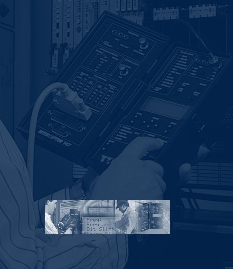
2 Installing and maintaining 2M and data circuits in the field requires the right tools. The INTERCEPTOR 147 Communications Analyser was specifically designed to meet this challenge by providing innovative and powerful testing features in an easy-to-use, rugged package. Complete 2M Testing and handheld convenience. The INTERCEPTOR 147 Communications Analyser offers a complete set of in-service and out-ofservice 2M tests and measurements to evaluate circuit performance and isolate problems. The inclusion of five standard data interfaces allows full span testing at subrate access points as well as a mux/demux mode which allows for wrapping around multiplexers and NTUs. Advanced network synchronisation and VF analysis add to the unit s versatility. Set-ups are simplified because the INTERCEPTOR 147 Communications Analyser automatically configures to the signal under test. Status indicators, result LEDs, and summary categories provide an instant view of instrument set-up and circuit activity, making problem isolation quick and easy. The powerful testing capabilities of the unit, combined with field ruggedness, and a weight of just 1.84 kg (4 pounds), make the INTERCEPTOR 147 Communications Analyser ideal for any field service situation. Highlights Supports Five Data Communications Interfaces V.11 (RS-449), V.24 (RS-232), V.35/306, X.21, and 64 kbps codirectional, to provide synchronous and asynchronous testing. Live 2M Testing Thoroughly test 2M, Nx64 kbps, and GSM 16 kbps subrate services. Insert monitor and test patterns on any selected timeslot without affecting live traffic. Test Subrate and Data Applications Enables synchronous and asynchronous testing and DTE and DCE emulation rates from 50 bps to 2M.

3 Reduce Set-up Time Auto-configuration instantly determines the framing and pattern, while the active TIMESLOTS display simplifies monitoring of channel call activity and loading. Qualify VF, Data, and CAS Monitor CAS signalling, data, and VF traffic using ABCD bit display, receive byte display, and built-in speaker. Synchronise Network Timing With Timing Analysis option, use standard pattern slip and frequency deviation measurements to diagnose faulty network timing. Test Switches and Cross-Connects Configure the transmitter and receiver for different timeslots when testing through switches and cross-connects. Long-Term Testing Remote control, automatic printing, and histogram capabilities allow unattended testing and long-term collection of data. Control Loopbacks Euro ISDN Loopcodes provides control of loopbacks in the NTE and LTE. Hand-Held Convenience Rugged and lightweight, ideal for the mobile technician. TTC s INTERCEPTOR 147 is a rugged field instrument.

4 Installing and Commissioning Full and Subrate 2M Service Installing and Commissioning Full and Subrate 2M Service. Thoroughly test 2M, Nx64 kbps, and GSM 16 kbps subrate services. Performance can be measured according to ITU-T recommendations G.821, G.826 and M Isolate problems resulting from timeslot delays, faulty line equipment, and misoptioned cross-connects, multiplexers and NTUs quickly and easily. Monitoring Live 2M Circuits Monitoring Live 2M Circuits. Monitoring live 2M circuits is simple with the INTERCEPTOR 147 Communications Analyser. Automatically determine the framing and pattern present on the circuit. The front panel LEDs immediately display the status of the line and show results at a glance. In-service measurements such as receive level, CRC errors, alarm status, receive frequency, timing slips (optional), and M.2100 analysis verify circuit quality without disrupting live traffic. ABCD bits can be monitored and voice timeslots can be dropped to the speaker to hear sound quality.

5 Isolating Network Synchronisation Problems Isolating Network Synchronisation Problems. When combined with the Timing Analysis option, the INTERCEPTOR 147 Communications Analyser easily detects synchronisation problems. Advanced measurements such as frame slip, bit slip, and received frequency allow quick identification of differential timing problems that cause buffer overflow and clock variations. Because the INTERCEPTOR Timing Analysis option allows for a large variable frequency offset (±20,000 ppm), network elements can be stress tested to isolate and correct marginal sources. Combined 2M and Data testing Combined 2M and Data testing. The addition of five data interfaces to the INTERCEPTOR 147 Communications Analyser enables it to test virtually anywhere in the 2M network. It can replace a DTE or DCE (such as a multiplexer, host computer, NTU or PBX), providing the flexibility to fully test the network in various configurations. Tests can be performed end-to-end, using loopbacks (LL, RL), using mux mode to wrap around a multiplexer, or in thru mode. This capability offers maximum flexibility to sectionalise and locate problems in- or out-of-service. Round trip delay is also measured to verify circuit routing and buffering. Qualify VF, Data, and CAS. Monitor CAS signalling data and VF traffic using ABCD bit display, receive byte display, and built-in speaker. Variable rate tone insertion and VF peak, level, and frequency measurements thoroughly test and verify transmission for fax and voice applications. Test Subrate and Data Applications. Enables synchronous and asynchronous testing and DTE and DCE emulation rates from 50 bps to 2M. For wrap-around testing of network components, mux/demux mode simultaneously tests from 2M and data interface access points. Signalling status indicator, lead control, and delay measurement make for a complete solution for testing at the DTE/DCE interface.


6 Timing Analysis Option With this option, the INTERCEPTOR 147 Communications Analyser becomes an indispensable tool for locating timing discrepancies between equipment and networks. Bit slip and Frame slip measurements differentiate between controlled and uncontrolled timing slippage. Transmit frequency offset stress tests to locate marginal components and the cause of network timing slips. Active Timeslot Display A glance at the screens shows traffic loading on all timeslots. The display distinguishes between idle and active timeslots and identifies FAS and MFAS framing. Mux Mode With mux mode, the INTERCEPTOR 147 Communications Analyser can be configured to transmit from a data interface and receive the signal at a 2M, or fractional (Nx64 or Nx56 kbps) service, or transmit from a 2M service and receive at a data interface. 2M Level Measurement M e a s u re the output level at 2M transmitters to isolate faulty equipment. Monitor the signal level at receivers to check for excessive cable attenuation. Broadcast Mode Test pattern or tone can be repeated on every timeslot with the INTERCEPTOR 147 Communications Analyser. This is particularly beneficial when used in conjunction with another Nx64 or data interface test instru m e n t. DTM Remote Control Extend the reach of experienced technicians by using the INTERCEPTOR 147 Communications Analyser as a remote test probe. DTM software enables any PC to remotely control multiple units.
7 Measurements Summary Bit Errors, Code Errors, FAS Errors, MFAS Errors, CRC Errors, Pattern Losses, Pattern Slips, Received Frequency Deviation (ppm) Logic and Time Receive Pattern, Bit Errors, Bit Error Rate, P a t t e rn Sync Losses, Pattern Slips, Elapsed Seconds, Test Seconds, Date, Time, Signal Lead Delay, Round Trip Delay, Character Errors (V.24 Async Only) Signal, Code, and Frame Received Fre q u e n c y, Receive Frequency Deviation (ppm), Received Level (db nom), Received Level (V peak), Code Errors, Code Error Rate, FAS Errors (Wo rd or Bit), FAS Error Rate (Wo rd or Bit) MFAS Errors, M FAS Error Rate, CRC-4 Errors, CRC-4 Error Rate, FAS Wo rd, NFAS Wo rd, MFAS Wo rd, CRC-4 Wo rd, REBE, Sa6 Bits, Bit Slip (timing analysis option), Frame Slip (timing analysis option) Channel and Signalling Active Timeslots, Received ABCD Signalling, Receive Byte, VF Fre q u e n c y, VF Peak Code, VF Signal Level [G.821, G.826 and M.2100 Performance Analysis] [Euro ISDN Loopcodes] [Euro ISDN Sa6 Message Display] 2M Specifications Operating Modes Framing: (ITU-T G.704) FAS, FAS-CRC, MFAS, MFAS-CRC, Unframed 2M Channel Access: 64 kbps, 56 kbps, 16 kbps timeslot access Contiguous or non-contiguous Nx64 or Nx56 kbps t i m e s l o t s Channel Associated Signalling Analysis: Display ABCD bits, Print signalling changes, I n s e rt ABCD bits Transmitter Clock Sources: I n t e rnal (±5 ppm) R e c o v e re d O ffset ±20,000 ppm in 1 ppm steps (timing analysis option) E x t e rnal (timing analysis option) E n c o d i n g : HDB3, AMI Output Connectors/Levels: 120 Ω balanced: (ITU-T G.703) 75 Ω unbalanced: 1.6/5.6 or BNC (ITU-T G.703) Serial 8-Pin DIN Generator Fixed Pattern s : Mark, Space, 1:1, 1:3, 1:4, Program, Byte Pseudorandom Pattern s : 2 6-1, 2 9-1, , , , Other Pattern s : QRSS, Delay To n e : Variable 300 Hz to 3000 Hz, and +3 db to -20 db Logic, FAS, Code Error Insert i o n : Single, 10-3, 5x10⁻³ rate Receiver Input Sensitivity: Te rminate - Cable Compensation: 0 db to -22 db Bridge - Cable Compensation: +6 db to -22 db Monitor - Resistive Attenuation: -18 db to -30 db Input Impedance: Te rminate or monitor: 120 Ω balanced 75 Ω unbalanced Bridge: >2000 Ω Indicators Signal, FAS Sync, MFAS Sync, Pattern Sync, Pattern Invert, CRC-4, AIS, TS-16 AIS, FAS Distant, MFAS Distant, P a t t e rn Slip, Octet Timing, Control Leads 2M Signal Analysis: F requency Measurement Range: 56 khz to MHz (±5 ppm) V F : Peak Code: -127 to +127 Channel Level: -60 to +3 dbm (±0.5 dbm) 2 M : Peak Voltage: 0 to 7 V (±3%) Level: -36 to 7.4 dbnom (±0.3 dbnom) Datacom Specifications V.11 (RS-449) Data Interface (Adapter cable required) Data Rates: Te rminated and Unterminated (RS-422/423): S y n c h ronous: 300 bps to Mbps Synthesised: 50 bps to Mbps in 1 bps steps (timing analysis option) R e c e i v e r s : Te rmination Resistance (specified with fail-safe networks): 100 Ω, > 7000 Ω for signalling Input Impedance: >5000 Ω (RCV DATA, RCV CLK, EXT TX CLK) Input Thre s h o l d : ±0.2 V (A vs. B) Loopback Support : Local (LL) and Remote (RL)
8 V.35/306 Data Interface (Adapter Cable Required) Data Rates: S y n c h ro n o u s : 300 bps to Mbps S y n t h e s i s e d : 50 bps to Mbps in 1 bps steps ( timing analyses O p t i o n ) Clock and Data To l e r a n c e s : D e l a y, SCT to SD: A p p roximately 70 ns typical S k e w, SCTE to SD: A p p roximately 20 ns typical Balanced Receivers: Load Resistance: 100 Ω Generator Impedance: Less then 100 Ω Loopback Support : Local (LL) and Remote (RL) X.21 Data interface 1 Data Rates: S y n c h ro n o u s : 300 bps to Mbps S y n t h e s i s e d : 50 bps to Mbps in 1 bps steps (timing analysis o p t i o n ) R e c e i v e r s : Te rmination Resistance (specified with fail-safe networks): 100 Ω, >5000 Ω for signalling Input Impedance: >8000 Ω (RCV DATA, RCV CLK, EXT TX CLK) 1 Physical Interface V.11 access only, does not provide X.21 call establishment pro c e d u re s. V.24 (RS-323) Data Interface Signal Form a t : B i p o l a r, unbalanced Timing Modes: A s y n c h ronous, Synchro n o u s Data Rates: A s y n c h ro n o u s : 300 bps to 19.2 kbps (in accordance with ITU-T V. 2 4 and EIA RS-232) S y n c h ro n o u s : 300 bps to 64 kbps (in accordance with ITU-T V.24 and EIA RS-232) S y n t h e s i s e d : 50 bps to Mbps in 1 bps steps (timing analysis option) Loopback Support : Local (LL) and Remote (RL) ITU-T G kbps Codirectional Interface (Adapter Cable Required) G e n e r a l : Transmit rate: 64 khz ± 5ppm Pulse Shapes: C o n f o rm to masks in CCITT Recommendation G.703 Pulse Level: 1.0 V ± 0.1 V Octet Code Form a t : A l t e rnate block inversion with bipolar violations for octet timing Input Impedance: Te rm : 120 Ω B r i d g e : 1000 Ω minimum Input Signal Level: +6 db to -9 db (in re f e rence to nominal signal level) Code format (256k baud): B i n a ry One: B i n a ry Zero : Pulse Wi d t h : Single Pulse: 3.9 µs Double Pulse: 7.8 µs General P rogram Storage: S t o re and recall up to 10 complete instrument configurations Non-volatile Memory : S t o re front-panel switch setting, entries, and a u x i l i a ry settings Remote Contro l : V.24 IEEE Syntax T T C s DTM remote control software capability Printer Controls Results Print: Time, date, results listing C o n t rols Print: Time, date, test configuration C o n n e c t o r : Serial 8-Pin DIN - 25-pin D Subminiature, adapter cable provided P r i n t o u t s : Timed, Event and Histogram Physical and Environmental Size: 9.1 cm (3.6 in) high, 11.4 cm ( 4.5 in) wide, 21.8 cm (8.6 in) deep Weight: 1.8 kg (4lbs.) Operating Te m p e r a t u re: 0 to 45 C (32 to 113 F) Storage Te m p e r a t u re : 40 to 70 C (-40 to 158 F) Power Requirements: 6.0 Watts maximum I n t e rnal Battery : Type: Sealed lead acid Operation: 3-6 hours (Depending on mode) C h a rging Time: 8 hours
9 Product Information Model No. Description Mbps and Data Analyser Includes: AC adapter, printer cable adapter Options Model No. Description Timing Analysis Option (includes±50, ±100 and ± 20,000 ppm Transmit Frequency Off s e t ) /5.6 Connectors Accessories Model No. Description P R 40 A V.24 Serial Printer Te c h n i c i a n s Soft Case L a rge Te c h n i c i a n s Case I A D P - E U AC Adapter for Europe I A D P - U K AC Adapter for United Kingdom I A D P - A U AC Adapter for Australia I A D P - U S AC Adapter for United States A variety of cables are also available. N O T E: Specifications, terms, and conditions are subject to change without notice. Copyright 1999, TTC, a division of Dynatech, LLC. All rights re s e rved. TTC and INTERCEPTOR are re g i s t e red trademarks of TTC, a division of Dynatech, LLC. All other trademarks and re g i s t e red trademarks are the pro p e rty of their respective companies.
10
2 Mbit/s and Data Analyzer. Reference Manual
 50-13139-01 Rev. B TM 2 Mbit/s and Data Analyzer Reference Manual APRIL 1995 1992 Telecommunications Techniques Corporation 20400 Observation Drive, Germantown, Maryland 20876 (800) 638-2049 or (301) 353-1550
ProBER 2 2 Mb/s Handheld Test Set. The handheld that takes 2 Mb/s testing beyond convention
 ProBER 2 2 Mb/s Handheld Test Set The handheld that takes 2 Mb/s testing beyond convention 1 2 Mb/s BER and signal quality measurements in a handheld The ProBER 2 test set provides a powerful handheld
AccessCON-N64 INTERFACE CONVERTER E1/FRACTIONAL E1 TO N64 INSTALLATION AND OPERATION MANUAL. Version 1
 INTERFACE CONVERTER E1/FRACTIONAL E1 TO N64 INSTALLATION AND OPERATION MANUAL Version 1 Copyright 2005 by S-Access GmbH. The contents of this publication may not be reproduced in any part or as a whole,
Advanced Test Equipment Rentals ATEC (2832)
") Established 1981 Advanced Test Equipment Rentals www.atecorp.com 800-404-ATEC (2832) 50-15217-01 Rev. D T-BERD 2207 USER S GUIDE This manual applies to all T-BERD 2207 software incorporating software level
Established 1981 Advanced Test Equipment Rentals www.atecorp.com 800-404-ATEC (2832) 50-15217-01 Rev. D T-BERD 2207 USER S GUIDE This manual applies to all T-BERD 2207 software incorporating software level
G7104A Multimaster Base Station Tester
 COMMUNICATIONS TEST & MEASUREMENT SOLUTIONS G7104A Multimaster Base Station Tester Key features Multi-function integration The Multimaster has integrated all necessary functions to test and measure CDMA
Atrie WireSpan 600/610 MODEM User's Manual
 Atrie WireSpan 600/610 MODEM User's Manual WireSpan 600 / 610 Fractional E1 Access Unit Installation and Operation manual CONTENTS CHAPTER 1 Interduction.. 1-1 CHAPTER 2 Installation and Setup.. 2-1 CHAPTER
Advanced Test Equipment Rentals ATEC (2832) T-BERD 209A/211. Dual Results Display. Alarm Indicators.
 T-BERD 209A/211. Dual Results Display. Alarm Indicators.") Established 1981 Advanced Test Equipment Rentals www.atecorp.com 800-404-ATEC (2832) Dual Results Display Restart Alarm Indicators Signal Loss Yellow Alarm Pattern Loss All Ones Frame Loss Pulse Shape
Established 1981 Advanced Test Equipment Rentals www.atecorp.com 800-404-ATEC (2832) Dual Results Display Restart Alarm Indicators Signal Loss Yellow Alarm Pattern Loss All Ones Frame Loss Pulse Shape
Telecommunications. 2842/43 Digital Communications Analyzer.
 Telecommunications 2842/43 Digital Communications Analyzer Hand-held, high capability testing for 2 Mbit/s and data line systems and equipment Handheld, battery operated, data and PCM rate tester Framed
Telecommunications. 2852/S & 2853/S Digital Analyzers.
 Telecommunications 2852/S & 2853/S Digital Analyzers Desktop and rackmountable digital testers for PCM and data applications up to including mux/demux PCM and data pattern generator and error detector
MultiMaster. Base Station Test Tools. Multi Purpose Base Station Tester. Introduction. Feature
 Introduction The GenComm is a comprehensive and cost effective solution for performing base station and repeater maintenance in any environment covering all CDMA Standards including cdmaone, cdma2000 1x
Modem E1. Modem-converter E1-L. Features. Contents
 Modem-converter E1-L User s Guide 1234567890123456789012345678901212345678901234567890123456789012123456789012345678901234567890121234567 Modem E1 Features E1 G703/G704 channel Distance up to 1.5 km V.35/RS-530/RS-449/RS-232/X.21/
Advanced Test Equipment Rentals ATEC (2832) T-Carrier Analyzer
 T-Carrier Analyzer") Established 1981 Advanced Test Equipment Rentals www.atecorp.com 800-404-ATEC (2832) T-BERD 209A/211 T-Carrier Analyzer RELIABLE. RUGGED. EASY TO USE. Introduction For over a decade, telecom technicians
Established 1981 Advanced Test Equipment Rentals www.atecorp.com 800-404-ATEC (2832) T-BERD 209A/211 T-Carrier Analyzer RELIABLE. RUGGED. EASY TO USE. Introduction For over a decade, telecom technicians
DIGITAL LINK MEASURING INSTRUMENTS MS371A/A1 GPIB PCM CHANNEL ANALYZER. For Simultaneous Measurement of 30 Channels with MS120A
 PCM CHANNEL ANALYZER MS371A/A1 For Simultaneous Measurement of 30 Channels with MS120A (MS371A1) GPIB The MS371A/A1 is an overall measuring instrument with many measuring functions for digital primary
Interface converter G kbit/sec
 converter User s Guide 12345678901234567890123456789012123456789012345678901234567890121234567890123456789012345678901212345678901 Interface converter G.703.1 64 kbit/sec Features Maximum line attenuation
Complimentary Reference Material
 Complimentary Reference Material This PDF has been made available as a complimentary service for you to assist in evaluating this model for your testing requirements. TMG offers a wide range of test equipment
NETWORK. TE = Terminal Equipment (DTE - Data Terminal Equipment) NT = Network - Terminating Equipment (DCE - Data Circuit - Terminating Equipment)
 NT = Network - Terminating Equipment (DCE - Data Circuit - Terminating Equipment)") NETWORK INTERFACING TE NT NETWORK NT TE Interface Interface TE = Terminal Equipment (DTE - Data Terminal Equipment) NT = Network - Terminating Equipment (DCE - Data Circuit - Terminating Equipment) Interface
NETWORK INTERFACING TE NT NETWORK NT TE Interface Interface TE = Terminal Equipment (DTE - Data Terminal Equipment) NT = Network - Terminating Equipment (DCE - Data Circuit - Terminating Equipment) Interface
Concept of Serial Communication
 Concept of Serial Communication Agenda Serial v.s. Parallel Simplex, Half Duplex, Full Duplex Communication RS-485 Advantage over RS-232 Serial v.s. Parallel Application: How to Measure the temperature
VC-4/4A, VC-8/8A, VC-16 4/8/16-Channel PCM and ADPCM Voice Modules
 4, 8 or 16 analog voice channels using 64 kbps toll-quality PCM encoding; 24/32 kbps ADPCM encoding option for 4- and 8-channel modules E&M, FXS or FXO interface options Caller ID A-law or μ-law companding
Firmware upgrades with new features are freely available and can be easily downloaded to the LT51 in the field.
 LINE TESTER LT51 The LT51 Line Tester is a portable handheld battery powered instrument. It combines the features of several pieces of test equipment such as a Selective Level Meter / Spectrum Analyser,
Installation and Operation Manual HS-R. 4-Channel Low Speed Data Module with V.110 Rate Adaptation MEGAPLEX-2100 MODULE
 Installation and Operation Manual HS-R 4-Channel Low Speed Data Module with V110 Rate Adaptation MEGAPLEX-2100 MODULE MEGAPLEX-2100 MODULE HS-R 4-Channel Low Speed Data Module with V110 Rate Adaptation
ANALOG AND DIGITAL PHYSICAL INTERFACES
 ANALOG AND DIGITAL PHYSICAL INTERFACES Habib Youssef, Ph.D youssef@ccse.kfupm.edu.sa Department of Computer Engineering King Fahd University of Petroleum and Minerals Dhahran, Saudi Arabia COMPUTER NETWORK
PHYSICAL/ELECTRICAL CHARACTERISTICS OF HIERARCHICAL DIGITAL INTERFACES. (Geneva, 1972; further amended)
") 5i Recommendation G.703 PHYSICAL/ELECTRICAL CHARACTERISTICS OF HIERARCHICAL DIGITAL INTERFACES (Geneva, 1972; further amended) The CCITT, considering that interface specifications are necessary to enable
5i Recommendation G.703 PHYSICAL/ELECTRICAL CHARACTERISTICS OF HIERARCHICAL DIGITAL INTERFACES (Geneva, 1972; further amended) The CCITT, considering that interface specifications are necessary to enable
Interface: Serial EIA RS-232D/CCITT V.24, DCE; RTS/CTS delay 0,8 or 64 ms (user-selectable).
.") BLACK BOX PWR RTS TD-1 RD-1 TD-2 DCD RD-2 TEST DIG ANA REM LDM-MR 19.2 REM ANA DIG AGC 2/4 WIRE ABLE / ABLE SWITCHES 2 W 4 W 1 2 3 4 CARRIER LEVEL 0 dbm -3 dbm -6 dbm -9 dbm PIN 21 (RLB) RPF PIN 18 AN.
BLACK BOX PWR RTS TD-1 RD-1 TD-2 DCD RD-2 TEST DIG ANA REM LDM-MR 19.2 REM ANA DIG AGC 2/4 WIRE ABLE / ABLE SWITCHES 2 W 4 W 1 2 3 4 CARRIER LEVEL 0 dbm -3 dbm -6 dbm -9 dbm PIN 21 (RLB) RPF PIN 18 AN.
khz to 2.9 GHz Spectrum Analyzer
 Spectrum Analyzers 2399 9 khz to 2.9 GHz Spectrum Analyzer A spectrum analyzer with outstanding performance and a user friendly visual interface simplifying many complex measurements. 9 khz to 2.9 GHz
Multiplexer - Voice Transcoder E1-XLC
 E1-XLC Multiplexer User s Guide 12345678901234567890123456789012123456789012345678901234567890121234567890123456789012345678901212345678901 Multiplexer - Voice Transcoder E1-XLC Features Desktop or the
USER MANUAL G703FTEC. T1/E1 Cross Rate Converter
 USER MANUAL G703FTEC T1/E1 Cross Rate Converter CTC Union Technologies Co., Ltd. Far Eastern ViennaTechnology Center (Neihu Technology Park) 8F, No. 60 Zhouzi St. Neihu Taipei 114, Taiwan G703-FTEC T1/E1
This manual may be copied in any form including electronic. It may not be modified in any way without the express permission of CTC Union
 USER S GUIDE This manual may be copied in any form including electronic. It may not be modified in any way without the express permission of CTC Union Technologies Co. Ltd. Description G703/64A I/F Converter
INTERNATIONAL TELECOMMUNICATION UNION
 INTERNATIONAL TELECOMMUNICATION UNION CCITT G.703 THE INTERNATIONAL TELEGRAPH AND TELEPHONE CONSULTATIVE COMMITTEE (11/1988) SERIE G: TRANSMISSION SYSTEMS AND MEDIA, DIGITAL SYSTEMS AND NETWORKS General
Sage Instruments 935AT. Test Options Guide
 Sage Instruments 935AT Test Options Guide Last Updated 20 February 2001 Table of Contents 935AT Applications... 3 Transmission... 3 Signaling and Supervision... 3 Trunks... 3 Digits... 3 Emulation... 3
2026Q CDMA/GSM Interferer MultiSource Generator
 Signal Sources 2026Q CDMA/GSM Interferer MultiSource Generator The 2026Q is designed to work with a radio test set to provide a fully integrated radio receiver test solution for cellular and PCS systems
Chapter 12: Digital Modulation and Modems
 Chapter 12: Digital Modulation and Modems MULTIPLE CHOICE 1. FSK stands for: a. Full-Shift Keying c. Full-Signal Keying b. Frequency-Shift Keying d. none of the above 2. PSK stands for: a. Pulse-Signal
High-speed programmable attenuator MAT800
 High-speed programmable attenuator MAT800 Windows98/Me/2000/XP/Vista/7(32bit) correspondence GP-IB, RS-232C and software for making attenuation program are standard accessories. Optimum for evaluation
World s Most Trusted Family of Handheld RF and Microwave Analyzers
 World s Most Trusted Family of Handheld RF and Microwave Analyzers Introducing applications specific solutions for the RF and Microwave field testing industry Site Master Site Master s seven models of
INSTALLATION and OPERATION MANUAL
 INSTALLATI and OPERATI MANUAL CTC Union Technologies Co., Ltd. Far Eastern Edison Science and Technology Center 6F-3, No. 15, Lane 360 NeiHu Rd., Section 1 NeiHu, Taipei, 114 Taiwan G703 Pack Series G.703
) #(2/./53 $!4! 42!.3-)33)/.!4! $!4! 3)'.!,,).' 2!4% ()'(%2 4(!. KBITS 53).' K(Z '2/50 "!.$ #)2#5)43
 #(2/./53 $!4! 42!.3-)33)/.!4! $!4! 3)'.!,,).' 2!4% ()'(%2 4(!. KBITS 53).' K(Z '2/50 !.$ #)2#5)43") INTERNATIONAL TELECOMMUNICATION UNION )454 6 TELECOMMUNICATION STANDARDIZATION SECTOR OF ITU $!4! #/--5.)#!4)/. /6%2 4(% 4%,%(/.%.%47/2+ 39.#(2/./53 $!4! 42!.3-)33)/.!4! $!4! 3)'.!,,).' 2!4% ()'(%2 4(!.
INTERNATIONAL TELECOMMUNICATION UNION )454 6 TELECOMMUNICATION STANDARDIZATION SECTOR OF ITU $!4! #/--5.)#!4)/. /6%2 4(% 4%,%(/.%.%47/2+ 39.#(2/./53 $!4! 42!.3-)33)/.!4! $!4! 3)'.!,,).' 2!4% ()'(%2 4(!.
Part IV: Glossary of Terms
 Issue 9 November 2004 Spectrum Management and Telecommunications Policy Compliance Specification for Terminal Equipment, Terminal Systems, Network Protection Devices, Connection Arrangements and Hearing
USER MANUAL ETU02-MUX 2/4 Port G.703 E1 Multiplexer with SNMP
 USER MANUAL ETU02-MUX 2/4 Port G.703 E1 Multiplexer with SNMP CTC Union Technologies Co., LEGAL The information in this publication has been carefully checked and is believed to be entirely accurate at
VCL-LD TM O T N RION ELECOM ETWORKS INC. VCL-LD E1, DCME. Voice Compression Equipment. Product Specifications
 O T N RION ELECOM ETWORKS INC. TM, DCME (Digital Circuit Multiplication Equipment) Voice Compression Equipment Product Specifications Headquarters: Phoenix, Arizona Orion Telecom Networks Inc. 20100, N
DG5000 series Waveform Generators
 DG5000 series Waveform Generators DG5000 is a multifunctional generator that combines many functions in one, including Function Generator, Arbitrary Waveform Generator, IQ Baseband /IQ IF, Frequency Hopping
E1UC - Portable E1 USB Data Capture
 - Portable E1 USB Data Capture Real-time capture, routing and grooming of E1/PRI (G.703/G.704) 2,048 Kbits/s bitstreams. provides real-time interfacing to E1, PRI and G.703 signal systems on a PC via USB.
Spectrum Analyzers. 2394A 1 khz to 13.2 GHz Spectrum Analyzer.
 Spectrum Analyzers 2394A 1 khz to 13.2 GHz Spectrum Analyzer A spectrum analyzer with outstanding performance and a user friendly visual interface simplifying many complex measurements 1 khz to 13.2 GHz
DS 6000 Specifications
 DS 6000 Specifications All the specifications are guaranteed except the parameters marked with Typical and the oscilloscope needs to operate for more than 30 minutes under the specified operation temperature.
Part VI: Requirements for Integrated Services Digital Network Terminal Equipment
 Issue 9, Amendment 1 September 2012 Spectrum Management and Telecommunications Compliance Specification for Terminal Equipment, Terminal Systems, Network Protection Devices, Connection Arrangements and
Digital Microwave Radios
 CM Digital Microwave Radios Operating at 6, 7, 8 & 11 GHz With Capacities of 4, 8, 16E1 E3, STM-1 & 2x100BaseT The CM offers bandwidth efficient long haul data transmission for common carrier, cellular
The DR-2000 is a high-performance receiver designed to enable highly sophisticated data and signal processing over a wide frequency spectrum.
 The DR-2000 is a high-performance receiver designed to enable highly sophisticated data and signal processing over a wide frequency spectrum. L3 (L3 T&RF) DR-2000 receiving unit incorporates a high-performance
GPS10RBN-26: 10 MHz, GPS Disciplined, Ultra Low Noise Rubidium Frequency Standard
 GPS10RBN-26: 10 MHz, GPS Disciplined, Ultra Low Noise Rubidium Standard Key Features Completely self-contained unit. No extra P.C needed. Full information available via LCD. Rubidium Oscillator locked
Agilent 8657A/8657B Signal Generators
 Agilent / Signal Generators Profile Spectral performance for general-purpose test Overview The Agilent Technologies and signal generators are designed to test AM, FM, and pulsed receivers as well as components.
PHYTER 100 Base-TX Reference Clock Jitter Tolerance
 PHYTER 100 Base-TX Reference Clock Jitter Tolerance 1.0 Introduction The use of a reference clock that is less stable than those directly driven from an oscillator may be required for some applications.
PT 5879 MIP INSERTER AGS*/MIP. ransmitter. TRX ID TAG data. TRX ID TAG data. TRX ID TAG data. TRX ID TAG data. data Reset Count Timing
 PT 5879 MIP INSERTER *supports pro any existing Carousel management ransmitter 1 PPS 10 MHz AGS*/MIP G-2 TS. MIP 0 0 0 0 0 0 0 0 control DVB-T Modulation (SFN) DVB Chan I NTRODUCTION The Single Frequency
Quick Site Testing with the 8800SX
 Quick Site Testing with the 8800SX Site Testing with the 8800SX Basic Tests 5 site testing involves several tests to verify site operation. NOTE: This is not intended to be a complete commissioning procedure.
A-MUX 32P DOCUMENTATION
 A-MUX 32P DOCUMENTATION CONTENTS 1. General description 2 2. Applications 3 3. A-MUX specifications 5 4. Connectors of E1 and Ethernet interface 7 5. Connectors of analog interfaces 8 6. Modules FXS, FXO,
Appendix A. Datum Systems PSM-2100/512 Satellite Modem. Technical Specification
 Appendix A Datum Systems PSM-2100/512 Satellite Modem Technical Specification PSM-2100 and PSM-512 VSAT / SCPC - Modem Specification Revision History Rev 1.0 6-15-97 Preliminary Release. Rev 1.1 10-10-97
SIGNAL GENERATORS. MG3633A 10 khz to 2700 MHz SYNTHESIZED SIGNAL GENERATOR GPIB
 SYNTHESIZED SIGNAL GENERATOR MG3633A GPIB For Evaluating of Quasi-Microwaves and Measuring High-Performance Receivers The MG3633A has excellent resolution, switching speed, signal purity, and a high output
XR-T6165 Codirectional Digital Data Processor
 ...the analog plus company TM XR-T6165 Codirectional Digital Data Processor FEATURES APPLICATIONS Dec 2010 Low Power CMOS Technology All Receiver and Transmitter Inputs and Outputs are TTL Compatible Transmitter
Signal Forge. Signal Forge 1000 TM Synthesized Signal Generator. Flexible Design Enables Testing of RF and Clock-driven Systems.
 Signal Forge TM Signal Forge 1000 TM Synthesized Signal Generator L 8.5 W 5.4 H 1.5 Flexible Design Enables Testing of RF and Clock-driven Systems The Signal Forge 1000 combines a 1 GHz frequency range
Part VI: Requirements for ISDN Terminal Equipment
 Issue 9 November 2004 Spectrum Management and Telecommunications Policy Compliance Specification for Terminal Equipment, Terminal Systems, Network Protection Devices, Connection Arrangements and Hearing
Kilomux-2100/2104 KVF.4 2-Channel Low Bit Rate Voice/Fax Module
 Data Sheet Kilomux-2100/2104 KVF.4 High quality voice at 4.8, 6.4, 7.2, 9.6 or 12.8 kbps Fax Group III support with automatic rate fallback Double compression (tandeming) Transfers modem data relay at
DSP4xxFP SA USER S MANUAL. A01561 Rev. A. This Manual covers all configurations of the DSP4xxSA Modem with the Serial Number SA and up.
 DSP4xxFP SA USER S MANUAL A01561 Rev. A This Manual covers all configurations of the DSP4xxSA Modem with the Serial Number SA700425 and up. DSP4xxSA User s Manual A01561 Rev. X Proprietary Data This document
WaveStation Function/Arbitrary Waveform Generators
 Function/Arbitrary Waveform Generators Key Features High performance with 14-bit waveform generation, up to 500 MS/s sample rate and up to 512 kpts memory 2 channels on all models Large color display for
Dual Protocol Transceivers Ease the Design of Industrial Interfaces
 Dual Protocol Transceivers Ease the Design of Industrial Interfaces Introduction The trend in industrial PC designs towards smaller form factors and more communication versatility is driving the development
R&S NRP-Zxx Power Sensors Specifications
 R&S NRP-Zxx Power Sensors Specifications year Data Sheet Version 11.00 CONTENTS Definitions... 3 Overview of the R&S NRP-Zxx power sensors... 4 Specifications in brief of the R&S NRP-Zxx power sensors...
F290X / F293X FOM II Series Fiber Optic Isolator Technical Manual
 F290X / F293X FOM II Series Fiber Optic Isolator Technical Manual Revision G Copyright 2017 VERSITRON, Inc. 83 Albe Drive / Suite C Newark, DE 19702 www.versitron.com E031130243 PROPRIETARY DATA All data
Agilent 8902A Measuring Receiver
 Agilent 8902A Measuring Receiver Technical Specifications Agilent 11722A Sensor Module Agilent 11792A Sensor Module Agilent 11793A Microwave Converter Agilent 11812A Verification Kit The Agilent Technologies
TC-3000C Bluetooth Tester
 TC-3000C Bluetooth Tester Product Instructions TC-3000C Bluetooth Tester is able to analyze the data of every packet that is transmitted to the upper application protocol layer using the protocol stack,
Acterna T-BERD Outside Plant Tester (209OSP) Simplifying test procedures with one complete solution
 Simplifying test procedures with one complete solution") Established 1981 Advanced Test Equipment Rentals www.atecorp.com 800-404-ATEC (2832) Acterna (209OSP) Simplifying test procedures with one complete solution Outside plant technicians have to perform a
Established 1981 Advanced Test Equipment Rentals www.atecorp.com 800-404-ATEC (2832) Acterna (209OSP) Simplifying test procedures with one complete solution Outside plant technicians have to perform a
khz to 2.7 GHz Spectrum Analyzer
 Spectrum Analyzers 2398 9 khz to 2.7 GHz Spectrum Analyzer A breakthrough in high performance spectrum analysis, combining cost effectiveness and portability in a new lightweight instrument 9 khz to 2.7
Appendix C T1 Overview
 Appendix C T Overview GENERAL T refers to the primary digital telephone carrier system used in North America. T is one line type of the PCM T-carrier hierarchy listed in Table C-. T describes the cabling,
The HC-5560 Digital Line Transcoder
 TM The HC-5560 Digital Line Transcoder Application Note January 1997 AN573.l Introduction The Intersil HC-5560 digital line transcoder provides mode selectable, pseudo ternary line coding and decoding
AFG-2100/2000 Series Arbitrary Function Generator. New Product Announcement
 AFG-2100/2000 Series Arbitrary Function Generator New Product Announcement The AFG-2100/2000 Series Arbitrary Function Generator The AFG-2100/2000 Series Arbitrary Function Generator is a DDS (Direct Digital
CDMA Principle and Measurement
 CDMA Principle and Measurement Concepts of CDMA CDMA Key Technologies CDMA Air Interface CDMA Measurement Basic Agilent Restricted Page 1 Cellular Access Methods Power Time Power Time FDMA Frequency Power
TCG 02-G FULL FEATURED SATELLITE CLOCK KEY FEATURES SUPPORTS
 FULL FEATURED SATELLITE CLOCK TCG 02-G The TCG 02-G is a highly accurate, full featured GPS and GLONASS (GNSS) clock. Offering multiple oscillator options, Time Code and Frequency outputs, it fits virtually
Interface Description Peak MTT
 Y-SC-06.60 4.0 2011-03-08 Håkan Sandström Interface Description Peak MTT Author: Håkan Sandström Approved by: Joakim Andersson Distribution List: form-04.05-1.1 2005-01-25 [STL 6] Page 1 (13) Contents
SIGNAL RECOVERY. Model 7265 DSP Lock-in Amplifier
 Model 7265 DSP Lock-in Amplifier FEATURES 0.001 Hz to 250 khz operation Voltage and current mode inputs Direct digital demodulation without down-conversion 10 µs to 100 ks output time constants Quartz
2.9GHz SPECTRUM ANALYZER
 2.9GHz SPECTRUM ANALYZER Introducing a new 2.9GHz Spectrum Analyzer Manufacturing Research and Development Field Service Education Powerful capacity by advanced digital synthesizer Revolutionary features
MEGAPLEX-2100 MODULE VC-16A. 16-Channel PCM/ADPCM Voice Module Installation and Operation Manual. Notice
 MEGAPLEX-2100 MODULE VC-1A 1-Channel PCM/ADPCM Voice Module Installation and Operation Manual Notice This manual contains information that is proprietary to RAD Data Communications No part of this publication
BASIC PARAMETERS FOR THE MEASUREMENT OF ERROR PERFORMANCE AT BIT RATES BELOW THE PRIMARY RATE
 INTERNATIONAL TELECOMMUNICATION UNION CCITT O.153 THE INTERNATIONAL TELEGRAPH AND TELEPHONE CONSULTATIVE COMMITTEE (11/1988) SERIES O: SPECIFICATIONS FOR MEASURING EQUIPMENT Equipment for the measurement
Power supply IA Ordinary current ID operation Input *1 I IL V I = 0 V leakage current I IH V I = V D
 Data Pack H Issued March 1997 232-2756 Data Sheet Modem IC 6929 CCITT V21 data format RS stock number 630-976 The 6926 is 300 bit per second chip modem designed to transmit and receive serial binary data
VC-4/4A, VC-8/8A, VC-16
 Data Sheet Megaplex-4, Megaplex-2100/2104 VC-4/4A, VC-8/8A, VC-16 E&M, FXS or FXO options Caller ID A-law or µ-law companding Optional inband signaling with A-law encoded channels PCM (64 kbps) and ADPCM
MODES AND PROTOCOL HANDLING
 A R T A D V A N C E D R A D I O T E C H N O L O G I E S R A D I O M O D E M S E R I E S The State of the Art ART Series was designed as a result of extensive market research. The product will therefore
M9606. FSK Modem. 5C Communications Inc.
 FSK Modem Application modem is a voice-frequency telegraphy unit (VFT unit) which operates according to the principle of binary frequency shift keying. It is designed especially for Power Industrial applications.
RECOMMENDATION ITU-R BT.1302 *
 Rec. ITU-R BT.1302 1 RECOMMENDATION ITU-R BT.1302 * Interfaces for digital component video signals in 525-line and 625-line television systems operating at the 4:2:2 level of Recommendation ITU-R BT.601
Troubleshooting E1 Lines with the NetTek YBT1E1 Circuit Tester
 Troubleshooting E1 Lines with the NetTek YBT1E1 Circuit Tester This application note addresses the most common measurement challenges faced by technicians who maintain base transceiver stations wireline
+3.3V Multiprotocol 3Tx/3Rx Software-Selectable Control Transceivers
 19-173; Rev 1; 8/1 +3.3V Multiprotocol 3Tx/3Rx General Description The are three-driver/three-receiver multiprotocol transceivers that operate from a single +3.3V supply. The, along with the MAX317 and
King Fahd University of Petroleum & Minerals Computer Engineering Dept
 King Fahd University of Petroleum & Minerals Computer Engineering Dept COE 342 Data and Computer Communications Term 021 Dr. Ashraf S. Hasan Mahmoud Rm 22-144 Ext. 1724 Email: ashraf@ccse.kfupm.edu.sa
SWT 3000 Teleprotection technical data siemens.com
 Power network telecommunication SWT 3000 Teleprotection technical data siemens.com Sustainable success for high-voltage power networks The SWT 3000 Teleprotection system has been the first choice for reliable
ST600 TRANSMITTER OPERATING INSTRUCTIONS
 ST600 TRANSMITTER OPERATING INSTRUCTIONS 1892 1273 These operating instructions are intended to provide the user with sufficient information to install and operate the unit correctly. The Wood and Douglas
Compliance Requirements Overview 1
 Compliance Requirements Overview T1 is a digital transmission link with a total transmit and receive rate of 1.544 Mbps (1544000 bits per second). E1 is a digital transmission link with a total transmit
USER'S MANUAL. Model : K
 USER'S MANUAL Model : 2000-64K TM GINA MODEL 2000-64K Overview GINA Model 2000-64K is a stand-alone, high frequency data transceiver using spread spectrum technology. GINA 2000-64K capabilities include
Signal Sources. 2026Q CDMA Interferer Multisource Generator. Advanced Test Equipment Rentals ATEC (2832)
") Signal Sources Established 1981 Advanced Test Equipment Rentals www.atecorp.com 800-404-ATEC (2832) 2026Q CDMA Interferer Multisource Generator The 2026Q is designed to work with a radio test set to provide
Signal Sources Established 1981 Advanced Test Equipment Rentals www.atecorp.com 800-404-ATEC (2832) 2026Q CDMA Interferer Multisource Generator The 2026Q is designed to work with a radio test set to provide
JD723A/JD724B/JD726A Cable and Antenna Analyzers
 COMMUNICATIONS TEST & MEASUREMENT SOLUTIONS JD723A/JD724B/JD726A Cable and Antenna Analyzers Key Features Portable and lightweight handheld instrument. Built in wireless frequency bands as well as the
TSA 6000 System Features Summary
 2006-03-01 1. TSA 6000 Introduction... 2 1.1 TSA 6000 Overview... 2 1.2 TSA 6000 Base System... 2 1.3 TSA 6000 Software Options... 2 1.4 TSA 6000 Hardware Options... 2 2. TSA 6000 Hardware... 3 2.1 Signal
AFG-2100/2000 Series Arbitrary Function Generator. New Product Announcement
 AFG-2100/2000 Series Arbitrary Function Generator New Product Announcement The AFG-2100/2000 Series Arbitrary Function Generator The AFG-2100/2000 Series Arbitrary Function Generator is a DDS (Direct Digital
WaveStation Function/Arbitrary Waveform Generators
 WaveStation Function/Arbitrary Waveform Generators Key Features High performance with 14-bit, 125 MS/s and 16 kpts 2 channels on all models Large 3.5 color display for easy waveform preview Over 40 built-in
DDS-PLL SYNTHESIZER DPL-2.5GF USER S MANUAL DIGITAL SIGNAL TECHNOLOGY, INC.
 DDS-PLL SYNTHESIZER DPL-2.5GF USER S MANUAL DIGITAL SIGNAL TECHNOLOGY, INC. 1-7-3, HIGASHI BENZAI, ASAKA CITY SAITAMA 351-22 JAPAN TEL : 81-48-468-694 FAX : 81-48-468-621 http://www.dst.co.jp/en 1 DPL-2.5GF
ROM/UDF CPU I/O I/O I/O RAM
 DATA BUSSES INTRODUCTION The avionics systems on aircraft frequently contain general purpose computer components which perform certain processing functions, then relay this information to other systems.
APPLICATION BULLETIN. SERIAL BACKGROUNDER (Serial 101) AB23-1. ICS ICS ELECTRONICS division of Systems West Inc. INTRODUCTION CHAPTER 2 - DATA FORMAT
 AB23-1. ICS ICS ELECTRONICS division of Systems West Inc. INTRODUCTION CHAPTER 2 - DATA FORMAT") ICS ICS ELECTRONICS division of Systems West Inc. AB- APPLICATION BULLETIN SERIAL BACKGROUNDER (Serial 0) INTRODUCTION Serial data communication is the most common means of transmitting data from one point
ICS ICS ELECTRONICS division of Systems West Inc. AB- APPLICATION BULLETIN SERIAL BACKGROUNDER (Serial 0) INTRODUCTION Serial data communication is the most common means of transmitting data from one point
WaveStation Function/Arbitrary Waveform Generators
 WaveStation Function/Arbitrary Waveform Generators Key Features High performance with 14-bit, 125 MS/s and 16 kpts 2 channels on all models Large 3.5 color display for easy waveform preview Over 40 built-in
Lynx. RoIP Gateway DISPATCH LYNX MOBILE. Optional serial ports provide remote control of radio configuration over the VoIP network.
 LYNX MOBILE Lynx DISPATCH RoIP TM SYSTEM Gateway LYNX TM ROIP GATEWAY OVERVIEW The Lynx system provides Radio over IP (RoIP) communications interoperability between radio base stations and VoIP networked
Ku-Band VSAT Block Up Converters
 FEATURES Single box BUC output power levels to 10W RS485 M&C capability Accurate RF Power Monitoring Maintenance Free Operation +24VDC or +48 VDC input voltage OPTIONS 10W L-Band to Ku-Band Block Up Converter