LEAD FREE CHIP RESISTOR SPECIFICATION
|
|
|
- Pauline Powers
- 6 years ago
- Views:
Transcription
1 ASJ PTE LTD LEAD FREE CHIP RESISTOR Reference No. : SYS-ENG-205 Revision No. : Z
2 DOC NO: SYS-ENG-205 PAGE: 2 of SCOPE PART NUMBERING SYSTEM RATING Rating Power Power Derating Characteristic Standard Atmospheric Condition Operating Temperature Range Storage Temperature Range Flammability Rating Moisture Sensitivity Rating Level Product Assurance RoHS Compliance Resistance Range, Resistance Tolerance & Temperature Coefficient of Resistance Rated Voltage MARKING ON PRODUCT Numeric Numbering DIMENSIONS, CONSTRUCTION AND MATERIALS Dimensions Zero ohm Construction Resistor Construction Materials ELECTRICAL CHARACTERISTICS AND TEST CONDITIONS Frequency Response Soldering Profile Flow Soldering Reflow Soldering TAPING Structure of Taping Materials Leader and Trailer Tape Position of Taped Component Dimension Performance of Taping Strength of Carrier tape and top cover tape Peel force of top cover tape Minimum Bending Radius Number of missing components and mistake in taping Packaging Taping Identification Packaging Reel Box Reel Dimensions Bulk Cassette Packaging Surface Mount Land Patterns Applicable Standards
3 DOC NO: SYS-ENG-205 PAGE: 3 of SCOPE 1.1. This specification specifies fixed thick film chip resistor (referred to as resistor hereinafter) for use in electronic equipment. In case there are discrepancies in specifications between this specification and the Customer s specifications, the latter shall precede. 2. PART NUMBERING SYSTEM Part Numbering is made in accordance with the following system: CRXX - XXXX - X X Resistance Resistance Value Tolerance Packaging CR D - 0.5% L - 5K reel CR F - 1% K - 10K reel CR G - 2% E - 4K reel CR J - 5% Y - 20K reel CR K - 10% CR M - 20% CR Z Zero ohm CR RATING 3.1. Rated Power Zero Ohm Jumper Rated Power Rated Current Maximum Working Current Maximum Overload Current Dielectric Withstanding Voltage Resistance Tolerance CR05 0.5A 0.5A 2A 300V < 50m Ω CR10 1A 1A 2.5A 300V < 50m Ω CR16 2A 2A 5A 300V < 50m Ω CR21 2A 2A 5A 500V < 50m Ω CR32 2A 2A 5A 500V < 50m Ω CR40 2A 2A 5A 500V < 50m Ω CR50 2A 2A 5A 500V < 50m Ω CR63 3A 3A 15A 500V < 50m Ω Resistor Rated Power Rated Power Maximum Working Voltage Maximum Overload Voltage Maximum Intermittent Overload Voltage Dielectric Withstanding Voltage CR05 1/20W 15V 50V 50V 50V CR10 1/16W 50V 100V 100V 300V CR16 1/10W 50V 100V 100V 300V CR21 1/8W 150V 300V 300V 500V CR32 1/4W 200V 400V 400V 500V CR40 1/3W 200V 400V 400V 500V CR50 3/4W 200V 400V 400V 500V CR63 1W 200V 400V 400V 500V
4 DOC NO: SYS-ENG-205 PAGE: 4 of Power Derating Characteristics Rated Power shall be the load power corresponding to nominal wattage suitable for continuous use at 70 C ambient temperature. In case the ambient temperature exceeds 70 C, reduce the load power in accordance with Derating curve in Fig. 1. Rated Power (%) C 70 C 60 (16,21,32,40,46,50,63) (05, 10) C 155 C Fig.1 Power Derating Characteristics 3.3 Standard Atmospheric Condition Unless otherwise specified, the standard range of atmospheric conditions for making measurements and tests is as follows : Ambient Temperature = +5 C to +35 C Relative Humidity Air Pressure = < 85% RH = 86 to 106kPa If there may be any doubt about the results, measurement shall be made within the following limits : Ambient Temperature = 20± 2 C Relative Humidity Air Pressure = 60 to 70% RH = 86 to 106kPa 3.4 Operating Temperature Range -55 C to +155 C 3.5 Storage Temperature Range -5 C to +40 C 3.6 Flammability Rating Tested in accordance to UL-94, V Moisture Sensitivity Level Rating: Level 1
5 DOC NO: SYS-ENG-205 PAGE: 5 of Product Assurance ASJ resistor shall warranty 12 months from the date of shipment. 3.9 ASJ resistors are RoHS compliance in accordance to RoHS Directive 2002/95/EC Resistance, Resistance Tolerance and Temperature Coefficient of Resistance. Table 1 CR05 (0201) CR10 (0402) CR16 (0603) CR21 (0805) CR32 (1206) CR40 (1210) CR50 (2010) CR63 (2512) D (+/- 0.5%) E-96 Resistance Range F (+/- 1%) E-96 E-24 G (+/- 2%) E-24 J(+/- 5%) E-24-1Ω to 1MΩ 1Ω to 1MΩ 1Ω to 1MΩ 1Ω to 15MΩ 1Ω to 15MΩ 1Ω to 15MΩ 1Ω to 15MΩ 1Ω to 15MΩ 1Ω to 30MΩ 1Ω to 30MΩ 1Ω to 30MΩ 1Ω to 15MΩ 1Ω to 30MΩ 1Ω to 30MΩ 1Ω to 30MΩ 1Ω to 15MΩ 1Ω to 30MΩ 1Ω to 30MΩ 1Ω to 30MΩ 1Ω to 15MΩ 1Ω to 30MΩ 1Ω to 30MΩ 1Ω to 30MΩ 1Ω to 15MΩ 1Ω to 30MΩ 1Ω to 30MΩ 1Ω to 30MΩ 1Ω to 15MΩ 1Ω to 30MΩ 1Ω to 30MΩ 1Ω to 30MΩ 0201 only Temperature 0.5%& 1% Coefficient (For all product type) Resistance ( TCR ) 2% & 5% (For all product type) Zero Ohm Jumper < 0.05Ω 1Ω R <10Ω 10Ω R <1MΩ 1Ω R <10Ω 10Ω R <1MΩ 1MΩ R <30MΩ 1Ω R <10Ω 10Ω R <1MΩ 1MΩ R <30MΩ -100/+600ppm/ C ±250ppm/ C ±200ppm/ C ±100ppm/ C ±200ppm/ C ±200ppm/ C ±100ppm/ C ±200ppm/ C
6 DOC NO: SYS-ENG-205 PAGE: 6 of Rated Voltage The rated voltage is calculated from the rated power and nominal resistance by the following formula: E = P.R Where E : Rated Voltage (V) P : Rated Power (W) R : Nominal Resistance (Ω) In case the value calculated by the formula exceeds the maximum working voltage given in Section 3.1.2, the maximum working voltage in Section shall be regarded as the rated voltage. 4. MARKING ON PRODUCT The nominal resistance shall be marked on the surface of each resistor Part Number Color Marking on Product CR05 (0201) - No marking CR10 (0402) - No marking CR16 1) Tolerance : +/-1.0% (F) Light Brown (0603) Four Numerals Marking (E96 Series) CR Three Characters Marking based on Light Brown (0805) E-96 marking standard. CR32 2) Tolerance; ± 2.0% (G), ±5.0% (J), ±10% (K) Light Brown (1206) Three Numerals Marking CR40 3) Zero ohm jumper resistor Light Brown (1210) The marking used shall be 0 CR50 (2010) Light Brown CR63 (2512) Light Brown
7 DOC NO: SYS-ENG-205 PAGE: 7 of Numeric Numbering % Tolerance : Three Numerals Marking First 2 digits are significant figures, third digit is number of zeros. Letter R is decimal point. Example Nominal Resistance Marking Remarks 1 Ω 1R0 1 X 10 0 = 1 10 Ω X 10 0 = Ω X 10 1 = K Ω X 10 2 = K Ω X 10 3 = K Ω X 10 4 = M Ω X 10 5 = % Tolerance : Four Numerals Marking First 3 digits are significant figures, fourth digit is number of zeros. Examples: Nominal Resistance Marking Remarks 1 Ω 1R00 1 X 10 0 = 1 10 Ω 10R0 10 X 10 0 = Ω X 10 0 = K Ω X 10 1 = K Ω X 10 2 = K Ω X 10 3 = M Ω X 10 4 = % Tolerance : Three Character E-96 Marking Standard. The first 2 digits for the 3 digits E-96 part marking standard (Refer Table 2 & 3). The third character is a letter multiplier : Nominal resistance Marking Remark 33.2 Ω 51 R 332 X 10-1 Ω 150 Ω 18 A 150 X 10 0 Ω 4.99K Ω 68 B 499 X 10 1 Ω 1 0.2K Ω 02 C 102 X 10 2 Ω 100K Ω 01 D 100 X 10 3 Ω
8 DOC NO: SYS-ENG-205 PAGE: 8 of EIA-96 Marking Scheme Table 2 Significant figures Significant Significant Significant Significant Symbol Symbol Symbol Figures Figures Figures Figures Symbol Table 3 Multiplier Symbol Multiplier Symbol Multiplier A 10 0 G 10 6 B 10 1 H 10 7 C 10 2 X 10⁻¹ D 10 3 Y 10-2 E 10 4 F 10 5
9 DOC NO: SYS-ENG-205 PAGE: 9 of DIMENSIONS, CONSTRUCTIONS AND MATERIALS 5.1. Dimensions I 1 I 1 H W I 2 L I 2 Unit : Inches (Millimeters) CODE L W H CR ± ± ± ± ±0.002 (0201) (0.60±0.03) (0.30±0.03) (0.23±0.03) (0.13±0.08) (0.15±0.08) CR ± ± ± ± ±0.004 (0402) (1.00±0.10) (0.50±0.05) (0.35±0.05) (0.20±0.10) (0.25±0.10) CR ± ± ± ± ±0.008 (0603) (1.60±0.10) (0.80±0.10) (0.45±0.10) (0.30±0.20) (0.30±0.20) CR ± ± ± ± ±0.008 (0805) (2.00±0.15) (1.25±0.10) (0.50±0.10) (0.40±0.20) (0.40±0.20) CR ± ± ± ± ±0.010 (1206) (3.10±0.10) (1.60±0.15) (0.55±0.05) (0.50±0.25) (0.50±0.25) CR ± ± ± ± ±0.008 (1210) (3.10±0.10) (2.50±0.15) (0.55±0.05) (0.50±0.25) (0.40±0.20) CR ± ± ± ± ±0.008 (2010) (5.00±0.15) (2.50±0.15) (0.55±0.05) (0.60±0.25) (0.40±0.20) CR ± ± ± ± ±0.008 (2512) (6.30±0.15) (3.20±0.15) (0.55±0.05) (0.60±0.25) (0.40±0.20)
10 DOC NO: SYS-ENG-205 PAGE: 10 of Zero Ohm Construction OVERGLAZE PURE TIN PLATING 5.3 Resistor Construction TIN PLATING PURE TIN PLATING
11 DOC NO: SYS-ENG-205 PAGE: 11 of Materials Construction Material Used Thickness Substrate Ceramic Substrate Alumina substrate, 96% purity - Resistive body ( Not for Zero ohm) Resistor Ruthenium oxide - Protective Film Overglaze Borosilicate-glass - Overcoat Epoxy Polymer - Internal Electrode Top/ Bottom Conductor Silver palladium 30+ 2µm (Wet) Secondary Nickel Plating Nickel 2.5 ~ 12 µm Electrode Tertiary Electrode Pure Tin Plating Pure Tin 5.0 ~ 20 µm Edge Terminal Sputtering 0201,0402,0603,0805, 1206,1210,2010,2512 Nickel Chromium 0.08 ~ 0.2 µm
12 DOC NO: SYS-ENG-205 PAGE: 12 of ELECTRICAL CHARACTERISTICS AND TEST CONDITIONS CHARACTERISTICS S Zero Ohm Resistance 1 Resistance Value < 50 mω Resistance accuracy being fully relies with respect to tolerance of resistor. TESTING CONDITIONS JIS C Application time to be within 5 secs. 2 Resistance Temperature Coefficient 3 Voltage Coefficient (Applicable for >1KΩ only) 4 Short Time Overload Applied Voltage for resistance measurement : <10Ω 10~99Ω 100~999 1K~ 9.9K 10K~ 99.9K 100K~999K 1M & Over 0.1V 0.3V 1.0V 3.0 V 10.0 V 30.0 V 50.0 V NA Refer Section 3.5 Table 1 JIS C Measure R at t o =25 0 C and after 45 minutes measure R at t=125 0 C. Calculation : TCR(ppm/ 0 C)=R-R 0 * 1 *10 6 NA Voltage coefficient < 100ppm/V < 50 mω ±0.5% for 1% tolerance resistor ±1.0% for 5% tolerance resistor R 0 t-t 0 JIS C Method II Apply DC Voltage,E 2 =1/10 rated voltage and E 1 =100% rated voltage to Rx. Measure voltage V 1 & V 2 across Rs. Voltage applied shall be 3secs or less during 5secs of E 1 and not more than 10secs during E 2 Calculation : V c (%/V)=(V 2 *10)-V 1 * 1 *100 V 1 E 1 -E 2 JIS C Apply at 2.5 times rated voltage for 5 seconds. Applied voltage shall not exceed maximum overload voltage or current.
13 DOC NO: SYS-ENG-205 PAGE: 13 of 40 5 Insulation Resistance > 10G Ω JIS C Apply 500V ± 15VDC for 1 minute for chip Apply 300V ± 15VDC for 1 minute for chip 0402 & Dielectric Withstanding No failure of resistor such as shortcircuit, burning, breakdown. Voltage < 50 mω ±(1%+0.05Ω) for 1% & 5% tolerance resistor JIS C Apply 500VAC for 1 minute ± 10secs. for chip Apply 300VAC for 1 minute ± 10secs. for chip 0402 & Intermittent Overload < 100mΩ ±(5%+0.1Ω) for 1% & 5% tolerance resistor 8 Noise NA 1~9 10~99 100~999 1K~9.9K 10K~99.9K 100K~999.9K >1M -10dB(0.32µv/v) - 5 db(0.52µv/v) 0 db(1.0µv/v) 10 db(3.2µv/v) 18 db(5.6µv/v) 20 db(10µv/v) 30 db(32µv/v) The variation in relation to the initial resistance shall be within + 1%. JIS C Apply 4 times rated voltage for 1 secs ON and 25 secs OFF Total cycles Applied voltage/current shall not exceed maximum intermittent overload voltage/ current. JIS C V n (db) = T-f(T-S)-D
14 DOC NO: SYS-ENG-205 PAGE: 14 of 40 9 Terminal Strength < 50mΩ Tolerance resistor. With no evidence of mechanical damage after releasing the pressure. A) Bend Test (Applicable for chip size smaller than CR40) B) Pull Test (Applicable for chip size bigger than CR21) ±(0.5%+0.05Ω) for 1% & 5% ±(1.0%+0.05Ω) for 1% & 5% C) Push Test ±(1.0%+0.05Ω) for 1% & 5% JIS C JIS C (1) Method 2 Bend Test : Apply force till 3mm bend and hold for 5±1 secs. Measure resistance while applying pressure. Pull Test : Apply 0.5kgF for 30±5 secs JIS C (3) Method B Push Test : Apply 1.2kgF for 60±5secs D) Robushness test 10 Resistance to soldering heat After reading/initial reading >50-% < 50mΩ ±(0.5%+0.05Ω) for 1% & 5% tolerance resistor Component mounted on board precondition using steam aging for 4 hour. Initial reading = Force required to break away components mounted on board. After Reading = Force required to break away components mounted on board after preconditioned. JIS C A) Solder bath method Resistor dipped entirely in solder bath of 260±5 C for sec. B) Flow soldering Preheat : 100 C to 105 C for 30±5 sec. Resistor dipped entirely in +1 solder bath of 265±3 C for 5 0 C) Reflow soldering method +5 Peak : C 230±5 C for 30-40secs. D) Soldering Iron method Bit temp.: 350±10 C Application time of soldering +1 0 iron is 3 sec. After which the sample shall be left at ambient temperature for 1~ 2 hrs before measurement.
15 DOC NO: SYS-ENG-205 PAGE: 15 of Solderability > 95% Coverage Precondition by baking 4 hours at 155 C. IEC Solder bath method : Solder : Sn-3-Ag-0.5C Flux : 25% Colophony, 75% 2- Propanol by weight ±3 C for 2 sec Resistance to Solvent < 50mΩ ±(1%+0.05Ω) for 1% & 5% tolerance resistor Marking shall be legible without mechanical damage in appearance. 13 Low Temperature < 50mΩ ±(0.5%+0.05Ω) for 1% tolerance resistor ±(1%+0.05Ω) for 5% tolerance resistor 14 Low Temperature with Load < 50mΩ ±(0.5%+0.05Ω) for 1% tolerance resistor ±(1%+0.05Ω) for 5% tolerance resistor 15 High Temperature < 100mΩ ±(1%+0.05Ω) for 1% tolerance resistor ±(2%+0.10Ω) for 5% tolerance resistor JIS C Immerse in 20 C~25 C Isoproyl Alcohol solvent for 60±10secs. JIS C ±3 C for hours 0 Sample shall be left at ambient temperature for 1~ 2 hrs after test before measuring final resistance. JIS C ±3 C for 90 minutes, 0.1 rated continuous working voltage as per 3.5 shall be 5 applied for 45 + minutes. 0 Voltage Sample shall be left at ambient temperature for ~ 8 hrs after the removal of the voltage 5 for 15 + before measuring final 0 resistance. JIS C ±5 C for hours Sample shall be left at ambient temperature for 1~ 2 hrs after test before measuring final resistance.
16 DOC NO: SYS-ENG-205 PAGE: 16 of Temperature Cycling 17 Resistance to damp Heat ( Humidity ) < 50mΩ ±(0.5%+0.05Ω) for 1% tolerance resistor ±(1%+0.05Ω) for 5% tolerance resistor < 100mΩ ±(1%+0.1Ω) for 1% & 5% tolerance resistor 18 Loadlife < 100mΩ ±(1.0%+0.05Ω) for 1% tolerance resistor ±(2.0%+0.1Ω) for 5% tolerance resistor 19 Salt Spray < 50mΩ ±(3%+0.1Ω) for 1% & 5% tolerance resistor 20 Mounting Quality Test < 50mΩ Visual check for solder joint wetting condition, resistor body damages JIS C Step Temp. Time ( C) (minute) 1-55 ± 5 30 mins 2 25 ± 5 5 mins max ± 5 30 mins 4 25 ± 5 5 mins max Repeat step 1 to 4 for 5 cycles JIS C ±2 C and 90~95%RH for 1000± 48 0 hours Sample shall be left at ambient temperature for 1~ 2 hrs after test before measuring final resistance. JIS C At 70±3 C Apply DC rated voltage at 90minutes On, 30minutes Off for 1000± 48 0 hours Sample shall be left at ambient temperature for 1~ 2 hrs after test before measuring final resistance. JIS C Spray 5±1 Wt% salt water for 96±4 hours at 35±2 C Solder Paste : Sn-3Ag-0.5Cu Reflow soldering method +5 Peak : C 230±5 C for 60sec
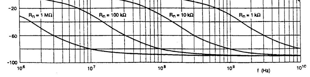
17 DOC NO: SYS-ENG-205 PAGE: 17 of Frequency Response (To be tested upon customer s request) Resistors are designed to function according to ohmic laws. This applied for rectangular chip resistors for frequencies up to 100K Hz. Chip resistors are represented by an ideal resistor switched in series with a coil and both switched parallels to a capacitor. The dimensions of the terminations and the conductive path length mainly determine the values of the capacitance and inductance. The trimming patterns has a negligible influence on the inductance as the path length is not influenced. Its influence on the capacitance is negligible as the total capacitance is largely determined by the terminations. The environment surrounding chips has a large influence on the behavior of the chip on the printed-circuit board. Typical values of Capacitance and Inductance Capacitance 0.05 pf 0.09 pf 0.05 ph Inductance 2 nh 1 nh 0.4 nh
18 DOC NO: SYS-ENG-205 PAGE: 18 of 40 Size 0402: Impedance as a function of frequency for a chip resistor


19 DOC NO: SYS-ENG-205 PAGE: 19 of 40 Size 0603: Impedance as a function of frequency for a chip resistor Size 0603: Phase shift as a function of frequency for a chip resistor


20 DOC NO: SYS-ENG-205 PAGE: 20 of 40 Size 0805 : Impedance as a function of frequency for a chip resistor Size 0805: Phase shift as a function of frequency for a chip resistor


21 DOC NO: SYS-ENG-205 PAGE: 21 of 40 Size 1206 : Impedance as a function of frequency for a chip resistor Size 1206: Phase shift as a function of frequency for a chip resistor
22 DOC NO: SYS-ENG-205 PAGE: 22 of 40 Pulse load Behavior (To be tested upon customer s request) The load that cause chip resistor to open circuit is determined by the shape and time of a single pulse. Parameter Value Exponential time constant (us) 50 to 700 Repetition time (s) 12 to 25 Amount of pulses 5 to 10 With this test, it can be determined at which applied voltage the resistive value changes about 0.5% of its nominal value under the above mentioned pulse conditions. Figure A
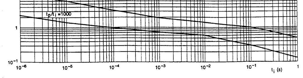
23 DOC NO: SYS-ENG-205 PAGE: 23 of 40 Figure B Single pulse The resistor is considered to be operating under single pulse conditions if, it is loaded with a limited number (approx. 1500) of pulses over long time intervals (> 1 hours). Repetitive Pulse The resistor is operating under repetitive pulse conditions if, it is loaded by a continuous train of pulses of similar power. The resistor must withstand a continuous train of pulses of repetition time t p during which only a small resistance change is acceptable. The resistance change is equal to change permissible under continuous load conditions. The continuous pulse train and small permissible resistance change reduces the maximum handling capability. Measurements of experiment have shown that the handling capability of chip resistor varies with the resistive value applied. Maximum peak pulse voltages as indicated below should not be exceeded.
24 DOC NO: SYS-ENG-205 PAGE: 24 of 40 Figure C Determination of Pulse load Fig B & C may be used to determine the maximum pulse load for a resistor. Repetitive rectangular pulses Repetitive exponential pulses Single rectangular pulses (V 2 i /R) < P max given by the solid lines of Fig. B for the applicable value of t i and duty cycle t p /t I V i < V max given in Fig C for the applicable value of t i As for rectangular pulses, except that t i =0.5 T (V 2 i /R) < P max given by dashed lines of Fig B for the applicable value of t i V i < V max given in Fig C for the applicable value of t i
25 DOC NO: SYS-ENG-205 PAGE: 25 of 40 Pulses may not be applied on a regular basis Figure D: 1206 Figure E: 0805
26 DOC NO: SYS-ENG-205 PAGE: 26 of 40 Figure F: 0603


27 DOC NO: SYS-ENG-205 PAGE: 27 of 40 Pulses applied on a regular basis Figure G, 1206 : Maximum permissible peak pulse power (P max) as a function of pulse duration for R 10kΩ, single pulse and repetitive pulse t p /t i = 1000 Figure H, 0805 : Maximum permissible peak pulse power (P max) as a function of pulse duration for R 10kΩ, single pulse and repetitive pulse t p /t i = 1000.


 as a function")
28 DOC NO: SYS-ENG-205 PAGE: 28 of 40 Figure 1, 0603 : Maximum permissible peak pulse power (P max) as a function of pulse duration for R 10kΩ, single pulse and repetitive pulse t p /t i = Pulses applied on a regular basis Figure J, 1206 : Maximum permissible peak pulse voltage (V max) as a function of pulse duration
 as a")

29 DOC NO: SYS-ENG-205 PAGE: 29 of 40 Figure K, 0805 : Maximum permissible peak pulse voltage (V max) as a function of pulse duration Figure L, 0603 : Maximum permissible peak pulse voltage (V max) as a function of pulse duration.
30 DOC NO: SYS-ENG-205 PAGE: 30 of Soldering Profile Flow Soldering Soldering temperature 245~260 C Double wave 4~6 seconds Pre-heat temperature 90~130 C (Soldering side) 40~60 seconds 30~45 seconds Pre-heat zone Reflow Soldering 230 C ~ 250 C Reflow zone 30~40 seconds 130~180 C Pre-heat zone 60~120 seconds
31 DOC NO: SYS-ENG-205 PAGE: 31 of TAPING 7.1 Structure of Taping Taping of Rectangularly Punched Carrier System Top Cover Tape Rectangularly Punched Carrier Tape Sprocket hole Bottom Cover Tape Rectangularly-hole Component Compartment 7.2 Materials (1) Every taping shall consist of materials as shown in Table 4 (2) Every taping shall not adversely affect the mechanical, electrical and solderability performances. (3) Materials of taping shall generate no static. (4) The taped products are stored at a temperature -5 to +40 C and a relative humidity 40 to 50% without exposing to direct sunlight and, after such conditioning, the tape shall show no deterioration in performances such as change in adhesion force or peel forces. Tables 4 Materials of Taping Carrier Top Cover Bottom Cover Tape Tape Tape Taping of Rectangularly Paper thermal thermal adhesion adhesion Punched Carrier System polyester paper
32 DOC NO: SYS-ENG-205 PAGE: 32 of Leader and Trailer Tape 1) Leader Tape The length of leader tape shall be at least 500 mm including 40 or more or rectangular holes (component compartments) in which no component is placed. The said 40 or more empty component compartments shall be sealed with the top cover tape (see Fig. 2). 2) Trailer Tape The trailer tape at the hub of reel shall be least 40 mm in length including carrier tape with empty component compartments. The empty component compartments shall be sealed with the top cover tape. The last portion of the carrier tape shall release from the reel hub. Fig. 2 Explanation of Leader and Trailer Tape Trailer 40mm min. Portion equipped with surface mounting devices Leader 500mm min. Direction of unreeling Empty Component Compartment ( 40 hole min.) 7.4 Position of Taped component The angle made by the center line of taped component and the center line of component compartment shall not exceed 20 degrees (see Fig. 3). Fig. 3 Angle between Center Line of Component and Center Line of Component compartment
33 DOC NO: SYS-ENG-205 PAGE: 33 of Dimension Dimension of Punched Paper Tape Carrier System (CR - 05 & 10) Remark : Pitch tolerance over any 10 pitches of Po is ± 0.2 mm Dimension of Punched Paper Tape Carrier System (CR- 05 & 10) (unit : mm) Code A B W E F P 1 CR ± ± ± ± ± ± 0.05 CR ± ± ± ± ± ± 0.05 Code P 2 P 0 D 0 T 2 T CR ± ± max -- CR ± ± ±0.1 --
34 DOC NO: SYS-ENG-205 PAGE: 34 of Dimension of Punched Paper Tape Carrier System (CR16, 21, 32, 40, 50, 63) P2 = E F W Remark : Pitch tolerance over any 10 pitches of Po is ± 0.2 mm Dimension of Punched Paper Tape Carrier System (CR - 16, 21, 32, 40) Code A B W E F P1 Do T2 CR ± ± ± 0.1 CR ± ± ± ± ± ± ± ± 0.1 CR ± ± ± 0.1 CR ± ± ± 0.1 Dimension of Plastic Embossed Carrier System (CR -50, 63) Code A B W E F P1 Do T1 CR ± ± ± ± ± ± ± 0 0.2± 0.10 CR ± ± 0.1
35 DOC NO: SYS-ENG-205 PAGE: 35 of Performance of Taping Strength of carrier tape and top cover tape When a tensile force of 10N (1.02 kgf) is applied in the direction of unreeling the tape, the carrier tape and top cover tape shall withstand this force Peel force of top cover tape a) Ensure that the peel force meter is reset to φ initially. b) A minimum of 4 holes is required when the top cover tape is pulled. c) Do not reset the peel force meter. d) The peel force of top cover tape shall be 0.1N to 0.7N (10 to 70 gf) when the top cover tape is pulled at a speed of 300 mm/min with the angle between the tape during peel and the direction of unreeling maintained at 165 to 180 degree as illustrated in Fig 4. Direction of pull 165 to 180 Rectangularly punched carrier tape Direction of unreeling Bottom cover tape Minimum Bending Radius When the tape is bent with the minimum bending radius specified in Fig 5 and Table 5, components shall maintain their position and shall be free from abnormalities such as damage. Table Width of Tape Fig. 4 Peeling Test Minimum Bending Radius 8 mm 30 mm 12 mm 30 mm Fig. 5 Explanation of Minimum Bending Radius Minimum bending Radius (R)
 or one whichever is the larger, and no consecutive missing chip exceeding two is allowed. 7.")
36 DOC NO: SYS-ENG-205 PAGE: 36 of Numbering of missing components and mistake in taping a) The number of missing components shall not exceed 0.1% of the total number of components ( marked number ) or one whichever is the larger, and no consecutive missing chip exceeding two is allowed. 7.7 Packaging b) No mistake is allowed on the position of polarity or termination or front and rear of component at the time of taping Taping Quantity Tape and Reels Code Quantity Remarks CR pcs or pcs on request CR pcs CR16 CR pcs CR32 CR pcs - CR pcs - CR pcs Quantity - Bulk Cassette or pcs on request Code Quantity Remarks CR pcs pcs on request CR pcs - CR pcs - CR pcs Identification Production label that indicates the 12 digits lot number, product type, resistance value and tolerance shall be pasted on the surface of each reel. Marking Lot Number Manufacturing Part Description Reel Qty Manufacturing Part Number How to read lot number : XXXX XX XX XXXX Year Mth Day Serialize Number


37 DOC NO: SYS-ENG-205 PAGE: 37 of 40 Lot Number : 8 digit running numbers Date Code : YYYYMMDD YYYY - Year MM - Month DD - Day Lot Number: 8 digits running numbers Date Code: YYYYMMDD YYYY - Year MM - Month DD - Date Manufacturing Part number Part Description Packaging Reel Box Dimension Reel Box Number of Reels mm 25K Box mm 50K Box 10
38 DOC NO: SYS-ENG-205 PAGE: 38 of Reel Dimensions D C B r B W1 A W t Model A B C D W W 1 t r 7 Reel (5K) φ178±2.0 φ80min 13± 0.2 φ2.0± ± max 1.0± (except K) 7 Reel (4K) φ178±2.0 φ60min 13± 0.2 φ2.0± ± max 1.2± Reel (10K) φ254±2.0 φ60min 13± 0.2 φ2.0± ± max 1.5± Reel (20K) φ330±2.0 φ60min 13± 0.2 φ2.0± ± max 2.1± 0.1 -
39 DOC NO: SYS-ENG-205 PAGE: 39 of Bulk Cassette Packaging Bulk Cassette was standardized in March 1992 (EIAJ ET-7201)
40 DOC NO: SYS-ENG-205 PAGE: 40 of Surface Mount Land Patterns A C SMC B Product ( Type ) Land Dimension A B C CR05 (0201) [ 0.3 ] 0.04 [ 1.0 ] [ 0.4 ] CR10 (0402) [ 0.5 ] [ 1.5 ] ~ [ 0.5 ~ 0.6 ] CR10 (0402) [ 0.5 ] [ 1.5 ] ~ [ 0.5 ~ 0.6 ] CR16 (0603) [ 1.0 ] [ 2.7 ] ~ [ 0.5 ~ 0.9 ] CR21 (0805) [ 1.2 ] [ 3.5 ] ~ [ 1.1 ~ 1.3 ] CR32 (1206) [ 2.2 ] [ 5.0 ] ~ [ 1.4 ~ 1.8 ] CR40 ( 1210) [ 2.2 ] [ 5.0 ] ~ [ 2.1 ~ 3.0 ] CR50 ( 2010 ) 0.15 [ 3.9 ] [ 8.4 ] ~ [ 2.1 ~ 3.0 ] CR63 ( 2512 ) [ 5.2 ] [10.5 ] ~ [ 2.5 ~ 4.8 ] 9. APPLICABLE STANDARDS JIS C 5202 JIS C 5223 JIS C 0806 MIL-R MIL-STD-202 IPC/JEDEC J STD /95/EC IEC Test Methods of Fixed Resistors for Electronic Equipment. Fixed Thick Film Chip Resistors, Rectangular Type for Use in Electronic Equipment. Packaging of Electronic Components on continuous tapes (surface mount devices). Resistors, Fixed, Film, Chip, Established Reliability, General Specifications for. Test Methods for Electronic and Electrical Parts. Moisture / Reflow sensitivity classification for non hermetic solid state surface mount devices. RoHS Directive Solderability
A S J ASJ PTE LTD LEAD FREE THIN FILM CHIP RESISTOR SPECIFICATION. Reference No. : SYS-ENG-209. Revision No. : D
 ASJ PTE LTD LEAD FREE THIN FILM CHIP Reference No. : SYS-ENG-209 Revision No. : D DOC NO: SYS-ENG-209 PAGE: 2 of 24 1.0 SCOPE...... 3 2.0 PART NUMBERING SYSTEM...... 3 3.0 RATING....... 3 3.1 Rated Power......
CR0603/CR0805/CR Chip Resistors
 *RoHS COMPLIANT Features RoHS compliant* Power rating at 7 C: CR63 -.1 W, CR85 -.125 W, CR126 -.25 W Tight tolerances of bottom electrode width Suitable for all types of soldering processes Three layer
Chip Resistors / Chip Arrays
 Chip Resistors / Chip Arrays w w w. b o u r n s. c o m I. CR Series Chip Resistors...92 II. CAT/CAY Series Chip Resistor Arrays...96 CAT/CAY 16 Series...96 CAY1 Chip Resistor Array...97 CAY17 Bussed Resistor
Type CPF Series. Thin Film Precision Resistors. Key Features
 Type CPF Series Key Features Thin film precision resistors with TC's to 15ppm and tolerances to 0.05%. Wide range of case sizes from 0201 to 2512 Suitable for all applications where close accuracy and
Type RN73 Series. Thin Film Precision Resistors. Electrical Characteristics. Key Features. Applications
 Type RN73 Series Key Features High precision - TCR 5ppm/ C and 10ppm/ C Tolerance down to 0.01% Thin film (nichrome) Terminal finish electroplated 100% matte Sn Applications Communications Industrial Controls
SMD - Resistors. Pulse Withstanding Thick Film Chip Resistor-SMDP Series. Product: Size: 0603/0805/1206/1210/2010/2512. official distributor of
 Product: Pulse Withstanding Thick Film Chip Resistor-SMDP Series Size: 0603///12// official distributor of 1. Scope Pulse Withstanding Thick Film Chip Resistor-SMDP Series -This specification applies to
 Distributed by: www.jameco.com 1-8-831-4242 The content and copyrights of the attached material are the property of its owner. *RoHS COMPLIANT VERSIONS AVAILABLE Features Lead free version available (see
Thin Film Ultra Precision Resistors
 Type RU73 Series Key Features High precision - TCR 2ppm/ C and 3ppm/ C Tolerance down to 0.01% Thin film (nichrome) Available in standard and high power versions Terminal finish electroplated 100% matte
Thick Film Chip Resistors Product Specification
 1/21 1 Scope This specification is applicable to lead and halogen free RTT series thick film chip resistors. 2 Explanation Of Part Numbers (EX) RTT 03 101 J TP Type Nominal Resistance Resistance Size Tolerance
RMC10,16,20,32,35,50,63 Automotive Grade Page: 1/10
 +5 C +35 C 75% Product specification contained in this data sheet are subject to change at any time without notice If you have any questions or a Purchasing Specification for any quality Agreement is necessary,
Sp e c i f i c a t i o n
 K M Y Last update: 2013.12.1 No.RMC-K-HTS-0006-8 (Uncontrolled copy) Sp e c i f i c a t i o n (Reference) Style: FIXED THICK FILM CHIP RESISTORS; RECTANGULAR TYPE RMC1/32,1/20,1/16S,1/16,1/10,1/8,1/4,1/2,1
Data sheet. FIXED RECTANGULAR TYPE RMC10,16,20,32,35 Automotive Grade AEC-Q200 qualified RoHS COMPLIANCE ITEM Halogen and Antimony Free
 Spec. No.: RMC-1K-17N1011 /1 Date: 2017. 11. 28 Data sheet Title: Style: FIXED RECTANGULAR TYPE RMC10,16,20,32,35 Automotive Grade AEC-Q200 qualified RoHS COMPLIANCE ITEM Halogen and Antimony Free Note:
Thin Film Current Sensing Chip Resistor (TCS Series)
") (TCS Series) Features -Thin film process -High power rating up to 3 Watts in 2512 size -Tight tolerance down to ±0.5% -Extremely low TCR down to PPM/ C -Resistance values from 50m to 1ohm -High purity
(TCS Series) Features -Thin film process -High power rating up to 3 Watts in 2512 size -Tight tolerance down to ±0.5% -Extremely low TCR down to PPM/ C -Resistance values from 50m to 1ohm -High purity
Data sheet FIXED THICK FILM CHIP RESISTORS; RECTANGULAR TYPE AND HIGH POWER ANTI SURGE. AEC-Q200 qualified
 Spec. No.: RBX K HTS-1 /2 Date: 217. 4. 21 Data sheet Title: Style: FIXED THICK FILM CHIP RESISTORS; RECTANGULAR TYPE AND HIGH POWER ANTI SURGE RBX16,2,32,35 AEC-Q2 qualified RoHS COMPLIANCE ITEM Halogen
Surge Withstanding Thick FilmResistors(SWCR Series)
") Surge Withstanding Thick FilmResistors(SWCR Series) Features: Excellent surge and pulse withstanding performance Higher power rating than General Purpose Thick Film Resistors Offered in to sizes RoHS &
Surge Withstanding Thick FilmResistors(SWCR Series) Features: Excellent surge and pulse withstanding performance Higher power rating than General Purpose Thick Film Resistors Offered in to sizes RoHS &
RALEC 旺詮. Scope: 2 (EX) request. IE-SP /01/05. Released Date Page No. Remark. Series. Resistance Tolerance. Nominal Resistance.
 request. IE-SP /01/05. Released Date Page No. Remark. Series. Resistance Tolerance. Nominal Resistance.") RTH High Power Thick Film Chip Document No. Released Date Page No. IE-SP-030 2018/01/05 1 1 Scope: 1.1 This specification is applicable to lead-free and halogen-free RTH series high power thick film chip
RTH High Power Thick Film Chip Document No. Released Date Page No. IE-SP-030 2018/01/05 1 1 Scope: 1.1 This specification is applicable to lead-free and halogen-free RTH series high power thick film chip
Metal Film Precision Resistor. Features
 Features -Excellent overall stability -Tight tolerance down to ±0.1% -Extremely low TCR down to ±10 PPM/ C -High power rating up to 1 Watts Applications -Telecommunication -Medical Equipment Construction
Metal Film Precision Resistor. Features
 Features -Excellent overall stability -Tight tolerance down to ±0.1% -Extremely low TCR down to ±10 PPM/ C -High power rating up to 1 Watts Applications -Telecommunication -Medical Equipment Construction
Thin Film Precision Chip Resistor (AR Series)
") Features Advanced thin film technology Very tight tolerance down to ±0.01% Extremely low down to ±5PPM/C Wide resistance range 1ohm ~ 3Mega ohm Miniature size 0201 available Thin Film Precision Chip Resistor
Features Advanced thin film technology Very tight tolerance down to ±0.01% Extremely low down to ±5PPM/C Wide resistance range 1ohm ~ 3Mega ohm Miniature size 0201 available Thin Film Precision Chip Resistor
SMD High Power Precision Resistors. Type RP73 Series
 Type RP73 Series Key Features High precision - Tolerance down to 0.05% and TCR down to 5PPM Power rating to 1.0W Up to 200V DC operating Terminal finish electroplated 100% matte Sn Applications Communications
Thin Film Precision Chip Resistor (AR Series)
") Construction D1 L (AR Series) Features -Advanced thin film technology -Very tight tolerance down to ±0.01% -Extremely low TCR down to PPM/ C -Wide resistance range 1ohm ~ 3Mega ohm -Miniature size 0201
Construction D1 L (AR Series) Features -Advanced thin film technology -Very tight tolerance down to ±0.01% -Extremely low TCR down to PPM/ C -Wide resistance range 1ohm ~ 3Mega ohm -Miniature size 0201
High Voltage Thick Film Chip Resistors Product Specification
 Page No 1/10 1 Scope: 11 This specification is applicable to lead and halogen free for RTV series thick film chip resistors 12 Lead free products mean lead free termination meets RoHS requirement Pb contained
Pulse Withstanding Thick Film Resistors(PWCR Series)
") Pulse Withstanding Thick Film Resistors(PWCR Series) Features: Excellent pulse withstanding performance Higher power ratings than General Purpose Thick Film Resistors Improved working voltage ratings Offered
Pulse Withstanding Thick Film Resistors(PWCR Series) Features: Excellent pulse withstanding performance Higher power ratings than General Purpose Thick Film Resistors Improved working voltage ratings Offered
SMD MELF - Resistors. Metal Film Precision Resistor - SMDM Series Size: 0204/ official distributor of
 Product : Metal Film Precision Resistor - SMDM Series Size: 0204/ 0207 official distributor of Metal Film Precision Resistor (SMDM Series) 1. Features -Excellent overall stability -Tight tolerance down
Thick Film Chip Resistors. ( Lead Free for RM series standard ) page 1/13
 page 1/13") ( Lead Free for RM series standard ) page 1/13 1. Scope : This specification applies for the RM series of thick film chip resistors made by. 2. Construction: Over Coat Conductor : (Lead-free or with lead
( Lead Free for RM series standard ) page 1/13 1. Scope : This specification applies for the RM series of thick film chip resistors made by. 2. Construction: Over Coat Conductor : (Lead-free or with lead
SMD High Power Precision Resistors. Type RP73 Series
 Key Features High precision - Tolerance down to 0.05% and TCR down to 5PPM Power rating to 1.0W Up to 200V DC operating Terminal finish electroplated 100% matte Sn Applications Communications Industrial
SPECIFICATION FOR APPROVAL 1/8W 0816 LOW RESISTNACE CHIP RESISTOR
 PAGE : 1 OF 11 1/8W 0816 LOW RESISTNACE CHIP RESISTOR 1. Scope This specification applies to 0.8mm x 1.60mm size 1/8W, fixed metal film chip resistors rectangular type for use in electronic equipment.
Tel: /Fax: , Kuanfu N Road, HsinChu Industrial Park, 303 Taiwan, ROC 1
 70, Kuanfu N Road, HsinChu Industrial Park, 303 Taiwan, ROC 1 Thin Film Precision Chip Resistors (AR Series) 1. Scope This specification applies to all sizes of rectangular-type fixed chip resistors with
SMD Resistor Networks
 Product: Size: Thick Film Array Chip Resistor-SMRA Series 42x4 / 63x4 / 42x4(Concave) / 63x4(Concave) 42x8 official distributor of Thick Film Array Chip Resistor-SMRA Series 1. Scope -This specification
Data Sheet. Chun Ann J.C Liu. Customer: Thin Film Precision Chip Resistor - AR Series. Checked. Product :
 Data Sheet Customer: Product : Thin Film Precision Chip Resistor - AR Series Size: 0201/0402/0603/0805/1206/1210/2010/2512 Issued Date: 19-Aug-10 Edition : REV.C6 Produced by Checked Approved by Prepared
Data sheet ESD SUPPRESSOR; RECTANGULAR TYPE. AEC-Q200 qualified. RoHS COMPLIANCE ITEM Halogen and Antimony Free
 No.: HSPC K HTS 0001 /4 Date: 2017. 4. 21 Data sheet Title: Style: HSPC10, 16 AEC-Q200 qualified RoHS COMPLIANCE ITEM Halogen and Antimony Free Note: Stock conditions Temperature: +5 C +35 C Relative humidity:
Data sheet FIXED THICK FILM CHIP RESISTORS; RECTANGULAR TYPE & ANTI-SULFURATION. AEC-Q200 qualified. RoHS COMPLIANCE ITEM Halogen and Antimony Free
 No.: RMAW K HTS-0001 /5 Date: 2017. 4. 21 Data sheet : ANTI-SULFURATION RMAW10,16,20,32 AEC-Q200 qualified RoHS COMPLIANCE ITEM Halogen and Antimony Free Note: Stock conditions Temperature: +5 C +35 C
Thick Film Chip Resistor Arrays Thick Film Chip Resistor Networks (Lead-Free for CN Series Standard)
") page number 1 /12 1. Scope : This specification applies for the CN series of thick film chip resistor arrays & chip resistor networks made by MQEC. 2. Construction, Dimensions, Schematic : 2.1 Construction
page number 1 /12 1. Scope : This specification applies for the CN series of thick film chip resistor arrays & chip resistor networks made by MQEC. 2. Construction, Dimensions, Schematic : 2.1 Construction
SPECIFICATION FOR APPROVAL. 1/8W, 0402, Low Resistance Chip Resistor (Lead / Halogen Free)
") DOCUMENT REVISION : SRK220000NH : A2 SPECIFICATION FOR APPROVAL PAGE : 1 OF 9 1/8W, 0402, Low Resistance Chip Resistor (Lead / Halogen Free) 1. Scope This specification applies to1.0mm x 0.5mm size 1/8W,
DOCUMENT REVISION : SRK220000NH : A2 SPECIFICATION FOR APPROVAL PAGE : 1 OF 9 1/8W, 0402, Low Resistance Chip Resistor (Lead / Halogen Free) 1. Scope This specification applies to1.0mm x 0.5mm size 1/8W,
Thick Film Chip Resistors ( Lead-Free for RM series standard )
") page number 1/15 1. Scope : This specification applies for the RM series of thick film chip resistors made by TA-I. 2. Construction: Over Coat (Color : Black) Conductor Sn Plating Ceramic Substrate Resistive
page number 1/15 1. Scope : This specification applies for the RM series of thick film chip resistors made by TA-I. 2. Construction: Over Coat (Color : Black) Conductor Sn Plating Ceramic Substrate Resistive
Low Resistance Flat Chip Resistors Type SR73
 Low Resistance Flat Chip Resistors Type SR73 1. Scope This specification applies to chip resistors (SR73) produced by KOA Corporation. CERTIFIED AHA 9/29/11 CERTIFIED 2. Type Designation The type designation
DATA SHEET SURFACE-MOUNT CERAMIC MULTILAYER CAPACITORS High-voltage SC type: NP0/X7R (Pb Free & RoHS compliant)
") DATA SHEET SURFACE-MOUNT CERAMIC MULTILAYER CAPACITORS High-voltage SC type: (Pb Free & RoHS compliant) 2.2 pf to 4.7 nf Product specification Mar 1, 2007 V. 0 Product specification 2 SCOPE This specification
DATA SHEET SURFACE-MOUNT CERAMIC MULTILAYER CAPACITORS High-voltage SC type: (Pb Free & RoHS compliant) 2.2 pf to 4.7 nf Product specification Mar 1, 2007 V. 0 Product specification 2 SCOPE This specification
SPECIFICATIONS. Metal Film Precision Resistor. CSR-Serie SWISSDIS. Swissdis AG Grasweg 7 CH-4911 Schwarzhäusern
 SWISSDIS Swissdis AG Grasweg 7 CH-4911 Schwarzhäusern Tel.: +41 62 919 44 00 Fax: +41 62 919 44 01 info@swissdis.ch www.swissdis.ch SPECIFICATIONS CSR-Serie Version June 2017 Features -Excellent overall
SMD CHIP RESISTOR. How To Order: RC 0603 J 2K3 B 10. Tolerance: Size: Pcs/reel Chip. Resistance: Series: Size of B=0.1% 1R=1 ohm.
 SMD CHIP RESISTOR How To Order: Series: RC Part No.: RC 0603 J 2K3 B 10 Series: Size: Tolerance: Resistance: Size of Pcs/reel Chip 0201 B=0.1% 1R=1 ohm Reel 10=10k/reel Resistor 0402 D=0.5% 2.3R=2R3 B=13
DATA SHEET GENERAL PURPOSE CHIP RESISTORS RC1218 (Pb Free) 5%; 1% Product specification Oct 13, 2004 V.1
 5%; 1% Product specification Oct 13, 2004 V.1") DATA SHEET GENERAL PURPOSE CHIP RESISTORS 5%; 1% 2 SCOPE This specification describes 1218 series chip resistors with lead-free terminations made by thick film process. ORDERING INFORMATION Part number
DATA SHEET GENERAL PURPOSE CHIP RESISTORS 5%; 1% 2 SCOPE This specification describes 1218 series chip resistors with lead-free terminations made by thick film process. ORDERING INFORMATION Part number
Automotive Grade Thick Film Array Chip Resistor
 CN.. Series Scope -This specification applies to all sizes of rectangular-type fixed chip resistors with Ruthenium-base as material. Features -EC-Q200 Compliance -Small size and light weight -Reduction
SPECIFICATION FOR APPROVAL. 1/32W, Low Resistance Chip Resistor (Lead / Halogen free)
") PAGE : 1 OF 7 1/32W, 01005 Low Resistance Chip Resistor (Lead / Halogen free) 1. Scope This specification applies 0.2mm x 0.4mm (01005) size 1/32W, fixed metal film chip resistors rectangular type for
PAGE : 1 OF 7 1/32W, 01005 Low Resistance Chip Resistor (Lead / Halogen free) 1. Scope This specification applies 0.2mm x 0.4mm (01005) size 1/32W, fixed metal film chip resistors rectangular type for
50W TO220 High Power Resistors
 50W TO220 High Power Resistors MHP 50 Non-inductive, thin film technology. Thermally enhanced Industry standard TO220 package. RoHS compliant. Low thermal resistance, 2.3 C/W resistor hot spot to metal
Thick Film Chip Resistor Arrays Thick Film Chip Resistor Networks. (Lead-Free for CN34 Series) page 1/10
 page 1/10") (Lead-Free for CN34 Series) page 1/10 1. Scope : This specification applies for the CN34 series of thick film chip resistor arrays made by TA-I. 2. Construction, Dimensions, Schematic : 2.1 Construction
(Lead-Free for CN34 Series) page 1/10 1. Scope : This specification applies for the CN34 series of thick film chip resistor arrays made by TA-I. 2. Construction, Dimensions, Schematic : 2.1 Construction
SPECIFICATIONS. Metal Film Precision Resistor. CSRV-Serie SWISSDIS. Swissdis AG Grasweg 7 CH-4911 Schwarzhäusern
 SWISSDIS Swissdis AG Grasweg 7 CH-4911 Schwarzhäusern Tel.: +41 62 919 44 00 Fax: +41 62 919 44 01 info@swissdis.ch www.swissdis.ch SPECIFICATIONS Metal Film Precision Resistor CSRV-Serie Version August
Thick Film Array Chip Resistor
 CN Series Scope -This specification applies to all sizes of rectangular-type fixed chip resistors with Ruthenium-base as material. Features -Small size and light weight -Reduction of assembly costs and
This specification applies for the RMS series of Anti-Sulfurated thick film chip resistors made by TA-I. RMS 10 J T 103.
 page number 1/13 1. Scope : This specification applies for the RMS series of Anti-Sulfurated thick film chip resistors made by TA-I. 2. Construction: Over Coat (Color : Black) Conductor Sn Plating Ceramic
FrelTec GmbH. Current Sensing Chip Resistor SMD
 GmbH Mathildenstr. 10A 82319 Starnberg Germany SMD 6/8/2015 1/13 Freltec GmbH www.freltec.com SPECIFICATION Part Number 017 05 * R001 * J * T05 ** D E Size Value Tolerance Packing TCR Power Rating 017
DATA SHEET FUSIBLE CHIP RESISTORS FR series (Pb Free) 5% sizes 0603/1206. Product specification Sep 26, 2005 V.0
 5% sizes 0603/1206. Product specification Sep 26, 2005 V.0") DATA SHEET FUSIBLE CHIP RESISTORS series (Pb Free) 5% sizes 0603/1206 2 Chip Resistor Surface Mount SCOPE This specification describes 0603/1206 fusible chip resistors with leadfree terminations made by
DATA SHEET FUSIBLE CHIP RESISTORS series (Pb Free) 5% sizes 0603/1206 2 Chip Resistor Surface Mount SCOPE This specification describes 0603/1206 fusible chip resistors with leadfree terminations made by
Thick Film Chip Resistor
 Thick Film Chip resistors, which are available for surface mounting, are general passive component which is useful for voltage drop, current controlling in circuit and surface mounting is available. Samsung
Over Coat. Resistive Element RBS 10 B T P Product Code Size Tolerance Packaging TCR Nominal. e.g., (1608) 1/10W.
 1/10W.") page 1/10 1. Scope : This specification applies for the RBS series of chip resistors made by TA-I. 2. Construction: Over Coat Sn Plating Ni Plating Resistive Element Ceramic Substrate Inner electrode 3.
page 1/10 1. Scope : This specification applies for the RBS series of chip resistors made by TA-I. 2. Construction: Over Coat Sn Plating Ni Plating Resistive Element Ceramic Substrate Inner electrode 3.
FrelTec GmbH. Thin Film Chip Resistor SMD Precision (1% to 0,1%) Low TCR (10, 15, 25 and 50 ppm)
 Low TCR (10, 15, 25 and 50 ppm)") GmbH Mathildenstr. 10A 82319 Starnberg Germany Thin Film Chip Resistor SMD Precision (1% to 0,1%) Low TCR (10, 15, 25 and 50 ppm) 8/31/2011 1/15 Freltec GmbH www.freltec.com SPECIFICATION Part Number 030
GmbH Mathildenstr. 10A 82319 Starnberg Germany Thin Film Chip Resistor SMD Precision (1% to 0,1%) Low TCR (10, 15, 25 and 50 ppm) 8/31/2011 1/15 Freltec GmbH www.freltec.com SPECIFICATION Part Number 030
Metal Film Precision Resistor. Features
 Features -Excellent overall stability -Tight tolerance down to ±0.1% -Extremely low TCR down to ±10 PPM/ C -High power rating up to 1 Watts Construction & Dimension 6 5 1 2 3 4 Applications -Telecommunication
Selection Series: E24 & E96 E24 & E96 Temp. Coefficient (ppm/ C):
:") Thin Film Precision Resistors 1206 1210 Rated Power @ 70 C: 0.125W 0.2W Resistance Range (Ohms) Min: 4R7 4R7 4R7 1R0 4R7 1R0 4R7 4R7 4R7 1R0 4R7 1R0 Max: 1M0 2M5 1M0 2M5 1M0 2M5 1M0 2M5 1M0 2M5 1M0 2M5
Thin Film Precision Resistors 1206 1210 Rated Power @ 70 C: 0.125W 0.2W Resistance Range (Ohms) Min: 4R7 4R7 4R7 1R0 4R7 1R0 4R7 4R7 4R7 1R0 4R7 1R0 Max: 1M0 2M5 1M0 2M5 1M0 2M5 1M0 2M5 1M0 2M5 1M0 2M5
Precision Thin Film Precision Resistors
 Key Features Thin film precision resistors with TC's of 15ppm, 25ppm and 50ppm and tolerances to 0.1%. Applications in measurement, telemetry and for sensing circuits. Case sizes 0402, 0603, 0805, 1206,
Pulse Withstanding Chip Resistors
 Construction 1 Alumina Substrate Features: Tolerance from ±0.5% to 5%. High power rating. Excellent pulse withstanding performance. Improved working voltage ratings. Standard package sizes of 0805 to 2512.
DATA SHEET GENERAL PURPOSE CHIP RESISTORS RC0603 (Pb Free) 5%, 1%
 5%, 1%") DATA SHEET GENERAL PURPOSE CHIP RESISTORS 5%, 1% Product specification Supersedes Date of Mar. 06, 2003 Product specification 2 SCOPE This specification describes 0603 series chip resistors with lead-free
DATA SHEET GENERAL PURPOSE CHIP RESISTORS 5%, 1% Product specification Supersedes Date of Mar. 06, 2003 Product specification 2 SCOPE This specification describes 0603 series chip resistors with lead-free
Chip Array Resistor INTRODUCTION FEATURE AND APPLICATION. Feature. Application
 INTRODUCTION Chip array resistors are general passive component which is useful for derating voltage, current controlling in circuit and surface mounting is available. Samsung electro-mechanics manufactures
DATA SHEET FUSIBLE CHIP RESISTORS FR series (Pb Free) 5% sizes 0603/1206. Product specification Sep 26, 2005 V.0
 5% sizes 0603/1206. Product specification Sep 26, 2005 V.0") DATA SHEET FUSIBLE CHIP RESISTORS series (Pb Free) 5% sizes 0603/1206 Product specification Product specification 2 SCOPE This specification describes 0603/1206 fusible chip resistors with leadfree terminations
DATA SHEET FUSIBLE CHIP RESISTORS series (Pb Free) 5% sizes 0603/1206 Product specification Product specification 2 SCOPE This specification describes 0603/1206 fusible chip resistors with leadfree terminations
DATA SHEET THIN-FILM CHIP RESISTORS TF 13 series, 0.1% TC25
 DATA SHEET THIN-FILM CHIP RESISTORS TF 13 series, 0.1% TC25 10 Ω TO 1 MΩ Product Specification Jul 10, 2003 V.3 FEATURES High precision High long-tem stability Low temperature coefficient. APPLICATIONS
Chip Resistor INTRODUCTION FEATURE AND APPLICATION. Feature. Application
 INTRODUCTION Chip resistors are general passive component which is useful for derating voltage, current controlling in circuit and surface mounting is available. Samsung electro mechanics also manufactures
Thick Film Chip Resistors Low Resistance ( for 0402 ) This specification applies for the RL04 ( 0402 ) of thick film chip resistors made by TA-I.
 This specification applies for the RL04 ( 0402 ) of thick film chip resistors made by TA-I.") page 1 / 8 1. Scope : This specification applies for the RL04 ( 0402 ) of thick film chip resistors made by TA-I. 2. Construction: Over Coat Conductor : (Lead-free or with lead ) Sn Plating Ceramic Substrate
page 1 / 8 1. Scope : This specification applies for the RL04 ( 0402 ) of thick film chip resistors made by TA-I. 2. Construction: Over Coat Conductor : (Lead-free or with lead ) Sn Plating Ceramic Substrate
DATA SHEET GENERAL PURPOSE CHIP RESISTORS RC1206 5%, 1%
 1100 DATA SHEET GENERAL PURPOSE CHIP RESISTORS 1206 5%, 1% RoHS compliant Product specification Jul 02, 200 V.4 Supersedes Date of Mar. 06, 2003 Product specification 2 SCOPE This specification describes
SPECIFICATION FOR APPROVAL. 1/2W, 0603, Low Resistance Chip Resistor (Lead / Halogen free)
") PAGE : 1 OF 7 1/2W, 0603, Low Resistance Chip Resistor (Lead / Halogen free) 1. Scope This specification applies to 0.8mm x 1.6mm size 1/2W, fixed metal film chip resistors rectangular type for use in
PAGE : 1 OF 7 1/2W, 0603, Low Resistance Chip Resistor (Lead / Halogen free) 1. Scope This specification applies to 0.8mm x 1.6mm size 1/2W, fixed metal film chip resistors rectangular type for use in
PRODUCT DATASHEET. is brought to you by. SOS electronic distribution of electronic components
 PRODUCT DATASHEET is brought to you by SOS electronic distribution of electronic components Click to view availability, pricing and lifecycle information. Visit https://www.soselectronic.com/ Datasheet
Electrical Specifications. Maximum Maximum Resistance Working Overload Temperature. Mechanical Specifications
 Features: Thin Film Technology for precision and stability Excellent power to size ratio Exhibits good pulse power characteristics RoHS compliant / lead-free Type / Code MLF12 0207 MLFM1 Package Size 0207
Data Sheet. Customer: Pulse Withstanding Chip Resistor - PWR Series Size: 0603/0805/1206/1210/2010/2512 Issued Date: 13-Oct-17
 Data Sheet Customer: Product: - Size: 0603/0805/1206/1210/2010/2512 Issued Date: 13-Oct-17 Edition: REV.C3 VIKING TECH CORPORATION VIKING TECH CORPORATION KAOHSIUNG BRANCH WUXI TMTEC CO., LTD. No.70 Guangfu
DATA SHEET GENERAL PURPOSE CHIP RESISTORS RC1206 5%, 1%, 0.5%, 0.1% Product specification June 25, 2014 V.5. RoHS compliant
 Product specification June 25, 2014 V.5 1100 DATA SHEET GENERAL PURPOSE CHIP RESISTORS 1206 5%, 1%, 0.5%, 0.1% RoHS compliant Product specification 2 SCOPE This specification describes 1206 series chip
DATA SHEET GENERAL PURPOSE CHIP RESISTORS RC0603 5%, 1%, 0.5%, 0.1% Product specification July 01, 2014 V.5 Supersedes Date of Mar.
 Product specification July 01, 2014 V.5 Supersedes Date of Mar. 06, 2003 DATA SHEET GENERAL PURPOSE CHIP RESISTORS 0603 5%, 1%, 0.5%, 0.1% RoHS compliant Product specification 2 hahah SCOPE This specification
MELF Coated Thin Film Precision Resistors (MELFC Series)
") Features: Precision TCR of 0, 5, 25 & 50ppm/ C High reliability and stability of ±0. and ±0.5% Excellent pulse load capability Strong mechanical body due to cylindrical shape AEC-Q200 compliant RoHS and
Features: Precision TCR of 0, 5, 25 & 50ppm/ C High reliability and stability of ±0. and ±0.5% Excellent pulse load capability Strong mechanical body due to cylindrical shape AEC-Q200 compliant RoHS and
Version: 1.2 Document code:ma2512 Effective date : Page: 1 of 7. Metal Alloy shunt resistor MA2512 series ROHS
 Document code: Page: 1 of 7 Metal Alloy shunt resistor series ROHS Metal Alloy Shunt Resistor Specification Document code: Page: 2 of 7 Metal Alloy shunt resistor series ROHS Scope This specification applies
Surge Withstanding Chip Resistor SWR Series
 SR Series Features -High power rating -Excellent surge withstanding & pulse withstanding performance -Improved working voltage ratings -Standard package sizes of 0603~ -EC-Q200 Compliance pplications -Metering
PRODUCT SPECIFICATION
 PRODUCT SPECIFICATION Description: CRGH Series Product Type: (Resistance range: 1.0Ω ~ 10MΩ) CRGH0603_XXX (CRGH0603 1/5W +/- 1% & 5% Taped) CRGH0805_XXX (CRGH0805 1/3W +/- 1% & 5% Taped) CRGH1206_XXX (CRGH1206
Chip Resistors Pulse Withstanding
 Features: Tolerance from ±0.5% to 5% High power rating Excellent pulse withstanding performance Improved working voltage ratings Standard package sizes of 0603 to 2512 Applications: Metering (Testing/Measurement)
DATA SHEET GENERAL PURPOSE CHIP RESISTORS RC0603 5%, 1%, 0.5% RoHS compliant
 DATA SHEET GENERAL PURPOSE CHIP RESISTORS 0603 5%, 1%, 0.5% RoHS compliant Product specification February 05, 2013 V.6 Supersedes Date of Mar. 06, 2003 Product specification 2 SCOPE This specification
PRODUCT SPECIFICATION
 PRODUCT SPECIFICATION Description: CRGH Series Product Type: (Resistance range: 1.0Ω ~ 10MΩ) CRGH0603_XXX (CRGH0603 1/5W +/- 1% & 5% Taped) CRGH0805_XXX (CRGH0805 1/3W +/- 1% & 5% Taped) CRGH1206_XXX (CRGH1206
Metal Foil Low Resistance Chip Resistor MFF Series
 Page No. 1/8 Metal Foil Low Resistance Chip Resistor MFF Series Application Features Entertainment Low Resistance / TCR / EMF/Inductance Power supply Excellent long term stability Measuring instrument
YAGEO CORPORATION SMD RESISTORS. RC Series FEATURES. Extremely Thin and Light. Highly Reliable Multilayer Electrode Construction
 YAGEO CORPORATION SMD RESISTORS Thick Film Chip Resistors RC Series FEATURES Extremely Thin and Light Highly Reliable Multilayer Electrode Construction Compatible with all Soldering Process Highly Stable
DATA SHEET GENERAL PURPOSE CHIP RESISTORS RC0402 5%, 1% RoHS compliant & Halogen Free
 DATA SHEET GENERAL PURPOSE CHIP RESISTORS 5%, 1% RoHS compliant & Halogen Free Product specification Supersedes Date of Mar. 06, 2003 Product specification 2 SCOPE This specification describes series chip
DATA SHEET ARRAY CHIP RESISTORS YC324 (8Pin/4R; Pb Free) 5%, 1% sizes Product specification Feb 22, 2005 V.1 Supersedes Date of Mar.
 5%, 1% sizes Product specification Feb 22, 2005 V.1 Supersedes Date of Mar.") 3 DATA SHEET ARRAY CHIP RESISTORS 324 (Pin/4R; Pb Free) 5%, 1% sizes 1220 Product specification Supersedes Date of Mar. 06, 2003 Product specification 2 SCOPE This specification describes 324 series chip
3 DATA SHEET ARRAY CHIP RESISTORS 324 (Pin/4R; Pb Free) 5%, 1% sizes 1220 Product specification Supersedes Date of Mar. 06, 2003 Product specification 2 SCOPE This specification describes 324 series chip
AEC-Q200 Compliant with AEC-Q200 standard. Miniature and light weight. Suit for reflow and wave flow solder
 Thick Film Chip Fixed Resistor Automotive Grade Features AEC-Q200 Compliant with AEC-Q200 standard Miniature and light weight Suit for reflow and wave flow solder Stable electrical capability,high reliability
SRM VDE. REG.-Nr. E932. Cap Diameter (D1, mm) Body Diameter (D2, mm)
 Body Diameter (D2, mm)") D2 VDE REG.-Nr. E932 Specifications Per IEC 605- Features B L D IEC60065 & UL676 Compliant MELF packaging yet capable of high power handling Special conductive film enhances anti-surge capability. Absorbs
D2 VDE REG.-Nr. E932 Specifications Per IEC 605- Features B L D IEC60065 & UL676 Compliant MELF packaging yet capable of high power handling Special conductive film enhances anti-surge capability. Absorbs
DATA SHEET THICK FILM CHIP RESISTORS Automotive Precision grade AC series 0.1%, 0.5%, 1%, TC 50
 Product specification March 14, 2016 V.0 DATA SHEET THICK FILM CHIP RESISTORS Automotive Precision grade AC series 0.1%, 0.5%, 1%, TC 50 sizes 0402/0603/0805/1206 RoHS compliant & Halogen Free Product
DATA SHEET SURFACE-MOUNT CERAMIC MULTILAYER CAPACITORS High-voltage: NP0/X7R (Pb Free & RoHS compliant)
") w DATA SHEET SURFACE-MOUNT CERAMIC MULTILAYER CAPACITORS High-voltage: NP0/X7R (Pb Free & RoHS compliant) 1K V TO 4K V 10 pf to 33 nf Sep 30, 2005 V. 1 2 SCOPE This specification describes Highvoltage
w DATA SHEET SURFACE-MOUNT CERAMIC MULTILAYER CAPACITORS High-voltage: NP0/X7R (Pb Free & RoHS compliant) 1K V TO 4K V 10 pf to 33 nf Sep 30, 2005 V. 1 2 SCOPE This specification describes Highvoltage
Cut and formed product is available on select sizes; contact factory for details Flameproof coating per UL94 V-0 RoHS compliant / lead-free
 Features: Excellent anti-surge characteristics Stable characteristics through the resistance range Good alternative to carbon composition resistors Applications include power supplies, CRT s, and antisurge
ULTRA LOW POWER SMD METAL STRIP RESISTORS
 Features These specification covers 2512 sized high power low resistance current sensing metal resistors. PART NUMBERING SYSTEM: - 2512 A 1W R005 F E C Type Dimensions Code 2512 Construction Resistance
AEC-Q200 Compliant with AEC-Q200 standard. Miniature and light weight. Suit for reflow and wave flow solder
 Anti-Sulfurated Thick Film Chip Fixed Resistor Automotive Grade Features AEC-Q200 Compliant with AEC-Q200 standard Miniature and light weight Suit for reflow and wave flow solder Stable electrical capability,high
DATA SHEET GENERAL PURPOSE CHIP RESISTORS RC1218 5%, 1% RoHS compliant
 DATA SHEET GENERAL PURPOSE CHIP RESISTORS 121 5%, 1% RoHS compliant Product specification Jul 15, 200 V.2 Supersedes Date of Mar. 06, 2003 Product specification 2 SCOPE This specification describes 121
sizes 0201/0402/0603/0805/1206/1210/1218/2010/2512
 Product specification August 29, 2014 V.2 DATA SHEET ANTI-SULFURATED CHIP RESISTORS AF series 5%, 1%, 0.5% sizes 0201/0402/0603/005/1206/1210/121/2010/2512 RoHS compliant & Halogen free Product specification
FrelTec GmbH. Current Sensing Chip Resistor SMD
 GmbH Mathildenstr. 10A 82319 Starnberg Germany SMD 11/22/2016 1/10 Freltec GmbH www.freltec.com SPECIFICATION Part Number 018 05 * R001 * J * T05 ** E* Type Size Value Tolerance Packing Power Rating 018
DATA SHEET ANTI-SULFURATED CHIP RESISTORS AF series 5%, 1%, 0.5%
 Product specification June 07, 2017 V.5 DATA SHEET ANTI-SULFURATED CHIP RESISTORS AF series 5%, 1%, 0.5% sizes 0201/0402/0603/0805/1206/1210/1218/2010/2512 RoHS compliant & Halogen free Product specification
Application. Features
 Thick Film Chip Resistor CR Series Application Entertainment: Stereo, TV tuners, Tape recorder Appliance: Air conditioner, Refrigerator Computer & relative products: Main board, PDA Communication equipment:
Thick Film Chip Array Resistor
 Date From Dec.. 2004 INTRODUCTION Chip array resistors are general passive component which is useful for derating voltage, current controlling in circuit and surface mounting is available. Samsung electro-mechanics
1. INSTRUCTION: THIS SHEET IS THE STATEMENT OF THE LEAD-FREE THICK FILM CHIP RESISTORS SPECIFICATION THAT UNIOHMS PRODUCTIONS CAN MEET.
 PART NO.: CHIP RESISTORS FILE NO.: CX-01-001 1. INSTRUCTION: THIS SHEET IS THE STATEMENT OF THE LEAD-FREE THICK FILM CHIP RESISTORS SPECIFICATION THAT UNIOHMS PRODUCTIONS CAN MEET. 2. RATING: TYPE 0402
DATA SHEET GENERAL PURPOSE CHIP RESISTORS RC0201 5%, 1% RoHS compliant
 DATA SHEET GENERAL PURPOSE CHIP RESISTORS 0201 5%, 1% RoHS compliant Product specification Supersedes Date of Mar. 06, 2003 Product specification 2 SCOPE This specification describes 0201 series chip resistors
DATA SHEET SURFACE-MOUNT CERAMIC MULTILAYER CAPACITORS Mid-voltage: NP0/X7R (Pb Free & RoHS compliant)
") w DATA SHEET SURFACE-MOUNT CERAMIC MULTILAYER CAPACITORS Mid-voltage: NP0/X7R (Pb Free & RoHS compliant) 100 V TO 500 V 10 pf to 470 nf Product specification Sep 08, 2005 V. 0 Product specification 2 SCOPE
w DATA SHEET SURFACE-MOUNT CERAMIC MULTILAYER CAPACITORS Mid-voltage: NP0/X7R (Pb Free & RoHS compliant) 100 V TO 500 V 10 pf to 470 nf Product specification Sep 08, 2005 V. 0 Product specification 2 SCOPE
Type CRG Series THICK FILM CHIP RESISTORS. Electrical Characteristics. Power rating: Key Features
 Key Features Type CRG Series Thick Film Resistors with high power to size ratio, ideally suited to industrial and general purpose use Value range from Ω to MΩ Eight package sizes Terminal finish matte
DATA SHEET GENERAL PURPOSE CHIP RESISTORS RC1206 5%, 1% RoHS compliant
 100 DATA SHEET GENERAL PURPOSE CHIP RESISTORS 1206 5%, 1% RoHS compliant Product specification Jul 15, 200 V.3 Supersedes Date of Mar. 06, 2003 Product specification 2 SCOPE This specification describes
DATA SHEET GENERAL PURPOSE CHIP RESISTORS RC0402 5%, 1% RoHS compliant
 DATA SHEET GENERAL PURPOSE CHIP RESISTORS 0402 5%, 1% RoHS compliant Product specification Jul 15, 200 V.3 Supersedes Date of Mar. 06, 2003 Product specification 2 SCOPE This specification describes 0402
(HVR) Thick Film High Voltage Chip Resistors. Token Electronics Industry Co., Ltd. Version: February 13, Web:
 Thick Film High Voltage Chip Resistors. Token Electronics Industry Co., Ltd. Version: February 13, Web:") Version: February 13, 2017 (HVR) Thick Film High Voltage Chip Resistors Token Electronics Industry Co., Ltd. Web: www.token.com.tw mailto: Taiwan: No.137, Sec. 1, Zhongxing Rd., Wugu District, New Taipei
Version: February 13, 2017 (HVR) Thick Film High Voltage Chip Resistors Token Electronics Industry Co., Ltd. Web: www.token.com.tw mailto: Taiwan: No.137, Sec. 1, Zhongxing Rd., Wugu District, New Taipei