Hands-On-Relay School 2015 Distribution Event Analysis. Randy Spacek Protection Engineer Manager
|
|
|
- Emory Daniels
- 6 years ago
- Views:
Transcription

1 Hands-On-Relay School 2015 Distribution Event Analysis Randy Spacek Protection Engineer Manager
 Scheme")

2 OVERVIEW Available Tools Fault Type Identification: line and transformer Relay Event Record: Oscillography & Digital Elements Sequence of Events Record Element Pick Up and Logic Approach Distribution Event analysis TRIP to Lockout Sequence SAG 742, fuse operation FAST TRIP BLOCK (FTB) Scheme SPT 4S30 SPU Feeder 121 Operation Homework SAG 741 Failure Analysis Homework Transformer Event Analysis 15kV OPEN PHASE Detection SIP 12F1 Transformer Differential ECL 115/13kV Lolo Autotransformer Operation Homework Transmission Event Analysis DGP Breaker A-538 Directional Elements Boulder Breaker Failure


3 Tools Records One Line Diagram Relay Manual Relay Settings Data SCADA Log Relay SER Relay Event Software Oscillography Phasor
4 Tools: Records-One Line
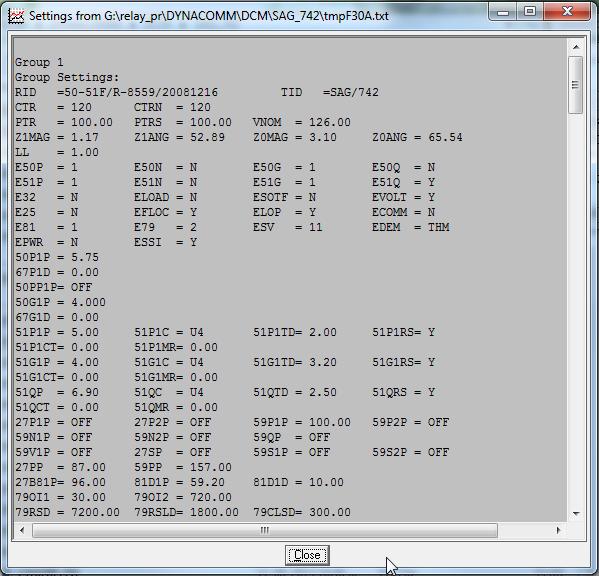
5 Tools: Records-Settings Trip Equation Logic Enables Elements
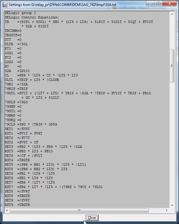
6 Tools: Records-Settings Logic Review:
7 Tools: Data-SCADA LOG Time, Date and sequence of the event
8 SER 2/2/2010 Tools: Data-Relay SER 50-51T/R/R-9631/ Date: 02/04/10 Time: 15:46: STJ/24KV BKR/AUTO XFMR FID=SEL-351R-2-R303-V0-Z D CID=89C9 BCBFID=R107 # DATE TIME ELEMENT STATE status with time stamp /02/10 17:52: C1 Asserted /02/10 17:52: G1 Asserted /02/10 17:52: G1 Asserted /02/10 17:52: A1 Asserted /02/10 17:52: G1T Asserted /02/10 17:52: SV5 Asserted SV5 = TRIP *!3PO /02/10 17:52: SV1 Asserted SV1 = TRIP * (51P1+51G1+51Q) /02/10 17:52: TMB4A Asserted TMB4A = TRIP /02/10 17:52: SV2 Asserted SV2 =!PINBD, Trip Coil Monitor /02/10 17:52: G1 Deasserted /02/10 17:52: G1T Deasserted Element Pick Up/Drop Out /02/10 17:52: G1 Deasserted /02/10 17:52: SV1 Deasserted /02/10 17:52: SV2 Deasserted /02/10 17:52: SV5 Deasserted /02/10 17:52: A Deasserted Internal Logic Equations /02/10 17:52: PO Asserted Configured Logic
9 Tools: Data-Relay Event =>his 50-51F1/R-9200/ Date: 11/12/14 Time: 09:30: ODN/731/SUNNYSIDE # DATE TIME EVENT LOCAT CURR FREQ GRP SHOT TARGETS 1 11/12/14 06:45: BCG /12/14 05:32: ABC T /12/14 05:32: CG /12/14 05:32: CG T /12/14 05:32: CG /12/14 05:32: CG T /12/14 05:32: CG T /12/14 05:32: CG /11/14 13:13: CG /25/14 23:10: CG /12/14 23:49: ER $$$$$$$ /02/14 13:04: CG /27/14 01:13: ER $$$$$$$ /20/14 15:42: CG /14/14 09:57: CG History: Quick look at number of operations Sequence overview T/R/T/R/T/R/T-LO Phases involved Event of interest
10 Tools: Software 1. SEL-5601/SEL Event Viewer 2. Wavewin 3. Free -
11 Fault Type Identification: Fault#1 Waveforms show 1. Increased balanced current in all 3 phases 2. Corresponding all 3 of the phase voltages are depressed

12 Fault Type Identification: Fault#1 Phasors show 1. Fault current is balanced and 120 degrees apart. 2. Faulted phase voltages depressed and 120 degrees apart. Fault Type? 3PH Fault
13 Fault Type Identification: Fault#2 Waveforms show 1. Increased current in 2 of the phases (180 out from one another). 2. Two of the phase voltages are depressed (and approximately in phase).

14 Fault Type Identification: Fault#2 Phasors Show 1. Fault currents 180 degrees out from one another. 2. Faulted phase voltages are depressed and 30 degrees different in phase angle from one another. Fault Type? LL Fault
15 Fault Type Identification: Fault#3 Waveforms show 1. Increased current in only one phase. 2. Only 1 phase voltage is depressed.

16 Fault Type Identification: Fault#3 Phasors Show 1. Fault current seen in only one phase. 2. Faulted phase voltage is depressed. Fault Type? 1LG Fault

17 Fault Type Identification: Delta-Wye XFMR #1 Phasors Show 1.Fault current is balanced and 120 degrees apart Fault Type? 3PH Fault Phase currents and voltages for the 115kV side.
18 Fault Type Identification: Delta-Wye XFMR #1 A R R a B b C c Current Distribution 3PH Fault 13.8 kv IA = IB = IC = Ia = Ib = Ic = IA = Ia / 8.33 = 5158A / 8.33 IA = 619A

19 Fault Type Identification: Delta-Wye XFMR #2 Phasors Show 1.Fault current is 1 phase twice the other two and 180 degrees out from one another Fault Type? LL Fault Phase currents and voltages for the 115kV side.
20 Fault Type Identification: Delta-Wye XFMR #2 A R R a B b C Current Distribution LL Fault 13.8 kv c IA = IB = IC = Ia = 0 0 Ib = Ic = IA & IC = IB 3LG 13.8kV fault = 5158A Ib = Ic= 4467 A, 4467/5158 = 86.6%= 3/2

21 Fault Type Identification: Delta-Wye XFMR #3 Phasors Show 1.Fault current is 2 phases and 180 degrees out from one another Fault Type? SLG Fault Phase currents and voltages for the 115kV side.
22 Fault Type Identification: Delta-Wye XFMR #3 A R R a B b C Current Distribution LL Fault 13.8 kv c IA = IB = 0 0 IC = Ia=3I0= Ib = 0 0 Ic = 0 0 IA = 5346/(8.33* 3) = 370 amps. So the high side phase current is the 3 less as compared to the 3Ø fault.
23 Fault Type Identification: Examples Handout

24 Relay Event Records Short Form Relay Event 1. Event report type Compressed/ Date&Time Synchronized? 2. Relay Version 3. Event type Fault type, T-Trip, ER/ Location miles/ Shot Counter number of recloses/ Frequency measured 4. Targets front of relay LEDs 5. Currents - in primary
25 Relay Event Records - Oscillography 1. Analog quantities of interest provide system response to fault 2. Quantities are after full cycle cosine filter and sampled peak value divide by 2 3. Sample rate dependent upon relay type 1. Quantity magnitudes are sampled peak value divide by 2 then RMS value of two samples in a row 2. Provides indication of analog quantity compared to an element pick up

26 Relay Event Records - Digitals Add elements of interest Based on fault type 51P1 In trip equation 50P1 Reclosing state 79CY Breaker status Electrical - 52A Mechanical - 3PO Logic Trip Inputs IN104 Configured Logic SV1 State: 1 = Bold Line = Asserted 0 = Thin Line = Non Active
27 Relay Event Record Example 1 Fault Type? 1LG Expected digitals... 51P 51G 51Q 50P 50G Modify Add Ground digitals Add IGmag
28 Relay Event Record Example 1 Settings 50G2 = 480Apri 51G1 = 480Apri Why does 51G1 assert after 50G1 (since both set at 480Apri)? Take a look at TCCC Graph
 5.67 0.")
29 Relay Event Record Example 1 SEL time curves implemented to mathematically mimic EM (electromechanical) relays. Equation is: t p TD tp = Operate Time in Seconds TD = Time Dial Setting M = Multiples of Pickup (M>1) M 1 Since the equation is mathematical at what point does the time overcurrent pick up? CO-11 Time Curves 51 elements will pickup at ~ % of actual setting due to energy requirement 50 = Peak Value 51 = RMS

30 Relay Event Record Example 2 Fault Type? 3LG Expected digitals... 51P 50P Modify Add phase digitals Add IAmag, IBmag, & ICmag.
31 Relay Event Record Example 2 Settings 51P1 = 600Apri

32 Relay Event Record Example 3 Fault Type? LL Expected digitals... 51P, and also 51Q Modify Add Q digital. Add I2mag

33 Relay Event Record Example 3 Settings 51Q = 828Apri I2mag = 1360Apri, so 3I2mag = 4080Apri

34 Relay Event Record Example 4 Fault Types? LL, then 3LG Expected digitals... 51Q 51P Modify Add P & Q digitals Add IPmags & I2mag
 I2mag = 1360Apri, so 3I2mag = 4080Apri I2mag = 1360Apri, so 3I2mag =")
35 Relay Event Record Example 4 Settings 51Q = 828Apri 51P1 = 600Apri IAmag & IBmag = 2350Apri ICmag = 100Apri (Load) I2mag = 1360Apri, so 3I2mag = 4080Apri I2mag = 1360Apri, so 3I2mag = 4080Apri
36 Approach 1. Identify where you are going 2. What do we need to know 3. Gather electronic information from sources 4. Build a sequence of events or logical order 5. Make a list of questions 6. Use process of elimination and perform analysis 7. Draw conclusion with supporting data Start Events Logs SER Sort Order? conclude Final
37 Feeder SAG 742 TRIP to Lockout Sequence Sagle (SAG) 742 Direction? Verify Proper Operation What is Correct Sequence? Temporary Fault: T/R 50P/50G Permanent Fault: T/R/T/R/T-LO 50P/50G & 51P/51G
38 Feeder SAG 742 TRIP to Lockout Sequence SAG /51F 351S HISTORY DATE TIME TARGETS MILE AMPS HZ GROUP SH 12/13/08 01:44: AB T /13/08 01:44: CG /13/08 01:44: AB /13/08 01:45: BCG /13/08 01:45: AB /13/08 01:45: ABC T /13/08 06:09: BC TRIP1 by 50P1 RECLOSE1 (0.5 ) TRIP2 by 51P1T RECLOSE2 (12 ) Fault re-established TRIP3 by 51P1T & LO Restored by 201C

39 Feeder SAG 742 TRIP to Lockout Sequence TRIP1 by 50P1
40 Feeder SAG 742 TRIP to Lockout Sequence RECLOSE1 (79OI1=0.5 )

41 Feeder SAG 742 TRIP to Lockout Sequence Evolving Fault, from SER 1 after reclose TRIP2 by 51P1T occurred at end of event

42 Feeder SAG 742 TRIP to Lockout Sequence RECLOSE2 (79OI2=12 )

43 Feeder SAG 742 TRIP to Lockout Sequence Evolving Fault 2, from SER 30 after Reclose 2

44 Feeder SAG 742 TRIP to Lockout Sequence TRIP3 by 51P1T to LO,~0.7 after fault initiate


45 Feeder SAG 742 TRIP to Lockout Sequence CAUSE? 1. Line patrolled and nothing found. 2. Closed line in and it held. 3. Suspect new substation s higher fault duties with long spans and narrow spacing (5ft x-arms) between phase conductors is causing Blowout and or Slapping after initial fault. 4. A project was initiated to install 9ft x-arms and increase spacing to 1.0 miles out of the the station.

46 Fast Trip Block Sandpoint Feeder 4S30

47 Fast Trip Block Sandpoint Feeder 4S30 Station Layout
48 Fast Trip Block Sandpoint Feeder 4S30 FAST TRIP BLOCKING 50/51F 4S21 351S OUT104 50/51F 4S23 351S OUT104 50/51F 4S30 351S OUT BT-1 AR

49 Fast Trip Block Sandpoint Feeder 4S30? 50/51F - TRIP
50 Fast Trip Block Sandpoint Feeder 4S30 50/51BT

51 Fast Trip Block Sandpoint Feeder 4S30? 50/51BT

52 Fast Trip Block Sandpoint Feeder 4S30 50/51F - Reclose
53 SPU Feeder 121 Operation Homework Handout
54 SAG 741 Failure Analysis Homework Handout

55 High-Side OPEN Phase Protection A a B 0.5 PU 1.0 PU 0.5 PU b D YG Transformers C c SEL Application Guide AG97-11
56 High-Side OPEN Phase Protection Spokane Industrial Park 115/13.8kV 70 / 63.5 = 110% Vdiff =63.5:1 PTR

57 High-Side OPEN Phase Protection Calculations: VAB sec = = VBC sec = = VCA sec = = Vnom = 197 or PP = 0.4*Vnom = 78.8 or PP = 0.72*Vnom = or149.7 Will the setting levels work?
58 High-Side OPEN Phase Protection

59 High-Side OPEN Phase Protection SIP cycles

60 High-Side OPEN Phase Protection SIP cycles
61 Transformer Differential - ECL 87T/ /5A MR CONN

62 Transformer Differential - ECL 87T/587 87T relay issued TRIP by 87R (restrained differential). Why? MTU1 =50P1H + 51P1T + 50Q1T + 51Q1T + 50N1H + 51N1T + 51P2T + 51Q2T + 51N2T + 87U + 87R OUT1 =TRP1 OUT2 =TRP1 Let s look at Differential Characteristic Graph.

63 Transformer Differential - ECL 87T/ Show IAW1 & IAW2 on Differential Characteristic Graph. 2. Plot shows we re operating in Restraint region. So, what s going on? Let s look at Phasors

64 Transformer Differential - ECL 87T/ IAW1 = 0 degrees. 2. IAW2 = 332 degrees. 3. Confirms HLL connection. But, what s wrong with this picture? Phasors show that polarity is backwards on the 587 s Winding 2 inputs thus creating a differential for through-flow current. Let s plot on Differential Characteristic Graph with backwards polarity.
. 2. Plot now shows we re crossing just into the Operate region.")
65 Transformer Differential - ECL 87T/ Show IAW1 & IAW2 on Differential Characteristic Graph, but with Winding 2 as negative (since polarity is backwards). 2. Plot now shows we re crossing just into the Operate region. So, what do phasors show when polarity is wired correctly?

66 Transformer Differential - ECL 87T/587 Phasors shown after having polarity inputs corrected. 1. IAW1 = 0 degrees. 2. IAW2 = 153 degrees. 3. Confirms HLL connection. W1 & W2 currents now cancel each other, taking into account 30 degree phase shift of D-YG transformer.
67 Lolo Autotransformer Operation Handout
68 DGP A-538 Directional Element At my Desk in the morning Identify where you are going
69 DGP A-538 Directional Element What do we need to know?

70 DGP A-538 Directional Element Protection System Scheme SEL-121G Settings


71 DGP A-538 Directional Element DGP SEL-121G Event Fault Type?


72 DGP A-538 Directional Element LF SEL-121G Event Fault Type?
73 DGP A-538 Directional Element DGP SEL-2100 (85) SER LF SEL-2100 (85) SER =>SER 50 85/R-11299/ Date: 10/29/2014 Time: 07:23: DGP/A-538/POTT FID=SEL-2100-R105-V0-Z D CID=70B3 # DATE TIME ELEMENT STATE 42 10/28/ :37: R1P1 Asserted 41 10/28/ :37: SV3 Asserted 40 10/28/ :37: OUT101 Asserted 39 10/28/ :37: SV3T Asserted 38 10/28/ :37: SV6T Asserted 37 10/28/ :37: SV6 Asserted 36 10/28/ :37: T1P1 Asserted 35 10/28/ :37: SV6 Deasserted 34 10/28/ :37: R2P1 Asserted 33 10/28/ :37: OUT102 Asserted 32 10/28/ :37: IN103 Asserted 31 10/28/ :37: SV6T Deasserted 30 10/28/ :37: T1P1 Deasserted =>SER 10/29 85/R-11298/ Date: 10/29/2014 Time: 18:58: LF/A-495/POTT FID=SEL-2100-R105-V0-Z D CID=70B3 # DATE TIME ELEMENT STATE 44 10/29/ :37: IN101 Asserted 43 10/29/ :37: SV2T Asserted 42 10/29/ :37: SV2 Asserted 41 10/29/ :37: T1P1 Asserted 40 10/29/ :37: R1P1 Asserted 39 10/29/ :37: OUT101 Asserted 38 10/29/ :37: IN103 Asserted 37 10/29/ :37: T2P1 Asserted 36 10/29/ :37: IN101 Deasserted 35 10/29/ :37: SV2 Deasserted 34 10/29/ :37: T1P1 Deasserted 33 10/29/ :37: R2P1 Asserted 32 10/29/ :37: OUT102 Asserted 31 10/29/ :37: IN104 Asserted 30 10/29/ :37: SV4 Asserted
74 DGP A-538 Directional Element
75 DGP A-538 Directional Element Build a sequence! Ask Questions Time Device Event Action Comment Fault Inception LF SEL-121G 67N2 Pickup LF Sees Fault LF SEL-121G OUT A1 Assert Relay PT Send LF SEL-2100 IN101 Assert PT input SV2T Assert Block Echo Key T1P1 Assert Xmit Key DGP SEL-2100 R1P1 Assert RCV Key SV3 Assert Initiate Echo Key OUT101 Assert Key to Relay DGP SEL-121G IN PT Assert PTR DGP SEL-2100 SV6T Assert Echo Key T1P1 Assert Xmit Key LF SEL-2100 R1P1 Assert Rcv Key OUT101 Assert Key to Relay LF SEL-121G INPT Assert PTR OUTA3 Assert Relay DT Send OUTTP Assert Trip Breaker LF SEL-2100 IN103 Assert DT Input T2P1 Assert Xmit DT DGP SEL-2100 R2P1 Assert Rcv DT OUT102 Assert DT to Relay DGP SEL-121G IN DT Assert DTR OUT TP Assert Trip Breaker
(I2) > (0.29)(51NP) 3.4kV*0.8 > 0.29*180 2560 > 52.2 3. T = V2 * I2 *[COS( -V2 ( I2+MTA))] T = 3.4*0.8*(COS( -123 ( 52+75) T = 2560*COS -250 T = 2560*(-.")
76 DGP A-538 Directional Element DGP A-538 SEL-121G Reverse Element? Perform an analysis: 1. IB is ~ 180 from VB - Reverse 2. 67N3 = 100 A from Event IR = 120 A Polarizing? 1. 32QE Enabled 2. Sensitivity at maximum torque angle (V2)(I2) > (0.29)(51NP) 3.4kV*0.8 > 0.29* > T = V2 * I2 *[COS( -V2 ( I2+MTA))] T = 3.4*0.8*(COS( -123 ( 52+75) T = 2560*COS -250 T = 2560*(-.337) T = -862 Negative Torque! Negative sequence flow towards LF
77 Boulder Breaker Failure North Bus MCOV South Bus Auto 1 Auto 2 Benewah Boulder 230 kv Bus Arrangement
78 Boulder Breaker Failure North 87- BN2 87- BN1 550 CT Protection Systems: 87L 21 POTT VT 87- BS BS2 South
79 Boulder Breaker Failure System Log
80 Boulder Breaker Failure /09/ :44: INST+SEQOC ASSERTED /09/ :44: BK1GROUNDBFOC ASSERTED /09/ :44: ZONE2PHASE ASSERTED /09/ :44: ZONE1PHASE ASSERTED 3-PH Fault /09/ :44: THREEPOLETRIP ASSERTED /09/ :44: PERMTRIPSEND ASSERTED /09/ :44: POLEBFINITIATE ASSERTED /09/ :44: BK1RETRIP ASSERTED /09/ :44: OUT101BK1TC#1 ASSERTED /09/ :44: OUT102BK1TC#2 ASSERTED /09/ :44: OUT205BK2TC#1 ASSERTED /09/ :44: OUT206BK2TC#2 ASSERTED /09/ :44: BK1OPEN ASSERTED /09/ :44: BK2OPEN ASSERTED 94 08/09/ :44: BK2GROUNDBFOC ASSERTED 93 08/09/ :44: INST+SEQOC ASSERTED 92 08/09/ :44: BK2RETRIP ASSERTED 91 08/09/ :44: PHASEINSTOC2 ASSERTED 90 08/09/ :44: PHASEINSTOC1 ASSERTED 89 08/09/ :44: BK2PHASECBFOC ASSERTED 88 08/09/ :44: FORWARDNEGSEQ ASSERTED 87 08/09/ :44: FORWARDDIRGROUND ASSERTED 86 08/09/ :44: PHASEDIRINSTOC2 ASSERTED 85 08/09/ :44: PHASEDIRINSTOC1 ASSERTED 84 08/09/ :44: GROUNDINSTOC2 ASSERTED 83 08/09/ :44: GROUNDINSTOC1 ASSERTED 82 08/09/ :44: PERMTRIPSEND ASSERTED 81 08/09/ :44: TMB1ASENDPERMTRIP ASSERTED 64 08/09/ :44: BK2BKRFLRTRIPTO86 ASSERTED 63 08/09/ :44: OUT20786B1BUS2 ASSERTED 62 08/09/ :44: OUT20886B2BUS2 ASSERTED Trip Bkr1 and 2 Bkr1 and 2 Open C-G Fault Flashover Bkr2 Failure Operation
81 Boulder Breaker Failure ,020 A 11,600 A
82 Boulder Breaker Failure Time Event Comment 23:44: Ø Fault Fault inception 23:44: Boulder R-450:R-550 Trip Relay initiates trip by M1P 23:44: Benewah R-468:R-568 Trip Relay initiates trip by POTT 23:44: Boulder R-450:R-550 Open 3 Cycle operate 23:44: Benewah R-468:R-568 Open 3 Cycle operate 23:44: Boulder R-554, R-548, R-552 Boulder North bus clears Open 23:44: CG Fault Relay Attempts Trip Bkr2 23:44: BS1:86BS2 lockout Trip Breaker Failure Trip 23:44: Boulder R-545, R-456, R-452 Open Boulder South bus clears

83 Boulder Breaker Failure Initial Fault 3Ø A 3.5 Cycles 2.32 mi. R-450:R-550 Open Flashover 0.5 Cycles CG 11600A 10.5 Cycles Relay Targets R-450 BF 86BS1 86BS2 87-BN1 86BN1
84 Boulder Breaker Failure North 87- BN2 87- BN1 550 CT Overlapping zones indicate problem within R L 21 POTT VT 87- BS BS2 South
85 Questions?
Back to the Basics Event Analysis Using Symmetrical Components
 Back to the Basics Event Analysis Using Symmetrical Components Amanvir Sudan Schweitzer Engineering Laboratories, Inc. 218 SEL Motivation Overview Back to Basics Introduction Symmetrical components refresher
DISTRIBUTION DEVICE COORDINATION
 DISTRIBUTION DEVICE COORDINATION Kevin Damron & Calvin Howard Avista Utilities Presented March th, 08 At the 5 th Annual Hands-On Relay School Washington State University Pullman, Washington TABLE OF CONTENTS
Catastrophic Relay Misoperations and Successful Relay Operation
 Catastrophic Relay Misoperations and Successful Relay Operation Steve Turner (Beckwith Electric Co., Inc.) Introduction This paper provides detailed technical analysis of several catastrophic relay misoperations
Using a Multiple Analog Input Distance Relay as a DFR
 Using a Multiple Analog Input Distance Relay as a DFR Dennis Denison Senior Transmission Specialist Entergy Rich Hunt, M.S., P.E. Senior Field Application Engineer NxtPhase T&D Corporation Presented at
Event Analysis Tutorial
 1 Event Analysis Tutorial Part 1: Problem Statements David Costello, Schweitzer Engineering Laboratories, Inc. Abstract Event reports have been an invaluable feature in microprocessor-based relays since
Digital Line Protection System
 Digital Line Protection System! Microprocessor Based Protection, Control and Monitoring System! Waveform Sampling! Proven Protection! Economical! Ease of Retrofit 1 DLP-D D Enhancements ASCII SUBSET Three
Forward to the Basics: Selected Topics in Distribution Protection
 Forward to the Basics: Selected Topics in Distribution Protection Lee Underwood and David Costello Schweitzer Engineering Laboratories, Inc. Presented at the IEEE Rural Electric Power Conference Orlando,
Relay-assisted commissioning
 Relay-assisted commissioning by Casper Labuschagne and Normann Fischer, Schweitzer Engineering Laboratories (SEL) Power transformer differential relays were among the first protection relays to use digital
SEL-251 Distribution Relay
 SEL-251 Distribution Relay Phase Overcurrent Relay with Voltage Control Negative-Sequence Overcurrent Relay * Ground Overcurrent Relay Multiple Shot Reclosing Relay Selectable Setting Groups Circuit Breaker
Overcurrent Elements
 Exercise Objectives Hands-On Relay Testing Session Overcurrent Elements After completing this exercise, you should be able to do the following: Identify overcurrent element settings. Determine effective
Substation Monitoring with TESLA
 Substation Monitoring with TESLA Line 12 11 52-2 52-1 PT S1 21 22 PT S2 Line Protection Relay Current Module 2x 21 Voltage Module 9xAI 3xEI Application Note TESLA is a power system recorder used to monitor
Distance Relay Response to Transformer Energization: Problems and Solutions
 1 Distance Relay Response to Transformer Energization: Problems and Solutions Joe Mooney, P.E. and Satish Samineni, Schweitzer Engineering Laboratories Abstract Modern distance relays use various filtering
Transformer Protection
 Transformer Protection Transformer Protection Outline Fuses Protection Example Overcurrent Protection Differential Relaying Current Matching Phase Shift Compensation Tap Changing Under Load Magnetizing
Reducing the Effects of Short Circuit Faults on Sensitive Loads in Distribution Systems
 Reducing the Effects of Short Circuit Faults on Sensitive Loads in Distribution Systems Alexander Apostolov AREVA T&D Automation I. INTRODUCTION The electric utilities industry is going through significant
Relaying 101. by: Tom Ernst GE Grid Solutions
 Relaying 101 by: Tom Ernst GE Grid Solutions Thomas.ernst@ge.com Relaying 101 The abridged edition Too Much to Cover Power system theory review Phasor domain representation of sinusoidal waveforms 1-phase
Verifying Transformer Differential Compensation Settings
 Verifying Transformer Differential Compensation Settings Edsel Atienza and Marion Cooper Schweitzer Engineering Laboratories, Inc. Presented at the 6th International Conference on Large Power Transformers
U I. Time Overcurrent Relays. Basic equation. More or less approximates thermal fuse. » Allow coordination with fuses 9/24/2018 ECE525.
 Time Overcurrent Relays More or less approximates thermal fuse» Allow coordination with fuses Direction of Current nduced Torque Restraining Spring Reset Position Time Dial Setting Disk Basic equation
EE Lecture 14 Wed Feb 8, 2017
 EE 5223 - Lecture 14 Wed Feb 8, 2017 Ongoing List of Topics: URL: http://www.ece.mtu.edu/faculty/bamork/ee5223/index.htm Labs - EE5224 Lab 3 - begins on Tues Feb 14th Term Project - details posted. Limit
Babak Enayati National Grid Thursday, April 17
 2014 IEEE PES Transmission & Distribution Conference & Exposition Impacts of the Distribution System Renewable Energy Resources on the Power System Protection Babak Enayati National Grid Thursday, April
Protective Relaying for DER
 Protective Relaying for DER Rogerio Scharlach Schweitzer Engineering Laboratories, Inc. Basking Ridge, NJ Overview IEEE 1547 general requirements to be met at point of common coupling (PCC) Distributed
Transmission Lines and Feeders Protection Pilot wire differential relays (Device 87L) Distance protection
 Distance protection") Transmission Lines and Feeders Protection Pilot wire differential relays (Device 87L) Distance protection 133 1. Pilot wire differential relays (Device 87L) The pilot wire differential relay is a high-speed
Transmission Lines and Feeders Protection Pilot wire differential relays (Device 87L) Distance protection 133 1. Pilot wire differential relays (Device 87L) The pilot wire differential relay is a high-speed
Substation Testing and Commissioning: Power Transformer Through Fault Test
 1 Substation Testing and Commissioning: Power Transformer Through Fault Test M. Talebi, Member, IEEE, Power Grid Engineering Y. Unludag Electric Power System Abstract This paper reviews the advantage of
Protection Introduction
 1.0 Introduction Protection 2 There are five basic classes of protective relays: Magnitude relays Directional relays Ratio (impedance) relays Differential relays Pilot relays We will study each of these.
ARC FLASH PPE GUIDELINES FOR INDUSTRIAL POWER SYSTEMS
 The Electrical Power Engineers Qual-Tech Engineers, Inc. 201 Johnson Road Building #1 Suite 203 Houston, PA 15342-1300 Phone 724-873-9275 Fax 724-873-8910 www.qualtecheng.com ARC FLASH PPE GUIDELINES FOR
Detecting and Managing Geomagnetically Induced Currents With Relays
 Detecting and Managing Geomagnetically Induced Currents With Relays Copyright SEL 2013 Transformer Relay Connections Voltage Current Control RTDs Transformer Protective Relay Measures differential current
Figure 1 System One Line
 Fault Coverage of Memory Polarized Mho Elements with Time Delays Hulme, Jason Abstract This paper analyzes the effect of time delays on the fault resistance coverage of memory polarized distance elements.
UPGRADING SUBSTATION RELAYS TO DIGITAL RECLOSERS AND THEIR COORDINATION WITH SECTIONALIZERS
 UPGRADING SUBSTATION RELAYS TO DIGITAL RECLOSERS AND THEIR COORDINATION WITH SECTIONALIZERS 1 B. RAMESH, 2 K. P. VITTAL Student Member, IEEE, EEE Department, National Institute of Technology Karnataka,
Solutions to Common Distribution Protection Challenges
 Solutions to Common Distribution Protection Challenges Jeremy Blair, Greg Hataway, and Trevor Mattson Schweitzer Engineering Laboratories, Inc. Copyright SEL 2016 Common Distribution Protection Problems
POWER SYSTEM ANALYSIS TADP 641 SETTING OF OVERCURRENT RELAYS
 POWER SYSTEM ANALYSIS TADP 641 SETTING OF OVERCURRENT RELAYS Juan Manuel Gers, PhD Protection coordination principles Relay coordination is the process of selecting settings that will assure that the relays
ANALYSIS OF A FLASHOVER OPERATION ON TWO 138KV TRANSMISSION LINES
 ANALYSIS OF A FLASHOVER OPERATION ON TWO 138KV TRANSMISSION LINES Authors: Joe Perez, P.E.: SynchroGrid, College Station, Texas Hung Ming Chou, SynchroGrid, College Station, Texas Mike McMillan, Bryan
Impacts of the Renewable Energy Resources on the Power System Protection by: Brent M. Fedele, P.E., National Grid for: 11 th Annual CNY Engineering
 Impacts of the Renewable Energy Resources on the Power System Protection by: Brent M. Fedele, P.E., National Grid for: 11 th Annual CNY Engineering Expo - Nov. 3, 2014 Index Normal Distribution System
Generator Protection GENERATOR CONTROL AND PROTECTION
 Generator Protection Generator Protection Introduction Device Numbers Symmetrical Components Fault Current Behavior Generator Grounding Stator Phase Fault (87G) Field Ground Fault (64F) Stator Ground Fault
Predicting the Voltage Sag Performance of Electricity Distribution Networks
 Predicting the Voltage Sag Performance of Electricity Distribution Networks by Dr Robert Barr, Prof. Vic Gosbell, Mr Chris Halliday, Figure - Typical Rectangular Voltage Sag PU Supply Voltage..2 0.8 0.6
ANALYSIS OF A DIFFERENTIAL AND OVERCURRENT OPERATION ON A 345KV HIGH VOLTAGE LINE REACTOR
 ANALYSIS OF A DIFFERENTIAL AND OVERCURRENT OPERATION ON A 345KV HIGH VOLTAGE LINE REACTOR Authors: Eric Schroeder P.E., Cross Texas Transmission, Amarillo, Texas Jerry Burton, Cross Texas Transmission,
Implementation and Evaluation a SIMULINK Model of a Distance Relay in MATLAB/SIMULINK
 Implementation and Evaluation a SIMULINK Model of a Distance Relay in MATLAB/SIMULINK Omar G. Mrehel Hassan B. Elfetori AbdAllah O. Hawal Electrical and Electronic Dept. Operation Department Electrical
EE Lecture 15 (recorded Feb 9, 2011) Fri Feb 15, 2013
 Fri Feb 15, 2013") EE 5223 - Lecture 15 (recorded Feb 9, 2011) Fri Feb 15, 2013 Ongoing List of Topics: URL: http://www.ece.mtu.edu/faculty/bamork/ee5223/index.htm Term Project - structuring, details Exercises posted Today:
EE 5223 - Lecture 15 (recorded Feb 9, 2011) Fri Feb 15, 2013 Ongoing List of Topics: URL: http://www.ece.mtu.edu/faculty/bamork/ee5223/index.htm Term Project - structuring, details Exercises posted Today:
www. ElectricalPartManuals. com Type CGR Ratio Ground Relay Descriptive Bulletin Page 1
 November, 1981 New nformation Mailed to: E,D,C/211, 219/DB Westinghouse Electric Corporation Relay-nstrument Division Coral Springs, FL 65 Page 1 Type CGR Ratio Ground Relay "" Page 2 Application Three
Distance Protection: Why Have We Started With a Circle, Does It Matter, and What Else Is Out There? What Is a Distance Protection Element?
 Distance Protection: Why Have We Started With a Circle, Does It Matter, and What Else Is Out There? Edmund O. Schweitzer, III and Bogdan Kasztenny Schweitzer Engineering Laboratories Copyright SEL 2017
A Tutorial on the Application and Setting of Collector Feeder Overcurrent Relays at Wind Electric Plants
 A Tutorial on the Application and Setting of Collector Feeder Overcurrent Relays at Wind Electric Plants Martin Best and Stephanie Mercer, UC Synergetic, LLC Abstract Wind generating plants employ several
Protection of a 138/34.5 kv transformer using SEL relay
 Scholars' Mine Masters Theses Student Theses and Dissertations Fall 2016 Protection of a 138/34.5 kv transformer using SEL 387-6 relay Aamani Lakkaraju Follow this and additional works at: http://scholarsmine.mst.edu/masters_theses
Hands On Relay School Open Lecture Transformer Differential Protection Scott Cooper
 Hands On Relay School Open Lecture Transformer Differential Protection Scott Cooper Transformer Differential Protection ntroduction: Transformer differential protection schemes are ubiquitous to almost
Power systems Protection course
 Al-Balqa Applied University Power systems Protection course Department of Electrical Energy Engineering 1 Part 5 Relays 2 3 Relay Is a device which receive a signal from the power system thought CT and
Time-current Coordination
 269 5.2.3.1 Time-current Coordination Time that is controlled by current magnitude permits discriminating faults at one location from another. There are three variables available to discriminate faults,
BUS2000 Busbar Differential Protection System
 BUS2000 Busbar Differential Protection System Differential overcurrent system with percentage restraint protection 1 Typical Busbar Arrangements Single Busbar Double Busbar with Coupler Breaker and a Half
NO WARRANTIES OF ANY KIND ARE IMPLIED ON THE INFORMATION CONTAINED IN THIS DOCUMENT.
 MODBUS/BECO2200-M3425A Communication Data Base for M-3425A Integrated Protection System Device I.D. = 150 Specifications presented herein are thought to be accurate at the time of publication but are subject
Pinhook 500kV Transformer Neutral CT Saturation
 Russell W. Patterson Tennessee Valley Authority Presented to the 9th Annual Fault and Disturbance Analysis Conference May 1-2, 26 Abstract This paper discusses the saturation of a 5kV neutral CT upon energization
Directional STANDARDS: Overcurrent Relaying
 A CABLE Technicians TESTING Approach to Directional STANDARDS: Overcurrent Relaying Understanding O V E R V I E W and O F Testing T H E Directional Relays 1 Moderator n Ron Spataro AVO Training Institute
Working Group I21, Relaying Practices Subcommittee IEEE PES Power System Relaying Committee
 1 Working Group I21, Relaying Practices Subcommittee IEEE PES Power System Relaying Committee Analysis of System Waveforms and Event Data December 2015 (Revised May 11, 2016) Abstract: The working group
Breaker Pole Scatter and Its Effect on Quadrilateral Ground Distance Protection
 Breaker Pole Scatter and Its Effect on Quadrilateral Ground Distance Protection James Ryan Florida Power & Light Company Arun Shrestha and Thanh-Xuan Nguyen Schweitzer Engineering Laboratories, Inc. 25
Microgrid Protection Student Laboratory
 Microgrid Protection Student Laboratory Ian Hellman-Wylie and Joey Navarro Senior Project California Polytechnic State University San Luis Obispo 2017 Abstract To better prepare students for careers in
PROTECTION of electricity distribution networks
 PROTECTION of electricity distribution networks Juan M. Gers and Edward J. Holmes The Institution of Electrical Engineers Contents Preface and acknowledgments x 1 Introduction 1 1.1 Basic principles of
Setting Generic Distance Relay UTP-100#WPSC1. in the. Computer-Aided Protection Engineering System (CAPE)
") Setting Generic Distance Relay UTP-100#WPSC1 in the Computer-Aided Protection Engineering System (CAPE) Prepared for CAPE Users' Group August 6, 1998 Revised August 24, 1998 Electrocon International, Inc.
Setting Generic Distance Relay UTP-100#WPSC1 in the Computer-Aided Protection Engineering System (CAPE) Prepared for CAPE Users' Group August 6, 1998 Revised August 24, 1998 Electrocon International, Inc.
Power Distribution: Protection Analysis
 Power Distribution: Protection Analysis By: Avneet Singh Samra Senior Project ELECTRICAL ENGINEERING DEPARTMENT California Polytechnic State University San Luis Obispo 2016 1 Abstract The objective of
Distance Protection for Distribution Feeders. Presented By: Yordan Kyosev, P.Eng. & Curtis Ruff, P.Eng.
 Distance Protection for Distribution Feeders Presented By: Yordan Kyosev, P.Eng. & Curtis Ruff, P.Eng. Why use distance protection for distribution feeders? Distance protection is mainly used for protecting
AUTOMATIC CALCULATION OF RELAY SETTINGS FOR A BLOCKING PILOT SCHEME
 AUTOMATIC CALCULATION OF RELAY SETTINGS FOR A BLOCKING PILOT SCHEME Donald M. MACGREGOR Electrocon Int l, Inc. USA eii@electrocon.com Venkat TIRUPATI Electrocon Int l, Inc. USA eii@electrocon.com Russell
Power System Protection Part VII Dr.Prof.Mohammed Tawfeeq Al-Zuhairi. Differential Protection (Unit protection)
") Differential Protection (Unit protection) Differential Protection Differential protection is the best technique in protection. In this type of protection the electrical quantities entering and leaving
Differential Protection (Unit protection) Differential Protection Differential protection is the best technique in protection. In this type of protection the electrical quantities entering and leaving
PROTECTION SIGNALLING
 PROTECTION SIGNALLING 1 Directional Comparison Distance Protection Schemes The importance of transmission system integrity necessitates high-speed fault clearing times and highspeed auto reclosing to avoid
Transmission Line Protection Objective. General knowledge and familiarity with transmission protection schemes
 Transmission Line Protection Objective General knowledge and familiarity with transmission protection schemes Transmission Line Protection Topics Primary/backup protection Coordination Communication-based
Defining and Measuring the Performance of Line Protective Relays
 Defining and Measuring the Performance of Line Protective Relays Edmund O. Schweitzer, III, Bogdan Kasztenny, Mangapathirao V. Mynam, Armando Guzmán, Normann Fischer, and Veselin Skendzic Schweitzer Engineering
Transmission Protection Overview
 Transmission Protection Overview 2017 Hands-On Relay School Daniel Henriod Schweitzer Engineering Laboratories Pullman, WA Transmission Line Protection Objective General knowledge and familiarity with
Protecting Feeders With Distributed Resource Scott Elling HDR Inc HDR, all rights reserved.
 Protecting Feeders With Distributed Resource Scott Elling HDR Inc. 2015 HDR, all rights reserved. Background Several Hundred Mega Watts of distributed PV Distribution Grid is no longer radial Protection
PROTECTIVE RELAY MISOPERATIONS AND ANALYSIS
 PROTECTIVE RELAY MISOPERATIONS AND ANALYSIS BY STEVE TURNER, Beckwith Electric Company, Inc. This paper provides detailed technical analysis of two relay misoperations and demonstrates how to prevent them
This webinar brought to you by the Relion product family Advanced protection and control IEDs from ABB
 This webinar brought to you by the Relion product family Advanced protection and control IEDs from ABB Relion. Thinking beyond the box. Designed to seamlessly consolidate functions, Relion relays are smarter,
PQ Data Applications in Con Edison
 PQ Data Applications in Con Edison John Foglio July 29th, 2014 Power Quality Monitoring System 69 PQ monitors currently installed in our secondary networks 2 Power Quality Monitoring System 135 PQ monitors
No. SSIEC-PRC SHINSUNG. Polymer Recloser SIREC SERIES 15kV, 27kV, 38kV 400A, 630A, 800A
 No. SSIEC-PRC-00803-1 SHINSUNG Polymer Recloser SIREC SERIES 15kV, 27kV, 38kV 400A, 630A, 800A Introduction SIREC(Solid Insulated Recloser) is designed for outdoor application with lightweight, longlife,
PROTECTION OF TRANSFORMERS M-3311A TEST PLAN
 PROTECTION OF TRANSFORMERS M-3311A TEST PLAN Chuck Mozina -- is a Consultant, Protection and Protection Systems for Beckwith Electric and resides in Palm Harbor (near Tampa), Florida.. He is a Life Fellow
Arizona Public Service Company and the Transmission Partnership for National Electric Power Company of Jordan
 Arizona Public Service Company and the Transmission Partnership for National Electric Power Company of Jordan Mark Hackney October 5-8, 2009 Amman, Jordan Energy Control Center Layout 2 Energy Control
Tutorial on Symmetrical Components
 Tutorial on Symmetrical Components Part : Examples Ariana Amberg and Alex Rangel, Schweitzer Engineering Laboratories, nc. Abstract Symmetrical components and the per-unit system are two of the most fundamental
Smart Grid Smarter Protection: Lessons Learned
 1 Smart Grid Smarter Protection: Lessons Learned Kevin Damron and Randy Spacek Avista Utilities Abstract Avista embarked on a smart grid initiative through grants provided by the Department of Energy (DOE)
Teaching Distance Relay Using Matlab/Simulink Graphical User Interface
 Available online at www.sciencedirect.com Procedia Engineering 53 ( 2013 ) 264 270 Malaysian Technical Universities Conference on Engineering & Technology 2012, MUCET 2012 Part 1 - Electronic and Electrical
Application and features
 Power Measurement Unit PM 2214 Power Measurement Unit PM 2214 Application and features PM 2214 Power supervision / SCADA system Feeder automation / Customized 0.05% high accuracy Cost saving for 4 feeder
Protective Relays Digitrip 3000
 New Information Technical Data Effective: May 1999 Page 1 Applications Provides reliable 3-phase and ground overcurrent protection for all voltage levels. Primary feeder circuit protection Primary transformer
Protection Basics Presented by John S. Levine, P.E. Levine Lectronics and Lectric, Inc GE Consumer & Industrial Multilin
 Protection Basics Presented by John S. Levine, P.E. Levine Lectronics and Lectric, Inc. 770 565-1556 John@L-3.com 1 Protection Fundamentals By John Levine 2 Introductions Tools Outline Enervista Launchpad
Optimizing HV Capacitor Bank Design, Protection, and Testing Benton Vandiver III ABB Inc.
 Optimizing HV Capacitor Bank Design, Protection, and Testing Benton Vandiver III ABB Inc. Abstract - This paper will discuss in detail a capacitor bank protection and control scheme for >100kV systems
7SR21 Non-Directional 7SR22 Directional Overcurrent Relay
 7SR21 Non-Directional 7SR22 Directional Overcurrent Relay Document Release History This document is issue 2010/05. The list of revisions up to and including this issue is: 2010/05 Function diagrams amended,
Transformer protection IED RET 670
 Gunnar Stranne Transformer protection IED RET 670 Santiago Septiembre 5, 2006 1 Transformer protection IED RET670 2 Introduction features and applications Differential protection functions Restricted Earth
POWER SYSTEM PRINCIPLES APPLIED IN PROTECTION PRACTICE. Professor Akhtar Kalam Victoria University
 POWER SYSTEM PRINCIPLES APPLIED IN PROTECTION PRACTICE Professor Akhtar Kalam Victoria University The Problem Calculate & sketch the ZPS, NPS & PPS impedance networks. Calculate feeder faults. Calculate
Application and Commissioning Manual for Numerical Over Current Protection Relays Type MIT 121/131 CONTENTS PAGE APPLICATION 2-4 INSTALLATION 5-11
 Application and Commissioning Manual for Numerical Over Current Protection Relays Type MIT 121/131 CONTENTS PAGE APPLICATION 2-4 INSTALLATION 5-11 COMMISSIONING 12-16 DRAWINGS 17-18 1 1. INTRODUCTION APPLICATION
Application Note Assigning and Reducing the DNP V3.0 Points List on the ABB PCD Timothy S. Fahey, PE
 Application Note Assigning and Reducing the DNP V3.0 s List on the ABB PCD Timothy S. Fahey, PE Introduction This document defines a subset of the full points list given in the DNP 3.0 Implementation Details
www. ElectricalPartManuals. com Transformer Differential Relay MD32T Transformer Differential Relay
 Transformer Differential Relay The MD3T Transformer Differential Relay is a member of Cooper Power Systems Edison line of microprocessor based protective relays. The MD3T relay offers the following functions:
Data. Dr Murari Mohan Saha ABB AB. KTH/EH2740 Lecture 3. Data Acquisition Block. Logic. Measurement. S/H and A/D Converter. signal conditioner
 Digital Protective Relay Dr Murari Mohan Saha ABB AB KTH/EH2740 Lecture 3 Introduction to Modern Power System Protection A digital protective relay is an industrial microprocessor system operating in real
High-Speed Reclosing, Switching Surges, and Bus Differential Protection Security A Case Study
 High-Speed Reclosing, Switching Surges, and Bus Differential Protection Security A ase Study Jeff Iler, American Electric Power Ryan McDaniel, Schweitzer Engineering aboratories, Inc. Abstract During an
70 TH ANNUAL CONFERENCE FOR PROTECTIVE RELAY ENGINEERS TEXAS A&M UNIVERSITY COLLEGE STATION, TEXAS APRIL 3 APRIL 6, 2017
 70 TH ANNUAL CONFERENCE FOR PROTECTIVE RELAY ENGINEERS TEXAS A&M UNIVERSITY COLLEGE STATION, TEXAS APRIL 3 APRIL 6, 2017 MICROPROCESSOR RELAY DIRECTIONAL CHANGE DURING CURRENT REVERSAL MICHEAL DAVIS, JR,
NERC Protection Coordination Webinar Series June 9, Phil Tatro Jon Gardell
 Power Plant and Transmission System Protection Coordination GSU Phase Overcurrent (51T), GSU Ground Overcurrent (51TG), and Breaker Failure (50BF) Protection NERC Protection Coordination Webinar Series
SOUTHERN REGIONAL POWER COMMITTEE BENGALURU
 SOUTHERN REGIONAL POWER COMMITTEE BENGALURU Minutes of the Special Meeting held on 21 st June, 2017 at TPCIL plant in Nellore w.r.t. perturbations at their plant in Nellore in the recent past A. Introduction
Texas Reliability Entity Event Analysis. Event: May 8, 2011 Loss of Multiple Elements Category 1a Event
 Texas Reliability Entity Event Analysis Event: May 8, 2011 Loss of Multiple Elements Category 1a Event Texas Reliability Entity July 2011 Page 1 of 10 Table of Contents Executive Summary... 3 I. Event
THE ROLE OF SYNCHROPHASORS IN THE INTEGRATION OF DISTRIBUTED ENERGY RESOURCES
 THE OLE OF SYNCHOPHASOS IN THE INTEGATION OF DISTIBUTED ENEGY ESOUCES Alexander APOSTOLOV OMICON electronics - USA alex.apostolov@omicronusa.com ABSTACT The introduction of M and P class Synchrophasors
Power Quality Monitoring: Key Component of Comprehensive Power System Monitoring
 1 Power Quality Monitoring: Key Component of Comprehensive Power System Monitoring Daniel Sabin, P.E., M.Eng., IEEE Fellow Principal Engineer & Software Architect Boston, Massachusetts, USA dsabin@electrotek.com
200ADM-P. Current Injection System with Phase Shift A 3.000s 2.000A 50.00Hz 0.0. Features
 CT ratio Power Harmonics ac+dc 200ADM-P Current Injection System with Phase Shift Features 0-200A output current True RMS metering with 1 cycle capture Variable auxiliary AC voltage/current output with
Busbars and lines are important elements
 CHAPTER CHAPTER 23 Protection of Busbars and Lines 23.1 Busbar Protection 23.2 Protection of Lines 23.3 Time-Graded Overcurrent Protection 23.4 Differential Pilot-Wire Protection 23.5 Distance Protection
Case Study: Inglewood Distribution Automation. April 5 th, 2018 NWESS
 Case Study: Inglewood Distribution Automation April 5 th, 2018 NWESS Outline Introduction to Puget Sound Energy (PSE) Distribution Automation Overview Project Implementation DA Scheme Example Adaptive
Ground Fault Isolation with Loads Fed from Separately Derived Grounded Sources
 Ground Fault Isolation with Loads Fed from Separately Derived Grounded Sources Introduction Ground fault sensing detects current that flows between a source and a (faulted) load traveling on other than
Protection Challenges for Transmission Lines with Long Taps
 Protection Challenges for Transmission Lines with Long Taps Jenny Patten, Majida Malki, Quanta Technology, Matt Jones, American Transmission Co. Abstract Tapped transmission lines are quite common as they
MAINTENANCE MANUAL 1B170K17 FOUR SHOT AUTO RECLOSE RELAY
 Sheet 1 of 9 MAINTENANCE MANUAL 1B170K17 FOUR SHOT AUTO RECLOSE RELAY The Maintenance Manual is to be read in conunction with Product/Test Manual Sheet 2 of 9 INDEX 1. FULL DESCRIPTION OF OPERATION 1.1
EARTH FAULT PROTECTION VIS-A-VIS GENERATOR GROUNDING SYSTEM
 EARTH FAULT PROTECTION VIS-A-VIS GENERATOR GROUNDING SYSTEM BY MR. H. C. MEHTA AT 1 ST INDIA DOBLE PROTECTION AND AUTOMATION CONFERENCE, NOV 2008 POWER-LINKER Wisdom is not Virtue but Necessity hcmehta@powerlinker.org
Back to the Basics Current Transformer (CT) Testing
 Testing") Back to the Basics Current Transformer (CT) Testing As test equipment becomes more sophisticated with better features and accuracy, we risk turning our field personnel into test set operators instead of
Back to the Basics Current Transformer (CT) Testing As test equipment becomes more sophisticated with better features and accuracy, we risk turning our field personnel into test set operators instead of
SEL-311C TRANSMISSION PROTECTION SYSTEM
 SEL-3C TRANSMISSION PROTECTION SYSTEM ADVANCED TRANSMISSION LINE PROTECTION, AUTOMATION, AND CONTROL Bus ANSI NUMBERS/ACRONYMS AND FUNCTIONS 52 3 3 2 P G 8 O U 27 68 50BF 67 P G Q 50 P G Q 59 P G Q 5 P
7PG2113/4/5/6 Solkor Feeder Protection Answers for energy
 Reyrolle Protection Devices 7PG2113/4/5/6 Solkor Feeder Protection Answers for energy 7PG2113/4/5/6 Solkor Contents Contents Technical Manual Chapters 1. Description of Operation 2. Settings 3. Performance
Analog Simulator Tests Qualify Distance Relay Designs to Today s Stringent Protection Requirements
 Analog Simulator Tests Qualify Distance Relay Designs to Today s Stringent Protection Requirements Zexin Zhou and Xiaofan Shen EPRI China Daqing Hou and Shaojun Chen Schweitzer Engineering Laboratories,
A proven distribution feeder solution with integrated protection, monitoring, and control
 SEL-35 Protection System A proven distribution feeder solution with integrated protection, monitoring, and control Achieve sensitive and secure fault detection using comprehensive protection functions.