The environment in which a Loran-C
|
|
|
- Lambert Green
- 6 years ago
- Views:
Transcription
1 DESIGN CONSIDERATIONS FOR A LORAN-C TIMING RECEIVER IN A HOSTILE SIGNAL TO NOISE ENVIRONMENT J. W. Porter, J. R. Bowell, G. E. Price AUSTRON, INC. Austin, Texas ABSTRACT The environment in which a Loran-C Timing Receiver may function effectively depends to a large extent on the techniques utilized to insure that interfering signals within the pass band of the unit are neutralized. This paper discusses the baseline performance of the present generation manually operated timing receivers and establishes the basic design considerations and necessary parameters for an automatic unit utilizing today's techlogy. Actual performance data is presented comparing the results obtained from a present generation timing receiver against a new generation, microprocessor controlled, automat~c acquisition receiver. The achievements possible in a wide range of signal to ise situations are demonstrated.
2 INTRODUCTION The effectiveness of a Loran-C Timing Receiver to operator in a hostile signal to ise environment, at present, uses many devices to apply as tools to aid the operator. These are tunable tch filter rejection, long time averaging coherent detection, envelope recognition schemes, time of coincidence procedures, time of arrival establishment, and special antenna orientation. The success of making the time measurement, to the accuracy that is present in the Loran-C transmission, depends a great deal on the skill of the operator to employ the tools available as well as his understanding of the particular signal to ise environment in which the measurement must be made. BASELINE PERFORMANCE As an initial step to evaluate the performance of a new generation automatic acquisition timing receiver, it is necessary to formalize a baseline of performance. A current generation manual receiver was employed to establish a baseline for Loran-C signal reception in the Austin, Texas area. Key performance indicators of Loran- C reception that pertain to a receiving system are signal to ise ratio, time constant of averaging, equipment gain, and directivity of the antenna. The signal to ise environment depends directly on the transmitter power radiated, conditions prevalent over the path of propagation, and the local ise features. Fortunately,
3 Austin, Texas and in particular the plant site at Austron, Inc., offers an ideal low local ise situation. Therefore the signal to ise is mainly influenced by propagation path and transmitter power. See following chart for transmitters monitored. (Chart #1.) he antenna system used for Loran-C reception employed alternately a 3 foot loop antenna and a 9 foot whip antenna. The loop antenna was considered as basic to eliminate the effects of local interference but since the site of observation did t experience much local iterference, it was t a major contributor. The 9 foot whip antenna, because of its larger effective height, was very helpful in insuring that adequate signal level was delivered to the input of the receiver, The data col- lected indicated that measurements taken with the loop antenna were degraded some 19 db from the signal level received using the whip antenna. These results reinforce our application concept that when local ise is t of paramount consideration, a whip antenna is more advan- tageous because of the greater effective height. A further consequence of antenna selection is the radiation pattern discrimination of the loop antenna. The loop's figure eight type of radiation pattern would discriminate against long range ise sources that occur at the null points but would also discriminate against a desirable signal arriving from that direction. Two major operating parameters of the Loran-C receiver are its gain (front end attenuation) and effective time constant (bandwidth). The settings for receiver performance for a manual acquisition receiver rmally would range from 5 db attenuation in a low signal level
4 MAIiUAL VS AUTOMATIC LORAN-C RECEIVER TECHNOLOGY STATION MALONE GRANGEVILLE RAYM023DVI LLE CAROLINE BEACH SENECA FALLS NANTUCKET DANA BAUDETTE FALLON GEORGE MIDDLETON SEARCHLIGHT CAPE RACE CAPE RACE TRANSMITTED POWER 1.8m RECE 1 VER LOCATIONS AUSTIN AUSTIN AUSTIN AUSTII? AUSTIN AUSTIN AUSTIN AUSTIN AUSTIN AUSTIN AUSTIN AUSTIN WASH., DC (US PATRICK AFB, L Chart #l
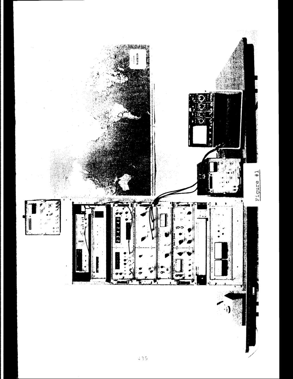
5 performance for a manual acquisition receiver rmally would range from 5dB attenuation in a low signal level situation to as much as 99dB in a strong Loran-C source environment such as in the near field of a radiating transmitter. The approximate setting for the averaging time constant in a manual receiver directly determines the effective bandwidth of performance. A longer period of averaging will allow the receiver to capture more energy coherent with the Loran-C source and reject sources that do t contribute to making the time measurement. The equipment used to collect the baseline data is shown in Figure 1. The set up consists of both an automatic and manual Loran-C timing receiver; as well as all the ancillary equipment required to provide a comparison. Please also refer to Figure 2 for the geographical features of paths to Austin. I 1 The propagation paths into Austin, Texas that were used to collect data ranged from a 2665 kilometers path with a radiated power of 1.6 megawatt over a stressful total land path to a 438 kilometer path from a nearby transmitter radiating 400kW. In addition, observations were made at receiving sites in Washington, D.C., and at Patrick AFB to get additional path-type observations over various conditions. The two extremes for long path measurements dealt with a path length of 2700 kilometers over mountain and rocky terrain. Total attenuation expected over this path is well over 100 db. Please refer to Chart 2 for received signal levels and identification of propagation path properties.
6 LORAN-C CONDUCTIV f TY CHART k STATION TR'ANSM I TTED POWER DISTA CE (4 CONDUCTIVITY/TYPE OF PATH RECEIVED POWER p ~ RAYMONDVILLE 400kW 438 GOOD/Sandy Loam Soil GRANGEVI LLE 800kW 680 GOOD/Sandy Loam Soil MALONE 800kW 1215 GOOD/Sandy Loam Soil JUPITER 275kW 1785 EXCELLENT/ 44% Seawater, 56% Sandy Loam 55.7 CAROLINE BEACH 5SOkW 1915 POOR/Mountains, Rocky Terrain 98.0 SENECA FALLS BOOkW 2335 POOR/Mountains, Rocky Terrain 96.0 DANA 400kW 1410 FAIR/Hilly Terrain BAUDETTE S20kW 2060 POOR/Rockey and Hilly Terrain 80.1 FALLON 400kW 2168 POOR/Moun tains And Rocky Terrain, Salt Flat 56.9 GEORGE 1.6MW 2565 POOR/Mountains, Rocky Terrain MIDDLETON 400kW 2460 POOR/Mountains, Rocky Terrain 44.1 SEAHCHL I GHT 500kW 1710 POORIHills and Rocky Terrain NANTUCKET 275kW 2775 POOR/Mountains, Rocky Terrain 24.0 Chart 12
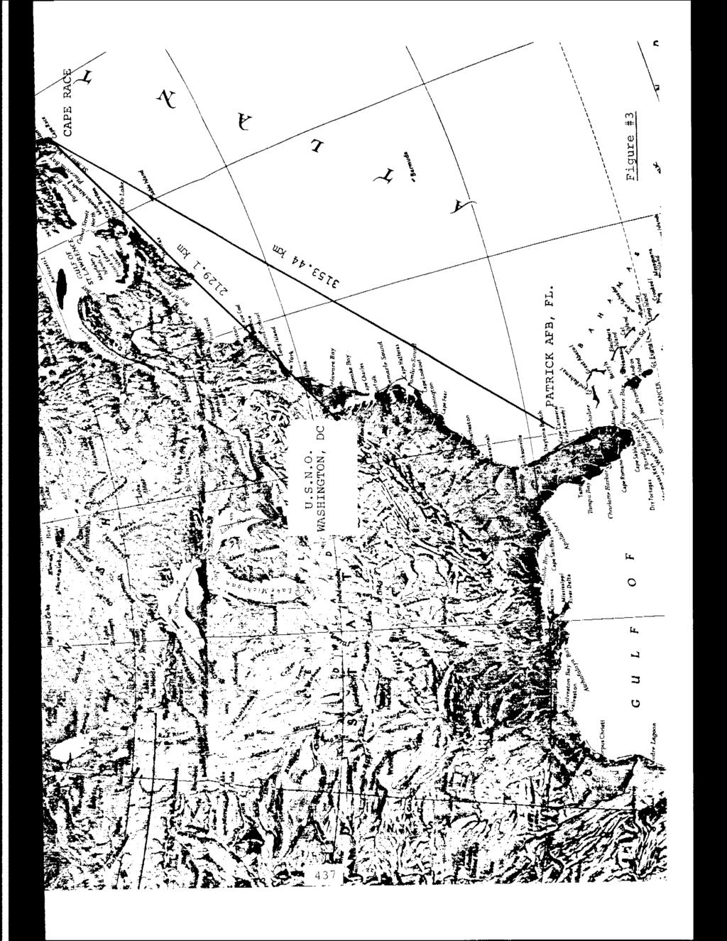
7 A long total sea water path of 3153kM was used to provide a test for receiver performance. A shorter path having a mixture of attenuation characteristics is the one from Cape Race, Newfoundland to Washington, D.C., 2129 km, and about half is over sea water. Attenu- ation over this type of path would be expected to be under 90 db. Please refer to Figure 3 for geographi- cal features. The resultant performance of these paths is shown in Chart 3. The accuracy of the Loran-C timing measurement is traceable to the synchronization of the Loran-C transmitter to the U.S. Naval Observatory null second pulse and thus UTC can be derived from the received pulse. The determination of accuracy is best when a solid groundwave signal is present. Under these conditions, a local ~ PPS can be developed to better than 1 microsecond with respect to UTC. As the distance from the transmitter to the observation point is increased, the potential for skywave contamination exists. As the distance becomes too large to sustain any groundwave measurement, the Loran-C skywave can be used to determine time but with degraded accuracy. The task of an operator of a Loran-C receiver is to maximize his potential to receive unambiguous groundwave and derive a lpps synchronization from it. BY virtue of the pulse-type of transmission from Lor an-c and the accurate synchronization of transmissions, it is practical to distinquish the groundwave propagated signal clearly from the skywave. The distance from the
8
9 transmitter for unambiguous groundwave reception is 1000kM. Skywave presence can become a significant in luence at distances greater than 1500kM. The technique for distinquishing groundwave reception has to do with the precise timing synchronization of the pulse transmission. please review Figure 4 to obtain a better appreciation of the actual observations recorded using a path length over which significant skywave signals are present. The operator of the manual Loran-C timing receiver must have a basic kwledge of electronic test equipment and an understanding of radio propagation. The test equipment required consists of a time interval counter, an oscilloscope and a strip chart recorder. The ancillary instruments required are a time-of-day clock, frequency source and possibly at long distances in isy areas, a synchrous filter and/or tch filter. The operator must first obtain a coarse clock synchronization to within 10 milliseconds of UTC by a reference timing signal such as WWV or WwVB. The operator then sets the time-of-day clock to the reference, selects a Loran-C station and accomplishes acquisition. The most difficult step of Loran-C time recovery is to recognize and lock onto the correct tracking point. This is complicated by low signal to ise conditions. The degree of operator skill required to operate the manual Loran-C timing receiver is inversely proportional to the received Loran-C signal strength, the amount of radio-frequency-interference (RFI), and the ise level. These factors also determine the amount and type of
10 ancillary instruments to achieve proper identification and tracking of the received pulse. The manual operator with minimum skill, within loookm of the transmitter of interest and in a relative low ise area will achieve desired results in a short period of time with minimum ancillary instruments. A hostile radio-frequency environment, where the pulse strength is below that of the ise and/or RFI levels, requires the operator to be a very experienced user of Loran-C timing reception techniques and proficient in the use of various ancillary instruments. An automatic receiver that will provide the desired results in both environments reduces the operator skill level required, the operator time involved, and makes a significant decrease in the quantity and type of ancillary instruments required to achieve the acquisition and final tracking of the desired Loran-C pulse. DESIGN GOALS The first goal to address in the design of an auto- matic acquisition receiver is sensitivity. The receiver must adequately amplify a minimum usable signal level of.o1 microvolts RMS to the level required by the acquisition and tracking hardware. An additional consideration is band pass filtering. The requirement is to exclude RF energy outside the required information bandwidth of the Loran-C signal, Since any band pass filter limits the faithful reproduction of the input signal while improving the ise performance, the design task is to select the proper bandwidth to optimize performance and obtain the best ise rejection. A
11 narrow BW for acquisition and a wider BW for precise phase tracking are needed and identified as objectives for the design activity. Gain must be automatically adjustable over the entire dynamic range of operation. This allows auto- matic selection of the optimum level. In view of the wide variation of propagation conditions, rmally observed in long path monitoring of Loran-C transmissions, a decision was made to use an automatic adjustment by a microprocessor system. This concept allows for optimum tracking of the incoming signal in dynamic signal to ise situations. An additional design feature is the use of numerical averaging of the Loran-C signal received to seduce the effects of n-coherent ise and CW interference. The goal for numerical processing of the signal is to improve performance over a manual receiver by 15 db or more. The operation of an automatic acquisition Loran-C timing receiver should t require special skills or training of the operator. Ancillary equipment should t be required other than to provide a IPPS coarse time source to within 10 ms of UTC for initial synchronization programmable operations from a remote location are desirable. A standard reference frequency to at least an accuracy of 1 x lom8 is required. A very important design goal of the automatic system is to identify a11 acquirable Loran-C signals at the selected transmission rate and to establish the most acquirable one. Design decisions were made to use correlation techniques with a narrow band pass filter
12 (4 khz bandwidth) and hard limit the RF sampled at a period of 100 microseconds over one transmission frame. The process allows for all usable signals to be identified and graded as to their signal to ise property and represented by quantitative correlation numbers. Subsequent sampling at a wider bandwidth operates on the most desirable stations to identify the proper cycle upon which to make the measurement of coincidence with respect to the Loran-C transmissions. ~uch care has been taken in the selection of the time constants that control the digital servo loops and which establish the effective bandwidth of the receiving system. The design approach here is to provide an adaptive time constant which is automatically controlled by the signal to ise ratio. Once the loop error is sufficiently small the receiver goes into a track mode. At this time, the servo system is ready for synchronization with a null second from the Loran-C transmitter. Additional factors to be considered in the design of an automatic acquisition Loran-C receiver are size, weight, power, cost, reliability, and maintainability. The size selected was the smallest rack-mountable size consistant with proper attention to human factors; such as push button size, observable display and legend readability. The weight and power were minimized by use of large scale in- tegrated circuits and a switching power supply. Reliability was enhanced through use of LSI parts and long lifetime components, The maintainability of the unit is insured by the use of plug in cards with universal bus structure where possible, built in test routines with
13 signature analysis, and flip open front panel fox easy access to components. Replaceable software allows for future improvements and additions to the capabilities. Optional remote control capability through the IEEE-488 interface is available for installations requiring remote or fully automated operation. MEASURED PARAMETERS Chart # 4 summarizes differences between automatic and manual receivers. The key features which permit successful operation in a hostile signal to ise environmnet are automatic gain control and adaptive signal to ise control. The comparison test of the automatic Loran-C receiver with the manual one was conducted through the use of a relatively inexperienced University of Texas electrical engineering student who was hired specifically to operate the equipment. He had previous operational experience with low frequency radio propagation or with precise time determination equipment using Loran-C transmission. The key items for making this comparison are acquisition time, operator attention, need to employ a synchrous filter, variation of measured delay, and a relative signal to ise indication. See Chart #5 for data summary. The significance of operator attention and acquisition time for the different receivers may be too subtle to be clearly obvious. The major point in recording the time data here is to emphasize the lack of constant operator attention needed by the automatic receiver. In the case of
14 NUAl vs AUTOMAT I C PARAMETERS AUTOMATIC SENSITIVITY GAIN RANGE AUTOMATIC GAIN CONTROL BANDWIDTH Acquisition: 5 kila Tracking: 20/50 khz.olijvrms db Yes 4 khz 40 khz AVERAGING TIME CONSTANT TRACKING POINT TIME OF COINCIDENCE SYNCHRONI ZATION OPERATOR SKILL AND ATTENTION REQUIRED ANCILLARY EQUIPMENT REQUIRED REMOTE CONTROL OPTION Selectable Slewable-. lps Res. Manual High Oscilloscope Time Interval Counter Coarse Time Source (UTC) 1 MHz Freq. Ref. Strip Chart Recorder Synchrous Filter Time of Day Clock None Adaptive Automatic Low N/A N/ A Coarse Time Source (UTC) 1, 5, or 10 MHz Ref. N/A Included Included IEEE I Chart #4

15 v 7 STAT1 ON SYSTEM RECEIVFD S-GNAL MEASURED AUXILIARY ACQUISITION OPERATOR AH RF NOISE 3- DELAYS EQUIPMENT TI ME ATTENTI ON mvp-p mvp-p SF usfc MYMONDVILLE GRANGEVI LLE MALON E JUPITER CARLOL I NE BEACH DANA 4 W w SENECA FALLS BAUDETTE NANTUCKET GEORGE FALLON Manua 1 Automatic Manual Automatic Manual Automatic Manual Automatic Manua 1 Automatic Manual Automatic Manual Automatic Manua 1 Automatic Manual Automa tlc Manual Autornatlc Manual Automatic Zj I 21dB 2 0dB 2 0dB 2 1dB 16dB 16dB 2 db 2dB -3.8dB -3.8d3 8.4dB 8.4dB dB I -50dB 1,394, 80-46dB dB r I -5CilB 75, -50dB I 80-42dB 80-42d3 I I -45dB! -45dB SEARCHLIGHT Manual dB Yes 45 min. 45 min. Automa tic dB mln. 10 min. MIDDLETON Manual.I dB Yes 1 hr. 45 min. 1 hr. 45 min. Automatic.I dB rnin. 15 min. NOTE: OPERATOR SKILL - Four hours of training on each receiver system just prior to start of test. Yes Yes yes 10 mln. 5 min. 15 rnin. 8 min. 17 min. 6 min. 20 min. 10 min. 45 min. 20 min. llhr. 30rnin. 30 min Yes 1 1 hr. 30 min mln Yes I Yes I 50 min. 20 rnin. 45 min. 15 mln. 1 hr. 45 min. 45 min, 2 hrs. 45 min. 10 min. 3 min. 5 min. 5 min. 17 min. 4 min. 20 min. 5 min. 50 min. 5 min. 45 min. 5 min. 45 min. 8 min. 1hr. 30min. 15 min. 1 hr. 30 min. 15 min. 1 hr. 45 min. 15 min. 2 hrs. 15 min.
16 Seneca Falls, the time to acquire for an automatic receiver was 20 minutes as compared to 45 minutes for the manual receiver. On the other hand, the operator attention time was reduced from 45 minutes to 8 minutes. The data collected from Raymondville, Texas indicated a very stong signal of 820 millivolts. Either technique required a minimum amount of acquisition time and similar operator attention spans. The worst case condition for time to acquire was ted in the signal from Fallon, Nevada which, at the peak cycle, measured only 430 microvolts, showing a signal difference of 66 db. In this situation, the manual receiver required the use of the synchrous filter and took 2 hours of acquisition time and constant operator attention. The automatic receiver made the measurement in 45 minutes and took 15 minutes of operator attention. The best performance using the manual receiver unaided by the synchrous filter was monitoring Jupiter, Florida. The acquisition and operator attention required using the manual, receiver was 20 minutes. The automatic receiver performed the task in 10 minutes and required only 5 minutes of operator attention. The variation of measured delay between the automatic receiver and the manual one was never any greater than 0.9 microsecond in the range of data collected. The difference between the two measurements had a standard deviation of 0.22 microseconds and a mean value of 0.66 microseconds. In addition, it should be ted that the synchrous filter was necessary to complete the time measurement using the
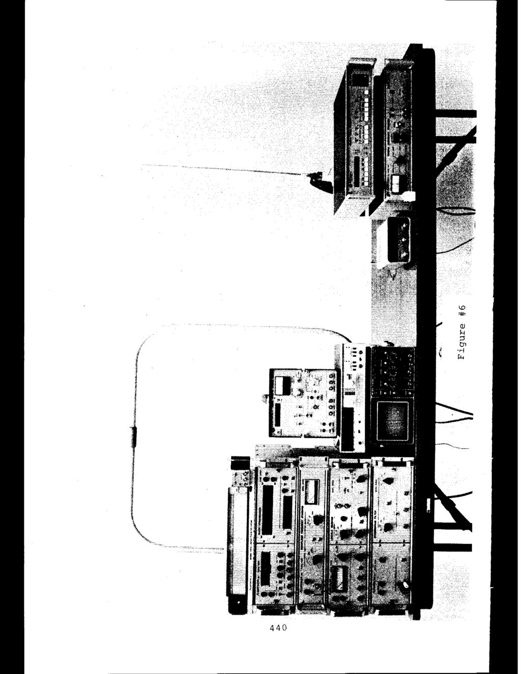
17 manual receiver in eight out of the 13 transmitters moni- tored and that operator attention in these situations using the automatic receiver was never longer than 15 minutes. SUMMARY AND CONCLUSIONS The present manual system of precise time determination uses a number of ancillary items and operator assist devices to accomplish a time measurement to an accuracy of one micro- second. Please refer to Figure 5 for a view of the total manual system. The large variety of propagation conditions, ise environment and long range potential possible with Loran-C make an automatic microprocessor controlled receiver a very desirable instrument. We have attempted to show clear evidence of reception success over a wide range of conditions using an automatic Loran-C timing receiver. Please see Figure 6 for a comparison of the relative complexity of automatic instrumentation versus manual. A key factor demonstrated in the measurements is the reduction in operator attention. Demonstrated differences show a reduction of operator attention from 2 hours to 15 minutes for the worst case situation. I I A good ground wave time measurement was made to better than one microsecond of UTC over a sea water path of length of 3153 kilometers from a 1.8 meqawatt transmitter and over a land path of length of 2665 kilometers from a 1.6 meqawatt transmitter using the automatic receiver.
18 One of the most serious operational complications that arisesin establishing an accurate time using Loran-C is the ability to deal with the skywave presence at long ranges from the transmitter. The automatic receiver has successfully detected and made an accurate time measurement in the presence of skywave signals more than 20 d~ greater than ground wave.
19

20
21
22 RECORDING OF RECEIVED LORAN-C SIGNAL TRANSMITTER: George, Washington TDTNSMITTER POWER: 1.6 MW PATH DISTANCE: 2665 KM TIME OF RECORDING: 0300 Hours UTC 9:00 PM Local RECEIVER SITE: AUSTIN, TEXAS TYPE RECEIVER SYSTEM: Manual Receiver with Ancillary instruments. NOTES : (1) Groundwave (2) First Hop (3) Second Hop Fiqure #4

23
24
25 QUESTIONS AND ANSWERS DR. WINKLER: You mentioned that your receiver has the IEEE 488 bus capability. I just wonder whether you can increase that time that you have listed of eight minutes, or so by simply connecting it to a control 1 er. MR. PRICE: That is right. If it is remotely programmable and can be controlled from a mobile location, you can replace the person sitting there watching it. Yes? MR. BANERGEE: How is this table system going to in~prove the performance? MR. PRICE: I think your question is will this receiver improve the performance of capturing the ground wave in the face of the sky wave? I 1 Is that the question? MR. BAliRtii: The question is that we can't receive the ground wave because we are out of the range. MR. PRICE: Well, how far out is your distance? are you like 2,000 kilometers? P,re you like 1,500 kilometers, 1 MR. BANERGEE : More than 1,500 kilometers. MR. PRICE: More than 1,500 ki 1 ometers? 42 1
26 MR. BANERGEE: Much more than 1,500 kilometers. MR. PRICE: I think probably in that case you might just have too much attenuation to get a significant ground wave and you may need to make a sky wave measurement. What is your accuracy requirements for time? MR. BANERGEE: I would like to kw how we could receive these with this type of receiver? MR. PRICE: Okay, if we were using a sky wave signal which we didn't talk about using a measurement because I would rather use a ground wave, we can probably get about 50 microseconds accuracy. UTC, within 50 microseconds, if you are using the ground wave you might expect to get within a microsecond. MR. BANERJEE : Thank you. MR. JERRY PUNT, Interstate Electronics What is the difference between the 15 minutes of operator time and the 8 minutes of operator time in this function? MR. PRICE: Jerry, either the signal-to-ise environment is tougher where :you take a little longer period of time, or it might just be it has some trouble sorting out the sky wave from the ground wave because of the particular distance that you are from the transmitter. We haven't really analyzed exactly why those figure differences are there, but I think that all of those factors bear on the amount of time a receiver takes to make a measurement. MR. PUNT: I understand the receiver time, but what about the operator time, what does the operator have to do that this requires 15 minutes in certain cases and only 8 minutes in ather case?
27 MR. PRICE: Sometimes he has to just wait for ather TOC, because there is 15 minutes separation between TOC on some of the chains. Time of Coincidence is what the Naval Observatory calls it. PROFESSOR LESCHIUTTA: Just for my information I would like to kw if using the IEEE bus, could we possibly give instruction to the receiver in order to study at one time the ground wave and at some other time the sky way; or perhaps the instruction to the receiver that always tries to get the first signal, the ground signal? MR. PRICE: My answer is that that is t rmally the way we would expect it to be programmed. With the flexibility that we have we could work with you and hopefully we could make some arrangements to do some of those things.
A NEW GENERATION PROGRAMMABLE PHASE/AMPLITUDE MEASUREMENT RECEIVER
 GENERAL A NEW GENERATION PROGRAMMABLE PHASE/AMPLITUDE MEASUREMENT RECEIVER by Charles H. Currie Scientific-Atlanta, Inc. 3845 Pleasantdale Road Atlanta, Georgia 30340 A new generation programmable, phase-amplitude
2015 Interference 101. Robin Jackman Application Engineer
 2015 Interference 101 Robin Jackman Application Engineer Agenda What is Interference Introduction Definitions Spectrum Analyzer Concepts Concepts, Controls, Displays Making good measurements Measuring
Design of Simulcast Paging Systems using the Infostream Cypher. Document Number Revsion B 2005 Infostream Pty Ltd. All rights reserved
 Design of Simulcast Paging Systems using the Infostream Cypher Document Number 95-1003. Revsion B 2005 Infostream Pty Ltd. All rights reserved 1 INTRODUCTION 2 2 TRANSMITTER FREQUENCY CONTROL 3 2.1 Introduction
satellite terminals. Mr. Murray is with the Time and Frequency Systems Unit, Naval Research Laboratory, Washington, D.C.
 MN MODEM FOR PTT DSSEMNATON by J. A. Murray, Jr. Mr. Murray is with the Time and Frequency Systems Unit, Naval Research Laboratory, Washington, D.C. Precise comparisons of clocks are now regularly made
Using Frequency Diversity to Improve Measurement Speed Roger Dygert MI Technologies, 1125 Satellite Blvd., Suite 100 Suwanee, GA 30024
 Using Frequency Diversity to Improve Measurement Speed Roger Dygert MI Technologies, 1125 Satellite Blvd., Suite 1 Suwanee, GA 324 ABSTRACT Conventional antenna measurement systems use a multiplexer or
DSTS-3B DEPTHSOUNDER TEST SET OPERATOR S MANUAL
 Page 1 1.0 INTRODUCTION DSTS-3B DEPTHSOUNDER TEST SET OPERATOR S MANUAL The DSTS-3B is a full-featured test set designed for use with all types of echo sounders from small flashers to large commercial
Screening Attenuation When enough is enough
 Screening Attenuation When enough is enough Anders Møller-Larsen, Ph.D. M.Sc. E.E. Product Manager, Coax Network Introduction This white paper describes the requirements to screening attenuation of cables
Module 8 Theory. dbs AM Detector Ring Modulator Receiver Chain. Functional Blocks Parameters. IRTS Region 4
 Module 8 Theory dbs AM Detector Ring Modulator Receiver Chain Functional Blocks Parameters Decibel (db) The term db or decibel is a relative unit of measurement used frequently in electronic communications
PRODUCT DEMODULATION - SYNCHRONOUS & ASYNCHRONOUS
 PRODUCT DEMODULATION - SYNCHRONOUS & ASYNCHRONOUS INTRODUCTION...98 frequency translation...98 the process...98 interpretation...99 the demodulator...100 synchronous operation: ω 0 = ω 1...100 carrier
Federal Communications Commission Office of Engineering and Technology Laboratory Division
 April 9, 2013 Federal Communications Commission Office of Engineering and Technology Laboratory Division Guidance for Performing Compliance Measurements on Digital Transmission Systems (DTS) Operating
Antenna Measurements using Modulated Signals
 Antenna Measurements using Modulated Signals Roger Dygert MI Technologies, 1125 Satellite Boulevard, Suite 100 Suwanee, GA 30024-4629 Abstract Antenna test engineers are faced with testing increasingly
Providing a Resilient Timing and UTC Service Using eloran in the United States. Charles Schue - ION PTTI Monterey, CA
 Providing a Resilient Timing and UTC Service Using eloran in the United States Charles Schue - ION PTTI Monterey, CA January 27, 2016 Motivation For a Resilient Timing and UTC Service GPS/GNSS Vulnerabilities
CH85CH2202-0/85/ $1.00
 SYNCHRONIZATION AND TRACKING WITH SYNCHRONOUS OSCILLATORS Vasil Uzunoglu and Marvin H. White Fairchild Industries Germantown, Maryland Lehigh University Bethlehem, Pennsylvania ABSTRACT A Synchronous Oscillator
Agilent 8902A Measuring Receiver
 Agilent 8902A Measuring Receiver Technical Specifications Agilent 11722A Sensor Module Agilent 11792A Sensor Module Agilent 11793A Microwave Converter Agilent 11812A Verification Kit The Agilent Technologies
Advances in Antenna Measurement Instrumentation and Systems
 Advances in Antenna Measurement Instrumentation and Systems Steven R. Nichols, Roger Dygert, David Wayne MI Technologies Suwanee, Georgia, USA Abstract Since the early days of antenna pattern recorders,
Potential interference from spaceborne active sensors into radionavigation-satellite service receivers in the MHz band
 Rec. ITU-R RS.1347 1 RECOMMENDATION ITU-R RS.1347* Rec. ITU-R RS.1347 FEASIBILITY OF SHARING BETWEEN RADIONAVIGATION-SATELLITE SERVICE RECEIVERS AND THE EARTH EXPLORATION-SATELLITE (ACTIVE) AND SPACE RESEARCH
HP 8901B Modulation Analyzer. HP 11722A Sensor Module. 150 khz MHz. 100 khz MHz. Technical Specifications. Four Instruments In One
 HP 8901B Modulation Analyzer 150 khz - 1300 MHz HP 11722A Sensor Module 100 khz - 2600 MHz Technical Specifications Four Instruments In One RF Power: ±0.02 db instrumentation accuracy RF Frequency: 10
Technician License Course Chapter 3 Types of Radios and Radio Circuits. Module 7
 Technician License Course Chapter 3 Types of Radios and Radio Circuits Module 7 Radio Block Diagrams Radio Circuits can be shown as functional blocks connected together. Knowing the description of common
Keysight Technologies Pulsed Antenna Measurements Using PNA Network Analyzers
 Keysight Technologies Pulsed Antenna Measurements Using PNA Network Analyzers White Paper Abstract This paper presents advances in the instrumentation techniques that can be used for the measurement and
Modernized LORAN-C Timing Test Bed Status and Results
 Modernized LORAN-C Timing Test Bed Status and Results Tom Celano and Casey Biggs Timing Solutions Corporation 4775 Walnut St Boulder, CO tpcelano@timing.com Benjamin Peterson Peterson Integrated Positioning
GSM Transmitter Modulation Quality Measurement Option
 Performs all required measurements for GSM transmitters Outputs multiple time mask parameters for process control analysis Obtains frequency error, rms phase error, and peak phase error with one command
MITIGATING INTERFERENCE ON AN OUTDOOR RANGE
 MITIGATING INTERFERENCE ON AN OUTDOOR RANGE Roger Dygert MI Technologies Suwanee, GA 30024 rdygert@mi-technologies.com ABSTRACT Making measurements on an outdoor range can be challenging for many reasons,
HF Time of Arrival Project
 HF Time of Arrival Project Joe Taylor, K1JT February 22, 2011 This progress report describes recent work on a project outlined on the AA6E web site. Martin Ewing (AA6E) and I have been conducting experiments
Sideband Smear: Sideband Separation with the ALMA 2SB and DSB Total Power Receivers
 and DSB Total Power Receivers SCI-00.00.00.00-001-A-PLA Version: A 2007-06-11 Prepared By: Organization Date Anthony J. Remijan NRAO A. Wootten T. Hunter J.M. Payne D.T. Emerson P.R. Jewell R.N. Martin
LIMITATION OF GPS RECEIVER CALIBRATIONS
 LIMITATION OF GPS RECEIVER CALIBRATIONS G. Paul Landis SFA, Inc./Naval Research Laboratory 4555 Overlook Ave., S.W. Washington, D.C. 20375, USA Tel: (202) 404-7061; Fax: (202) 767-2845 E-Mail: landis@juno.nrl.navy.mil
Digital Audio Broadcasting Eureka-147. Minimum Requirements for Terrestrial DAB Transmitters
 Digital Audio Broadcasting Eureka-147 Minimum Requirements for Terrestrial DAB Transmitters Prepared by WorldDAB September 2001 - 2 - TABLE OF CONTENTS 1 Scope...3 2 Minimum Functionality...3 2.1 Digital
PM 6669 High-Precision Frequency Counter Specifications
 PM 6669 High-Precision Frequency Counter Specifications Product Home Features Specifications Models, Options & Accessories Measuring functions Definitions Input specifications Auxiliary functions TimeBase
Digital Sounder: HF Diagnostics Module:Ionosonde Dual Channel ( ) Eight Channel ( )
 Eight Channel ( )") CENTER FOR REMOTE SE NSING, INC. Digital Sounder: HF Diagnostics Module:Ionosonde Dual Channel (001-2000) Eight Channel (004-2006) 2010 Center for Remote Sensing, Inc. All specifications subject to change
CENTER FOR REMOTE SE NSING, INC. Digital Sounder: HF Diagnostics Module:Ionosonde Dual Channel (001-2000) Eight Channel (004-2006) 2010 Center for Remote Sensing, Inc. All specifications subject to change
EET 223 RF COMMUNICATIONS LABORATORY EXPERIMENTS
 EET 223 RF COMMUNICATIONS LABORATORY EXPERIMENTS Experimental Goals A good technician needs to make accurate measurements, keep good records and know the proper usage and limitations of the instruments
Active Radio Frequency Sensing for Soil Moisture Retrieval
 Active Radio Frequency Sensing for Soil Moisture Retrieval T. Pratt and Z. Lin University of Notre Dame Other Contributors L. Leo, S. Di Sabatino, E. Pardyjak Summary of DUGWAY Experimental Set-Up Deployed
1 Minimum usable field strength
 1 RECOMMENDATION ITU-R BS.412-8* PLANNING STANDARDS FOR FM SOUND BROADCASTING AT VHF (Questions ITU-R 74/1 and ITU-R 11/1) (1956-1959-1963-1974-1978-1982-1986-199-1994-1995-1998) The ITU Radiocommunication
RECOMMENDATION ITU-R BS.80-3 * Transmitting antennas in HF broadcasting
 Rec. ITU-R BS.80-3 1 RECOMMENDATION ITU-R BS.80-3 * Transmitting antennas in HF broadcasting (1951-1978-1986-1990) The ITU Radiocommunication Assembly, considering a) that a directional transmitting antenna
SPECTRACOM MODEL 8165 DISCIPLINED OSCILLATOR ANTENNA INSTALLATION TABLE OF CONTENTS
 SPECTRACOM MODEL 8165 DISCIPLINED OSCILLATOR ANTENNA INSTALLATION TABLE OF CONTENTS Page 1.0 INTRODUCTION... 1 1.3 MODEL 8206A LOOP ANTENNA... 1 1.4 MODEL 8208 WHIP ANTENNA... 4 1.5 ANTENNA LOCATION...
SEQUENTIAL NULL WAVE Robert E. Green Patent Pending
 SEQUENTIAL NULL WAVE BACKGROUND OF THE INVENTION [0010] Field of the invention [0020] The area of this invention is in communication and wave transfer of energy [0030] Description of the Prior Art [0040]
EXHIBIT 7: MEASUREMENT PROCEDURES Pursuant 47 CFR 2.947
 EXHIBIT 7: MEASUREMENT PROCEDURES Pursuant 47 CFR 2.947 7.1 RF Power -- Pursuant to 47 CFR 2.947(c) Method of Conducted Output Power Measurement: Adaptation of TIA/EIA-603-A clause 2.2.1 for Pulsed Measurements
RECOMMENDATION ITU-R F Characteristics of HF fixed radiocommunication systems
 Rec. ITU-R F.1761 1 RECOMMENDATION ITU-R F.1761 Characteristics of HF fixed radiocommunication systems (Question ITU-R 158/9) (2006) Scope This Recommendation specifies the typical RF characteristics of
MAKING TRANSIENT ANTENNA MEASUREMENTS
 MAKING TRANSIENT ANTENNA MEASUREMENTS Roger Dygert, Steven R. Nichols MI Technologies, 1125 Satellite Boulevard, Suite 100 Suwanee, GA 30024-4629 ABSTRACT In addition to steady state performance, antennas
Performance of the Prototype NLC RF Phase and Timing Distribution System *
 SLAC PUB 8458 June 2000 Performance of the Prototype NLC RF Phase and Timing Distribution System * Josef Frisch, David G. Brown, Eugene Cisneros Stanford Linear Accelerator Center, Stanford University,
Emission Measurement Results for a Cellular and PCS Signal-Jamming Transmitter Frank H. Sanders Robert T. Johnk Mark A. McFarland J.
 NTIA Report TR-10-465 Emission Measurement Results for a Cellular and PCS Signal-Jamming Transmitter Frank H. Sanders Robert T. Johnk Mark A. McFarland J. Randall Hoffman NTIA Report TR-10-465 Emission
ECC Recommendation (16)04
04") ECC Recommendation (16)04 Determination of the radiated power from FM sound broadcasting stations through field strength measurements in the frequency band 87.5 to 108 MHz Approved 17 October 2016 Edition
ECC Recommendation (16)04 Determination of the radiated power from FM sound broadcasting stations through field strength measurements in the frequency band 87.5 to 108 MHz Approved 17 October 2016 Edition
Frequency Agility and Barrage Noise Jamming
 Exercise 1-3 Frequency Agility and Barrage Noise Jamming EXERCISE OBJECTIVE To demonstrate frequency agility, a radar electronic protection is used against spot noise jamming. To justify the use of barrage
3.2 Measuring Frequency Response Of Low-Pass Filter :
 2.5 Filter Band-Width : In ideal Band-Pass Filters, the band-width is the frequency range in Hz where the magnitude response is at is maximum (or the attenuation is at its minimum) and constant and equal
An Introduction to Spectrum Analyzer. An Introduction to Spectrum Analyzer
 1 An Introduction to Spectrum Analyzer 2 Chapter 1. Introduction As a result of rapidly advancement in communication technology, all the mobile technology of applications has significantly and profoundly
FM Transmission Systems Course
 FM Transmission Systems Course Course Description An FM transmission system, at its most basic level, consists of the transmitter, the transmission line and antenna. There are many variables within these
Narrow- and wideband channels
 RADIO SYSTEMS ETIN15 Lecture no: 3 Narrow- and wideband channels Ove Edfors, Department of Electrical and Information technology Ove.Edfors@eit.lth.se 27 March 2017 1 Contents Short review NARROW-BAND
POLISH MARITIME DGPS REFERENCE STATIONS COVERAGE AFTER THE IMPLEMENTATION OF NEW FREQUENCY NET PRELIMINARY RESULTS.
 POLISH MARITIME DGPS REFERENCE STATIONS COVERAGE AFTER THE IMPLEMENTATION OF NEW FREQUENCY NET PRELIMINARY RESULTS. Cezary Specht Institute of Navigation and Hydrography of Naval University in Gdynia ABSTRACT
Dartmouth College LF-HF Receiver May 10, 1996
 AGO Field Manual Dartmouth College LF-HF Receiver May 10, 1996 1 Introduction Many studies of radiowave propagation have been performed in the LF/MF/HF radio bands, but relatively few systematic surveys
Keysight Technologies PNA-X Series Microwave Network Analyzers
 Keysight Technologies PNA-X Series Microwave Network Analyzers Active-Device Characterization in Pulsed Operation Using the PNA-X Application Note Introduction Vector network analyzers (VNA) are the common
Industrial Wireless Systems
 Application Considerations Don Pretty Principal Engineer Geometric Controls Inc Bethlehem, PA Sheet 1 Ethernet Dominates on the Plant Floor Sheet 2 Recognize Any of These? Sheet 3 Answers: 10 BASE 2 RG
Keysight Technologies Essential Capabilities of EMI Receivers. Application Note
 Keysight Technologies Essential Capabilities of EMI Receivers Application Note Contents Introduction... 3 CISPR 16-1-1 Compliance... 3 MIL-STD-461 Compliance... 4 Important features not required by CISPR
ECE 476/ECE 501C/CS Wireless Communication Systems Winter Lecture 6: Fading
 ECE 476/ECE 501C/CS 513 - Wireless Communication Systems Winter 2003 Lecture 6: Fading Last lecture: Large scale propagation properties of wireless systems - slowly varying properties that depend primarily
Utilizzo del Time Domain per misure EMI
 Utilizzo del Time Domain per misure EMI Roberto Sacchi Measurement Expert Manager - Europe 7 Giugno 2017 Compliance EMI receiver requirements (CISPR 16-1-1 ) range 9 khz - 18 GHz: A normal +/- 2 db absolute
LOW POWER GLOBAL NAVIGATION SATELLITE SYSTEM (GNSS) SIGNAL DETECTION AND PROCESSING
 SIGNAL DETECTION AND PROCESSING") LOW POWER GLOBAL NAVIGATION SATELLITE SYSTEM (GNSS) SIGNAL DETECTION AND PROCESSING Dennis M. Akos, Per-Ludvig Normark, Jeong-Taek Lee, Konstantin G. Gromov Stanford University James B. Y. Tsui, John Schamus
LOW POWER GLOBAL NAVIGATION SATELLITE SYSTEM (GNSS) SIGNAL DETECTION AND PROCESSING Dennis M. Akos, Per-Ludvig Normark, Jeong-Taek Lee, Konstantin G. Gromov Stanford University James B. Y. Tsui, John Schamus
Lecture 6 SIGNAL PROCESSING. Radar Signal Processing Dr. Aamer Iqbal Bhatti. Dr. Aamer Iqbal Bhatti
 Lecture 6 SIGNAL PROCESSING Signal Reception Receiver Bandwidth Pulse Shape Power Relation Beam Width Pulse Repetition Frequency Antenna Gain Radar Cross Section of Target. Signal-to-noise ratio Receiver
03_57_104_final.fm Page 97 Tuesday, December 4, :17 PM. Problems Problems
 03_57_104_final.fm Page 97 Tuesday, December 4, 2001 2:17 PM Problems 97 3.9 Problems 3.1 Prove that for a hexagonal geometry, the co-channel reuse ratio is given by Q = 3N, where N = i 2 + ij + j 2. Hint:
Longer baselines and how it impacts the ALMA Central LO
 Longer baselines and how it impacts the ALMA Central LO 1 C. Jacques - NRAO October 3-4-5 2017 ALMA LBW Quick overview of current system Getting the data back is not the problem (digital transmission),
Sensitivity of Series Direction Finders
 Sensitivity of Series 6000-6100 Direction Finders 1.0 Introduction A Technical Application Note from Doppler Systems April 8, 2003 This application note discusses the sensitivity of the 6000/6100 series
Application Report. Art Kay... High-Performance Linear Products
 Art Kay... Application Report SBOA0A June 2005 Revised November 2005 PGA309 Noise Filtering High-Performance Linear Products ABSTRACT The PGA309 programmable gain amplifier generates three primary types
AUR.EL RTX-MID-868-OOK DESCRIPTION. MECHANICAL DIMENSIONS and PIN-OUT. Absolute maximum values
 DESCRIPTION RTX-MID-868 is RF digital transceiver working at 868,3MHz with FSK and OOK modulation. The main features are: 10 mw Maximum of effective irradiated power, - 108 dbm of sensitivity in FSK and
RECOMMENDATION ITU-R SA Protection criteria for deep-space research
 Rec. ITU-R SA.1157-1 1 RECOMMENDATION ITU-R SA.1157-1 Protection criteria for deep-space research (1995-2006) Scope This Recommendation specifies the protection criteria needed to success fully control,
FREQUENCY AGILE FM MODULATOR INSTRUCTION BOOK IB
 FMT615C FREQUENCY AGILE FM MODULATOR INSTRUCTION BOOK IB1215-02 TABLE OF CONTENTS SECTION SUBJECT 1.0 Introduction 2.0 Installation & Operating Instructions 3.0 Specification 4.0 Functional Description
Synchronous Communications
 Synchronous Communications JOHN P. COSTAS Classic Paper It can be shown that present usage of amplitude modulation does not permit the inherent capabilities of the modulation process to be realized. In
DAC A (VCO) Buffer (write) DAC B (AGC) Buffer (write) Pulse Code Buffer (write) Parameter Buffer (write) Figure A.1. Receiver Controller Registers
 Buffer (write) DAC B (AGC) Buffer (write) Pulse Code Buffer (write) Parameter Buffer (write) Figure A.1. Receiver Controller Registers") Appendix A. Host Computer Interface The host computer interface is contained on a plug-in module designed for the IBM PC/XT/AT bus. It includes the converters, counters, registers and programmed-logic
Appendix A. Host Computer Interface The host computer interface is contained on a plug-in module designed for the IBM PC/XT/AT bus. It includes the converters, counters, registers and programmed-logic
Code No: R Set No. 1
 Code No: R05220405 Set No. 1 II B.Tech II Semester Regular Examinations, Apr/May 2007 ANALOG COMMUNICATIONS ( Common to Electronics & Communication Engineering and Electronics & Telematics) Time: 3 hours
Data Conversion Circuits & Modulation Techniques. Subhasish Chandra Assistant Professor Department of Physics Institute of Forensic Science, Nagpur
 Data Conversion Circuits & Modulation Techniques Subhasish Chandra Assistant Professor Department of Physics Institute of Forensic Science, Nagpur Data Conversion Circuits 2 Digital systems are being used
10 Mb/s Single Twisted Pair Ethernet Noise Environment for PHY Proposal Evaluation Steffen Graber Pepperl+Fuchs
 10 Mb/s Single Twisted Pair Ethernet Noise Environment for PHY Proposal Evaluation Steffen Graber Pepperl+Fuchs IEEE P802.3cg 10 Mb/s Single Twisted Pair Ethernet Task Force 3/7/2017 1 Content Noise in
Optimizing 16 db Capture Effect to Overcome Class A 'Channelized' Signal Booster Group Delay problems within Public Safety Communications Systems
 Optimizing 16 db Capture Effect to Overcome Class A 'Channelized' Signal Booster Group Delay problems within Public Safety Communications Systems July 30, 2008 2008 Jack Daniel Company 2008 Jack Daniel
Rec. ITU-R F RECOMMENDATION ITU-R F *
 Rec. ITU-R F.162-3 1 RECOMMENDATION ITU-R F.162-3 * Rec. ITU-R F.162-3 USE OF DIRECTIONAL TRANSMITTING ANTENNAS IN THE FIXED SERVICE OPERATING IN BANDS BELOW ABOUT 30 MHz (Question 150/9) (1953-1956-1966-1970-1992)
Understanding Low Phase Noise Signals. Presented by: Riadh Said Agilent Technologies, Inc.
 Understanding Low Phase Noise Signals Presented by: Riadh Said Agilent Technologies, Inc. Introduction Instabilities in the frequency or phase of a signal are caused by a number of different effects. Each
HF Receivers, Part 2
 HF Receivers, Part 2 Superhet building blocks: AM, SSB/CW, FM receivers Adam Farson VA7OJ View an excellent tutorial on receivers NSARC HF Operators HF Receivers 2 1 The RF Amplifier (Preamp)! Typical
7. Transmitter Radiated Spurious Emissions and Conducted Spurious Emission
 7. Transmitter Radiated Spurious Emissions and Conducted Spurious Emission 7.1 Test Setup Refer to the APPENDIX I. 7.2 Limit According to 15.247(d), in any 100 khz bandwidth outside the frequency band
Model 855 RF / Microwave Signal Generator
 Features Very low phase noise Fast switching Phase coherent switching option 2 to 8 phase coherent outputs USB, LAN, GPIB interfaces Applications Radar simulation Quantum computing High volume automated
ELSEMA 1,2,3,4,8 -Channel 433MHz GIGALINK Transmitter GLT43300,GLT43301,GLT43302,GLT43303,GLT43304,GLT43308
 433MHz HAND HELD GIGALINK TRANSMITTERS GLT43300, GLT43301, GLT43302, GLT43303, GLT43304 and GLT43308 Features One, two, three, four & eight buttons. More than four billion code combinations Ability to
Chapter-1: Introduction
 Chapter-1: Introduction The purpose of a Communication System is to transport an information bearing signal from a source to a user destination via a communication channel. MODEL OF A COMMUNICATION SYSTEM
AN EXTENDED PHASE-LOCK TECHNIQUE FOR AIDED ACQUISITION
 AN EXTENDED PHASE-LOCK TECHNIQUE FOR AIDED ACQUISITION Item Type text; Proceedings Authors Barbour, Susan Publisher International Foundation for Telemetering Journal International Telemetering Conference
Chapter 2 Analog-to-Digital Conversion...
 Chapter... 5 This chapter examines general considerations for analog-to-digital converter (ADC) measurements. Discussed are the four basic ADC types, providing a general description of each while comparing
Essential Capabilities of EMI Receivers. Application Note
 Essential Capabilities of EMI Receivers Application Note Contents Introduction... 3 CISPR 16-1-1 Compliance... 3 MIL-STD-461 Compliance... 4 Important features not required by CISPR 16-1-1 or MIL-STD-461...
HP 8901B Modulation Analyzer. HP 11722A Sensor Module. 150 khz MHz. 100 khz MHz. Technical Specifications. Four Instruments In One
 HP 8901B Modulation Analyzer 150 khz - 1300 MHz HP 11722A Sensor Module 100 khz - 2600 MHz Technical Specifications Four Instruments In One RF Power: ±0.02 db instrumentation accuracy RF Frequency: 10
Wireless Channel Propagation Model Small-scale Fading
 Wireless Channel Propagation Model Small-scale Fading Basic Questions T x What will happen if the transmitter - changes transmit power? - changes frequency? - operates at higher speed? Transmit power,
ANALOG COMMUNICATION
 ANALOG COMMUNICATION TRAINING LAB Analog Communication Training Lab consists of six kits, one each for Modulation (ACL-01), Demodulation (ACL-02), Modulation (ACL-03), Demodulation (ACL-04), Noise power
Link Budget Calculation
 Link Budget Calculation Training materials for wireless trainers This 60 minute talk is about estimating wireless link performance by using link budget calculations. It also introduces the Radio Mobile
Sharing Considerations Between Small Cells and Geostationary Satellite Networks in the Fixed-Satellite Service in the GHz Frequency Band
 Sharing Considerations Between Small Cells and Geostationary Satellite Networks in the Fixed-Satellite Service in the 3.4-4.2 GHz Frequency Band Executive Summary The Satellite Industry Association ( SIA
EENG473 Mobile Communications Module 3 : Week # (12) Mobile Radio Propagation: Small-Scale Path Loss
 Mobile Radio Propagation: Small-Scale Path Loss") EENG473 Mobile Communications Module 3 : Week # (12) Mobile Radio Propagation: Small-Scale Path Loss Introduction Small-scale fading is used to describe the rapid fluctuation of the amplitude of a radio
EENG473 Mobile Communications Module 3 : Week # (12) Mobile Radio Propagation: Small-Scale Path Loss Introduction Small-scale fading is used to describe the rapid fluctuation of the amplitude of a radio
THE CO-EXISTENCE OF SPREAD SPECTRUM RANGING SIGNAL IN INDIAN NATIONAL SATELLITE-1B (INSAT-IB) WITH TV OR SCPC CHANNELS
 WITH TV OR SCPC CHANNELS") THE CO-EXISTENCE OF SPREAD SPECTRUM RANGING SIGNAL IN INDIAN NATIONAL SATELLITE-1B (INSAT-IB) WITH TV OR SCPC CHANNELS Item Type text; Proceedings Authors Lal, P.M.C.; Palsule, V.S.; Kumar, Pramod Publisher
THE CO-EXISTENCE OF SPREAD SPECTRUM RANGING SIGNAL IN INDIAN NATIONAL SATELLITE-1B (INSAT-IB) WITH TV OR SCPC CHANNELS Item Type text; Proceedings Authors Lal, P.M.C.; Palsule, V.S.; Kumar, Pramod Publisher
The Discussion of this exercise covers the following points:
 Exercise 3-2 Frequency-Modulated CW Radar EXERCISE OBJECTIVE When you have completed this exercise, you will be familiar with FM ranging using frequency-modulated continuous-wave (FM-CW) radar. DISCUSSION
Chapter 4 DOA Estimation Using Adaptive Array Antenna in the 2-GHz Band
 Chapter 4 DOA Estimation Using Adaptive Array Antenna in the 2-GHz Band 4.1. Introduction The demands for wireless mobile communication are increasing rapidly, and they have become an indispensable part
IEEE Wireless Access Method and Physical Layer Specification. Proposal For the Use of Packet Detection in Clear Channel Assessment
 IEEE 802.11 Wireless Access Method and Physical Layer Specification Title: Author: Proposal For the Use of Packet Detection in Clear Channel Assessment Jim McDonald Motorola, Inc. 50 E. Commerce Drive
Piezoelectric Discriminators
 Introduction Piezoelectric Discriminators Ceramic discriminators are designed to be used in quadrature detection circuits to remove a FM carrier wave. These circuits receive a FM signal, like in a FM radio,
Wideband Receiver Design
 Wideband Receiver Design Challenges and Trade-offs of a Wideband Tuning Range in Wireless Microphone Receivers in the UHF Television Band About this White Paper Professional wireless microphone systems
ECE 476/ECE 501C/CS Wireless Communication Systems Winter Lecture 6: Fading
 ECE 476/ECE 501C/CS 513 - Wireless Communication Systems Winter 2004 Lecture 6: Fading Last lecture: Large scale propagation properties of wireless systems - slowly varying properties that depend primarily
Lecture 9: Spread Spectrum Modulation Techniques
 Lecture 9: Spread Spectrum Modulation Techniques Spread spectrum (SS) modulation techniques employ a transmission bandwidth which is several orders of magnitude greater than the minimum required bandwidth
ECE 476/ECE 501C/CS Wireless Communication Systems Winter Lecture 6: Fading
 ECE 476/ECE 501C/CS 513 - Wireless Communication Systems Winter 2005 Lecture 6: Fading Last lecture: Large scale propagation properties of wireless systems - slowly varying properties that depend primarily
SPEC. Intelligent EW Systems for Complex Spectrum Operations ADEP. ADEP Product Descriptions
 Intelligent EW Systems for Complex Spectrum Operations ADEP TM Dynamic Engagement Products for Configurable Operational Response & Advanced Range Solutions ADEP Product Descriptions SPEC SPEC ADEP Overview
10 Mb/s Single Twisted Pair Ethernet Noise Environment for PHY Proposal Evaluation Steffen Graber Pepperl+Fuchs
 10 Mb/s Single Twisted Pair Ethernet Noise Environment for PHY Proposal Evaluation Steffen Graber Pepperl+Fuchs IEEE P802.3cg 10 Mb/s Single Twisted Pair Ethernet Task Force 3/13/2017 1 Content Noise in
Single Conversion LF Upconverter Andy Talbot G4JNT Jan 2009
 Single Conversion LF Upconverter Andy Talbot G4JNT Jan 2009 Mark 2 Version Oct 2010, see Appendix, Page 8 This upconverter is designed to directly translate the output from a soundcard from a PC running
Model 310H Fast 800V Pulse Generator
 KEY FEATURES Temperature Stability +/-5ppm 100 V to 800 V into 50 Ω
Critical Evaluation of the Motorola M12+ GPS Timing Receiver vs. the Master Clock at the United States Naval Observatory, Washington DC.
 Critical Evaluation of the Motorola M12+ GPS Timing Receiver vs. the Master Clock at the United States Naval Observatory, Washington DC. Richard M. Hambly CNS Systems, Inc., 363 Hawick Court, Severna Park,
MRI & NMR spectrometer
 AMOS MRI & NMR spectrometer The AMOS Spectrometer is a highly modular and flexible unit that provides the ability to customize synchronized configurations for preclinical and clinical MR applications.
Exercise 1-5. Antennas in EW: Sidelobe Jamming and Space Discrimination EXERCISE OBJECTIVE
 Exercise 1-5 Antennas in EW: Sidelobe Jamming EXERCISE OBJECTIVE To demonstrate that noise jamming can be injected into a radar receiver via the sidelobes of the radar antenna. To outline the effects of
High Dynamic Range Receiver Parameters
 High Dynamic Range Receiver Parameters The concept of a high-dynamic-range receiver implies more than an ability to detect, with low distortion, desired signals differing, in amplitude by as much as 90