PLEASE NOTE THAT THESE INSTRUCTIONS ARE THE MINIMUM NEEDED TO COMPLETE THE KIT
|
|
|
- Linda Kelly
- 6 years ago
- Views:
Transcription
1
2
3
4
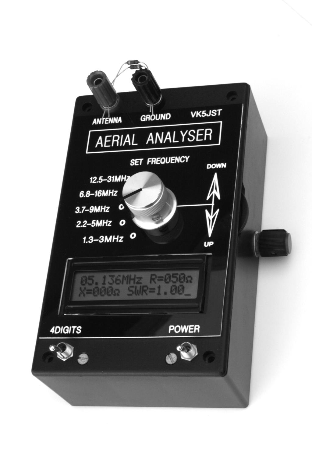
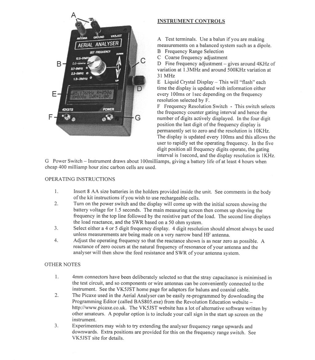
5 PLEASE NOTE THAT THESE INSTRUCTIONS ARE THE MINIMUM NEEDED TO COMPLETE THE KIT. MUCH GREATER DETAIL (AND OTHER GOODIES) INCLUDING COMPREHENSIVE DIAGNOSTIC DATA AND ADDITIONAL SOFTWARE ARE TO BE FOUND ON THE WEB SITE OF VK5JST ( IMPORTANT The Picaxe chip and LCD display are static sensitive devices. Avoid damage by using correct handling procedures. Essentially this means bringing everything to earth potential so that no discharges can occur. This means you, the chip being unpacked or handled, the solder, soldering iron and mainboard. THE THEORY Before starting construction, it is worth briefly considering the principles of operation so that construction can proceed logically. Heart of the unit is the test circuit shown above (please also see main circuit). To enable measurement of the full characteristics of the load, a 50 ohm resistor is placed between it and the variable frequency RF generator feeding the test circuit. Three AC voltages are then measured, by rectifying them to form DC. The peak value of each ac voltage is stored in a capacitor and the resulting dc passed on to the Picaxe processor. The three voltages are the generator output voltage (v GEN ), the voltage across the 50 ohm series resistance (v SERIES ) which represents the load current, and the voltage across the load (v LOAD ). From these three outputs, the SWR, the series load resistance, and the magnitude (but not sign) of the series load reactance can be calculated, and the mathematics for this is detailed in the original article to be found on the home page shown above. This leaves the question of how to determine whether the load reactance is capacitive or inductive. To answer this, the user simply changes the generator frequency slightly. If the magnitude of the series reactance increases as the frequency is increased then it is an inductor. And vice versa for a capacitor. Note that if the load resistance is a pure 50 ohm resistor, then exactly half of the ac generator voltage applied to the test circuit will appear across the 50 ohm load, and half across the 50 ohm resistor in the test circuit. This comment also applies to the dc voltages derived from these ac voltages, and this handy fact is used to calibrate the instrument to read 50 ohms and an SWR = 1 when it is being set up. HOW IT WORKS The process starts with an RF signal generator. This must provide a stable, flat, high level sinusoidal output into the test circuit, combined with a low output impedance. The need for frequency stability is obvious, while the low output impedance and flat output characteristic guarantee the largest possible signal into the microprocessor analog to digital converter inputs from the test circuit detectors. This ensures that independent of the load applied to the test circuit, the calculations will have maximum accuracy. The sinusoidal output ensures that the measurement occurs only at a single frequency and is not upset by what happens at harmonics of the generator frequency. These goals are attained by using an RF oscillator with an AGC circuit. Q3 and Q4 provide broadband gain (coupled collector to base then emitter to emitter), and the frequency of oscillation is set by the variable 160pf
6 tuning capacitor and inductors L1 L5. Fine tuning is provided by back to back varicap diodes fabricated from the reversed biased collector base junctions of Q1 and Q2. The level of oscillation is set by the current flowing through Q3 and Q4, which in turn is set by the AGC circuitry Q5 and Q6. At switch-on when there is no oscillation, the 2K7 resistor in the collector of Q6 turns Q5 hard on causing maximum current through Q3 and Q4, and hence rapid build up of oscillation. As the oscillation increases, Q6 acts as an envelope detector and its collector potential falls, starving Q5 of base potential and hence limiting the current through Q3 and Q4. This process stabilizes the level of oscillation. AGC action is excellent because the AGC system has a very high gain, and the result is a very constant level of oscillation at the emitter of Q7 of around 600mV p-p. This output is then buffered and amplified by a wideband power amplifier, comprised of Q8 through Q12. The amplifier provides a voltage gain of 5, and an output impedance of a few ohms to drive the test circuit with around 3 V p-p. The emitter follower Q8 provides a low impedance drive to a cascode voltage amplifier Q9 and Q10 (the cascode structure eliminates Miller effect and ensures a very wide bandwidth). These transistors in turn drive an emitter follower Q12 with active pull down Q11, ensuring equal current source and sink capabilities. The 70MHz bandwidth ensures the RF drive level to the test circuit remains flat to 30MHz. Drive for the frequency counting function of the microprocessor is stolen from the emitter of Q10, and is amplified and buffered using a 74LS04. This is then divided by 1024 in the following 74LS93 and 4040 divider chips, and the resulting frequency is measured with the Picaxe to form a frequency display. Dual gating intervals are provided for frequency counting function of around 0.1 second and 1 second under the control of a logic level on pin 13 of the microprocessor. The shorter gating interval allows the user to track and easily set the generator frequency, while the longer gating interval allows the accurate frequency measurements which are necessary on very odd occasions. In practice, the 1 second gate which gives 5 digit frequency accuracy will almost never be used, as this accuracy is only really necessary for very narrow band HF antennas such as multi element wire yagis. Also note that in line with standard frequency counter practice, the display will blink as is updated with new information at the end of each gating interval. To save precious microprocessor memory, only one display routine is used, and in the four digit mode, the last digit of the 5 digit frequency display is permanently set to zero. The 3 voltages discussed previously in the Theory section are derived from the test circuit using germanium diode envelope detectors. Note that only point contact germanium diodes can be used here (D4 D9) as despite what the schools usually teach, germanium diodes have a zero turn on potential provided the load resistance they drive is high enough (in this circuit around 50 Megohms). This is not the case with silicon diodes (with turn on potentials around 500mV) or even with the best zero bias hot carrier diodes, which actually have turn on potentials of around 100mV. For SWRs of around 10 (a 5 ohm load on the test circuit) only about 150mV peak will be applied to D6. For accurate calculation, it is very important to have linear detection. Even with germanium diodes, the bottom end of the detector characteristic is very non-linear and must be linearised somehow. This is achieved by using the diode characteristic against itself in negative feedback loops around IC1A, B, and C. Each linearised output is then amplified by 4.3 (IC2A, B, and C) before being applied to the A/D converter inputs of the microprocessor. Much software muscle is then used to produce displays of resistance, reactance and SWR. BUILDING THE ANALYSER The first item to complete is the instrument case. The blank PCB can be used as a template to accurately mark and drill the box lid for all terminals, mounting pillars and switches. Once this is done, the central hole for the frequency selecting switch in the lid can be used to position the engraved front panel, which in turn is used to mark out the hole for the liquid crystal display. This hole is carefully formed, and the front panel is then attached to the box lid with contact adhesive, or double sided adhesive tape. Next, using the component overlay provided, mount all components on the PCB starting with the lowest profile items and working upwards. The four links next to the two LM324 op amps go in first, followed by the six feed through connections, which connect various pads on the track side to the ground plane. It is firmly suggested that component leads are not bent over significantly on the track side of the board during soldering, as in the event of a mistake, this can make component removal very difficult and possibly cause permanent damage to the pcb. Use IC sockets. This allows progressive testing of the circuitry rather than the apply power to everything and hope approach.
7 Assume nothing!! Use your digital voltmeter to check the value of every resistor before installation. Check the pinouts of your transistors by using the current gain checking feature on your DVM. An indicated current gain of more than 50 shows you have the correct pinout. The printed circuit layout used is rather unusual in that a lot of component leads are soldered directly to the ground plane. This is deliberate as it is good rf practice, keeps the pcb cheap due to the lack of plated through holes, and allows the board to be made at home if desired. Keep the leads on all monolithic bypass capacitors to the absolute minimum possible length. Minimising stray capacitance in the test circuit is important, as it appears in parallel with the load and can very slightly upset measurements at high frequencies and high SWRs. It can be minimised by mounting the following components away from the ground plane by 1-2mm (a) D5 and the associated 100pf and 47K (b) D6 and the associated 100pf and 47K and (c) the two 100 ohm test circuit series resistors. Before mounting the band switch, remove the nut and lock washer and move the washer with the end stop pin so that the pin goes into hole position 5. This limits the switch rotation to five positions. Then place the switch into the printed circuit board so that pin 1 is near to the tuning capacitor body. This should be possible, using one of the four holes provided in the pcb for the locating pin on the switch body. Unfortunately, there are many variants of this single pole 12 position rotary switch design and at any one time it may not be possible to obtain exactly the same unit from our suppliers. Please see the comments on the VK5JST website if you have difficulties with the switch. It is NOT necessary to take the switch apart despite comments to the contrary on the web. In fact doing this is inviting disaster. Double-check all your soldering and component orientation/values very carefully, particularly those which will appear under the LCD when mounted. Finally, mount the LCD, spacing it away from the main PCB by 5-6 mm with a thin piece of polystyrene foam or similar. Use thin flexible tinned copper wire (0.5 mm dia) to interconnect these two boards - this will allow the LCD to be hinged away from the main board if there is an error or omission. Position the display correctly first, by just inserting the two outside connecting wires between the display and main board, and then soldering these to lock the display into final position. Then drop the central wires through the display and main board holes, soldering and trimming each wire in turn. The main board is then mounted on the front panel. It is supported at one end using countersunk screws and 10mm long nylon spacers, while the other end is supported by the two test terminals. The bottom of the case will need to be relieved so that the knob on the main tuning capacitor can protrude from the side of the case. Likewise the case bottom must be drilled to accommodate the miniature fine-tuning potentiometer, which mounts next to the batteries in the case bottom. Complete all wiring to the two switches, the battery holders, and the fine frequency adjusting potentiometer. Attach the battery holders to the case bottom with contact adhesive or double sided tape. Note that the unit requires a supply of 12 VDC. This means zinc carbon batteries must be used in the battery holders supplied. If you wish to NiCd or NiMH rechargeable cells (1.2 VDC) then 10 cells must be provided and the case bottom needs to be fitted with a 10 cell holder (not supplied) which will just fit the case if the reinforcing ribs at either end of the case are carefully removed (use a sharp wood chisel). Note that the much higher capacities of modern batteries also allows the use of rechargeable AAA cells. This completes all work on the case. SET UP AND TESTING With all ICs unplugged, apply 12 volt to the PCB. Check the output of the 5 Volt regulator with a multimeter ( VDC). The contrast pot should be adjusted so that the top line of the LCD displays all black squares. If you have an oscilloscope (50MHz or more preferred), fit it with a correctly set up X10 probe and monitor the emitter of Q7. Note that an X1 probe, which is really around 1 meter of coaxial cable with convenient connectors on each end, will totally wreck instrument operation due to excessive capacitive loading. A clean sine wave at a level of 600mV p-p +/- 10% should be present at Q7 emitter, independent of the frequency selected. Likewise, 3 volts peak to peak of rf at the hot rf test circuit terminal, or the junction of Q12 emitter/ Q11 collector, shows the oscillator and buffer amplifier are working properly. Fit the 2@LM324s. If you don t have a scope, correct operation of the oscillator and buffer amplifier will be indicated by around 1.4VDC appearing at IC1 pin 14 at all frequencies (the peak value of the rectified ac at the input to the test circuit). With the TRIM FREQUENCY pot set centrally, the main tuning capacitor set to minimum capacitance, and the 12.5 to 30MHz range selected, monitor the hot test circuit terminal with a frequency counter and use the
8 trimmer on the main tuning capacitor to set the output frequency to 31MHz. Now check the frequency coverage on all ranges. Finally, set the oscillator frequency to 2MHz. Switch off. Plug in the 74LSO4, 74LS93, and Switch on. Your scope should show around 2KHz of 5V p-p square wave at pin 14 of the PICAXE if the pre-scaler is working correctly. Check prescaler operation (divide by 1024) on all other frequency ranges and then re-set the frequency to around 2MHz. Without a scope you will have to wait until the Picaxe is plugged in to check prescaler operation. This will be shown by the LCD indicating the correct frequency. Connect two 100 ohm 1% 1/4watt metal film resistors across the test terminals (50 ohms). Monitor TP2 with a DVM and adjust P1 until a DC voltage of exactly volts appears. Then adjust P2 and P3 until exactly volts appears at TP3 and TP4 when checked with the DVM. This completes initial calibration. Switch off and plug in the Picaxe. Switch on. Your analyser should now be alive! For the first 1.5 seconds the battery voltage should be indicated with an accuracy of around +/- 5%, and then the display should show a frequency of around 2MHz, R=050ohms, X=000ohms, and SWR=1.00. Recheck the voltages at TP2, 3 and 4 if this is not the case, and also measure the battery drain (around 100mA total). Also check that the fast and slow frequency gating intervals are correct (4 or 5 digit mode). If the frequency indicated is around 8MHz and the gating is very slow, the Picaxe is using its internal RC default clock of 4MHz instead of the external 16MHz crystal, and you have a fault in the crystal circuit connected to pins 9 and 10 of the Picaxe. This is also possible if you have decided not to use the preprogrammed Picaxe supplied, but instead have loaded the Picaxe yourself with an early version of the software written for the Picaxe 28X rather than the Picaxe 28X1 supplied with the kit. See the VK5JST homepage for a fix. Remove the ohm load resistors and replace them with a single 270 ohm 0.25 watt metal film resistor with short leads. The analyzer should now indicate a resistance of 270 ohms+/- 10% together with an SWR of around 5.4 and a reactance of zero. If the reactance X is not zero, adjust P3 by a small amount until it is. Recheck the analyzer with the 50 ohm load again. This double check forces best linearity over the impedance range. Depending on the circuit conditions for which your crystal was made, you may wish to slightly change the count periods specified in the count statements in the software so that the analyser shows an exactly correct frequency. You can also modify the battery voltage indicated at switch on, and this can be adjusted in two ways. The value of one of the resistors which form the voltage divider connected to Picaxe pin 5 (16K and 3K9) can be adjusted, or you can modify a constant provided in the battery measuring routine within the Picaxe software. If you wish to modify the analyser software, please see the procedure detailed on the VK5JST homepage. Connect a 300mm length of hook up wire between the test terminals and select a frequency of around 30MHz. Depending on the wire diameter and the shape of the single turn coil you have made, the skin effect resistance will be around 4-10 ohms and the inductive reactance around 80 ohms. When the wire is disconnected the instrument will display the reactance and loss resistance of the few pf of stray capacitance in the test circuit and will not indicate an open circuit until the frequency falls below about 15MHz. Another way of looking at this is to say that the instrument is displaying the characteristics of a very short length of transmission line connected to the test circuit (the terminals etc). There are typically around 4 pf of strays in the test circuit and standard coaxial cable has a capacitance of 100 pf/metre and so the strays equate to an unterminated length of coax of around 40mm. In any practical HF measurement, this will be absorbed into the antenna and feed line being measured and is so short it is negligible. Congratulations, and enjoy using your analyser. AHARS November 2011
9
10
MFJ-249B HF/VHF SWR ANALYZER
 TABLE OF CONTENTS MFJ-249B... 2 Introduction... 2 Powering The MFJ-249B... 3 Battery Installation... 3 Alkaline Batteries... 3 NiCd Batteries... 4 Power Saving Mode... 4 Operation Of The MFJ-249B...5 SWR
Assembly Instructions for the 1.5 Watt Amplifier Kit
 Assembly Instructions for the 1.5 Watt Amplifier Kit 1.) All of the small parts are attached to a sheet of paper indicating both their value and id. 2.) Leave the parts affixed to the paper until you are
Assembly Instructions for the FRB FET FM 70 Watt Amp
 Assembly Instructions for the FRB FET FM 70 Watt Amp 1.) Orient the circuit board with the diagram 2.) Use a narrow chisel tip 25-30 watt soldering iron for assembly 3.) All the small parts are taped onto
LA502 Assembly guide Main PCB Resistors - (2)
") LA502 Assembly guide Safety warning The kits are main powered and use potentially lethal voltages. Under no circumstance should someone undertake the realisation of a kit unless he has full knowledge about
LA502 Assembly guide Safety warning The kits are main powered and use potentially lethal voltages. Under no circumstance should someone undertake the realisation of a kit unless he has full knowledge about
G6ALU 20W FET PA Construction Information
 G6ALU 20W FET PA Construction Information The requirement This amplifier was designed specifically to complement the Pic-A-Star transceiver developed by Peter Rhodes G3XJP. From the band pass filter an
Stand Alone VXO (SAVXO) Assembly Manual Manual Version 1.0B_
 Assembly Manual Manual Version 1.0B_") Stand Alone VXO (SAVXO) Assembly Manual Manual Version.0B_0-6-0 Designed by: Jim Kortge, K8IQY Kitted & Sold by: 4 State QRP Group Copyright: 0 Forward Thank you for purchasing a 4 State QRP Group Stand
Stand Alone VXO (SAVXO) Assembly Manual Manual Version.0B_0-6-0 Designed by: Jim Kortge, K8IQY Kitted & Sold by: 4 State QRP Group Copyright: 0 Forward Thank you for purchasing a 4 State QRP Group Stand
PA FAN PLATE ASSEMBLY 188D6127G1 SYMBOL PART NO. DESCRIPTION. 4 SBS /10 Spring nut. 5 19A702339P510 Screw, thread forming, flat head.
 MAINTENANCE MANUAL 851-870 MHz, 110 WATT POWER AMPLIFIER 19D902797G5 TABLE OF CONTENTS Page DESCRIPTION.............................................. Front Page SPECIFICATIONS.................................................
HT-1A Dual Band CW QRP Transceiver. Kit Building Instructions
 HT-A Dual Band CW QRP Transceiver Kit Building Instructions Rev B, July 8, 08 Designed by BD4RG Exclusively distributed by CRKITS.COM and its worldwide distributors Join the group http://groups.io/g/crkits
REPAIRING THE RM KL400 LINEAR AMPLIFIER.
 REPAIRING THE RM KL400 LINEAR AMPLIFIER. Les Carpenter G4CNH December 2012 Page 1 of 20 The following is a step by step guide to fixing your KL400 amplifier. Each part will be individually tested up to
TS500 Assembly guide. Soldering. TS500 Assembly guide Main PCB 1. Diodes. Document revision 1.2 Last modification : 17/12/16
 TS500 Assembly guide Safety warning The kits are main powered and use potentially lethal voltages. Under no circumstance should someone undertake the realisation of a kit unless he has full knowledge about
Technical Bulletin A Versatile Pulse Tester Page 1 of 6
 Technical Bulletin A Versatile Pulse Tester Page 1 of 6 A Versatile Pulse Tester By G8MNY (BATC's CQTV No 195, Updated Oct 07) (8 Bit ASCII Graphics use code page 437 or 850) This tester based on ideas
MFJ-203 Bandswitched Dip Meter
 MFJ-203 Bandswitched Dip Meter Thank you for purchasing the MFJ-203 Bandswitched Dip Meter. The MFJ-203 Bandswitched Dip Meter is a solid state bandswitched adaptation of the traditional grid dip meter.
Experiment 1: Instrument Familiarization (8/28/06)
") Electrical Measurement Issues Experiment 1: Instrument Familiarization (8/28/06) Electrical measurements are only as meaningful as the quality of the measurement techniques and the instrumentation applied
Electrical Measurement Issues Experiment 1: Instrument Familiarization (8/28/06) Electrical measurements are only as meaningful as the quality of the measurement techniques and the instrumentation applied
Building a Bitx20 Version 3
 Building a Bitx20 Version 3 The board can be broken into sections and then built and tested one section at a time. This will make troubleshooting easier as any problems will be confined to one small section.
The 144MHz Anglian 3 transverter
 The 144MHz Anglian 3 transverter A high performance 144/28MHz transverter G4DDK document issue 1 12/9/16 Introduction Anglian 3 is an update to the 144MHz Anglian 2 transverter. The Anglian 2 is no longer
Experiment 1: Instrument Familiarization
 Electrical Measurement Issues Experiment 1: Instrument Familiarization Electrical measurements are only as meaningful as the quality of the measurement techniques and the instrumentation applied to the
THE 1956 ZENITH ROYAL 500 TRANSISTOR OWL S EYES RADIO.
 THE 1956 ZENITH ROYAL 500 TRANSISTOR OWL S EYES RADIO. Dr. H. Holden. Feb. 2018. Introduction: The Zenith Royal 500 radio appeared in 1956, two years later than the Regency TR1 which was the first commercial
ericssonz LBI-38640E MAINTENANCE MANUAL FOR VHF TRANSMITTER SYNTHESIZER MODULE 19D902780G1 DESCRIPTION
 MAINTENANCE MANUAL FOR VHF TRANSMITTER SYNTHESIZER MODULE 19D902780G1 TABLE OF CONTENTS Page DESCRIPTION........................................... Front Cover GENERAL SPECIFICATIONS...................................
SPECIFICATIONS: Subcarrier Frequency 5.5MHz adjustable, FM Modulated +/- 50KHz. 2nd 11MHz >40dB down from 5.5MHz
 Mini-kits AUDIO / SUBCARRIER KIT EME75 Version4 SPECIFICATIONS: Subcarrier Frequency 5.5MHz adjustable, FM Modulated +/- 50KHz Subcarrier Output 1.5v p-p Output @ 5.5MHz DESCRIPTION & FEATURES: The Notes
HAMTRONICS TB901 FM EXCITER INSTALLATION, OPERATION, & MAINTENANCE
 HAMTRONICS TB901 FM EXCITER INSTALLATION, OPERATION, & MAINTENANCE GENERAL INFORMATION. The TB901 is a single-channel low power fm transmitter (exciter) designed to provide 300-600 milliwatts continuous
Construction Manual 6m-Linear-Transverter XV6/10
 Construction Manual 6m-Linear-Transverter XV6/10 Holger Eckardt DF2FQ Kirchstockacherstr. 33 D-85662 Hohenbrunn 2606 Technical data exciter frequency: 28... 30 MHz RF frequency: 50... 52 MHz supply voltage:
WA3RNC 30 METER CRYSTALPLEXER TRANSMITTER KIT ASSEMBLY INSTRUCTIONS
 WA3RNC 30 METER CRYSTALPLEXER TRANSMITTER KIT ASSEMBLY INSTRUCTIONS Description The WA3RNC 30 Meter Crystalplexer is a low power crystal controlled QRP transmitter offering a significantly improved tuning
Hendricks QRP Kits BITX20A to BITX17A Conversion Instructions
 Hendricks QRP Kits BITX20A to BITX17A Conversion Instructions 30 November 2008 Converting your BITX20A Kit to a BITX17A Kit is not all that complex. It only requires that you change crystals and some resonance
QUASAR PROJECT KIT # /24 HOUR GIANT CLOCK
 This project was originally published in the electronics magazine, Silicon Chip, a few years ago. It is issued here as a kit with permission. Some modifications to the original published circuit and software
Chapter 6. FM Circuits
 Chapter 6 FM Circuits Topics Covered 6-1: Frequency Modulators 6-2: Frequency Demodulators Objectives You should be able to: Explain the operation of an FM modulators and demodulators. Compare and contrast;
Custom Integrated Circuit (MSM9520RS) Replacement Module
 Replacement Module") FT-101Z/ FT-107/ FT-707/ FT-901,902 (later version) DISPLAY COUNTER UNIT (PB-2086A) Custom Integrated Circuit (MSM9520RS) Replacement Module Assembly and Installation Manual (v1.3e) STEP-BY-STEP PROCEDURES
FT-101Z/ FT-107/ FT-707/ FT-901,902 (later version) DISPLAY COUNTER UNIT (PB-2086A) Custom Integrated Circuit (MSM9520RS) Replacement Module Assembly and Installation Manual (v1.3e) STEP-BY-STEP PROCEDURES
Easy Transmitter. Support ETX_REV5_Manual V2.7 Revised
 Easy Transmitter Introduction The Easy Transmitter kit from qrpkits.com provides a basic, crystal controlled transmitter with VXO tuning to provide a small tuning range around the crystal frequency. It
MAINTENANCE MANUAL RF BOARD 19D901835G1 ( MHz) 19D901835G2 ( MHz) FOR MVS
 19D901835G2 ( MHz) FOR MVS") D MAINTENANCE MANUAL F BOAD 19D901835G1 (136-153 MHz) 19D901835G2 (150-174 MHz) FO MVS TABLE OF CONTENTS DESCIPTION............................................... Front Cover CICUIT ANALYSIS..............................................
D MAINTENANCE MANUAL F BOAD 19D901835G1 (136-153 MHz) 19D901835G2 (150-174 MHz) FO MVS TABLE OF CONTENTS DESCIPTION............................................... Front Cover CICUIT ANALYSIS..............................................
HF Amateur SSB Receiver
 HF Amateur SSB Receiver PCB Set for radio club project http://rhelectronics.net PCB for DIY HF Amateur SSB Receiver 20M The receiver is a simple syperheterodyne type with quartz crystal filter. The circuit
DIY Function Generator XR2206
 DIY Function Generator XR2206 20Hz 100KHz http://radiohobbystore.com Components List: Resistors: R1, R2 1% Metal Film 5K1 R4 1% Metal Film 10K R5 1% Metal Film 3K R10 5% Carbon Film 10R R3, R9 Potentiometer
LBI-30398N. MAINTENANCE MANUAL MHz PHASE LOCK LOOP EXCITER 19D423249G1 & G2 DESCRIPTION TABLE OF CONTENTS. Page. DESCRIPTION...
 MAINTENANCE MANUAL 138-174 MHz PHASE LOCK LOOP EXCITER 19D423249G1 & G2 LBI-30398N TABLE OF CONTENTS DESCRIPTION...Front Cover CIRCUIT ANALYSIS... 1 MODIFICATION INSTRUCTIONS... 4 PARTS LIST AND PRODUCTION
KN-Q10 Assembly Manual
 KN-Q10 Assembly Manual Translated by Adam Rong, BD6CR/4 with permission from Ke Shi, BA6BF Edited by Stephen, VK2RH Revision B, Oct 14, 2010 Thank you for purchasing the KN-Q10 4 Band SSB/CW Dual Mode
Construction notes for the symmetrical 400 watt amplifier
 Construction notes for the symmetrical 400 watt amplifier Introduction The symmetrical amplifier is an update of one of my designs, which appeared in the Australian electronics magazine Silicon Chip in
The Walford Electronics Ford Receiver Kit Project Construction Manual
 The Walford Electronics Ford Receiver Kit Project Construction Manual Walford Electronics Ford Receiver construction manual V1.5 Page 1 of 22 Introduction The Ford receiver has four stages: The first stage
Construction Manual 4m-Linear-Transverter XV4-15
 Construction Manual 4m-Linear-Transverter XV4-15 Holger Eckardt DF2FQ Kirchstockacherstr. 33 D-85662 Hohenbrunn 3207 Technical data exciter frequency: 21.0... 21.5 MHz RF frequency: 70.0.. 70.5 MHz supply
LED S METER CONSTRUCTION MANUAL. LED S meter Construction Manual Issue 1.0 Page 1
 LED S METER CONSTRUCTION MANUAL LED S meter Construction Manual Issue 1.0 Page 1 Important Please read before starting assembly STATIC PRECAUTION The LED S Meter kit contains components which can be damaged
ERICSSONZ LBI-30398P. MAINTENANCE MANUAL MHz PHASE LOCKED LOOP EXCITER 19D423249G1 & G2 DESCRIPTION TABLE OF CONTENTS
 MAINTENANCE MANUAL 138-174 MHz PHASE LOCKED LOOP EXCITER 19D423249G1 & G2 TABLE OF CONTENTS Page DESCRIPTION... Front Cover CIRCUIT ANALYSIS...1 MODIFICATION INSTRUCTIONS...4 PARTS LIST...5 PRODUCTION
Step by Step Building PJ meter ARDF Receiver Kit. CRKITS.COM August 5, 2013
 Step by Step Building PJ-80 80-meter ARDF Receiver Kit CRKITS.COM August 5, 2013 What is ARDF? ARDF is the abbreviation of Amateur Radio Direction Finding, or so called Fox Hunting. If you are looking
GATE: Electronics MCQs (Practice Test 1 of 13)
") GATE: Electronics MCQs (Practice Test 1 of 13) 1. Removing bypass capacitor across the emitter leg resistor in a CE amplifier causes a. increase in current gain b. decrease in current gain c. increase
GATE: Electronics MCQs (Practice Test 1 of 13) 1. Removing bypass capacitor across the emitter leg resistor in a CE amplifier causes a. increase in current gain b. decrease in current gain c. increase
FMR622S DUAL NARROW BAND SLIDING DE-EMPHASIS DEMODULATOR INSTRUCTION BOOK IB
 FMR622S DUAL NARROW BAND SLIDING DE-EMPHASIS DEMODULATOR INSTRUCTION BOOK IB 1222-22 TABLE OF CONTENTS SECTION 1.0 INTRODUCTION 2.0 INSTALLATION & OPERATING INSTRUCTIONS 3.0 SPECIFICATIONS 4.0 FUNCTIONAL
OBJECTIVE TYPE QUESTIONS
 OBJECTIVE TYPE QUESTIONS Q.1 The breakdown mechanism in a lightly doped p-n junction under reverse biased condition is called (A) avalanche breakdown. (B) zener breakdown. (C) breakdown by tunnelling.
Glossary + - A BNC plug that shorts the inner wire in a coax cable to the outer shield through a
 50Ω Terminator AC Active Alligator Clip Back Bias Base Battery Bias + - Bipolar Transistor BJT Black Box BNC BNC Cable A BNC plug that shorts the inner wire in a coax cable to the outer shield through
onlinecomponents.com FET Circuit Applications FET Circuit Applications AN-32 National Semiconductor Application Note 32 February 1970
 FET Circuit Applications National Semiconductor Application Note 32 February 1970 Polycarbonate dielectric Sample and Hold With Offset Adjustment TL H 6791 1 Long Time Comparator TL H 6791 2 The 2N4393
Ameritron ALS-600 Retrofit ALS-600-LPF Assembly Manual
 Ameritron ALS-600 Retrofit ALS-600-LPF Assembly Manual FEATURES Automatic band change based on TX frequency. PIN diode QSK RX/TX switch. Temperature controlled FAN for quiet operation. RS-232 serial port
MFJ-219/219N 440 MHz UHF SWR Analyzer TABLE OF CONTENTS
 MFJ-219/219N 440 MHz UHF SWR Analyzer TABLE OF CONTENTS Introduction...2 Powering The MFJ-219/219N...3 Battery Installation...3 Operation Of The MFJ-219/219N...4 SWR and the MFJ-219/219N...4 Measuring
1 TRANSISTOR CIRCUITS
 FM TRANSMITTERS The first group of circuits we will discuss are FM TRANSMITTERS. They can be called SPY TRANSMITTERS, FM BUGS, or a number of other interesting names. They all do the same thing. They transmit
Capacitive Touch Sensing Tone Generator. Corey Cleveland and Eric Ponce
 Capacitive Touch Sensing Tone Generator Corey Cleveland and Eric Ponce Table of Contents Introduction Capacitive Sensing Overview Reference Oscillator Capacitive Grid Phase Detector Signal Transformer
ASSEMBLY MANUAL FOR R3500D DIRECTION FINDING RECEIVER KIT
 SDR-Kits www.sdr-kits.net SDR-Kits is CRKITS Authorised Distributor for Europe ASSEMBLY MANUAL FOR R3500D DIRECTION FINDING RECEIVER KIT Rev. A May 24, 2015 Written by CRKITS http://www.crkits.com Thanks
Read This Page First
 Read This Page First If you are reading this you know the manuals are always available at QRPKITS.com. This is version 8.0 of the manual dated 4/27/2016. There is no need to print out the whole assembly
SoftRock v5.0 Builder s Notes. December 12, Building a QSD Kit
 SoftRock v5.0 Builder s Notes December 12, 2005 Building a QSD Kit Be sure to use a grounded tip soldering iron in building the QSD board. The soldering iron needs to have a small tip, (0.05-0.1 inch diameter),
MFJ 259 Operation & Simplified Calibration
 MFJ 259 Operation & Simplified Calibration Bill Leonard N0CU NA0TC 2014 TechFest 1 What Will Be Covered Part 1: Operation What is an MFJ 259 What Does It Measure Impedance & Admittance How Does It Work
RBS RADIO BATTERY SWITCH CONSTRUCTION MANUAL. RBS Construction Manual Issue 1 Page 1
 RBS RADIO BATTERY SWITCH CONSTRUCTION MANUAL RBS Construction Manual Issue 1 Page 1 CONTENTS 1 Introduction... 4 1.1 RBS features... 4 2 Batteries... 5 3 RBS specifications... 6 4 Circuit Description...
IR add-on module circuit board assembly - Jeffrey La Favre January 27, 2015
 IR add-on module circuit board assembly - Jeffrey La Favre January 27, 2015 1 2 For the main circuits of the line following robot you soldered electronic components on a printed circuit board (PCB). The
DIGITAL / ANALOG TRAINER
 DIGITAL / ANALOG TRAINER MODEL XK-150 A COMPLETE MINI-LAB FOR BUILDING, TESTING AND PROTOTYPING ANALOG AND DIGITAL CIRCUITS Instruction Manual ELENCO Copyright 2016, 1998 by ELENCO Electronics, Inc. All
THE INTERMEDIATE VFO
 THE INTERMEDIATE VFO Some Intermediate tutors have reported difficulties in either obtaining parts for the RSGB Intermediate textbook VFO or in getting the VFO going once they have the parts. This alternative
1 FUNCTIONAL DESCRIPTION WAY SPLITTER/INPUT BOARD FET RF AMPLIFIERS WAY POWER COMBINER VSWR CONTROL BOARD...
 CONTENTS 1 FUNCTIONAL DESCRIPTION...1 2 4-WAY SPLITTER/INPUT BOARD...2 3 FET RF AMPLIFIERS...3 4 4-WAY POWER COMBINER...4 5 VSWR CONTROL BOARD...5 6 ADJUSTMENT OF BIAS VOLTAGE TO ESTABLISH PROPER QUIESCENT
SoftRock v6.0 Builder s Notes. May 22, 2006
 SoftRock v6.0 Builder s Notes May 22, 2006 Be sure to use a grounded tip soldering iron in building the v6.0 SoftRock circuit board. The soldering iron needs to have a small tip, (0.05-0.1 inch diameter),
FM RADIO KIT ESSENTIAL INFORMATION. Version 2.0 GET IN TUNE WITH THIS
 ESSENTIAL INFORMATION BUILD INSTRUCTIONS CHECKING YOUR PCB & FAULT-FINDING MECHANICAL DETAILS HOW THE KIT WORKS GET IN TUNE WITH THIS FM RADIO KIT Version 2.0 Build Instructions Before you start, take
For the filter shown (suitable for bandpass audio use) with bandwidth B and center frequency f, and gain A:
 with bandwidth B and center frequency f, and gain A:") Basic Op Amps The operational amplifier (Op Amp) is useful for a wide variety of applications. In the previous part of this article basic theory and a few elementary circuits were discussed. In order to
Basic Op Amps The operational amplifier (Op Amp) is useful for a wide variety of applications. In the previous part of this article basic theory and a few elementary circuits were discussed. In order to
GLOSSARY. A connector used to T together two BNC coax cables and a BNC jack. The transfer function vs. frequency plotted on Log Log axis.
 GLOSSARY 50ΩTerminator AC Active Alligator Clip Back Bias Base Battery Bias + - Bipolar Transistor BJT Black Box BNC BNC Cable A BNC plug that shorts the inner wire in a coax cable to the outer shield
The Hartley Oscillator
 The Hartley Oscillator One of the main disadvantages of the basic LC Oscillator circuit we looked at in the previous tutorial is that they have no means of controlling the amplitude of the oscillations
RadiØKit Μ CW HAM RADIO TRANSCEIVER KIT. Assembly and operating manual
 RadiØKit-120 20Μ CW HAM RADIO TRANSCEIVER KIT Assembly and operating manual Boreiou Ipirou 78 Kolonos Athens- Greece - 10444 Tel: 210.5150527 210.5132673 www.freebytes.com Thank you for buying RadiØKit-1,
IPR LA-3 KIT last update 15 march 06
 IPR LA-3 KIT last update 15 march 06 PART-2: Audio Circuitry CIRCUIT BOARD LAYOUT: Power and Ground Distribution Now that your power supply is functional, it s time to think about how that power will be
EVALUATION KIT AVAILABLE 10MHz to 1050MHz Integrated RF Oscillator with Buffered Outputs. Typical Operating Circuit. 10nH 1000pF MAX2620 BIAS SUPPLY
 19-1248; Rev 1; 5/98 EVALUATION KIT AVAILABLE 10MHz to 1050MHz Integrated General Description The combines a low-noise oscillator with two output buffers in a low-cost, plastic surface-mount, ultra-small
Lab Hints. How to reduce the degree of effort in testing lab assignments GENERAL WIRING PARASITICS... 2 OSCILLATION... 3
 Lab Hints How to reduce the degree of effort in testing lab assignments GENERAL WIRING PARASITICS... 2 OSCILLATION... 3 COUPLING & OSCILLATION DUE TO SLOPPY WIRING ON THE BENCH... 3 SHARING OF GROUND CONNECTIONS
VECTRONICS. SWR-66 Dip Meter Adapter
 INTRODUCTION VECTRONICS SWR-66 Dip Meter Adapter Thank you for purchasing the SWR-66 Dip Meter Adapter. The SWR-66 Dip Meter Adapter works with your Vectronics SWR-584 HF/VHF SWR Analyzer. The SWR-66 Dip
Foxhunt Offset Attenuator. Parts List:
 When your closing in on the fox you may find the signals to be so strong that you can no longer find a peak or null with your antenna. Sometimes the signal is so strong that the RF will leak straight into
DEPARTMENT OF ELECTRICAL ENGINEERING AND COMPUTER SCIENCE MASSACHUSETTS INSTITUTE OF TECHNOLOGY CAMBRIDGE, MASSACHUSETTS 02139
 DEPARTMENT OF ELECTRICAL ENGINEERING AND COMPUTER SCIENCE MASSACHUSETTS INSTITUTE OF TECHNOLOGY CAMBRIDGE, MASSACHUSETTS 019.101 Introductory Analog Electronics Laboratory Laboratory No. READING ASSIGNMENT
Ten Tec DDS Board Assembly Procedure
 05 May 2014 Ten Tec DDS Board Assembly Procedure You will find a photo of a completed board at the end of these instructions. Refer it whenever clarification is required. 1. AD9835 Attachment If you purchased
LABORATORY #3 QUARTZ CRYSTAL OSCILLATOR DESIGN
 LABORATORY #3 QUARTZ CRYSTAL OSCILLATOR DESIGN OBJECTIVES 1. To design and DC bias the JFET transistor oscillator for a 9.545 MHz sinusoidal signal. 2. To simulate JFET transistor oscillator using MicroCap
ICOM IC-201 Allmode Transceiver
 ICOM IC-201 Allmode Transceiver Alignment Procedure Please note: This procedure is reengineered by myself and may be not in accordance with the original procedure from the manufacturer! So I can t accept
ENGINEERING TRIPOS PART II A ELECTRICAL AND INFORMATION ENGINEERING TEACHING LABORATORY EXPERIMENT 3B2-B DIGITAL INTEGRATED CIRCUITS
 ENGINEERING TRIPOS PART II A ELECTRICAL AND INFORMATION ENGINEERING TEACHING LABORATORY EXPERIMENT 3B2-B DIGITAL INTEGRATED CIRCUITS OBJECTIVES : 1. To interpret data sheets supplied by the manufacturers
GRID DIP METER DESIGN
 GRID DIP METER DESIGN BY G0CWA MAY 2013 This, my next offering of test equipment is an exceptionally useful item of test equipment with many uses, some are listed below. To coin a phrase given to me by
Op Amp Booster Designs
 Op Amp Booster Designs Although modern integrated circuit operational amplifiers ease linear circuit design, IC processing limits amplifier output power. Many applications, however, require substantially
1. What is the unit of electromotive force? (a) volt (b) ampere (c) watt (d) ohm. 2. The resonant frequency of a tuned (LRC) circuit is given by
 volt (b) ampere (c) watt (d) ohm. 2. The resonant frequency of a tuned (LRC) circuit is given by") Department of Examinations, Sri Lanka EXAMINATION FOR THE AMATEUR RADIO OPERATORS CERTIFICATE OF PROFICIENCY ISSUED BY THE DIRECTOR GENERAL OF TELECOMMUNICATIONS, SRI LANKA 2004 (NOVICE CLASS) Basic Electricity,
Department of Examinations, Sri Lanka EXAMINATION FOR THE AMATEUR RADIO OPERATORS CERTIFICATE OF PROFICIENCY ISSUED BY THE DIRECTOR GENERAL OF TELECOMMUNICATIONS, SRI LANKA 2004 (NOVICE CLASS) Basic Electricity,
Technician Licensing Class T6
 Technician Licensing Class T6 Amateur Radio Course Monroe EMS Building Monroe, Utah January 11/18, 2014 January 22, 2014 Testing Session Valid dates: July 1, 2010 June 30, 2014 Amateur Radio Technician
LM2462 Monolithic Triple 3 ns CRT Driver
 LM2462 Monolithic Triple 3 ns CRT Driver General Description The LM2462 is an integrated high voltage CRT driver circuit designed for use in color monitor applications. The IC contains three high input
A 75-Watt Transmitter for 3 Bands Simplified Shielding and Filtering for TVI BY DONALD H. MIX, W1TS ARRL Handbook 1953 and QST, October 1951
 A 75-Watt Transmitter for 3 Bands Simplified Shielding and Filtering for TVI BY DONALD H. MIX, W1TS ARRL Handbook 1953 and QST, October 1951 The transmitter shown in the photographs is a 3-stage 75-watt
PART MAX2605EUT-T MAX2606EUT-T MAX2607EUT-T MAX2608EUT-T MAX2609EUT-T TOP VIEW IND GND. Maxim Integrated Products 1
 19-1673; Rev 0a; 4/02 EVALUATION KIT MANUAL AVAILABLE 45MHz to 650MHz, Integrated IF General Description The are compact, high-performance intermediate-frequency (IF) voltage-controlled oscillators (VCOs)
Lab 4. Crystal Oscillator
 Lab 4. Crystal Oscillator Modeling the Piezo Electric Quartz Crystal Most oscillators employed for RF and microwave applications use a resonator to set the frequency of oscillation. It is desirable to
Pacific Antenna 20 and 40M Lightweight Dipole Kit
 Pacific Antenna 20 and 40M Lightweight Dipole Kit Antenna diagram showing configuration and lengths when assembled 7 8 16 9 16 9 Description The Pacific Antenna lightweight dual band dipole kit provides
Dual, Current Feedback Low Power Op Amp AD812
 a FEATURES Two Video Amplifiers in One -Lead SOIC Package Optimized for Driving Cables in Video Systems Excellent Video Specifications (R L = ): Gain Flatness. db to MHz.% Differential Gain Error. Differential
MFJ-834 RF Ammeter. Introduction. Uses
 MFJ-834 RF Ammeter Introduction Congratulations on purchasing the MFJ-834 RF Ammeter. The MFJ-834 is designed for measuring in-line RF feedline current on 1.8-30 MHz while having low interaction on the
Project Report Designing Wein-Bridge Oscillator
 Abu Dhabi University EEN 360 - Electronic Devices and Circuits II Project Report Designing Wein-Bridge Oscillator Author: Muhammad Obaidullah 03033 Bilal Arshad 0929 Supervisor: Dr. Riad Kanan Section
Home Map Projects Construction Soldering Study Components Symbols Membership FAQ Links
 Home Map Projects Construction Soldering Study Components Symbols Membership FAQ Links Multimeters Choosing Digital Analogue Voltage & Current Resistance Diode Transistor Next Page: Resistance Also See:
DDS VFO 2 CONSTRUCTION MANUAL. DDS VFO 2 Construction Manual Issue 1 Page 1
 DDS VFO 2 CONSTRUCTION MANUAL DDS VFO 2 Construction Manual Issue 1 Page 1 Important Please read before starting assembly STATIC PRECAUTION The DDS VFO kit contains the following components which can be
MP573 Assembly guide. Soldering. MP573 Assembly guide PCB split PCB split. Document revision 2.2 Last modification : 22/08/17
 MP573 Assembly guide Safety warning The kits are main powered and use potentially lethal voltages. Under no circumstance should someone undertake the realisation of a kit unless he has full knowledge about
THE AMAZING BARLOW WADLEY XCR-30 CRYSTAL CONTROLLED 30 BAND TRANSISTOR RADIO. (A method to set the AGC) H. Holden, 2018.
 H. Holden, 2018.") THE AMAZING BARLOW WADLEY XCR-30 CRYSTAL CONTROLLED 30 BAND TRANSISTOR RADIO. (A method to set the AGC) H. Holden, 2018. Introduction: The Barlow Wadley XCR-30 radio is well known to amateur radio enthusiasts
THE AMAZING BARLOW WADLEY XCR-30 CRYSTAL CONTROLLED 30 BAND TRANSISTOR RADIO. (A method to set the AGC) H. Holden, 2018. Introduction: The Barlow Wadley XCR-30 radio is well known to amateur radio enthusiasts
AC/DC ELECTRONICS LABORATORY
 Includes Teacher's Notes and Typical Experiment Results Instruction Manual and Experiment Guide for the PASCO scientific Model EM-8656 012-05892A 1/96 AC/DC ELECTRONICS LABORATORY 1995 PASCO scientific
Source: IC Layout Basics. Diodes
 Source: IC Layout Basics C HAPTER 7 Diodes Chapter Preview Here s what you re going to see in this chapter: A diode is a PN junction How several types of diodes are built A look at some different uses
Wiring Manual NEScaf April 2010 (August 2006)
") Wiring Manual NEScaf April 2010 (August 2006) Switched Capacitor Audio Filter The NEScaf is a switched capacitor audio filter (acronym SCAF) built around a building-block type filter chip. The NEScaf will
Wiring Manual NEScaf April 2010 (August 2006) Switched Capacitor Audio Filter The NEScaf is a switched capacitor audio filter (acronym SCAF) built around a building-block type filter chip. The NEScaf will
Wimborne Publishing, reproduce for personal use only
 In part 1 we looked at some of the principles involved with measuring magnetic fields. This time, we take a more practical approach and look at some experimental circuits. The circuits illustrated are
Pre-Laboratory Assignment
 Measurement of Electrical Resistance and Ohm's Law PreLaboratory Assignment Read carefully the entire description of the laboratory and answer the following questions based upon the material contained
EE 368 Electronics Lab. Experiment 10 Operational Amplifier Applications (2)
") EE 368 Electronics Lab Experiment 10 Operational Amplifier Applications (2) 1 Experiment 10 Operational Amplifier Applications (2) Objectives To gain experience with Operational Amplifier (Op-Amp). To
EE 368 Electronics Lab Experiment 10 Operational Amplifier Applications (2) 1 Experiment 10 Operational Amplifier Applications (2) Objectives To gain experience with Operational Amplifier (Op-Amp). To
Assembly Instructions
 Assembly Instructions For the SSQ-2F 3.1 MHz Rife Controller Board Kit v1.41 Manual v1.00 2012 by Ralph Hartwell Spectrotek Services GENERAL ASSEMBLY INSTRUCTIONS Arrange for a clean work surface with
T6A4. Electrical components; fixed and variable resistors, capacitors, and inductors; fuses, switches, batteries
 Amateur Radio Technician Class Element Course Presentation ti ELEMENT SUB-ELEMENTS Technician Licensing Class Supplement T Electrical/Electronic Components Exam Questions, Groups T - FCC Rules, descriptions
VCO Design Project ECE218B Winter 2011
 VCO Design Project ECE218B Winter 2011 Report due 2/18/2011 VCO DESIGN GOALS. Design, build, and test a voltage-controlled oscillator (VCO). 1. Design VCO for highest center frequency (< 400 MHz). 2. At
Model 176 and 178 DC Amplifiers
 Model 176 and 178 DC mplifiers Features*! Drifts to 100 MΩ! CMR: 120 db @! Gain Linearity of ±.005% *The key features of this amplifier series, listed above, do not necessarily apply
4/30/2012. General Class Element 3 Course Presentation. Practical Circuits. Practical Circuits. Subelement G7. 2 Exam Questions, 2 Groups
 General Class Element 3 Course Presentation ti ELEMENT 3 SUB ELEMENTS General Licensing Class Subelement G7 2 Exam Questions, 2 Groups G1 Commission s Rules G2 Operating Procedures G3 Radio Wave Propagation
BP-1A. Band-Pass variable filter continuous tuning from 3 to 30MHz. For analogue or software-defined receivers (SDR) Assembly manual
 Assembly manual") BP-1A Band-Pass variable filter continuous tuning from 3 to 30MHz. For analogue or software-defined receivers (SDR) Assembly manual Last updated: December 1, 2017 ea3gcy@gmail.com Updates and news at:
BP-1A Band-Pass variable filter continuous tuning from 3 to 30MHz. For analogue or software-defined receivers (SDR) Assembly manual Last updated: December 1, 2017 ea3gcy@gmail.com Updates and news at: