BJT & FET Frequency Response
|
|
|
- Edward Barry Reeves
- 6 years ago
- Views:
Transcription
1 Chapter 4 BJT & FET Spring th Semester Mechatronics SZABIST, Karachi 2 Course Support humera.rafique@szabist.edu.pk Office: 100 Campus (404) Official: ZABdesk Subsidiary: ebooks: 1
2 Chapter Contents 3 BJT & JFET Introduction Logarithms and Decibels General Considerations Bode plot Low Analysis Low BJT Amplifier Low FET Amplifier High BJT Amplifier High FET Amplifier Multistage Effects* 4 Introduction 2
3 Introduction 5 : Phase and amplitude plots and equations of an amplifier Prerequisites: 1. Logarithms 2. Semi-log plots 3. Decibels 4. Normalization 6 Logarithms 3


4 Logarithms 7 Logarithms: The logarithm of a number is the exponent by which another fixed value, the base, has to be raised to produce that number. Common logarithms:, Natural logarithms: Relationship of CL and NL: 2.3 Benefits: Plotting of a variable between wide limits Compression of large data Logarithms: Broccoli, which grows in a logarithmic spiral A low pressure area over Iceland shows an approximately logarithmic spiral pattern Logarithms 8 The whirlpool Galaxy A nautilus displaying a logarithmic spiral 4
5 Logarithms 9 Example 9-1: Using the calculator, determine the logarithm of the following numbers to the base indicated: a. log b. log e e 3 c. log d. log e e 1 Example 9-2: Using the calculator, determine the logarithm of the following numbers: a. log b. log e 64 c. log d. log Logarithms 1 0 Example 9-3: Using calculator, determine the antilogarithm of the following expressions: a. 1.6 = log 10 a b = log e a Example 9-4: Using calculator, determine the logarithm of the following numbers: a. log b. log 10 (4000/250) c. log 10 (0.6 x 30)
 log 10 7 = 0.8451 log 10 6 = 0.")
6 11 Semi log Plots 2 Semilog graph paper Semilog Plots 12 1 Linear 30% log 10 2= log 10 9 = log 10 8 = % Log 10 3 = log 10 4 = ( 60%) log 10 7 = log 10 6 = log 10 5 =
7 Semilog Plots 13 Identifying the numerical values of the tic marks on a log scale Semilog Plots d 1 d Example 9-5: Determine the value of the point appearing on the logarithmic plot in Fig. 9-4 using the measures made by a ruler (linear). 7

8 15 Decibels Decibels = =

9 Decibels 17 Example 9-6: Find the magnitude gain corresponding to a voltage gain of 100 db. Example 9-7: The input power to a device is 10,000 W at a voltage of 1000 V. The output power is 500 W and the output impedance is 20 Ω. Example 9-8: An amplifier rated at 40 W output is connected to a 10 Ω speaker. Calculate: a) The input power required for full power output if the power gain is 25 db b) The input voltage for rated output if the amplifier voltage gain is 40 db 18 General Considerations 9
10 General Considerations: Freq. Considerations 19 The frequency response of an amplifier refers to the frequency range in which the amplifier will operate with negligible effects from capacitors and device internal capacitance. This range of frequencies can be called the mid-range. At frequencies above and below the midrange, capacitance and any inductance will affect the gain of the amplifier. At low frequencies the coupling and bypass capacitors lower the gain. At high frequencies stray capacitances associated with the active device lower the gain. Also, cascading amplifiers limits the gain at high and low frequencies. General Considerations: A Bode plot indicates the frequency response of an Amplifier: The horizontal scale indicates the frequency (in Hz) and the vertical scale indicates the gain (in db) The mid-range frequency range of an amplifier is called the bandwidth of the amplifier The bandwidth is defined by the lower and upper cutoff frequencies Cutoff any frequency at which the gain has dropped by db Freq. Considerations 20 10
11 Freq. Considerations 21 General Considerations: 22 Normalization 11

12 Normalization 23 Normalization Process: In communication, a decibel plot vs frequency is normally provided rather than gain vs frequency A process in which the vertical parameter is divided by a specific level or quantity sensitive to a combination or variables of the system The band frequencies define a level where the gain or quantity of interest will be 70.7% or its maximum value Normalization 24 Normalization Process: Normalized gain versus frequency plot Decibels plots of the normalized gain versus frequency plot 12
 Find the cutoff frequency f 1 and f 2 using the")
 Sketch the normalized response Normalization 26 Example")
13 Normalization 25 Example 9-9: Given the frequency response: a) Find the cutoff frequency f 1 and f 2 using the measurements provided b) Find the bandwidth of the response c) Sketch the normalized response Normalization 26 Example 9-9: 13

14 Normalization 27 db Plot: A v /A vmid A v /A vmid db Decibel plot of the normalized gain versus frequency plot 28 Low Analysis 14
15 20 3/29/2012 LF Analysis Bode Plot 29 Low RC Circuit Analysis: Low frequency response for the R-C circuit LF Analysis Bode Plot 30 Low RC Circuit Analysis:
16 LF Analysis Bode Plot 31 Low RC Circuit Analysis: f f 1 /f A v(db) f ½ f ¼ f /10 f LF Analysis Bode Plot 32 Low RC Circuit Analysis: f f 1 /f A v(db) f ½ f ¼ f /10 f
17 LF Analysis Bode Plot 33 Low RC Circuit Analysis: The piecewise linear plot of the asymptotes and associated breakpoints is called a Bode plot of the magnitude versus frequency A change in frequency by a factor of 2, equivalent to 1 octave, results in a 6-dB change in the ratio as noted by the change in gain from f 1 /2 to f 1. For a 10:1 change in frequency, equivalent to one decade, there is a 20-dB change in the ratio as noted by the change in gain from f 1 /10 to f / LF Analysis Bode Plot 34 Low RC Circuit Analysis: Phase response for the RC circuit Example
18 LF Analysis Bode Plot 35 Example 9-10: For the network of fig. 9-20: (R = 5 kω, C = 0.1 µf) a) Determine the break frequency b) Sketch the asymptotes and locate the 3 db point c) Sketch the frequency response curve d) Find the gain at A v(db) = 6 db LF Analysis Bode Plot 36 Example 9-10: 18
19 Example 9-10: % bode plot of Example 9-10 f = 10:10^4; fo = 318.5; A = 20*log(1./(1+(fo./f).^2).^(1/2)); semilogx(f,a), xlabel('f (log scale)'), ylabel('av(db)') grid Av(dB) LF Analysis Bode Plot Computer Analysis f (log scale) 38 Low BJT amplifiers 19
20 LF BJT Amplifiers 39 BJT Amplifiers:. LF BJT Amplifiers 40 Effects of Cs on the LF response: 20


21 LF BJT Amplifiers 41 Effects of C C on the LF response: LF BJT Amplifiers 42 Effects of C E on the LF response: 21
22 LF BJT Amplifiers 43 Effects of Cs and C E on the LF response: The cutoff frequency due to C S can be calculated by where f Ls 1 = 2 π (R + R )C s i s R = R R βr i 1 2 e The cutoff frequency due to C C can be calculated with 1 flc = 2 π ( R + R )C o L c where R = R r o C o LF BJT Amplifiers 44 Example 9-11: a) Determine the lower cutoff frequency for the network of Fig using the following parameters: C S = 10 µf, C E = 20 µf, C C = 1 µf, R S = 1 kω, R 1 = 40 kω, R 2 = 10 kω, R E = 2 kω, R C = 4 kω, R L = 2.2 kω, β = 100, r o = Ω, V CC = 20 V a) Sketch the frequency response using a Bode plot b) Verify the result using a Simulator. 22
23 LF BJT Amplifiers 45 Example 9-11: 46 Low FET amplifiers 23
C sig i G where R i = R G The cutoff frequency due to C C can be calculated with f LC 1 = 2 π (R + R )C o L G where R = R r O D G")
24 LF FET Amplifiers 47 FET Amplifiers: LF FET Amplifiers 48 FET Amplifiers: The cutoff frequency due to C G can be calculated with f LG 1 = 2 π (R + R )C sig i G where R i = R G The cutoff frequency due to C C can be calculated with f LC 1 = 2 π (R + R )C o L G where R = R r O D G 24
25 LF FET Amplifiers 49 FET Amplifiers: The cutoff frequency due to C S can be calculated with f LS where R 1 = 2 π R C eq = eq R S S 1 g r m d Ω R eq LF FET Amplifiers 50 Example 9-12: a) Determine the lower cutoff frequency for the network of Fig using the following parameters: C G = 0.01 F, C C = 0.5 F, C S = 2 F R sig = 10 k, R G = 1 M, R D = 4.7 k, R S = 1 k, R L = 2.2 k I DSS = 8mA, V P = 4 V r d = Ω, V DD = 20 V b) Sketch the frequency response using a Bode plot. 25

26 LF FET Amplifiers 51 Example 9-12: 52 High FET amplifiers 26
27 HF FET Amplifiers 53 FET Amplifiers: HF FET Amplifiers 54 FET Amplifiers: 27
28 HF FET Amplifiers 55 FET Amplifiers: Capacitances that affect the high-frequency response are Junction capacitances C gs, C gd, C ds Wiring capacitances C wi, C wo Coupling capacitors C G, C C Bypass capacitor C S HF FET Amplifiers 56 FET Amplifiers: f Hi 1 = 2πR C Thi i C = C + C + C i Wi gs Mi C Mi = (1 A v )Cgd R Thi R sig R G Figure 9-64 (a) & (b) = Ho f 1 = 2πR C Tho o C C o = CWo + Cds + CMo Mo 1 = 1 C Av R Tho = R D R L rd gd 28
29 HF FET Amplifiers 57 Example 9-14: 58 Square Wave Testing 29


30 Square Wave Testing 59 Square Wave Testing: Square Wave Testing 60 Square Wave Testing: 30
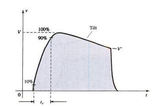
31 Square Wave Testing 61 Example 9-15: The application of a 1-mV, 5-kHz square wave to an amplifier resulted in the output waveform of Fig (a) Write the Fourier series expansion for the square wave through the ninth harmonic. (b) Determine the bandwidth of the amplifier (c) Calculate the low cutoff frequency. Home Task 62 Reading: 1. Summary 2. Equations 3. Computer analysis Problems: 1. Sec 8.2: (odd) 2. Sec 8.3: 17,18 3. Sec 8.4: 19,21 4. Sec 8.5:23,25 5. Sec 8.6: 27,29 6. Sec 8.7: Sec 8.8: 33,35,37 8. Sec 8.10: 39,41 9. Sec 8.11: Sec 8.12: Sec 8.14: Sec 8.15: 49 31
32 FET References Bolestad 2. Paynter CH 1 32
Lecture #7 BJT and JFET Frequency Response
 November 2014 Integrated Technical Education Cluster At AlAmeeria J-601-1448 Electronic Principals Lecture #7 BJT and JFET Frequency Response Instructor: Dr. Ahmad El-Banna Agenda Introduction General
UNIT I BIASING OF DISCRETE BJT AND MOSFET PART A
 UNIT I BIASING OF DISCRETE BJT AND MOSFET PART A 1. Why do we choose Q point at the center of the load line? 2. Name the two techniques used in the stability of the q point.explain. 3. Give the expression
Homework Assignment 12
 Homework Assignment 12 Question 1 Shown the is Bode plot of the magnitude of the gain transfer function of a constant GBP amplifier. By how much will the amplifier delay a sine wave with the following
Code: 9A Answer any FIVE questions All questions carry equal marks *****
 II B. Tech II Semester (R09) Regular & Supplementary Examinations, April/May 2012 ELECTRONIC CIRCUIT ANALYSIS (Common to EIE, E. Con. E & ECE) Time: 3 hours Max Marks: 70 Answer any FIVE questions All
Integrators, differentiators, and simple filters
 BEE 233 Laboratory-4 Integrators, differentiators, and simple filters 1. Objectives Analyze and measure characteristics of circuits built with opamps. Design and test circuits with opamps. Plot gain vs.
LAB 4 : FET AMPLIFIERS
 LEARNING OUTCOME: LAB 4 : FET AMPLIFIERS In this lab, students design and implement single-stage FET amplifiers and explore the frequency response of the real amplifiers. Breadboard and the Analog Discovery
5.25Chapter V Problem Set
 5.25Chapter V Problem Set P5.1 Analyze the circuits in Fig. P5.1 and determine the base, collector, and emitter currents of the BJTs as well as the voltages at the base, collector, and emitter terminals.
ELC224 Final Review (12/10/2009) Name:
 Name:") ELC224 Final Review (12/10/2009) Name: Select the correct answer to the problems 1 through 20. 1. A common-emitter amplifier that uses direct coupling is an example of a dc amplifier. 2. The frequency
ELC224 Final Review (12/10/2009) Name: Select the correct answer to the problems 1 through 20. 1. A common-emitter amplifier that uses direct coupling is an example of a dc amplifier. 2. The frequency
ECE 2201 PRELAB 6 BJT COMMON EMITTER (CE) AMPLIFIER
 AMPLIFIER") ECE 2201 PRELAB 6 BJT COMMON EMITTER (CE) AMPLIFIER Hand Analysis P1. Determine the DC bias for the BJT Common Emitter Amplifier circuit of Figure 61 (in this lab) including the voltages V B, V C and V
ECE 2201 PRELAB 6 BJT COMMON EMITTER (CE) AMPLIFIER Hand Analysis P1. Determine the DC bias for the BJT Common Emitter Amplifier circuit of Figure 61 (in this lab) including the voltages V B, V C and V
EK307 Passive Filters and Steady State Frequency Response
 EK307 Passive Filters and Steady State Frequency Response Laboratory Goal: To explore the properties of passive signal-processing filters Learning Objectives: Passive filters, Frequency domain, Bode plots
Assist Lecturer: Marwa Maki. Active Filters
 Active Filters In past lecture we noticed that the main disadvantage of Passive Filters is that the amplitude of the output signals is less than that of the input signals, i.e., the gain is never greater
PHYSICS 330 LAB Operational Amplifier Frequency Response
 PHYSICS 330 LAB Operational Amplifier Frequency Response Objectives: To measure and plot the frequency response of an operational amplifier circuit. History: Operational amplifiers are among the most widely
EXP8: AMPLIFIERS II.
 EXP8: AMPLIFIES II. Objectives. The objectives of this lab are:. To analyze the behavior of a class A amplifier. 2. To understand the role the components play in the gain of the circuit. 3. To find the
Physics 116A Fall 2000: Final Exam
 Physics 6A Fall 2000: Final Exam 2//2000 (rev. 2/0) Closed book and notes except for three 8.5 in 2 sheets of paper. Show reasoning for full credit. There are 6 problems and 200 points. Note: complex quantities
EC2205 Electronic Circuits-1 UNIT III FREQUENCY RESPONSE OF AMPLIFIERS
 EC2205 Electronic Circuits-1 UNIT III FREQUENCY RESPONSE OF AMPLIFIERS PART A (2 MARK QUESTIONS) 1. Two amplifiers having gain 20 db and 40 db are cascaded. Find the overall gain in db. (NOV/DEC 2009)
Pre-Lab. Introduction
 Pre-Lab Read through this entire lab. Perform all of your calculations (calculated values) prior to making the required circuit measurements. You may need to measure circuit component values to obtain
CHAPTER.4 :TRANSISTOR FREQUENCY RESPONSE
 CHAPTER.4 :TRANSISTOR FREQUENCY RESPONSE To understand Decibels, log scale, general frequency considerations of an amplifier. low frequency analysis - Bode plot low frequency response BJT amplifier Miller
Kent Bertilsson Muhammad Amir Yousaf
 Today s topics Analog System (Rev) Frequency Domain Signals in Frequency domain Frequency analysis of signals and systems Transfer Function Basic elements: R, C, L Filters RC Filters jw method (Complex
THE UNIVERSITY OF HONG KONG. Department of Electrical and Electrical Engineering
 THE UNIVERSITY OF HONG KONG Department of Electrical and Electrical Engineering Experiment EC1 The Common-Emitter Amplifier Location: Part I Laboratory CYC 102 Objective: To study the basic operation and
Common-Source Amplifiers
 Lab 2: Common-Source Amplifiers Introduction The common-source stage is the most basic amplifier stage encountered in CMOS analog circuits. Because of its very high input impedance, moderate-to-high gain,
EK307 Active Filters and Steady State Frequency Response
 EK307 Active Filters and Steady State Frequency Response Laboratory Goal: To explore the properties of active signal-processing filters Learning Objectives: Active Filters, Op-Amp Filters, Bode plots Suggested
Electronics Lab. (EE21338)
") Princess Sumaya University for Technology The King Abdullah II School for Engineering Electrical Engineering Department Electronics Lab. (EE21338) Prepared By: Eng. Eyad Al-Kouz October, 2012 Table of
Princess Sumaya University for Technology The King Abdullah II School for Engineering Electrical Engineering Department Electronics Lab. (EE21338) Prepared By: Eng. Eyad Al-Kouz October, 2012 Table of
EXPERIMENT 1: LOW AND HIGH FREQUENCY REGION ANALYSIS OF BJT AMPLIFIERS
 EXPERIMENT 1: LOW AND HIGH FREQUENCY REGION ANALYSIS OF BJT AMPLIFIERS Objective: In single layer common emitter amplifiers, observation of frequency dependence. Materials Transistor: 1x BC237 transistor
ESE319 Introduction to Microelectronics High Frequency BJT Model & Cascode BJT Amplifier
 High Frequency BJT Model & Cascode BJT Amplifier 1 Gain of 10 Amplifier Non-ideal Transistor C in R 1 V CC R 2 v s Gain starts dropping at > 1MHz. Why! Because of internal transistor capacitances that
(a) Current-controlled and (b) voltage-controlled amplifiers.
 Current-controlled and (b) voltage-controlled amplifiers.") Fig. 6.1 (a) Current-controlled and (b) voltage-controlled amplifiers. Fig. 6.2 Drs. Ian Munro Ross (front) and G. C. Dacey jointly developed an experimental procedure for measuring the characteristics
Fig. 6.1 (a) Current-controlled and (b) voltage-controlled amplifiers. Fig. 6.2 Drs. Ian Munro Ross (front) and G. C. Dacey jointly developed an experimental procedure for measuring the characteristics
E84 Lab 3: Transistor
 E84 Lab 3: Transistor Cherie Ho and Siyi Hu April 18, 2016 Transistor Testing 1. Take screenshots of both the input and output characteristic plots observed on the semiconductor curve tracer with the following
UNIVERSITY OF PENNSYLVANIA EE 206
 UNIVERSITY OF PENNSYLVANIA EE 206 TRANSISTOR BIASING CIRCUITS Introduction: One of the most critical considerations in the design of transistor amplifier stages is the ability of the circuit to maintain
Lab 6: MOSFET AMPLIFIER
 Lab 6: MOSFET AMPLIFIER NOTE: This is a "take home" lab. You are expected to do the lab on your own time (still working with your lab partner) and then submit your lab reports. Lab instructors will be
Mini Project 3 Multi-Transistor Amplifiers. ELEC 301 University of British Columbia
 Mini Project 3 Multi-Transistor Amplifiers ELEC 30 University of British Columbia 4463854 November 0, 207 Contents 0 Introduction Part : Cascode Amplifier. A - DC Operating Point.......................................
CHAPTER 6 Frequency Response, Bode. Plots, and Resonance
 CHAPTER 6 Frequency Response, Bode Plots, and Resonance CHAPTER 6 Frequency Response, Bode Plots, and Resonance 1. State the fundamental concepts of Fourier analysis. 2. Determine the output of a filter
SIDDHARTH GROUP OF INSTITUTIONS :: PUTTUR (AUTONOMOUS) Siddharth Nagar, Narayanavanam Road QUESTION BANK
 Siddharth Nagar, Narayanavanam Road QUESTION BANK") SIDDHARTH GROUP OF INSTITUTIONS :: PUTTUR (AUTONOMOUS) Siddharth Nagar, Narayanavanam Road 517583 QUESTION BANK Subject with Code : Electronic Circuit Analysis (16EC407) Year & Sem: II-B.Tech & II-Sem
SIDDHARTH GROUP OF INSTITUTIONS :: PUTTUR (AUTONOMOUS) Siddharth Nagar, Narayanavanam Road 517583 QUESTION BANK Subject with Code : Electronic Circuit Analysis (16EC407) Year & Sem: II-B.Tech & II-Sem
Homework Assignment 07
 Homework Assignment 07 Question 1 (Short Takes). 2 points each unless otherwise noted. 1. A single-pole op-amp has an open-loop low-frequency gain of A = 10 5 and an open loop, 3-dB frequency of 4 Hz.
ECE 231 Laboratory Exercise 6 Frequency / Time Response of RL and RC Circuits
 ECE 231 Laboratory Exercise 6 Frequency / Time Response of RL and RC Circuits Laboratory Group (Names) OBJECTIVES Observe and calculate the response of first-order low pass and high pass filters. Gain
EXPT NO: 1.A. COMMON EMITTER AMPLIFIER (Software) PRELAB:
 PRELAB:") EXPT NO: 1.A COMMON EMITTER AMPLIFIER (Software) PRELAB: 1. Study the operation and working principle of CE amplifier. 2. Identify all the formulae you will need in this Lab. 3. Study the procedure of
EXPT NO: 1.A COMMON EMITTER AMPLIFIER (Software) PRELAB: 1. Study the operation and working principle of CE amplifier. 2. Identify all the formulae you will need in this Lab. 3. Study the procedure of
Lab 4 : Transistor Oscillators
 Objective: Lab 4 : Transistor Oscillators In this lab, you will learn how to design and implement a colpitts oscillator. In part II you will implement a RC phase shift oscillator Hardware Required : Pre
Lab 6: Building a Function Generator
 ECE 212 Spring 2010 Circuit Analysis II Names: Lab 6: Building a Function Generator Objectives In this lab exercise you will build a function generator capable of generating square, triangle, and sine
BJT Circuits (MCQs of Moderate Complexity)
") BJT Circuits (MCQs of Moderate Complexity) 1. The current ib through base of a silicon npn transistor is 1+0.1 cos (1000πt) ma. At 300K, the rπ in the small signal model of the transistor is i b B C r
BJT Circuits (MCQs of Moderate Complexity) 1. The current ib through base of a silicon npn transistor is 1+0.1 cos (1000πt) ma. At 300K, the rπ in the small signal model of the transistor is i b B C r
ECE 310L : LAB 9. Fall 2012 (Hay)
") ECE 310L : LAB 9 PRELAB ASSIGNMENT: Read the lab assignment in its entirety. 1. For the circuit shown in Figure 3, compute a value for R1 that will result in a 1N5230B zener diode current of approximately
ECE 310L : LAB 9 PRELAB ASSIGNMENT: Read the lab assignment in its entirety. 1. For the circuit shown in Figure 3, compute a value for R1 that will result in a 1N5230B zener diode current of approximately
ANALOG ELECTRONIC CIRCUITS LABORATORY MANUAL (CODE: EEE - 228)
") ANALOG ELECTRONIC CIRCUITS LABORATORY MANUAL (CODE: EEE - 228) DEPARTMENT OF ELECTRONICS & COMMUNICATION ENGINEERING ANIL NEERUKONDA INSTITUTE OF TECHNOLOGY & SCIENCES (Affiliated to AU, Approved by AICTE
ANALOG ELECTRONIC CIRCUITS LABORATORY MANUAL (CODE: EEE - 228) DEPARTMENT OF ELECTRONICS & COMMUNICATION ENGINEERING ANIL NEERUKONDA INSTITUTE OF TECHNOLOGY & SCIENCES (Affiliated to AU, Approved by AICTE
LABORATORY #3 QUARTZ CRYSTAL OSCILLATOR DESIGN
 LABORATORY #3 QUARTZ CRYSTAL OSCILLATOR DESIGN OBJECTIVES 1. To design and DC bias the JFET transistor oscillator for a 9.545 MHz sinusoidal signal. 2. To simulate JFET transistor oscillator using MicroCap
Lab 9: Operational amplifiers II (version 1.5)
") Lab 9: Operational amplifiers II (version 1.5) WARNING: Use electrical test equipment with care! Always double-check connections before applying power. Look for short circuits, which can quickly destroy
Lab 9: Operational amplifiers II (version 1.5) WARNING: Use electrical test equipment with care! Always double-check connections before applying power. Look for short circuits, which can quickly destroy
Chapter 6. BJT Amplifiers
 Basic Electronic Devices and Circuits EE 111 Electrical Engineering Majmaah University 2 nd Semester 1432/1433 H Chapter 6 BJT Amplifiers 1 Introduction The things you learned about biasing a transistor
Homework Assignment 10
 Homework Assignment 10 Question 1 (Short Takes) Two points each unless otherwise indicated. 1. What is the 3-dB bandwidth of the amplifier shown below if r π = 2.5K, r o = 100K, g m = 40 ms, and C L =
EXPERIMENT 10: SINGLE-TRANSISTOR AMPLIFIERS 11/11/10
 EXPERIMENT 10: SINGLE-TRANSISTOR AMPLIFIERS 11/11/10 In this experiment we will measure the characteristics of the standard common emitter amplifier. We will use the 2N3904 npn transistor. If you have
Study of Inductive and Capacitive Reactance and RLC Resonance
 Objective Study of Inductive and Capacitive Reactance and RLC Resonance To understand how the reactance of inductors and capacitors change with frequency, and how the two can cancel each other to leave
Phy 335, Unit 4 Transistors and transistor circuits (part one)
") Mini-lecture topics (multiple lectures): Phy 335, Unit 4 Transistors and transistor circuits (part one) p-n junctions re-visited How does a bipolar transistor works; analogy with a valve Basic circuit
Mini-lecture topics (multiple lectures): Phy 335, Unit 4 Transistors and transistor circuits (part one) p-n junctions re-visited How does a bipolar transistor works; analogy with a valve Basic circuit
FET Biasing. Electronic Circuit Design ME /8/2013. Spring Chapter 2. Chapter Contents. Course Support
 Spring 2013 2 Chapter 2 ME-2401 Electronic Circuit Design 4 th Semester (Mechatronics) SZABIST, Karachi 3 Chapter Contents 4 Course Support humera.rafique@szabist.edu.pk Office: 100 Campus (404) Ext. (120)
Filters And Waveform Shaping
 Physics 3330 Experiment #3 Fall 2001 Purpose Filters And Waveform Shaping The aim of this experiment is to study the frequency filtering properties of passive (R, C, and L) circuits for sine waves, and
EE105 Fall 2015 Microelectronic Devices and Circuits. Amplifier Gain
 EE05 Fall 205 Microelectronic Devices and Circuits Prof. Ming C. Wu wu@eecs.berkeley.edu 5 Sutardja Dai Hall (SDH) 2- Amplifier Gain Voltage Gain: Current Gain: Power Gain: Note: A v v O v I A i i O i
A.C. FILTER NETWORKS. Learning Objectives
 C H A P T E 17 Learning Objectives Introduction Applications Different Types of Filters Octaves and Decades of Frequency Decibel System alue of 1 db Low-Pass C Filter Other Types of Low-Pass Filters Low-Pass
ECE4902 C Lab 5 MOSFET Common Source Amplifier with Active Load Bandwidth of MOSFET Common Source Amplifier: Resistive Load / Active Load
 ECE4902 C2012 - Lab 5 MOSFET Common Source Amplifier with Active Load Bandwidth of MOSFET Common Source Amplifier: Resistive Load / Active Load PURPOSE: The primary purpose of this lab is to measure the
ECE 3155 Experiment I AC Circuits and Bode Plots Rev. lpt jan 2013
 Signature Name (print, please) Lab section # Lab partner s name (if any) Date(s) lab was performed ECE 3155 Experiment I AC Circuits and Bode Plots Rev. lpt jan 2013 In this lab we will demonstrate basic
DEPARTMENT OF ELECTRICAL ENGINEERING AND COMPUTER SCIENCE MASSACHUSETTS INSTITUTE OF TECHNOLOGY CAMBRIDGE, MASSACHUSETTS 02139
 DEPARTMENT OF ELECTRICAL ENGINEERING AND COMPUTER SCIENCE MASSACHUSETTS INSTITUTE OF TECHNOLOGY CAMBRIDGE, MASSACHUSETTS 02139 Spring Term 2007 6.101 Introductory Analog Electronics Laboratory Laboratory
EE233 Autumn 2016 Electrical Engineering University of Washington. EE233 HW7 Solution. Nov. 16 th. Due Date: Nov. 23 rd
 EE233 HW7 Solution Nov. 16 th Due Date: Nov. 23 rd 1. Use a 500nF capacitor to design a low pass passive filter with a cutoff frequency of 50 krad/s. (a) Specify the cutoff frequency in hertz. fc c 50000
Lab #2: Electrical Measurements II AC Circuits and Capacitors, Inductors, Oscillators and Filters
 Lab #2: Electrical Measurements II AC Circuits and Capacitors, Inductors, Oscillators and Filters Goal: In circuits with a time-varying voltage, the relationship between current and voltage is more complicated
Field Effect Transistors
 Field Effect Transistors Purpose In this experiment we introduce field effect transistors (FETs). We will measure the output characteristics of a FET, and then construct a common-source amplifier stage,
, answer the next six questions.
 Frequency Response Problems Conceptual Questions 1) T/F Given f(t) = A cos (ωt + θ): The amplitude of the output in sinusoidal steady-state increases as K increases and decreases as ω increases. 2) T/F
UNIT 1 MULTI STAGE AMPLIFIES
 UNIT 1 MULTI STAGE AMPLIFIES 1. a) Derive the equation for the overall voltage gain of a multistage amplifier in terms of the individual voltage gains. b) what are the multi-stage amplifiers? 2. Describe
A GSM Band Low-Power LNA 1. LNA Schematic
 A GSM Band Low-Power LNA 1. LNA Schematic Fig1.1 Schematic of the Designed LNA 2. Design Summary Specification Required Simulation Results Peak S21 (Gain) > 10dB >11 db 3dB Bandwidth > 200MHz (
Pole, zero and Bode plot
 Pole, zero and Bode plot EC04 305 Lecture notes YESAREKEY December 12, 2007 Authored by: Ramesh.K Pole, zero and Bode plot EC04 305 Lecture notes A rational transfer function H (S) can be expressed as
Experiment EB1: FET Amplifier Frequency Response
 1: FET Amplifier Frequency Response earng Outcome O1: Expla the prciples and operation of amplifiers and switchg circuits. O2: Analyse low and high frequency response of amplifiers. O4: Analyze the operation
ANALOG FUNDAMENTALS C. Topic 4 BASIC FET AMPLIFIER CONFIGURATIONS
 AV18-AFC ANALOG FUNDAMENTALS C Topic 4 BASIC FET AMPLIFIER CONFIGURATIONS 1 ANALOG FUNDAMENTALS C AV18-AFC Overview This topic identifies the basic FET amplifier configurations and their principles of
Lab #2: Electrical Measurements II AC Circuits and Capacitors, Inductors, Oscillators and Filters
 Lab #2: Electrical Measurements II AC Circuits and Capacitors, Inductors, Oscillators and Filters Goal: In circuits with a time-varying voltage, the relationship between current and voltage is more complicated
In a cascade configuration, the overall voltage and current gains are given by:
 ECE 3274 Two-Stage Amplifier Project 1. Objective The objective of this lab is to design and build a direct coupled two-stage amplifier, including a common-source gain stage and a common-collector buffer
Course Number Section. Electronics I ELEC 311 BB Examination Date Time # of pages. Final August 12, 2005 Three hours 3 Instructor
 Course Number Section Electronics ELEC 311 BB Examination Date Time # of pages Final August 12, 2005 Three hours 3 nstructor Dr. R. Raut M aterials allowed: No Yes X (Please specify) Calculators allowed:
Electronics Prof. D. C. Dube Department of Physics Indian Institute of Technology, Delhi
 Electronics Prof. D. C. Dube Department of Physics Indian Institute of Technology, Delhi Module No # 05 FETS and MOSFETS Lecture No # 06 FET/MOSFET Amplifiers and their Analysis In the previous lecture
Experiment 8 Frequency Response
 Experiment 8 Frequency Response W.T. Yeung, R.A. Cortina, and R.T. Howe UC Berkeley EE 105 Spring 2005 1.0 Objective This lab will introduce the student to frequency response of circuits. The student will
Experiment No. 9 DESIGN AND CHARACTERISTICS OF COMMON BASE AND COMMON COLLECTOR AMPLIFIERS
 Experiment No. 9 DESIGN AND CHARACTERISTICS OF COMMON BASE AND COMMON COLLECTOR AMPLIFIERS 1. Objective: The objective of this experiment is to explore the basic applications of the bipolar junction transistor
Microelectronic Circuits - Fifth Edition Sedra/Smith Copyright 2004 by Oxford University Press, Inc.
 Feedback 1 Figure 8.1 General structure of the feedback amplifier. This is a signal-flow diagram, and the quantities x represent either voltage or current signals. 2 Figure E8.1 3 Figure 8.2 Illustrating
Homework Assignment 06
 Homework Assignment 06 Question 1 (Short Takes) One point each unless otherwise indicated. 1. Consider the current mirror below, and neglect base currents. What is? Answer: 2. In the current mirrors below,
Frequency Response of Common Emitter Amplifier
 Başkent University Department of Electrical and Electronics Engineering EEM 311 Electronics II Experiment 6 Frequency Response of Common Emitter Amplifier Aim: The aim of this experiment is to study the
School of Sciences. ELECTRONICS II ECE212A 2 nd Assignment
 School of Sciences SPRING SEMESTER 2010 INSTRUCTOR: Dr Konstantinos Katzis COURSE / SECTION: ECE212N COURSE TITLE: Electronics II OFFICE RM#: 124 (1 st floor) OFFICE TEL#: 22713296 OFFICE HOURS: Monday
Electron Devices and Circuits
 Electron Devices and Circuits (EC 8353) Prepared by Mr.R.Suresh, AP/EEE Ms.S.KARKUZHALI,A.P/EEE BJT small signal model Analysis of CE, CB, CC amplifiers- Gain and frequency response MOSFET small signal
LABORATORY MODULE. Analog Electronics. Semester 2 (2006/2007) EXPERIMENT 6 : Amplifier Low-Frequency Response
 EXPERIMENT 6 : Amplifier Low-Frequency Response") LABORATORY MODULE ENT 162 Analog Electronics Semester 2 (2006/2007) EXPERIMENT 6 : Amplifier Low-Frequency Response Name Matrix No. : : Name Matrix No. : : PUSAT PENGAJIAN KEJURUTERAAN MEKATRONIK KOLEJ
LABORATORY MODULE ENT 162 Analog Electronics Semester 2 (2006/2007) EXPERIMENT 6 : Amplifier Low-Frequency Response Name Matrix No. : : Name Matrix No. : : PUSAT PENGAJIAN KEJURUTERAAN MEKATRONIK KOLEJ
2. SINGLE STAGE BIPOLAR JUNCTION TRANSISTOR (BJT) AMPLIFIERS
 AMPLIFIERS") 2. SINGLE STAGE BIPOLAR JUNCTION TRANSISTOR (BJT) AMPLIFIERS I. Objectives and Contents The goal of this experiment is to become familiar with BJT as an amplifier and to evaluate the basic configurations
2. SINGLE STAGE BIPOLAR JUNCTION TRANSISTOR (BJT) AMPLIFIERS I. Objectives and Contents The goal of this experiment is to become familiar with BJT as an amplifier and to evaluate the basic configurations
FREQUENCY RESPONSE AND PASSIVE FILTERS LABORATORY
 FREQUENCY RESPONSE AND PASSIVE FILTERS LABORATORY In this experiment we will analytically determine and measure the frequency response of networks containing resistors, AC source/sources, and energy storage
EE-2302 Passive Filters and Frequency Response
 EE2302 Passive Filters and Frequency esponse Objective he student should become acquainted with simple passive filters for performing highpass, lowpass, and bandpass operations. he experimental tasks also
Chapter 3, Sections Electrical Filters
 Chapter 3, Sections 3.2.4-3.2.5 Electrical Filters Signals DC and AC Components - Many signals can be constructed as sums of AC and DC components: 2.5 2 1.5 2 1.5 1.5 1 2 3 4 1.5 -.5-1 1 2 3 4 = + 2.5
The Miller Approximation. CE Frequency Response. The exact analysis is worked out on pp of H&S.
 CE Frequency Response The exact analysis is worked out on pp. 639-64 of H&S. The Miller Approximation Therefore, we consider the effect of C µ on the input node only V ---------- out V s = r g π m ------------------
Week 9a OUTLINE. MOSFET I D vs. V GS characteristic Circuit models for the MOSFET. Reading. resistive switch model small-signal model
 Week 9a OUTLINE MOSFET I vs. V GS characteristic Circuit models for the MOSFET resistive switch model small-signal model Reading Rabaey et al.: Chapter 3.3.2 Hambley: Chapter 12 (through 12.5); Section
Electronics I ELEC 311/1 BB. Final August 14, hours 6
 Course Number Section Electronics I ELEC 311/1 BB Examination Date Time # of pages Final August 14, 2009 3 hours 6 Instructor(s) Dr.R. Raut M aterials allowed: No Yes X (Please specify) Calculators allowed:
Filter Design, Active Filters & Review. EGR 220, Chapter 14.7, December 14, 2017
 Filter Design, Active Filters & Review EGR 220, Chapter 14.7, 14.11 December 14, 2017 Overview ² Passive filters (no op amps) ² Design examples ² Active filters (use op amps) ² Course review 2 Example:
Experiment 2: Transients and Oscillations in RLC Circuits
 Experiment 2: Transients and Oscillations in RLC Circuits Will Chemelewski Partner: Brian Enders TA: Nielsen See laboratory book #1 pages 5-7, data taken September 1, 2009 September 7, 2009 Abstract Transient
EECS40 RLC Lab guide
 EECS40 RLC Lab guide Introduction Second-Order Circuits Second order circuits have both inductor and capacitor components, which produce one or more resonant frequencies, ω0. In general, a differential
3-Stage Transimpedance Amplifier
 3-Stage Transimpedance Amplifier ECE 3400 - Dr. Maysam Ghovanloo Garren Boggs TEAM 11 Vasundhara Rawat December 11, 2015 Project Specifications and Design Approach Goal: Design a 3-stage transimpedance
Roll No. B.Tech. SEM I (CS-11, 12; ME-11, 12, 13, & 14) MID SEMESTER EXAMINATION, ELECTRONICS ENGINEERING (EEC-101)
 MID SEMESTER EXAMINATION, ELECTRONICS ENGINEERING (EEC-101)") F:/Academic/22 Refer/WI/ACAD/10 SHRI RAMSWAROOP MEMORIAL COLLEGE OF ENGG. & MANAGEMENT (Following Paper-ID and Roll No. to be filled by the student in the Answer Book) PAPER ID: 3301 Roll No. B.Tech. SEM
F:/Academic/22 Refer/WI/ACAD/10 SHRI RAMSWAROOP MEMORIAL COLLEGE OF ENGG. & MANAGEMENT (Following Paper-ID and Roll No. to be filled by the student in the Answer Book) PAPER ID: 3301 Roll No. B.Tech. SEM
Basic electronics Prof. T.S. Natarajan Department of Physics Indian Institute of Technology, Madras Lecture- 17. Frequency Analysis
 Basic electronics Prof. T.S. Natarajan Department of Physics Indian Institute of Technology, Madras Lecture- 17 Frequency Analysis Hello everybody! In our series of lectures on basic electronics learning
EE301 ELECTRONIC CIRCUITS CHAPTER 2 : OSCILLATORS. Lecturer : Engr. Muhammad Muizz Bin Mohd Nawawi
 EE301 ELECTRONIC CIRCUITS CHAPTER 2 : OSCILLATORS Lecturer : Engr. Muhammad Muizz Bin Mohd Nawawi 2.1 INTRODUCTION An electronic circuit which is designed to generate a periodic waveform continuously at
Core Technology Group Application Note 6 AN-6
 Characterization of an RLC Low pass Filter John F. Iannuzzi Introduction Inductor-capacitor low pass filters are utilized in systems such as audio amplifiers, speaker crossover circuits and switching power
Document Name: Electronic Circuits Lab. Facebook: Twitter:
 Document Name: Electronic Circuits Lab www.vidyathiplus.in Facebook: www.facebook.com/vidyarthiplus Twitter: www.twitter.com/vidyarthiplus Copyright 2011-2015 Vidyarthiplus.in (VP Group) Page 1 CIRCUIT
Electronic PRINCIPLES
 MALVINO & BATES Electronic PRINCIPLES SEVENTH EDITION Chapter 9 AC Models Topics covered in Chapter 9 Base-biased amplifier Emitter-biased amplifier Small-signal operation AC beta AC resistance of the
UNIVERSITY OF NORTH CAROLINA AT CHARLOTTE Department of Electrical and Computer Engineering
 UNIVERSITY OF NORTH CAROLINA AT CHARLOTTE Department of Electrical and Computer Engineering EXPERIMENT 7 BJT AMPLIFIER CONFIGURATIONS AND INPUT/OUTPUT IMPEDANCE OBJECTIVES The purpose of this experiment
Dev Bhoomi Institute Of Technology Department of Electronics and Communication Engineering PRACTICAL INSTRUCTION SHEET
 Dev Bhoomi Institute Of Technology Department of Electronics and Communication Engineering PRACTICAL INSTRUCTION SHEET LABORATORY MANUAL EXPERIMENT NO. ISSUE NO. : ISSUE DATE: REV. NO. : REV. DATE : PAGE:
Boise State University Department of Electrical and Computer Engineering ECE 212L Circuit Analysis and Design Lab
 Objectives Boise State University Department of Electrical and Computer Engineering ECE L Circuit Analysis and Design Lab Experiment #0: Frequency esponse Measurements The objectives of this laboratory
PURPOSE: NOTE: Be sure to record ALL results in your laboratory notebook.
 EE4902 Lab 9 CMOS OP-AMP PURPOSE: The purpose of this lab is to measure the closed-loop performance of an op-amp designed from individual MOSFETs. This op-amp, shown in Fig. 9-1, combines all of the major
Dev Bhoomi Institute Of Technology Department of Electronics and Communication Engineering PRACTICAL INSTRUCTION SHEET REV. NO. : REV.
 Dev Bhoomi Institute Of Technology Department of Electronics and Communication Engineering PRACTICAL INSTRUCTION SHEET LABORATORY MANUAL EXPERIMENT NO. 1 ISSUE NO. : ISSUE DATE: July 2010 REV. NO. : REV.
Lecture 16 Date: Frequency Response (Contd.)
") Lecture 16 Date: 03.10.2017 Frequency Response (Contd.) Bode Plot (contd.) Bode Plot (contd.) Bode Plot (contd.) not every transfer function has all seven factors. To sketch the Bode plots for a generic
Lecture 16 Date: 03.10.2017 Frequency Response (Contd.) Bode Plot (contd.) Bode Plot (contd.) Bode Plot (contd.) not every transfer function has all seven factors. To sketch the Bode plots for a generic
Homework Assignment 07
 Homework Assignment 07 Question 1 (Short Takes). 2 points each unless otherwise noted. 1. A single-pole op-amp has an open-loop low-frequency gain of A = 10 5 and an open loop, 3-dB frequency of 4 Hz.
Figure 1: JFET common-source amplifier. A v = V ds V gs
 Chapter 7: FET Amplifiers Switching and Circuits The Common-Source Amplifier In a common-source (CS) amplifier, the input signal is applied to the gate and the output signal is taken from the drain. The
IFB270 Advanced Electronic Circuits
 IFB270 Advanced Electronic Circuits Chapter 9: FET amplifiers and switching circuits Prof. Manar Mohaisen Department of EEC Engineering Review of the Precedent Lecture Review of basic electronic devices