Electromagnetic Compatibility Test Report
|
|
|
- Erik Marsh
- 6 years ago
- Views:
Transcription


1 Electromagnetic Compatibility Test Report Test Report No: SLR Issued on: July 02, 2014 Product Name HummingBoard (With AC/DC Adaptor FJ-SW E) Tested According to EN 55024: 2010, 55022:2010:2011 AS/NZS CISPR 22: 2009+A1:2010 Tests Performed for Solid-run 3 Plane, Tafen Tower Tel: QualiTech EMC Laboratory 30 Hasivim Street,P.O.Box 7500 Petah-Tikva, , Israel Tel: Fax:
2 The information contained herein is the property of QualiTech, EMC Lab and is supplied without liability for errors or omissions. The copyright for this document vests in QualiTech, EMC Lab. All rights reserved. This Test Report may not be reproduced, by any method, without the written permission of the QualiTech, EMC Lab. If and when such permission is granted, the report must be reproduced only in the full format. Test Personnel Tests Performed By: Michael Shtier Report Prepared By: Bina Talkar Report Approved By: Rami Nataf EMC Lab. Manager QualiTech EMC Laboratory Solid-run Page 2 of 59 Humming Board
3 Test Report Details: Test commencement date: Test completion date: Customer s Representative: Kossay Omary Issued on: Assessment Information: This report contains an assessment of the EUT against Electromagnetic Compatibility based upon tests carried out on the samples submitted. The results contained in this report relate only to the items tested. Manufactured products will not necessarily give identical results due to production and measurement tolerances. QualiTech, EMC Lab does not assume responsibility for any conclusion and generalization drawn from the test results with regards to other specimens or samples of type of the equipment represented by test item. The EUT was setup and exercised using the configuration, modes of operation and arrangements defined in this report only. Modifications: Modifications made to the EUT None Modifications made to the Test Standard None Solid-run Page 3 of 59 Humming Board
4 Summary of Compliance Status The EUT was tested according to the following test methods. Test results are given in full in sections Emission Tests Test type Test Method Class applied Frequency Range Test results Radiated Emission EN55022 B 30MHz 1GHz Comply EN55022 B 1GHz 6GHz Comply Conducted Emission on 230 VAC EN55022 B 150kHz 30MHz Comply Conducted Emission on Ethernet EN55022 B 150kHz 30MHz Comply Harmonic current emission EN Hz to harmonic order 40 Comply Voltage Fluctuations & flicker EN Hz Comply Immunity Tests Test type Applied on Test Method Frequency Range/ application type Test level Performance Criteria applied Test results ESD Enclosure EN Contact 4kV B Comply Air 8kV B Comply 80 MHz 800MHz 3V/m A Comply 800MHz 960MHz 10V/m A Comply Radiated Immunity System EN MHz 1GHz 3V/m A Comply 1.4GHz 2GHz 10V/m A Comply 2GHz 2.7GHz 3V/m A Comply EFT 230 VAC - 1kV A Comply EN Ethernet - 0.5kV A Comply Line to Line 1kV A Comply 230 VAC EN Surge Line to Earth Not applicable (No GND) Ethernet EN Not applicable (cable length less than 10m) Conducted Immunity 230 VAC 150kHz 80MHz 3Vrms A Comply EN Ethernet 150kHz 80MHz 3Vrms A Comply Voltage dips and short interruptions 230 VAC EN Hz 100%,60%,30% B & C Comply Solid-run Page 4 of 59 Humming Board
5 Table of Contents 1. GENERAL Purpose: Referenced documents: Description of the EUT system: General Description: EUT Configuration: EUT Cards/Modules List: Cables Identification: Clock Frequencies Table: Method of Performance verification: EUT Pass/Fail criteria for immunity tests: TEST FACILITY & UNCERTAINTY OF MEASUREMENT Accreditation/ Registration reference: Test Facility description Uncertainty of Measurement: ELECTRIC FIELD EMISSION MEASUREMENTS CONDUCTED EMISSION MEASUREMENTS IMMUNITY TO ELECTROSTATIC DISCHARGE IMMUNITY TO RADIATED ELECTROMAGNETIC FIELD IMMUNITY TO ELECTRICAL FAST TRANSIENTS (EFT) IMMUNITY TO VOLTAGE SURGE IMMUNITY TO CONDUCTED RF STRESS IMMUNITY TO VOLTAGE DIPS, SHORT INTERRUPTIONS & VOLTAGE VARIATIONS HARMONIC CURRENT EMISSION MEASUREMENTS VOLTAGE FLUCTUATIONS AND FLICKER MEASUREMENTS APPENDIX Solid-run Page 5 of 59 Humming Board
6 1. General 1.1. Purpose: The purpose of this report is to show compliance to Electromagnetic Emission and Immunity requirements outlined in the referenced specifications. This report serves as the basis for the Declaration of Conformity Referenced documents: Note: Latest versions of the following standards were applied according to the Official Journal: EN EN ANSI C63.4 CISPR 22: AS/NZS CISPR 22 EN EN EN EN EN EN EN EN Limits and methods of measurement for Conducted and Radiated Emissions of information technology equipment Immunity characteristics-limits and methods of measurements American National standard for Methods of measurement of Radio-Noise Emissions from Low- Voltage Electrical and Electronic Equipment in the range of 9kHz to 40GHz Information Technology Equipment Radio disturbance characteristics - Limits and Methods of Measurement. Electrostatic Discharge (ESD) Immunity test Electro magnetic compatibility (EMC), Section 3: Radiated, radio frequency, electromagnetic field immunity IEC test Electro magnetic compatibility (EMC), Section 4: Electrical fast transient/burst immunity test Electromagnetic compatibility (EMC), Section 5: Surge immunity test Electromagnetic compatibility (EMC), Section 6: Immunity to conducted disturbances, induced by radio- frequency fields Limits for Harmonic Current Emission for equipment with rated current up to and including 16A per phase Voltage Dips, short Interruptions and Voltage Variations Immunity Tests Limits for Voltage Fluctuations and Flicker in low-voltage IEC supply for equipment with rated current up to and including 16A Solid-run Page 6 of 59 Humming Board
7 1.3. Description of the EUT system: General description of the EUT, configuration used for Emission and Immunity testing, and the method of performance verification were defined by the manufacturer. The acceptance performance criterion was declared by the manufacturer General Description: The HummingBoard is a credit card sized board computer servicing targeting DIY (Do It Yourself) customers and OEM business customers who embed the HummingBoard in their own products. The HummingBoard connects to a TV via its HDMI output; it connects to the internet via a wired Ethernet; has Two USB-2.0 host interfaces, an analog audio connector and an SPDIF output for connection to a home theater system, infra-red receiver and msata connection for local sata storage EUT Configuration: EUT Configuration for Emissions & Immunity Testing: Solid-run Page 7 of 59 Humming Board
8 EUT Cards/Modules List: No Hardware Component Manufacturer s Catalog Number Serial Number Hardware Revision Quantity 1 SR-uSOM-MX6 Internal module N/A CARRIER ONE Board Internal module N/A Cables Identification: Port/Cable EUT Type UTP/STP/Multipairs Coaxial shielded Environment class indoor /outdoor Nominal length [m] Tested Length [m] # of ports/boards available # of ports/ boards connected Tested cable/ port connection From Tested cable/port connection To DC Power Unshielded Indoor AC/DC power adapter AC mains HDMI Shielded Indoor EUT Monitor Ethernet Shielded Indoor > EUT Ethernet Switch USB-2.0 Unshielded Indoor EUT Keyboard USB-2.0 Unshielded Indoor EUT Mouse Clock Frequencies Table: Frequency [MHz] SR-uSOM-MX6 CARRIER ONE Board SR-uSOM-MX6 Location Internal module Internal module Internal module Solid-run Page 8 of 59 Humming Board
9 Method of Performance verification: During the test, the EUT was connected to an Ethernet switch and was monitoring Ethernet link status. The EUT was connected to Keyboard and Mouse via USB and was monitoring status. In addition the EUT was refreshing the display continuously to guarantee proper display and report observed failures EUT Pass/Fail criteria for immunity tests: General performance criteria: Performance Criterion A: The EUT shall continue to operate as intended. No degradation of performance or loss of functionality is allowed below a performance level specified by the manufacturer. Normal Performance for criteria A is specified as: - EUT must maintain network connectivity. - No USB or Keyboard functionality abruptions - No interference in the display. Performance Criterion B: The EUT shall continue to operate as intended after the test. No degradation of performance or loss of functionality is allowed below a performance level specified by the manufacturer. During the exposure to electromagnetic phenomenon, degradation of performance is, however allowed. No change of actual operation state or stored data is allowed. Minimum performance level for criteria B is specified as: - Momentary loss of network connection acceptable - Momentary loss of USB Keybord or Mouse connection acceptable - Momentary loss of display visibility is acceptable. Performance Criterion C: Temporary loss of functionality is allowed provided the function is self- recoverable or can be restored by the operation of the controls. Performance Criterion R: The equipment shall withstand the test without damage or other disturbance (such as corruption of software or disoperation of fault protection facilities) and shall operate properly within specified limits after the transient electromagnetic stress has ceased. It is not necessary to operate properly while the test condition is present. The exposure may cause the operation of fuses or other specified devices, which have to be replaced or reset before normal operation is restored. Solid-run Page 9 of 59 Humming Board
10 2. Test Facility & Uncertainty of Measurement 2.1. Accreditation/ Registration reference: - A2LA Certificate Number: Test Facility description The tests were performed at the EMC Laboratory, QualiTech Division, ECI Telecom Address: 30, Hasivim Street, Petah Tikva, Israel. Tel: m Anechoic Chamber: Two 3m-screened chambers are used in two configurations: the semi-anechoic chamber for Radiated Emission measurements and the full-anechoic chamber for Radiated Immunity tests. Semi Anechoic Configuration: Measurement distance 3m Chamber dimensions 9.5m x 6.5m x 5.2m Antenna height Shielding Effectiveness Absorbing material Normalized Site Attenuation measured at 5 positions Transmission Loss measured at 5 positions, at 1.5m height Full-Anechoic Configuration: Measurement distance Chamber dimensions Antenna height Shielding Effectiveness Absorbing material Field Uniformity to EN m Magnetic field 80dB at 15 khz 90dB at 100 khz Electric field 120dB from 1MHz to 1GHz 110dB from 1GHz to 10GHz Ferrite tiles on the walls and ceiling Emerson and Cuming absorbing material in selected positions on the walls 3.9dB, 30MHz to 200MHz 3dB, 200MHz to 1000MHz 3dB, 1GHz to 18GHz 3m 7m x 4m x 3m 1.55m at Horizontal & Vertical polarizations Magnetic field 80dB at 15 khz 90dB at 100 khz Electric field 120dB from 1MHz to 1GHz 110dB from 1GHz to 10GHz Ferrite tiles on the walls and ceiling Emerson and Cuming absorbing material in selected positions on the walls and floor 3dB 80MHz to 18GHz Solid-run Page 10 of 59 Humming Board
11 2.1. Uncertainty of Measurement: The data and results referenced in this document are true and accurate. The reader is cautioned that there may be errors within the calibration limits of the equipment and facilities. The measurement uncertainty was calculated for all measurements listed in this test report according to CISPR Specification for radio disturbance and immunity measuring apparatus and methods Part 4-2: Uncertainties, statistics and limit modelling Uncertainty in EMC measurements. Furthermore, component and process variability of devices similar to that tested may result in additional deviation. The manufacturer has the sole responsibility of continued compliance of the device. Test Name Range Expanded U lab Uncertainty U CISPR Uncertainty 30MHz 200MHz, Horiz. Polar. ± 4.77 db ± MHz 200MHz, Ver. Polar. ± 4.90 db ±5.17 Radiated Emission 200MHz 1000MHz, Horiz. Polar. ± 4.96 db ± MHz 1000MHz, Vert. Polar. ± 6.15 db ± GHz -6.0GHz ± 4.33 db ± GHz-18.0GHz ± 4.75 db ±5.48 Conducted Emission 9 khz 150 khz ± 3.47 db ± khz 30MHz ± 3.18 db ±3.44 Note: QualiTech EMC labs expanded measurement instrumentation has less uncertainty than the industry norm and compliance is deemed to occur as no measured disturbance exceeds the disturbance limit. Note: The reported expanded uncertainty is based on a standard uncertainty multiplied by a coverage factor of k=2, providing a level of confidence of approximately 95%. Solid-run Page 11 of 59 Humming Board
12 3. Electric Field Emission Measurements Date of Test: Relative Humidity: 48.2% Ambient Temperature: 23.2 C Atmospheric Pressure: hpa Test performed by: Michael Shtier Test Method: EN55022 Limits: 30MHz to 1GHz frequency range: Frequency [MHz] QP Limit [db V /m] [Class A] QP Limit [db V /m] [Class B] Above 1GHz frequency range: Frequency [MHz] Class A Class B AVR Limit [db V m] Peak Limit [db V /m] AVR Limit [db V m] Peak Limit [db V /m] Test Procedure: Measurements were performed at a 3-meter measurement distance in the semi-anechoic chamber in order to evaluate the radiated electromagnetic interference characteristics of the EUT. The EUT was placed on a non-metallic table, 0.8m above the turntable, was configured, arranged and operated in a manner consistent with typical application and load conditions. The test program of exercising the equipment ensured that various parts of the EUT were exercised to permit detection of all EUT disturbances. An appropriate antenna depending upon the frequency range was used. While the turntable was being rotated, the height of the antenna was varied from 1 to 4m for the frequency range of 30MHz to 1GHz, and was fixed at a height of 1m for frequencies above 1GHz. The highest radiated emission was detected by manipulating the system cables to the worst-case position. This process was repeated for both antenna polarizations. The amplitudes of worst-case emission were measured with the QP detector or Peak detector according to the frequency range, using resolution-bandwidth per CISPR16-1. List of Test Equipment: Refer to Appendix A for calibration dates. Semi Anechoic Chamber, 9.5m [L] x 6.5m [W] x 5.2m [H] HP8546A, CISPR16 EMI Receiver HP8593EM EMC Analyzer Teseq CBL 6141B, Billog Antenna A.R.A,DRG-118/A, Double Ridge Guide Horn antenna Pre-Amplifier, MiTeq MF-50-5D P-6W Solid-run Page 12 of 59 Humming Board
13 Test Details: Interference Frequency Range Measurement Means Test Setup No. Photograph No. Plot Nos. Electric Field 30MHz 6GHz Bilog & Double Ridge Guide Horn antenna Fig.3.1 & Fig.3.2 Photo Test Results: Table 3.1: Frequency range 30MHz 1GHz Frequency [MHz] Ant. Type Ant. Pol. Ant. Pos. [cm] Turn-table Azimuth [ ] Radiated Emission db( V/m) Limit at 3m db( V/m) Margin [db] Pass/ Fail Bilog V Pass Bilog V Pass Bilog V Pass Bilog V Pass Bilog H Pass Bilog H Pass Note: Radiated Emission [db V/m] = measured [db V] + Correction-factor [db(1/m)] Correction Factor = Antenna factor + Cable Loss Table 3.2: Frequency range 1GHz 6GHz Frequency [MHz] Ant. Type Ant. Pol. Ant. Pos. [cm] Turn-table Azimuth [ ] Radiated Emission db( V/m) Limit at 3m db( V/m) Margin [db] Pass/ Fail All Average readings at least 10 db below the limit Pass Note: Radiated Emission [db V/m] = measured [db V] + Correction-factor [db(1/m)] Correction Factor = Antenna factor + Cable Loss-Gain Summary: Frequency Range Test method reference Class Limits applied Test Results Pass/ Fail 30MHz 1GHz EN55022, Sec. 8 & 10 B Tab. 3.1 Pass 1GHz 6GHz ANSI C B Tab. 3.2 Pass Solid-run Page 13 of 59 Humming Board
14 Plot 3.1: Horizontal Polarization, 30MHz-1GHz Plot 3.2: Vertical Polarization, 30MHz-1GHz Solid-run Page 14 of 59 Humming Board

15 Plot 3.3: Horizontal Polarization, 1GHz-2.9GHz Plot 3.4: Vertical Polarization, 1GHz-2.9GHz Solid-run Page 15 of 59 Humming Board

16 Plot 3.5: Horizontal Polarization, 2.9GHz-6GHz Plot 3.6: Vertical Polarization, 2.9GHz-6GHz Solid-run Page 16 of 59 Humming Board
17 Figure 3.1: Setup for Radiated Emission Testing - 30MHz 1GHz Frequency Range Semi-Anechoic Chamber 9.5m x6.5 m x5.2 m Antenna Mast 1-4m Antenna Biconical/LogPeriodic EUT Turntable EMI Receiver 3m TV Camera Antenna Mast & Turntable Controller Deisel F/O F/O EUT Monitoring Operation Control TV Camera Control ANSI/IEEE488 Solid-run Page 17 of 59 Humming Board
18 Figure 3.2: Setup for Radiated Emission Testing 1GHz 6GHz Frequency Range Semi-Anechoic Chamber 9.5m x 6.5m x 5.2m Pre-Amplifier EMC Analyzer Antenna Double Ridge Guide EUT Turntable 3m TV Camera Antenna Mast & Turntable Controller Deisel F/O EUT Monitoring Operation Control TV Camera Control ANSI/IEEE 488 Solid-run Page 18 of 59 Humming Board
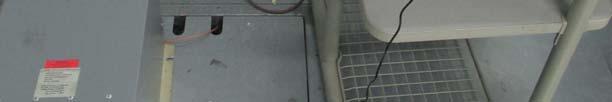
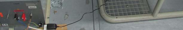
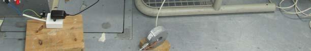
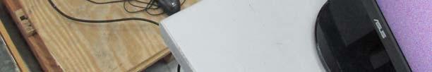
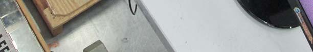
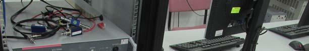
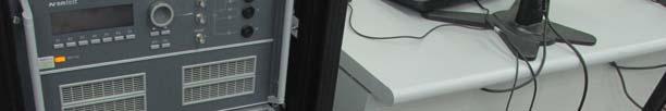
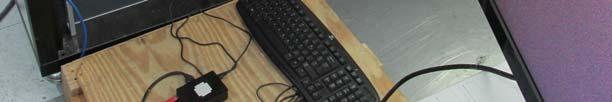
19 Photograph 3.1: Radiated Emission Testing Photograph 3.2: Radiated Emission Testing Solid-run Page 19 of 59 Humming Board
20 4. Conducted Emission Measurements Date of Test: Relative Humidity: 48.2% Ambient Temperature: 23.5 C Atmospheric Pressure: hpa Test performed by: Michael Shtier Test Method: EN55022 Limits: Power Supply Port: Class B Frequency [MHz] QP Limits [db V] Average to to Telecommunication ports and Signal Lines: Class B Frequency [MHz] Voltage Limits [db V] Current Limits [db A] QP Average QP Average to to to to Test Procedure: The measurements were performed on the line under test in a 4m x 3m x 3m screened enclosure by means of an Impedance Stabilization Network (ISN) bonded to the ground plane and connected to the spectrum analyzer. The EUT was placed on a non-metallic table, 0.8m above the ground reference plane and was configured, arranged and operated in a manner consistent with typical application and load conditions. Normal performance of the EUT was verified. Conducted common mode (asymmetric mode) disturbance at the tested port was investigated in the appropriate frequency range using the resolution-bandwidth per CISPR16-1, Table 7, and QP and Average readings were taken. Worst-case results were recorded. List of Test Equipment: Refer to Appendix A for calibration dates. Screened Enclosure 4m x 3m x 3m HP8546A, CISPR16 EMI Analyzer HP11947A, Transient Limiter Fischer 50/ , LISN Fischer,Universal Telecom, ISN F Fischer F35A Current Probe Fischer F-203 I-32 EM Clamp Solid-run Page 20 of 59 Humming Board
21 Test Details: Port under Test Measured at Test method reference Test Setup No. Photograph No. Plot Nos. 230 VAC AC line Sec & 9.5 Fig. 4.1 Photo Ethernet Ethernet port Sec & C1.2 Fig. 4.2 Photo Test Results: Table 4.1: Power Supply port: Phase Lead Frequency [MHz] Measured Result [db V] Limit [db V] Margin [db] QP AVR QP AVR QP AVR Pass/Fail Pass Pass Pass Pass Pass Pass Neutral Lead Frequency [MHz] Measured Result [db V] Limit [db V] Margin [db] QP AVR QP AVR QP AVR Pass/Fail Pass Pass Pass Pass Pass Pass Solid-run Page 21 of 59 Humming Board
22 Table 4.2: Current measurement results - Ethernet Frequency [MHz] Measured Result [db A] Limit [db A] Margin [db] QP AVR QP AVR QP AVR Pass/Fail Pass Pass Pass Pass Pass Pass Summary: Port under Test Measurement Means Class Limits applied Frequency Range Test Results Pass/ Fail 230 VAC LISN B 150kHz 30MHz Tab. 4.1 Pass Ethernet Current Probe B 150kHz 30MHz Tab. 4.2 Pass Solid-run Page 22 of 59 Humming Board
23 Plot 4.1: Power Supply Ports, 150kHz 30MHz, Phase Lead Plot 4.2: Power Supply Ports, 150kHz 30MHz, Neutral Lead Solid-run Page 23 of 59 Humming Board
24 Plot 4.3: 150kHz 30MHz, Ethernet, Solid-run Page 24 of 59 Humming Board

25 Figure 4.1: Setup for Conducted Emission Testing on AC Power Supply Port Screened Enclosure LISN AC /DC Supply EUT 40cm min to the wall 220VAC P N 50 Termination bonded to Ground Plane 80cm 80cm cable length 1m non-metallic table EMI Receiver metal floor3 mx4m Operation Control ANSI/IEEE488 HP E7515A S/W Solid-run Page 25 of 59 Humming Board
26 Figure 4.2: Setup for Conducted Emission Testing on Ethernet Screened Enclosure 40cm min to the wall Ferrites Current Probe 10cm EUT screen 150ohm 10cm non-metallic table 40cm 50cm metal floor3 mx4m to AE, or cables looped back EMI Receiver 10cm insulation support Operation Control ANSI/IEEE488 Solid-run Page 26 of 59 Humming Board


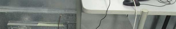
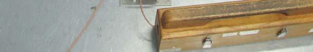
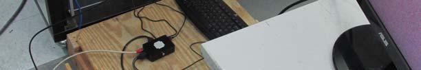
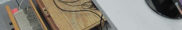
27 Photograph 4.1: Conducted Emission testing on AC Power Supply Port Solid-run Page 27 of 59 Humming Board


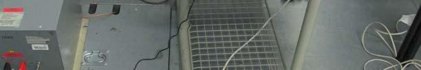

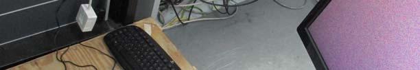
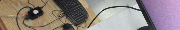
28 Photograph 4.2: Conducted Emission testing on Ethernet Solid-run Page 28 of 59 Humming Board
29 5. Immunity to Electrostatic Discharge Date of Test: Relative Humidity: 48.1% Ambient Temperature: 23.4 C Atmospheric Pressure: hpa Test performed by: Michael Shtier Test Method: EN according to EN Test Voltage: Type of Application Test Voltage # of Discharges each polarity Performance Criteria Contact Discharge 4 kv 25 B Air Discharge 8 kv 10 B Test Procedure: Electrostatic Discharge tests were performed on a ground reference plane 3m x 3m wide. The EUT was placed on a wooden table 0.8m high, standing on the ground reference plane. A horizontal coupling plane (HCP), 1.6m x 0.8m, was placed on the table underneath the EUT, and the EUT was isolated from the coupling plane by an insulating support 0.5mm thick. The HCP was connected to the ground reference plane by a bleed resistor lead. The EUT was placed on the HCP with its front face 10cm from the edge of the plane, and configured, arranged and operated in a manner consistent with typical application and load conditions. The cables were taken away from the test area separated from the HCP by 5cm and draped off the HCP as necessary. Normal performance of the EUT was verified. Direct and air application: For pre-selected points, 10 single Contact discharges in both positive and negative polarities, were applied with at least 1sec time interval between successive discharges. Discharges were applied to surfaces and metal points which are accessible during normal usage. Inside the EUT, only the points and surfaces, which have to be accessed during maintenance, were included. The same procedure was repeated for air discharges on non- metallic parts or insulating surfaces. Indirect application: Ten single discharges, in both positive and negative polarities, were applied to the HCP on each side of the EUT. The same procedure was repeated with the vertical coupling plane VCP (connected to the ground reference plane by a bleed resistor lead) on each side of the EUT such that the face of the EUT was completely illuminated. For air discharges, voltage levels were increased gradually from 2kV until the maximum severity level was reached, for each polarity. During the test, the EUT operation was monitored to verify the required Performance Criteria. List of Test Equipment: Refer to Appendix A for calibration date. Noiseken, ESS-2000 Discharge Simulator Solid-run Page 29 of 59 Humming Board
30 Test Details: Test Setup No. Photograph No. Fig. 5.1 Fig. 5.2 Test Results: Type of discharge Points of Discharge Discharge Voltage # of Discharges at each polarity Performance Criteria applied BER/ # of errors Pass/ Fail Contact Discharge Air Discharge EUT 4kV 25 B None Pass VCP 4kV 25 A None Pass HCP 4kV 25 A None Pass EUT 8kV 10 B None Pass Figure 5.1: Setup for Electrostatic Discharge Test 100cm min to the walls 0.1m Mains Supply EUT VCP Insulation Support 0.5 mm HCP 80 cm 470k 470k non-metallic table 1.6m x 0.8m Ground Reference Plane 3m x3m Solid-run Page 30 of 59 Humming Board
31 Figure 5.2: Electrostatic Discharge Map Contact Electrostatic Discharge applied at Air Electrostatic Discharge applied at spots spots Solid-run Page 31 of 59 Humming Board
32 Electrostatic Discharge Map Solid-run Page 32 of 59 Humming Board
33 6. Immunity to Radiated Electromagnetic Field Date of Test: Relative Humidity: 48.2% Ambient Temperature: 23.2 C Atmospheric Pressure: hpa Test performed by: Michael Shtier Test Method: EN according to EN Test Levels: Frequency Range Test Level Performance Criteria 80MHz 1GHz, 80% AM, 1 khz sine Emphasis of frequencies 80, 120, 160, 230,434,460,600, 863,900 3V/m A Clock frequencies See Sec V/m A Test Procedure: The EUT was placed in a full-anechoic chamber on a non-conductive table 0.8m above the absorbing ground plane, and was configured, arranged and operated in a manner consistent with typical application and load conditions. Normal performance of the EUT was verified. The EUT with its door open was positioned parallel to the pre-calibrated uniform area at a distance of 3m from the transmitting antenna. The frequency range was swept in steps of 1% with 1KHz sine-wave 80% Amplitude modulated or 200Hz square wave 50% pulse modulated, according to the frequency range, with a dwell time of 1 sec. A list of clock and sensitive frequencies were analyzed separately if made available. Special exercising S/W was used in order to precisely generate the required electromagnetic field based on the calibrated field uniformity data. All tests were performed four times, with the antenna facing each of the four sides of the EUT. Each test was performed for both, horizontal and vertical antenna polarization During the tests, the EUT and external equipment were monitored to verify normal functional performance. List of Test Equipment: Refer to Appendix A for calibration dates. IFI 2025 RF Signal Generator Agilent,83732B, Signal generator Boonton 4230 Power Meter Boonton Power Sensor Anechoic Chamber 7m x 4m x 3m AR100W100, 30MHz-1GHz Wideband Linear RF Amplifier Werlaton C3910, 30MHz-1GHz Directional Coupler EMCO 3142, BiLog Antenna Ophir GRF5061, 0.8 GHz-4.2 GHz RF Amplifier AR DC7144, 0.8 GHz 4.2 GHz Directional Coupler Amplifier Research, E-Field Probe (80MHz-40GHz), FP5080 Solid-run Page 33 of 59 Humming Board
34 Test Details: Frequency range Radiating Antenna Test Setup No. Photograph No. 80MHz 800MHz 80% AM, 1 khz sine 800MHz 960MHz 80% AM, 1 khz sine 960 MHz 1GHz 80% AM, 1 khz sine 1400 MHz 2000 MHz 80% AM, 1 khz sine 2000 MHz MHz 80% AM, 1 khz sine Clock frequencies See Sec Bilog Fig 6 Photo.6 Test Results: Frequency range Test Level* BER/ # of errors Performance Criteria applied Pass/ Fail 80MHz 800MHz 80% AM, 1 khz sine 3V/m None A Pass 800MHz 960MHz 80% AM, 1 khz sine 10V/m None A Pass 960 MHz 1GHz 80% AM, 1 khz sine 3V/m None A Pass 1400 MHz 2000 MHz 80% AM, 1 khz sine 10V/m None A Pass 2000 MHz MHz 80% AM, 1 khz sine 3V/m None A Pass Clock frequencies See Sec V/m None A Pass * Increased stress applied according to customer s requirements. Solid-run Page 34 of 59 Humming Board
35 Figure 6: Setup for Radiated Immunity Test RF Signal Generator Marconi 2024 Anechoic Chamber 7m x 4m x 3m Uniform Field Power Amplifier AR100W100 Directional Coupler Wearlton C3910 BiLog Antenna EUT Power Meter Boonton 4320 TV Camera 3m Isotropic E -Field Probe AR FP dB Attenuator f/o link for chamber calibration Field Probe Monitor FM FP-5004 Calibration and Operation Control EUT Monitoring TV Camera Control ANSI/IEEE 488 Calibration and Operation Software CIS 9942 Solid-run Page 35 of 59 Humming Board
36 Photograph 6: Radiated Immunity Test Solid-run Page 36 of 59 Humming Board
37 7. Immunity to Electrical Fast Transients (EFT) Date of Test: Relative Humidity: 48.3% Ambient Temperature: 23.4 C Atmospheric Pressure: hpa Test performed by: Michael Shtier Test Method: EN according to EN Test Levels: Power Supply Port: Power Supply leads Peak Voltage [kv] Test Duration Performance Criteria 230 VAC 1 60sec B Telecommunication ports and Signal Lines: Test Procedure: Signal Line Peak Voltage [kv] Test Duration Performance Criteria Ethernet sec B Electrical Fast Transient/Burst Tests were performed on a ground reference plane 3m x 3m wide. The EUT was placed on a table 0.8m above the ground reference plane, and was configured, arranged and operated in a manner consistent with typical application and load conditions. Normal functional performance of the EUT was verified. Fast transients/burst voltage at a repetition rate of 5 khz was applied between the reference plane and the signal lines by means of a Capacitive Coupling Clamp, and between the ground reference plane and each of the power supply terminals, AC or DC, and protective earth (PE) terminal by means of a Coupling/Decoupling Network (CDN). Every coupling mode was applied for 1minute in each polarity. The Fast transients/burst generator and CDN were bonded to the reference plane. The distance between the EUT and the coupling network or clamp was 1m or less. Clear distance of 0.5m was kept from the EUT to all other conducting structures. All cables, including the one being tested, were separated by 10cm from the ground reference plane. During the tests, the EUT and external equipment were monitored to verify the required performance criteria. List of Test Equipment: Refer to Appendix A for calibration dates. EMTest, EFT Generator, EFT 500 N8 EMTest,Coupling/Decoupling network for burst and surge, CNI 503 A18/ 32A IP4A Capacitive Coupling Clamp Solid-run Page 37 of 59 Humming Board
38 Test Details: Supply/Signal line/port under Test Test applied at Coupling Means Test Setup No. Photograph No. Test Results: 230 VAC AC line CDN Fig.7.1 Photo.7.1 Ethernet Ethernet Capacitive Coupling Clamp Fig.7.2 Photo.7.2 Supply/Signal line/port under Test Peak Voltage [kv] Test Duration [Minutes] BER/ # of errors Performance Criteria Applied Pass/ fail 230 VAC 1 10 None A Pass Ethernet None A Pass Figure 7.1: Setup for EFT Test on AC Power Supply Port Coax via 50 54dB attenuator Solid-run Page 38 of 59 Humming Board
39 Figure 7.2: Setup for EFT Test on Ethernet 1m Reference Ground Plane 3m x 3m 1m EFT/Burst Generator PEFT 4010 Capacitive Coupling Clamp cable length <1m Equipment Under Test mains supply cable length <1m IP 4A Tektronix TDS680-C Calibration and Operation Control Coax via 50 54dB attenuator ANSI/IEEE 488 Calibration and Operation Software Solid-run Page 39 of 59 Humming Board


40 Photograph: 7.1: EFT Test on AC Power Supply Port Solid-run Page 40 of 59 Humming Board


41 Photograph 7.2: EFT Test on Ethernet Solid-run Page 41 of 59 Humming Board
42 8. Immunity to Voltage Surge Date of Test: Relative Humidity: 48.2% Ambient Temperature: 23.4 C Atmospheric Pressure: hpa Test performed by: Michael Shtier Test Method: EN according to EN Test Levels: Power Supply Port: Port under Test Pulse Shape Combination Wave Peak Voltage # of pulses Performance Criteria 230 VAC Line to Line 1kV 5, each polarity B Line to Earth 2 kv 5, each polarity B Test Procedure: Surge Tests were performed on a ground reference plane 3m x 3m wide. The EUT was placed on a table 0.8m above the ground reference plane, and was configured, arranged and operated in a manner consistent with typical application and load conditions. Normal performance of the EUT was verified. Surge voltage was applied to the EUT power supply by means of a coupling/decoupling network, and directly to the tested ports or coaxial and shielded cables via gas arrestors. The cable between the EUT and coupling network was 2m or less in length. The surge voltages were applied synchronized to the zero crossing and the positive and negative peaks of the AC voltage wave. The surges were applied line-to-line and line-to-earth. The test was repeated at a voltage level just below the threshold of the surge protector. During the tests, the EUT and external equipment were monitored to verify the required functional performance criteria on all ports other than the tested port. List of Test Equipment: Refer to Appendix A for calibration dates. IP6.2 2 & 4 -wire Coupling Network EMtest, Coupling/Decoupling network for burst and surge,cni 503 A18/ 32A EMTest, Surge Generator combination wave, VCS 500 N10 Test Details: Port under Test Test applied at Generator Waveform Test Setup No. Photograph No. 230 VAC AC port Combination Wave Fig. 8 Photo.8 Ethernet Not applicable (Cable length less than 10 m) Solid-run Page 42 of 59 Humming Board
43 Test Results: Port under Test Terminal Connections Test Level Repetitions, each polarity BER/ # of errors Performance Criteria applied Pass/ Fail Line to Line 1kV 5, each polarity None A Pass 230VAC Line to Earth Not applicable (No GND) Ethernet Line to Braid Not applicable (Cable length less than 10 m) Figure 8: Setup for Surge on AC Power Supply Port Line to Line Test Generator Decoupling Network L EUT N PE Reference Ground Solid-run Page 43 of 59 Humming Board


44 Photograph 8: Surge on AC Power Supply Port Solid-run Page 44 of 59 Humming Board
45 9. Immunity to Conducted RF Stress Date of Test: Relative Humidity: 48.2% Ambient Temperature: 23.2 C Atmospheric Pressure: hpa Test performed by: Michael Shtier Test Method: EN according to EN Test Levels: Power Supply port: Frequency Range Interference Value Performance Criteria 150kHz 80MHz 3Vrms A Telecommunication ports and Signal Lines: Test Procedure: Frequency Range Interference Value Performance Criteria 150kHz 80MHz 3Vrms A Conducted Immunity tests were performed on a ground reference plane 3m x 3m wide. The EUT was placed on an insulation support of 0.1m above the ground reference plane, and was configured, arranged and operated in a manner consistent with typical application and load conditions. Normal performance of the EUT was verified. All cables other than those under test were provided with terminated (50 ) decoupling networks (CDN). Normal performance of the EUT was verified. Different coupling networks were used for the various cables under test. They were pre-calibrated using the same testing system, and the calibration data was used to re-set the instruments to exactly the same settings and recreate the desired RF stress (disturbing signal) during the test. The frequency range was swept in steps of 1% with 1KHz sine-wave 80% Amplitude modulated, with a dwell time of 1 sec. Special exercising S/W was used in order to precisely generate the required disturbing signal, based on the calibrated data. During the tests, the EUT and external equipment were monitored to verify normal performance. List of Test Equipment: Refer to Appendix A for calibration dates. AR100A250, 10KHz-250MHz Power Amplifier Werlaton C KHz-250MHz Directional Coupler Marconi 2024 RF Signal Generator Boonton 4235 Power Meter Boonton Power Sensor Fischer EM Injection Clamp F2031 Fischer M3 CDN Solid-run Page 45 of 59 Humming Board
46 Test Details: Port under Test Test applied at Coupling Means Test Setup No Photograph No 230 VAC AC line M3CDN Fig.9.1 Photo.9.1 Ethernet Ethernet Port Direct Injection Fig.9.2 Photo.9.2 Test Results: Port under Test Frequency Range Test Level BER/# of errors Performance Criteria Pass/ Fail 230 VAC 150kHz 80MHz 3Vrms None A Pass Ethernet 150kHz 80MHz 3Vrms None A Pass Fig 9.1: Setup for Conducted RF Stress on AC Power Supply Port Solid-run Page 46 of 59 Humming Board
47 Fig 9.2: Setup for Conducted RF Stress on Ethernet RF Signal Generator Marconi m Reference Ground Plane 3m x 3m Power Amplifier AR10W100 Directional Coupler Wearlaton 0.5m EM Clamp/ CDN Cable Under Test 30 m"m Equipment Under Test to Power-Supply 30 c"m Insulation support 0.1m CDN Power Meter Boonton 4235 Monitoring Current Probe Power Sensor Boonton To AE CDN to AE Spectrum Analyzer Calibration and Operation Control ANSI/IEEE 488 Calibration and Operation Software CIS9942 Solid-run Page 47 of 59 Humming Board
48 Photograph 9.1: Conducted RF Stress on AC Power Supply Port Photograph 9.2: Conducted RF Stress on Ethernet Solid-run Page 48 of 59 Humming Board
49 10. Immunity to Voltage Dips, Short Interruptions & Voltage Variations Date of Test: Relative Humidity: 48.2% Ambient Temperature: 23.7 C Atmospheric Pressure: hpa Test performed by: Michael Shtier Test Method: EN according to EN Limits: Residual voltage, % of nominal Duration [cycles] Performance Criteria Test Procedure: B B C C The EUT was powered via a test generator, and was configured, arranged and operated in a manner consistent with typical application and load conditions. Normal performance of the EUT was verified. Five dips and short interruptions and voltage variations were applied for each test level at a rate of one dip per minute. The changes in supply voltage occurred at zero crossing of the voltage. Where the EUT has a rated range voltage, the test procedure was applied for both the lower and upper voltage declared in the voltage range. The EUT and external equipment were monitored to verify the required performance criteria. List of Test Equipment: Refer to Appendix A for calibration dates. Pacific Power 140TMX TMX S/W Test Details: Test Results: Test applied at Test method reference AC power source Photograph No 230 VAC EN , sec VAC, 50Hz Photo.10 Residual voltage, % of nominal Duration [cycles] BER/ # of errors Performance Criteria Remarks None A Pass None A Pass None A Pass None B & C Pass Solid-run Page 49 of 59 Humming Board
50 Photograph 10: Immunity to Voltage Dips, Short Interruptions and Voltage Variations Solid-run Page 50 of 59 Humming Board
51 11. Harmonic Current Emission Measurements Date of Test: Relative Humidity: 48.2% Ambient Temperature: 23.7 C Atmospheric Pressure: hpa Test performed by: Michael Shtier Test Method: EN Limits: Harmonic Order [n] Maximum permissible harmonic current [A] Odd harmonic Even harmonic n *8/n Test Procedure: n *15/n The EUT was powered via measurement equipment comprised of a high quality AC Power Source and dual harmonic analyzers, and was configured, arranged and operated in a manner consistent with typical application and load conditions. Normal performance of the EUT was verified. The class (A, B, C or D per EN sec.5)) of the EUT was first identified by the test generator, and then, harmonic emission was measured. List of Test Equipment: Refer to Appendix A for calibration dates. Pacific Power 140TMX source DPA 500, EM Test ISMDPA 3.2 Test Details: Test applied at Test method reference AC power source Photograph No 230 VAC EN , Sec.6 & 7 230VAC, 50 Hz Photo.11 Solid-run Page 51 of 59 Humming Board
52 Test Results: Table 11: Maximum Harmonic Current Results Hn Leff [A] Leff [%] Limit [A] Result E Pass E Pass E Pass E E-3 Pass E Pass E E-3 Pass E Pass E E-3 Pass E E-3 Pass E E-3 Pass E E-3 Pass E E-3 Pass E E-3 Pass E E-3 Pass E E-3 Pass E E-3 Pass E E-3 Pass E E-3 Pass E E-3 Pass E E-3 Pass E E-3 Pass E E-3 Pass E E-3 Pass E E-3 Pass E E-3 Pass E E-3 Pass E E-3 Pass E E-3 Pass E E-3 Pass E E-3 Pass E E-3 Pass E E-3 Pass E E-3 Pass E E-3 Pass E E-3 Pass E E-3 Pass E E-3 Pass E E-3 Pass E E-3 Pass E E-3 Pass Solid-run Page 52 of 59 Humming Board
53 Summary: Test applied at Test Results Pass/ Fail 230 VAC Table 11 Pass Photograph 11: Harmonic Current Emission Measurements Solid-run Page 53 of 59 Humming Board
54 12. Voltage Fluctuations and Flicker Measurements Date of Test: Relative Humidity: 48.2% Ambient Temperature: 23.2 C Atmospheric Pressure: hpa Test performed by: Michael Shtier Test Method: EN Limits: Fluctuations and Flicker Limit Pst max 1.00 Plt max 0.65 dc 3.3 % dmax 4.00 % d(t) 3.3 %, 0.5 sec Source Pst max 0.4 % THD max 3.00 Test Procedure: The EUT was powered via measurement equipment comprised of a high quality AC Power Source, reference impedance and dual flicker-meters, and was configured, arranged and operated in a manner consistent with typical application and load conditions. Normal performance of the EUT was verified. Voltage changes due to EUT operation was automatically analyzed. List of Test Equipment: Refer to Appendix A for calibration dates. Pacific Power 140TMX source DPA 500, EM Test ISMDPA 3.2 Test Details: Test applied at Test method reference AC power source Photograph No. 230 VAC EN , sec VAC, 50Hz Photo.12 Solid-run Page 54 of 59 Humming Board
55 Test Results: Data Fluctuations and Flicker Measured Limit Pst max Plt max EUT Data dc % % dmax % % d(t) sec sec Summary: Test applied at Pass/ Fail 230 VAC Pass Photograph 12: Voltage Fluctuations and Flicker Measurements Solid-run Page 55 of 59 Humming Board
56 13. Appendix Appendix A: List of test equipment used Equipment Manufacturer Model No. Serial No. Calibration Due Date CISPR16 EMI Receiver HP 8546A 3710A EMC Analyzer HP 8593EM 3536A Billog Antenna Teseq CBL 6141B Double Ridge Guide Horn antenna A.R.A DRG-118/A LISN Fischer 50/ V-LISN Schwarzbeck NNBL Transient Limiter Agilent 11947A 3107A Current Probe Fischer F35A CDN Fischer T CDN Fischer T Universal Telecom Fischer ISN F Discharge Simulator Noiseken ESS c RF Signal Generator Marconi (IFR) / Power Meter Boonton Power Sensor Boonton EFT Generator EMtest EFT 500 N8 V Coupling/Decoupling network for burst and surge EMTest CNI 503 A18/ 32A V Surge Generator combination wave, EMTest VCS 500 N10 V RF Signal Generator Marconi Power Meter Boonton Power Sensor Boonton EM Injection Clamp Fischer F CDN Fischer C CDN Fischer M CDN Fischer M CDN Fischer T ESD Generator Noiseken ESS C ELF Magnetic Field Meter, Holaday HI-3624A Power Source & Analyzer Pacific Power 140TMX Harmonics & Flickers Analyzer, EM Test DPA 500 V Solid-run Page 56 of 59 Humming Board
57 Appendix B: Abbreviations/ Glossary used in the test report AC Alternating Current ISN Impedance stabilization network AVR A/m AE AM cm CE CI db dbm db(µv) Average (Detector) Ampere per meter Auxiliary equipment Amplitude modulation Centimeter Conducted Emission Conducted Immunity Decibel Decibel referred to one Mill watt Decibel referred to one micro volt LISN m MHz NA QP Ω PM PC RF RE Line Impedance Stabilization Network Meter Megahertz Not Applicable Quasi-Peak (Detector) Ohm Pulse modulation Personal Computer Radio Frequency Radiated Emission db(µv/m) DC ESD EFT EMC EMI EN EUT Decibel referred to one micro volt per meter Direct Current Electrostatic Discharge Electrical Fast Transients Electromagnetic Compatibility Electromagnetic Immunity European Standard Equipment under test RI rms sec SA Transceiver V VCP W Radiated Immunity Root-mean-square Second Spectrum analyzer Transmitter -receiver Volt Vertical coupling plane Watt F/O Fiber optic GHz Gigahertz Hz Hertz HCP Horizontal Coupling Plane khz Kilohertz kv Kilovolt Solid-run Page 57 of 59 Humming Board

58 Appendix C: Accreditation Certificate Solid-run Page 58 of 59 Humming Board
59 End of the Test Report Solid-run Page 59 of 59 Humming Board
Electromagnetic Compatibility Test Report
 Electromagnetic Compatibility Test Report Test Report No: SAE 140711 Issued on: July 14, 2011 Product Name Transceiver for Antenna Tag Identification Model: Ideal Atmega 358/200 khz Tested According to
TEST REPORT... 1 CONTENT...
 CONTENT TEST REPORT... 1 CONTENT... 2 1 TEST RESULTS SUMMARY... 3 2 EMC RESULTS CONCLUSION... 4 3 LABORATORY MEASUREMENTS... 6 4 EMI TEST... 7 4.1 CONTINUOUS CONDUCTED DISTURBANCE VOLTAGE TEST... 7 4.2
EN 55022: 2010+AC:2011 Clause 6.1 Pass. Harmonic Current EN :2006+A1:2009+A2:2009 Class A N/A
 Reference No.: WT12106773-N-S-E Page 2 of 33 1 Test Summary Test Item Mains Terminal Disturbance Voltage, 150KHz to 30MHz Radiation Emission, 30MHz to 1000MHz EMISSION Test Standard Class / Severity Result
EMC Test Report. Report Number: M030826
 Page 1 of 36 EMC Technologies Pty Ltd ABN 82 057 105 549 57 Assembly Drive Tullamarine Victoria Australia 3043 Ph: + 613 9335 3333 Fax: + 613 9338 9260 email: melb@emctech.com.au EMC Test Report Report
TEST SUMMARY. Prüfbericht - Nr.: Test Report No.: Seite 2 von 25. Page 2 of 25
 15072259 001 Seite 2 von 25 Page 2 of 25 TEST SUMMARY 4.1.1 HARMONICS ON AC MAINS 4.1.2 VOLTAGE FLUCTUATIONS ON AC MAINS 4.1.3 MAINS TERMINAL CONTINUOUS DISTURBANCE VOLTAGE 4.1.4 DISCONTINUOUS INTERFERENCE
Harmonic Current emission EN :2014 Class A Pass. Voltage Fluctuation and Flicker EN :2013 Clause 5 Pass
 Reference No.: WTS15F0323845E Page 2 of 33 1 Test Summary Test Item Mains Terminal Disturbance Voltage, 148.5kHz to 30MHz Disturbance Power, 30MHz to 300MHz Discontinuous Disturbance (Click) Radiated Emission,
EMC standards. Presented by: Karim Loukil & Kaïs Siala
 Training Course on Conformity and Interoperability on Type Approval testing for Mobile Terminals, Homologation Procedures and Market Surveillance, Tunis-Tunisia, from 20 to 24 April 2015 EMC standards
EN 55015: 2013 Clause Pass. EN 55015: 2013 Clause Pass. EN 55015: 2013 Clause Pass
 Reference No.: WTD15S0730643E Page 2 of 42 1 Test Summary Test Item Conducted Disturbance at Mains Terminal, 9kHz to 30MHz Radiation electromagnetic disturbance, 9kHz to 30MHz Radiation Emission, 30MHz
TEST SUMMARY. Prüfbericht - Nr.: Test Report No.: Seite 2 von 27. Page 2 of 27
 15072768 001 Seite 2 von 27 Page 2 of 27 TEST SUMMARY 4.1.1 HARMONICS ON AC MAINS 4.1.2 VOLTAGE CHANGES, VOLTAGE FLUCTUATIONS AND FLICKER ON AC MAINS 4.1.3 MAINS TERMINAL CONTINUOUS DISTURBANCE VOLTAGE
Discontinuous Disturbance (Click) EN :2006+A1:2009+A2:2011 Clause N/A** Radiated Emission, 30MHz to 1000MHz
 EN :2006+A1:2009+A2:2011 Clause N/A** Radiated Emission, 30MHz to 1000MHz") Reference No.: WTN13F0706038E Page 2 of 40 1 Test Summary Test Item Mains Terminal Disturbance Voltage, 148.5kHz to 30MHz Disturbance Power, 30MHz to 300MHz EMISSION Test Standard Class / Severity Result
Reference No.: WTN13F0706038E Page 2 of 40 1 Test Summary Test Item Mains Terminal Disturbance Voltage, 148.5kHz to 30MHz Disturbance Power, 30MHz to 300MHz EMISSION Test Standard Class / Severity Result
EMC TEST REPORT For MPP SOLAR INC Inverter/ Charger Model Number : PIP 4048HS
 EMC-E20130903E EMC TEST REPORT For MPP SOLAR INC Inverter/ Charger Model Number : PIP 4048HS Prepared for : MPP SOLAR INC Address : 4F, NO. 50-1, SECTION 1, HSIN-SHENG S. RD. TAIPEI, TAIWAN Prepared by
Discontinuous Disturbance (Click) EN : 2011 Clause Pass Radiated Emission, 30MHz to 1000MHz
 EN : 2011 Clause Pass Radiated Emission, 30MHz to 1000MHz") Reference No.: WTU15U0933879E Page 2 of 45 1 Test Summary Test Item Mains Terminal Disturbance Voltage, 148.5kHz to 30MHz Disturbance Power, 30MHz to 300MHz EMISSION Test Standard Class / Severity Result
Reference No.: WTU15U0933879E Page 2 of 45 1 Test Summary Test Item Mains Terminal Disturbance Voltage, 148.5kHz to 30MHz Disturbance Power, 30MHz to 300MHz EMISSION Test Standard Class / Severity Result
TEST SUMMARY Seite 2 von 27. Prüfbericht - Nr.: Test Report No HARMONICS ON AC MAINS RESULT: Passed
 17035561 001 Seite 2 von 27 Page 2 of 27 TEST SUMMARY 5.1.1 HARMONICS ON AC MAINS RESULT: Passed 5.1.2 VOLTAGE FLUCTUATIONS ON AC MAINS RESULT: Passed 5.1.3 TERMINAL CONTINUOUS DISTURBANCE VOLTAGE AT RESULT:
2620 Modular Measurement and Control System
 European Union (EU) Council Directive 89/336/EEC Electromagnetic Compatibility (EMC) Test Report 2620 Modular Measurement and Control System Sensoray March 31, 2006 April 4, 2006 Tests Conducted by: ElectroMagnetic
EMC TEST REPORT. Report No.: TS EME Model No.: 33XR-A Issued Date: Jan. 08, 2009
 Page 1 of 18 EMC TEST REPORT Report No.: TS08100063-EME Model No.: 33XR-A Issued Date: Jan. 08, 2009 Applicant: Test Method/ Standard: Test By: FLUKE CORP. 6920 Seaway Blvd, M/S 266D Everett, WA 98203
EMC VERIFICATION SUMMARY Report No.: SZHH
 EMC VERIFICATION SUMMARY Toy ITE Others Additional Models: 0801 to 0899 INCLUSIVE, 0804, 0804W, 0805, 0806, 0807, 0808, 0809, 0811, 0811W, 0812, 0813, 0814,0815, 0816, 0817,0817 ROOM 619, 6/F. PENINSULA
EMC REPORT. ShenZhen KY Technology Co.,Ltd. No.369, BaoTian 1st RD, TieGang Industrial Park, Xixiang Town, Baoan District, ShenZhen, PRC.
 Report No.: UNI2016121702ER-01 Page 1 / 30 ShenZhen KY Technology Co.,Ltd EMC REPORT Prepared For: ShenZhen KY Technology Co.,Ltd Product Name: Smart bracelet No.369, BaoTian 1st RD, TieGang Industrial
Test Report. Guangdong East Power Co., Ltd. Fully Automatic AC Voltage Regulator. Brand Name:
 Test Report Applicant: Product Name: Brand Name: Model No.: Guangdong East Power Co., Ltd. Fully Automatic AC Voltage Regulator EAST ZTY-30KVA Date of Receipt : Aug. 30, 2013 Date of Test: Sep. 03, 2013
EMC REPORT DONGGUAN FIT-WATCH CO., LTD. 18#,Hedong No.1 road,jinsha village,changan town, Dongguan City, Guangdong Province.
 DONGGUAN FIT-WATCH CO., LTD. EMC REPORT Prepared For : DONGGUAN FIT-WATCH CO., LTD. 18#,Hedong No.1 road,jinsha village,changan town, Dongguan City, Guangdong Province Product Name : Trade Name : Model
ITUNER NETWORKS CORPORATION EMC REPORT Fremont Blvd. Fremont, CA
 Shenzhen BST Technology Co., Ltd. ITUNER NETWORKS CORPORATION EMC REPORT Prepared For : ITUNER NETWORKS CORPORATION 47801 Fremont Blvd. Fremont, CA. 94538 Product Name: PicoPSU-150 Trade Name: PicoPSU
Page: 1 of 20 EMC TEST REPORT EN55024:1998+A2:2003
 Page: 1 of 20 EMC TEST REPORT Reference No. Applicant : WT05060412 : Gembird Electronics Ltd. Equipment Under Test (EUT) : Product Name : Cable Standards Model No : UAS111-M, UAS111, UAS112 : EN55022:1998+A2:2003
A) Documentation Page(s) Test report 1-17 Directory 2 Test Regulations 3 General Remarks and Summary 17 Test-setups (Photos) 18-23
 Documentation Page(s) Test report 1-17 Directory 2 Test Regulations 3 General Remarks and Summary 17 Test-setups (Photos) 18-23") D I R E C T O R Y A) Documentation Page(s) Test report 1-17 Directory 2 Test Regulations 3 General Remarks and Summary 17 Test-setups (Photos) 18-23 B) Test data: Immunity against Electrostatic discharge
D I R E C T O R Y A) Documentation Page(s) Test report 1-17 Directory 2 Test Regulations 3 General Remarks and Summary 17 Test-setups (Photos) 18-23 B) Test data: Immunity against Electrostatic discharge
EN :2007+A1:2011 Electromagnetic compatibility Emission standard for residential, commercial and light-industrial environments
 EMC Page 3 / 33 Test report No.: EN 61000-6-3:2007+A1:2011 Electromagnetic compatibility Emission standard for residential, commercial and light-industrial environments Date of measurement: 2013-10-16
Overview of EMC Regulations and Testing. Prof. Tzong-Lin Wu Department of Electrical Engineering National Taiwan University
 Overview of EMC Regulations and Testing Prof. Tzong-Lin Wu Department of Electrical Engineering National Taiwan University What is EMC Electro-Magnetic Compatibility ( 電磁相容 ) EMC EMI (Interference) Conducted
EN61326 EMC COMPLIANCE REPORT on the LP Series Ultrasonic Transmitter Remote Amplifier and Transducer for Hawk Measurement Systems Pty Ltd
 Page 1 of 15 EMC Technologies Pty Ltd ABN 82 057 105 549 57 Assembly Drive Tullamarine Victoria Australia 3043 Ph: + 613 9335 3333 Fax: + 613 9338 9260 email: melb@emctech.com.au EN61326 EMC COMPLIANCE
EMC TEST REPORT. Report No.: CE10-LIE040101E
 EMC TEST REPORT Report No.: CE10-LIE040101E Product: LED TUBE Model No.: T10, T8, T5 Applicant: Shenzhen Saiju Electronic Co., Ltd. Address: 2nd. Xianshun Industrial Park, Gushu, Xixiang, Bao an, Shenzhen,
EMC Test report for LED Panel Light Models , , , , ,
 4326247.50 EMC Test report for LED Panel Light Models 000529, 000530, 000531, 000532, 000535, 000536 Guangzhou, date of issue: 2016-02-24 Author:Jazz Liang By order of Marvo Verlichting B.V. at Hoogeveen,
Shenzhen Toby Technology Co., Ltd. EMC Test Report. Report No.: TB-EMC Page: 1 of 20
 Shenzhen Toby Technology Co., Ltd. Report No.: TB-EMC125641 Page: 1 of 20 EMC Test Report Application No. : TB12114299 Applicant : Newmb Technology Co., Ltd. Equipment Under Test (EUT) EUT Name : USB HUB
CONFORMANCE TEST REPORT FOR EN /-6
 CONFORMANCE TEST REPORT FOR EN 301489-1/-6 Client: Product: Model: Manufacturer/supplier: Aztech Systems Limited DECT Phone H315-S1 (FP) Aztech Systems Limited Date test item received: 2006/05/09 Date
Certificate of Test AND KEEPS ALL REQUIREMENTS ACCORDING THE FOLLOWING REGULATIONS IEC :2001 IEC :2007
 Certificate of Test WE HEREBY CERTIFY THAT: Certificate No.: R07122709E Yuan Hsun Electric Co., Ltd. No. 57, Chung He Rd, Zuo-Ying Dist., Kaohsiung City 813, Taiwan R.O.C. Quad photobeam detector Quad-200CS
EMC TEST REPORT. NORTE SIRIUS ENTERPRISE CO., LTD , Shin-Sheng St., Chung-Ho Dist, New Taipei City, Taiwan
 Page 1 of 32 EMC TEST REPORT Report No.: TS11020117-EME Model No.: NS-PSE, NS-POINTED, NS-PSQUARE, NS-PF-S, NS-PT, NS-PR, NS-PU, NS-PF-H, NS-BALIBA, NS-FLEXMA Issued Date: Mar. 01, 2011 Applicant: NORTE
Report for Excelsys EMC Measurements for 4Xgen Purchase Order: Project Number EMT07J026 Rev. B
 Report for Excelsys on EMC Measurements for 4Xgen Purchase Order: Project Number EMT07J026 Rev. B Rev Date Comment A April 2007 Change in DoC content B May 2007 Added Immunity Section EMT is a TÜV Appointed
EMC TEST REPORT. For. Boardcon Technology Limited. MINI9G45 Computer on Module. Model No. : MINI9G45
 REPORT NO. PRSZ15110502E EMC TEST REPORT For Boardcon Technology Limited. MINI9G45 Computer on Module Model No. : MINI9G45 Prepared For : Boardcon Technology Limited. : Room 702, Hua Feng Xin An Business
EMC Test Report FATEK AUTOMATION CORP. FATEK. FBs-TBOX N/A
 EMC Test Report Applicant: Address of Applicant: Trade Name: FATEK AUTOMATION CORP. 26FL, NO.29, SEC.2, JUNGJENG E. RD., DANSHUEI DIST., NEW TAIPEI CITY, TAIWAN, R.O.C. FATEK Equipment Under Test: Training
EMC TEST REPORT. for. Coliy Technology Co.,Ltd. Fluxgate Gaussmeter
 Page 1 of 48 EMC TEST REPORT for Coliy Technology Co.,Ltd. Fluxgate Gaussmeter Prepared for : Coliy Technology Co.,Ltd. Address : Block B,9 th Floor,Xinzhongtai Business Building,Gushu 2nd Road,Xi Town,Bao
APPLICATION FOR EMC DIRECTIVE. On Behalf of. Shenzhen Qinhan Lighting Co., Ltd. led flood light. Trade Name:
 APPLICATION FOR EMC DIRECTIVE On Behalf of Shenzhen Qinhan Lighting Co., Ltd led flood light Trade Name: Model: QH-TGC-400W, QH-TGC-300W, QH-TGC-500W, QH-TGC-800W, QH-TGC-1000W Prepared For : Shenzhen
EMC Testing Report. Dual-120CS. Yuan Hsun Electric Co., Ltd.
 EMC Testing Report Equipment Under Test: Model Number: Serial No.: Applicant: Address of Applicant: Multi-Frequency (4 Channel Selectable) Twin Photobeam Detector Dual-120CS Dual-90CS, Dual-60CS, Dual-30CS
ELECTRONICS TESTING CENTER(ETC), TAIWAN
, TAIWAN") File No. : 06-03-RBF-111-01 EMC TESTING DEPARTMENT II Page: 1 / 35 TEST REPORT Responsible Party Manufacturer Description of Product Trade Name : Huan Vu Enterprise Co., Ltd. : Huan Vu Enterprise Co.,
File No. : 06-03-RBF-111-01 EMC TESTING DEPARTMENT II Page: 1 / 35 TEST REPORT Responsible Party Manufacturer Description of Product Trade Name : Huan Vu Enterprise Co., Ltd. : Huan Vu Enterprise Co.,
EMC TEST REPORT CE TEST REPORT. Report Number : ETLE Report issue date: August 21, 2009
 CE TEST REPORT Report Number : ETLE080219.157.1 Report issue date: August 21, 2009 Model / Serial No. : NSD-S360 / NONE Multiple Model Name : NSD-S300, NSD-S230, NSD-S680, NSD-H350, NSD-S330, NSD-S370,
ETSI EN V2.2.0 ( ) ETSI EN V2.1.1 ( ) TEST REPORT. United GULF GATE Co.
 ETSI EN V2.1.1 ( ) TEST REPORT. United GULF GATE Co.") ETSI EN 301 489-1 V2.2.0 (2017-03) ETSI EN 301 489-3 V2.1.1 (2017-03) TEST REPORT For United GULF GATE Co. Aladel Tower,F21,Fahad Al Salem St., State of KUWAIT Model: XT-10P Report Type: Amended Report
ETSI EN 301 489-1 V2.2.0 (2017-03) ETSI EN 301 489-3 V2.1.1 (2017-03) TEST REPORT For United GULF GATE Co. Aladel Tower,F21,Fahad Al Salem St., State of KUWAIT Model: XT-10P Report Type: Amended Report
TABLE OF CONTENTS Page 1 of VERIFICATION OF CONFORMITY SYSTEM DESCRIPTION PRODUCT INFORMATION SUPPORT EQUIPMENT
 ELECTROMAGNETIC COMPLIANCE TEST REPORT For Electric nail art drill Model Name: HBS-021, HBS-278, HBS-288, HBS-530, HBS-540 Brand Name: Date of Issue: May 7, 2011 Prepared For Houbos Hardware & Electrical
Satec Ltd. 3-Phase Power Meter PM135
 DATE: 07 August 2012 I.T.L. (PRODUCT TESTING) LTD. CE EMC Test Report for Satec Ltd. Equipment under test: 3-Phase Power Meter PM135 Written by: Y. Raz, Documentation Approved by: Y. Mordukhovitch, Test
1 SUMMARY OF STANDARDS AND RESULTS
 1 SUMMARY OF STANDARDS AND RESULTS 1.1 Description of Standards and Results The EUT have been tested according to the applicable standards as referenced below: EMISSION Description of Test Item Standard
Test Report GUANGDONG EAST POWER CO., LTD
 Test Report Applicant: Product Name: Brand Name: Model No.: GUANGDONG EAST POWER CO., LTD Online High Frequency UPS EAST EA906IIRTS, EA906IIRTH Date of Receipt : Feb. 26, 2014 Date of Test: Mar. 24, 2014
EMC TEST REPORT for LEDELS LIGHTING CO., LTD. LED module Model No. : LL-F12T4815X6B
 Page 1 of 27 Report No. R011412016E-1 EMC TEST REPORT for LEDELS LIGHTING CO., LTD LED module Model No. : LL-F12T4815X6B Prepared for : LEDELS LIGHTING CO., LTD Address : 5F, Block C, Mingjinhai Ind. Park,
EMC Test Report For Changzhou Airwheel Technology Co.,Ltd. Airwheel Model: A6S,A6,A6P,A6PS,A6T,A6TS
 EMC Test Report For Changzhou Airwheel Technology Co.,Ltd. Airwheel Model: A6S,A6,A6P,A6PS,A6T,A6TS Prepared For : Prepared By : Changzhou Airwheel Technology Co.,Ltd. Fl.5, East of No. 10 Building, high-tech
EN v3.1.1 TEST REPORT FOR. Bluetooth Serial Port Module MODEL NUMBER: LMX9838 REPORT NUMBER: 14U17620-E1V3 ISSUE DATE: AUGUST 31, 2017
 EN 301 489-17 v3.1.1 TEST REPORT FOR Bluetooth Serial Port Module MODEL NUMBER: LMX9838 REPORT NUMBER: 14U17620-E1V3 ISSUE DATE: AUGUST 31, 2017 Prepared for Texas Instrument 2900 Semiconductor Drive Santa
Test Certificate A sample of the following product received on May 13, 2011 and tested on May 13, 18 and 19, 2011 complied with the requirements of,
 Test Certificate A sample of the following product received on May 13, 2011 and tested on May 13, 18 and 19, 2011 complied with the requirements of, EN 301 489-1 V1.8.1 Electromagnetic compatibility and
EMC TEST REPORT CE TEST REPORT. for Audio / Video receivers and associated equipment
 CE TEST REPORT for Audio / Video receivers and associated equipment Report Number : ETLE100104.03 Report Issue Date: January 15, 2010 Model / Serial No. : WSTA-VM300P / NONE Multiple Model Name : WSTA-VM320P,
EMC TEST REPORT. according to
 EMC TEST REPORT according to European Standard EN 55022:2006/A1:2007 Class B, EN 61000-3-2:2006, EN 61000-3-3:1995/A1:2001/A2:2006, EN 55024:1998/A1:2001/A2:2003 (IEC 61000-4-2:Edition 1.2:2001-04, IEC
EMC TEST REPORT for : DONGGUAN EVER DEVELOPMENT ELECTRONIC CO., Electronic calculator Model No.: KF15758
 Page 1 of 20 Report No. R011604553E EMC TEST REPORT for DONGGUAN EVER DEVELOPMENT ELECTRONIC CO., LTD. Electronic calculator Model No.: KF15758 Prepared for Address Prepared by Address : DONGGUAN EVER
EMC test report AU01+E04
 Customer: Altuflevskoye shosse,h.48,bld.1pr.1,room39 Moscow,127566 Russia EMC test report 130504-AU01+E04 This test report may not be copied or published in a part without the written authorization of
Report for Excelsys EMC Measurements for 6Xgen Purchase Order: by Project Number EMT08J027
 Report for Excelsys on EMC Measurements for 6Xgen Purchase Order: by email Project Number EMT08J027 Tom O Brien, Engineering Director ElectroMagnetic Technologies Ltd, Cork, June 2007 Executive Summary
By order of ZHONGSHAN LIANGYI LIGHTING CO., LTD. at Zhongshan, China
 4317137.50 EMC Test report for LED Fixed luminaires Models LED12036-1R, LED12036-2TU, LED120363R, LED12036-4TU2, LED12036-6TR, LED12036-1R CHR, LED12036-2TU CHR, LED12036-3R CHR, LED12036-4TU2 CHR, LED12036-6TR
Power Sensors Ltd. PQube 3 AC Analyzer IEC Class 0,2 S Accuracy Compliance Report
 PSL Standards Lab 980 Atlantic Avenue Alameda, CA 94501 USA TEL ++1-510-522-4400 FAX ++1-510-522-4455 www.standards.com Sensors Ltd. PQube 3 AC Analyzer IEC Class 0,2 S Accuracy Compliance Report IEC 62053-22
Prepared for Address. : KST DIGITAL TECHNOLOGY LIMITED : No.226, Pangu Street, Meixian, Meizhou, Guangdong. Prepared by
 EMC TEST REPORT For KST DIGITAL TECHNOLOGY LIMITED Coreless Servo Model No.: X12-508 Additional Model No.: DS215MG, DS315MG, DS213MG, DS313MG, DS12C, DS12T, X12-306 Prepared for Address : KST DIGITAL TECHNOLOGY
EMC TEST REPORT. For. Switching Mode Power Adaptor. Model No.: 9W/14.4V/EU(18V/1.0A), 19W/14.4V/EU(12V/1.5A)
, 19W/14.4V/EU(12V/1.5A)") EMC TEST REPORT For Company Limited Liability «Faraday Electronics» Switching Mode Power Adaptor Model No.: 9W/14.4V/EU(18V/1.0A), 19W/14.4V/EU(12V/1.5A) Prepared For : Company Limited Liability «Faraday
EMC TEST REPORT For Company Limited Liability «Faraday Electronics» Switching Mode Power Adaptor Model No.: 9W/14.4V/EU(18V/1.0A), 19W/14.4V/EU(12V/1.5A) Prepared For : Company Limited Liability «Faraday
EMC TEST REPORT for SHENZHEN MUST ENERGY TECHNOLOGY CO., LTD
 Page 1 of 45 Report No. R011607240E EMC TEST REPORT for SHENZHEN MUST ENERGY TECHNOLOGY CO., LTD INVERTER CHARGER Model No.: PV35-4K DC24V MPK, PV35-4K DC48V MPK, PV35-5K DC48V MPK, PV35-6K DC48V MPK Prepared
AUSTRALIA TEST REPORT For. KLM Lighting Co., Limited. LED Down Light. Model No.: KLM-HP30WSN
 AUSTRALIA TEST REPORT For KLM Lighting Co., Limited LED Down Light Model No.: KLM-HP30WSN Additional Model No.: KLM-SM-50-002, KLM-HP7WSS, KLM-HP10WSS, KLM-HP12WSS, KLM-HP15WSS, KLM-HP20WSS, KLM-HP30WSS,
EMC TEST REPORT For. Shenzhen Ruideou Keji Youxian Gongsi. Shenzhen Ruideou Keji Youxian Gongsi
 EMC TEST REPORT For Shenzhen Ruideou Keji Youxian Gongsi Product Name: Trademark: Milligram Scale WAOAW Model Number: W-01-50 Prepared For : Address: Prepared By : Address: Shenzhen Ruideou Keji Youxian
Test and Measurement for EMC
 Test and Measurement for EMC Bogdan Adamczyk, Ph.D., in.c.e. Professor of Engineering Director of the Electromagnetic Compatibility Center Grand Valley State University, Michigan, USA Ottawa, Canada July
Communication Certification Laboratory
 Communication Certification Laboratory November 29, 2006 Mr. Samuel Smith Adept Systems Inc. 2966 Fort Hill road Eagle Mountain, UT 84005 Dear Sam: Communication Certification Laboratory has completed
EMC TEST REPORT. According to
 EMC TEST REPORT According to EN 55022:2006/A1:2007 (Class B) EN 55024 : 1998/ A1:2001/ A2:2003 EN 61000-3-2 : 2006/A1:2009/A2:2009 IEC 61000-4-2 : 2008 EN 61000-3-3 : 2008 IEC 61000-4-3 : 2010 IEC 61000-4-4
EMC TEST REPORT For ShenZhen ZhangQing Electronic LTD poe tester Model No.: WS POE Tester/Detector Additional Model No: Please Refer to Page 8
 EMC TEST REPORT For ShenZhen ZhangQing Electronic LTD poe tester Model No.: WS POE Tester/Detector Additional Model No: Please Refer to Page 8 Prepared for Address : ShenZhen ZhangQing Electronic LTD :
EMC Test Report. Product. Model Number. Prepared for : Shenzhen top technology co., LTD Address : No 2.First Rd Of Lucky,Longgang Ping Shenzhen China
 EMC-Report No.:SZZCT1502030B-EMC-02 EMC Test Report Product Model Number : Drift car : P01 Prepared for : Shenzhen top technology co., LTD Address : No 2.First Rd Of Lucky,Longgang Ping Shenzhen China
Test Report According to EN V1.9.2; EN V Starcom GPS Systems Ltd.
 DATE: 06 October 2014 I.T.L. (PRODUCT TESTING) LTD. Test Report According to EN 301 489-1 V1.9.2; EN 301 489-7 V1.3.1 for Starcom GPS Systems Ltd. Equipment under test: Container Tracker Triton R Written
EMC TEST REPORT. Report No. : EM/2004/10096 Page : 1 of 19
 EMC TEST REPORT Page : 1 of 19 Equipment Under Test Model No. Applicant Address of Applicant : Bluetooth Headset : FB-HS01 : Formosa Teletek Corporation : 358, Huaya 2 nd Rd., Gueishan shiang, Taoyuan,
TABLE OF CONTENTS. 1. General Description of EUT General Information of Test Conducted Emission Tests 7-10
 TABLE OF CONTENTS 1. General Description of EUT 3 2. General Information of Test 4-6 3.1 Conducted Emission Tests 7-10 3.2 Radiated Emission Tests 11-13 3.3 Radiated Electromagnetic disturbance Test 14-18
Test Report. Ningbo Goldmore Industrial Co.,Ltd.
 Test Report Applicant: Ningbo Goldmore Industrial Co.,Ltd. Product Name: Brand Name: Model No.: LED CAMPING LANTERN with FAN N/A XJH-8098 Date of Receipt : Sep. 23, 2014 Date of Test: Sep. 25, 2014 Date
Guangdong East Power Co., Ltd. Uninterruptible Power Systems
 Test Report Applicant: Product Name: Brand Name: Model No.: Guangdong East Power Co., Ltd. Uninterruptible Power Systems EAST EA8806, EA8804 Date of Receipt : Nov. 01, 2012 Date of Test: Nov. 03, 2012
TEST REPORT. draft draft draft. TRF Originator...: Shenzhen CTL Testing Technology Co., Ltd. Master TRF...: Dated
 Shenzhen CTL Testing Technology Co., Ltd. Tel: +86-755-89486194 Fax: +86-755-26636041 TEST REPORT EN 55014-1 / EN 55014-2 Electromagnetic compatibility Requirements for household appliances, electric tools
Global EMC Labs EMC / EMI Test Report
 Global EMC Labs EMC / EMI Test Report As per CISPR 22:2006/EN55022:2006 (Class A) & CISPR 24:1997/EN55024:1998 (+A1 +A2) Emissions & Immunity for Information Technology Equipment on the Ashwani Malhotra
Nemko-CCL, Inc West Alexander Street Salt Lake City, UT
 Nemko-CCL, Inc. 1940 West Alexander Street Salt Lake City, UT 84119 801-972-6146 Test Report Declaration of Conformity Test Of: MICRO-RM2.4 Test Specifications: EN 301 489-1 V1.9.2 (2011-09) as specified
Shenzhen CTL Electromagnetic Technology Co., Ltd. Tel: Fax: TEST REPORT
 Shenzhen CTL Electromagnetic Technology Co., Ltd. Tel: +86-755-89486194 Fax: +86-755-89486194-805 TEST REPORT EN 55014-1 / EN 55014-2 Electromagnetic compatibility Requirements for household appliances,
ENGINEERING TEST REPORT #: A LSR JOB #: C-2411
 W66 N220 Commerce Court Cedarburg, WI 53012 Phone: 262.375.4400 Fax: 262.375.4248 www.lsr.com Compliance Testing of: RM186-SM Test Date(s): 4-12-16 4-25-16 Prepared For: Attention: N. Zach Hogya Laird
TABLE OF CONTENTS. Report Reference No.: GST E Issued: Oct. 21, 2011 Revised: None. Page 2 of 46
 TABLE OF CONTENTS 1. GENERAL INFORMATION...5 1.1 PRODUCT DESCRIPTION FOR EQUIPMENT UNDER TEST (EUT)...5 1.2 OBJECTIVE...5 1.3 RELATED SUBMITTAL(S)/GRANT(S)...5 1.4 TEST METHODOLOGY...5 1.5 TEST FACILITY...5
Contents. Report No.: EMC-CE-2114 Page: 2 of 39
 Page: 2 of 39 Contents 1. Applicant information... 3 2. Laboratory information... 4 3. Test system configuration... 5 3.1 Operation environment... 5 3.2 Measurement Uncertainty... 6 4. Description of E.U.T...
TABLE OF CONTENTS. 1. General Description of EUT General Information of Test Conducted Emission Tests 7-12
 TABLE OF CONTENTS 1. General Description of EUT 3 2. General Information of Test 4-6 3.1 Conducted Emission Tests 7-12 3.2 Radiated Emission Tests 13-15 3.3 Radiated Electromagnetic disturbance Test 16-20
FCC Certification Test Report for the MEI Cashflow RFID Reader Base FCC ID: QP8EASITRAXRB
 for the FCC ID: QP8EASITRAXRB WLL JOB# 9915 September 21, 2007 Prepared for: 1301 Wilson Drive West Chester, PA 19380 Prepared By: Washington Laboratories, Ltd. 7560 Lindbergh Drive Gaithersburg, Maryland
PT. SARANA KARYA SOLUSINDO.
 Shenzhen BST Technology Co., Ltd. PT. SARANA KARYA SOLUSINDO. EMC REPORT Prepared For : PT. SARANA KARYA SOLUSINDO. Puri Surya Jaya J1. 29 Cluster Vancouver, Gedangan, Sidoarjo, Jawa Timur - Indonesia
TEST REPORT. Report Number: DAL-001 Project Number: G Report Issue Date: February 6, 2013
 TEST REPORT Report Number: 100943193DAL-001 Project Number: G100943193 Report Issue Date: February 6, 2013 Product Designation: Standards: Vibrating Fork Level Switch Model: RS85 CENELEC EN 61326-1*BEI
TEST REPORT. Power Spout PLT V. tested to the specification
 EMC Technologies (NZ) Ltd PO Box 68-307 Newton, Auckland 1145 New Zealand Phone 09 360 0862 Fax 09 360 0861 E-Mail Address: aucklab@ihug.co.nz Web Site: www.emctech.com.au TEST REPORT Power Spout PLT 100
9. Electrostatic Discharge Immunity Test (ESD)
") 9. Electrostatic Discharge Immunity Test (ESD) Test Mode: Mode 1 Final Test Result : PASS Pass Performance Criteria : A Required Performance Criteria: B Basic Standard : IEC 61000-4-2:Edition 1.2:2001-04
9. Electrostatic Discharge Immunity Test (ESD) Test Mode: Mode 1 Final Test Result : PASS Pass Performance Criteria : A Required Performance Criteria: B Basic Standard : IEC 61000-4-2:Edition 1.2:2001-04
BS EN TESTS ON THE IT TOXIC GAS DETECTOR MODULE
 Page 1 of 18 Interference Testing And Consultancy Services (Pty) Ltd ITC SERVICES (PTY) LTD Reg 88/002032/07 Plot 44 Kameeldrift East, Pretoria Private Bag X13 Lynn East 0039 Republic of South Africa Tel
Page: 1 of 41 EMC TEST REPORT. Product Name : Multi-socket with surge protection : SPG3-B-10, SPG3-B-15, SPG3-B-5, SPG3-B-6
 Page: 1 of 41 EMC TEST REPORT Reference No. Applicant : WT05060416 : Gembird Electronics Ltd. Equipment Under Test (EUT) : Product Name : Multi-socket with surge protection Standards Model No. : SPG3-B-10,
DATE: 10 February 2010 I.T.L. (PRODUCT TESTING) LTD. CE EMC Test Report. for. MAXIMUM Security (1984) Ltd. Equipment under test:
 LTD. CE EMC Test Report. for. MAXIMUM Security (1984) Ltd. Equipment under test:") DATE: 10 February 2010 I.T.L. (PRODUCT TESTING) LTD. CE EMC Test Report for MAXIMUM Security (1984) Ltd. Equipment under test: MULTI-ZONE, OUT-SMART, GUARD, OUT-LOOK, CURTAIN-FLT, CURTAIN-2PM, CURTAIN,
DATE: 10 February 2010 I.T.L. (PRODUCT TESTING) LTD. CE EMC Test Report for MAXIMUM Security (1984) Ltd. Equipment under test: MULTI-ZONE, OUT-SMART, GUARD, OUT-LOOK, CURTAIN-FLT, CURTAIN-2PM, CURTAIN,
August 22, Ubiquiti Networks 91 E. Tasman San Jose, CA Dear Jennifer Sanchez,
 MET Laboratories, Inc. Safety Certification - EMI - Telecom Environmental Simulation 914 WEST PATAPSCO AVENUE! BALTIMORE, MARYLAND 21230-3432! PHONE (410) 354-3300! FAX (410) 354-3313 33439 WESTERN AVENUE
TABLE OF CONTENTS 1. GENERAL DESCRIPTION OF EUT 3 2. GENERAL INFORMATION OF TEST CONDUCTED EMISSION TEST RADIATED EMISSION TEST 11
 Page : 2 / 38 TABLE OF CONTENTS 1. GENERAL DESCRIPTION OF EUT 3 2. GENERAL INFORMATION OF TEST 4 3.1 CONDUCTED EMISSION TEST 7 3.2 RADIATED EMISSION TEST 11 3.3 ELECTROSTATIC DISCHARGE IMMUNITY TEST 14
EN v2.1.1 EN 55022: A1:2007 TEST REPORT FOR b/g/n 1x2 SISO NETWORKING DEVICE MODEL NUMBER: UNIFI AP MINI
 EN 301 489-17 v2.1.1 EN 55022:2006 + A1:2007 TEST REPORT FOR 802.11b/g/n 1x2 SISO NETWORKING DEVICE MODEL NUMBER: UNIFI AP MINI REPORT NUMBER: 11U14006-4 ISSUE DATE: FEBRUARY 8, 2012 Prepared for UBIQUITI
FCC CFR47 PART 15 SUBPART C INDUSTRY CANADA RSS-GEN AND RSS-210 CERTIFICATION TEST REPORT FOR BROADCOM BLUETOOTH MODULE MODEL NUMBER: BCM92046MD
 FCC CFR47 PART 15 SUBPART C INDUSTRY CANADA RSS-GEN AND RSS-210 CERTIFICATION TEST REPORT FOR BROADCOM BLUETOOTH MODULE MODEL NUMBER: BCM92046MD IC #: 4324A-BRCM1029 REPORT NUMBER: 07U11199-1C ISSUE DATE:
TEST REPORT Title 47-Telecommunication
 TEST REPORT Title 47-Telecommunication Chapter I - Federal Communications Commission Subchapter A - General Part 5 - Radio Frequency Devices Subpart B - Unintentional Radiators Report Reference No....
By order of American Power Conversion Holdings Inc. at New Taipei City, Taiwan
 4322705.50 EMC Test report for Plug-in adaptor Models PM1W-IT, PM1WU2-IT, PM1W-GR, PM1W-SP, PM1W-RS, PM1WB-RS, PM1WU2-GR, PM1WU2-SP, PM1WU2-RS, PM1WBU2-RS, PM1W-UK, PM1WU2-UK, PM1W-FR, PM1WU2-FR Guangzhou,
Kutta Radio & charger Report Number: TRE0026-5/17 Page 1 of 27 EMC TEST REPORT. TEST SAMPLE (EUT) : Kutta Medium frequency radio & Charger
 : Kutta Medium frequency radio & Charger") Kutta Radio & charger Report Number: TRE0026-5/17 Page 1 of 27 ISERT (Pty) Ltd. Reg: 2017/186396/07 Tel: + 27 (0)12 548 0940 E-Mail: info@isert.co.za 129 Khai-Apple street Montana Pretoria 0186 EMC TEST
Kutta Radio & charger Report Number: TRE0026-5/17 Page 1 of 27 ISERT (Pty) Ltd. Reg: 2017/186396/07 Tel: + 27 (0)12 548 0940 E-Mail: info@isert.co.za 129 Khai-Apple street Montana Pretoria 0186 EMC TEST
CE/EMC TEST REPORT. For HK QNOVATOR TECHNOLOGY CO.,LIMITED GS02-M X1, BL02, GS01, GS01-M, GS02, GS03, GS04, GS05, GS06, GS07, GS08, GS09, GS10
 CE/EMC TEST REPORT For HK QNOVATOR TECHNOLOGY CO.,LIMITED Product Name: Vacuum Tube Amplifier Trademark: Model Number: Prepared For: Address: Gemtune GS02-M X1, BL02, GS01, GS01-M, GS02, GS03, GS04, GS05,
EMC TEST REPORT For CE
 EMC TEST REPORT For CE Test Report No. : CTK-2013-01069 Date of Issue : 2013-07-02 Kind of Product : FnIO S-Series Basic Model/Type No. : NA-9211, ST-5725, ST-5726 Variant Model/Type No. : NA-9212 Applicant
TEST REPORT FROM RADIO FREQUENCY INVESTIGATION LTD.
 TEST REPORT FROM RADIO FREQUENCY INVESTIGATION LTD. Test Of: Wood & Douglas Ltd ST500 Transmitter Test Report Serial No: RFI/EMCB2/RP39403B This Test Report supersedes RFI Test Report No.: RFI/EMCB1/RP39403B
C E R T I F I C A T I O N
 C E R T I F I C A T I O N Applicant Address Manufacturer Address : American Power Conversion Holding Inc. Taiwan Branch : 3F., No. 205, Sec. 3, Beixin Rd., Xindian Dist., New Taipei City 231, Taiwan R.O.C.
Page: 1 of 46 EMC TEST REPORT : SISF, SISF-2, SISFN-BLACK, SISFN-2-BLACK
 Page: 1 of 46 Reference No. Applicant : WT05060414 EMC TEST REPORT : Gembird Electronics Ltd. Equipment Under Test (EUT) : Product Name : Advanced surge protection Model No. : SISF, SISF-2, SISFN-BLACK,
TEST REPORT. Table of Contents
 Page:2 of 35 Table of Contents 1. DOCUMENT POLICY AND TEST STATEMENT... 4 1.1 DOCUMENT POLICY...4 1.2 TEST STATEMENT...4 1.3 EUT MODIFICATION...4 2. DESCRIPTION OF EUT AND TEST MODE... 5 2.1 GENERAL DESCRIPTION
Laird Attn: Bill Steinike W66 N220 Commerce Ct. Cedarburg, WI Report Constructed by: Zach Wilson, EMC Technician Signature: Date: June 21, 2017
 A Test Report # 317241 Equipment Under Test: RM024 Test Date(s): June 9 and June 21, 2017 Prepared for: Laird Attn: Bill Steinike W66 N220 Commerce Ct. Cedarburg, WI 53012 Report Issued by: Adam Alger,