EE 42/100: Lecture 8. 1 st -Order RC Transient Example, Introduction to 2 nd -Order Transients. EE 42/100 Summer 2012, UC Berkeley T.
|
|
|
- Toby Jackson
- 6 years ago
- Views:
Transcription

1 EE 42/100: Lecture 8 1 st -Order RC Transient Example, Introduction to 2 nd -Order Transients
2 Circuits with non-dc Sources Recall that the solution to our ODEs is Particular solution is constant for DC sources. Allows us to plug in final condition found using DC steady-state. But in general, the particular solution may not be constant!


3 RC Example: Sinusoidal Source This circuit looks like another innocent RC circuit, but the source is sinusoidal! Governing ODE: 3
4 RC Example: Sinusoidal Source Because the forcing function is now sinusoidal, so is the particular solution. We now want a part. solution of the form We will plug this solution back into the ODE to solve for the constants No DC steady-state final condition! 4
5 RC Example: Sinusoidal Source We plug into the ODE: The sine terms must sum to 5, while the cosine terms must sum to 0. 5

6 RC Example: Sinusoidal Source We obtain a system of linear equations: The solution is Thus, 6
7 RC Example: Sinusoidal Source Last step: homogeneous solution Combine with the particular solution: Finally, use initial condition to solve for K. 7
8 RC Example: Sinusoidal Source Capacitor is initially uncharged: We have finally completed the solution: Notice frequency is unchanged! 8
9 RC Example: Sinusoidal Source Take a look at the voltage waveform: As before, an exponential natural response initially dominates; then it yields to the forced response as time passes 9
10 2 ND -ORDER RLC CIRCUITS 10
11 2 nd -Order Circuits When we have more than 1 energy storage device, we get higher order ODEs. Comp. solution becomes much more complicated than just exponential function. Effects: Oscillation, ringing, damping 11
12 LC Tank Suppose C has some initial charge Close the switch at t = 0 What s the behavior of i(t)? Neither element dissipates energy! We should not see anything like a decaying exponential. 12

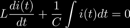

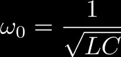
13 LC Tank KVL loop: Differentiate and rearrange: where is the resonant frequency 13


14 LC Tank Solution We want to solve The complementary solution is Initial conditions: Inductor current cannot change instantly 14
15 LC Tank Solution Can solve for the amplitude constant using 1 st derivative initial condition More importantly, we see that the natural response is a sinusoidal function Frequency determined by values of L and C Current, voltage, and energy simply slosh back and forth between the two devices! 15

16 Series RLC Circuit RLC Circuit Spring-Mass-Damper Voltage Current Capacitance Inductance Resistance Force Velocity Spring Mass Damper 16


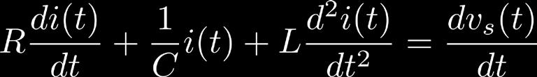
17 Series RLC Circuit KVL loop: Differentiate: Divide by L: 17


18 General Form of ODE RLC ODE: All ODEs can be written as follows: The particular solution / forced response depends on the form of forcing function 18


19 Homogeneous Equation The complementary solution is much more complex now! Depends on the following parameters: Damping coefficient Resonant frequency Damping ratio 19


20 Damping Coefficient Larger coefficient = more damping Mechanical analogue: friction Intuitively, resistance slows down current flow -> greater decay But inductance tries to keep current going 20

21 Damping Ratio The damping ratio tells us whether damping or oscillating dominates We get THREE (3!) different comp. solutions depending on its value Physically, does the current oscillate first, or does it just die out exponentially? 21
22 Overdamped Response Damping dominates; resistance is too (damn) high, preventing oscillations. Current decays at a rate determined by 22
23 Underdamped Response Damping is still present, but not strong enough to prevent oscillation Frequency of oscillation proportional to Overshoot Ringing 23
24 Critically Damped Response This response decays as fast as possible without causing any oscillations. Important for systems that need to settle down quickly without overshooting. 24
25 Summary Comparison of responses with different damping ratios Notice the tradeoff between initial overshoot and decay rate Source: Wikipedia, RLC Transient Plot.svg 25
26 Summary We will not be quantitatively solving for the comp. solutions for 2 nd -order ODEs. You should still be able to derive the ODEs. Understand qualitatively what s happening. Conclusion: These circuits are a b!tch to solve, especially with sinusoidal sources. Next time we ll approach this problem from an entirely different perspective. 26
EE 42/100 Lecture 18: RLC Circuits. Rev A 3/17/2010 (3:48 PM) Prof. Ali M. Niknejad
 Prof. Ali M. Niknejad") A. M. Niknejad University of California, Berkeley EE 100 / 42 Lecture 18 p. 1/19 EE 42/100 Lecture 18: RLC Circuits ELECTRONICS Rev A 3/17/2010 (3:48 PM) Prof. Ali M. Niknejad University of California,
A. M. Niknejad University of California, Berkeley EE 100 / 42 Lecture 18 p. 1/19 EE 42/100 Lecture 18: RLC Circuits ELECTRONICS Rev A 3/17/2010 (3:48 PM) Prof. Ali M. Niknejad University of California,
Experiment 1 LRC Transients
 Physics 263 Experiment 1 LRC Transients 1 Introduction In this experiment we will study the damped oscillations and other transient waveforms produced in a circuit containing an inductor, a capacitor,
An induced emf is the negative of a changing magnetic field. Similarly, a self-induced emf would be found by
 This is a study guide for Exam 4. You are expected to understand and be able to answer mathematical questions on the following topics. Chapter 32 Self-Induction and Induction While a battery creates an
[ á{tå TÄàt. Chapter Four. Time Domain Analysis of control system
 Chapter Four Time Domain Analysis of control system The time response of a control system consists of two parts: the transient response and the steady-state response. By transient response, we mean that
EECS40 RLC Lab guide
 EECS40 RLC Lab guide Introduction Second-Order Circuits Second order circuits have both inductor and capacitor components, which produce one or more resonant frequencies, ω0. In general, a differential
CHAPTER 7. Response of First-Order RL and RC Circuits
 CHAPTER 7 Response of First-Order RL and RC Circuits RL and RC Circuits RL (resistor inductor) and RC (resistor-capacitor) circuits. Figure 7.1 The two forms of the circuits for natural response. (a) RL
Chapter 8. Natural and Step Responses of RLC Circuits
 Chapter 8. Natural and Step Responses of RLC Circuits By: FARHAD FARADJI, Ph.D. Assistant Professor, Electrical Engineering, K.N. Toosi University of Technology http://wp.kntu.ac.ir/faradji/electriccircuits1.htm
Experiment 7: Undriven & Driven RLC Circuits
 MASSACHUSETTS INSTITUTE OF TECHNOLOGY Department of Physics 8.02 Spring 2006 OBJECTIVES Experiment 7: Undriven & Driven RLC Circuits 1. To explore the time dependent behavior of RLC Circuits, both driven
Lab 9 - AC Filters and Resonance
 Lab 9 AC Filters and Resonance L9-1 Name Date Partners Lab 9 - AC Filters and Resonance OBJECTIES To understand the design of capacitive and inductive filters. To understand resonance in circuits driven
The period is the time required for one complete oscillation of the function.
 Trigonometric Curves with Sines & Cosines + Envelopes Terminology: AMPLITUDE the maximum height of the curve For any periodic function, the amplitude is defined as M m /2 where M is the maximum value and
Numerical Oscillations in EMTP-Like Programs
 Session 19; Page 1/13 Spring 18 Numerical Oscillations in EMTP-Like Programs 1 Causes of Numerical Oscillations The Electromagnetic transients program and its variants all use the the trapezoidal rule
EXPERIMENT 8: LRC CIRCUITS
 EXPERIMENT 8: LRC CIRCUITS Equipment List S 1 BK Precision 4011 or 4011A 5 MHz Function Generator OS BK 2120B Dual Channel Oscilloscope V 1 BK 388B Multimeter L 1 Leeds & Northrup #1532 100 mh Inductor
Lab 5 Second Order Transient Response of Circuits
 Lab 5 Second Order Transient Response of Circuits Lab Performed on November 5, 2008 by Nicole Kato, Ryan Carmichael, and Ti Wu Report by Ryan Carmichael and Nicole Kato E11 Laboratory Report Submitted
LC Resonant Circuits Dr. Roger King June Introduction
 LC Resonant Circuits Dr. Roger King June 01 Introduction Second-order systems are important in a wide range of applications including transformerless impedance-matching networks, frequency-selective networks,
ECE212H1F University of Toronto 2017 EXPERIMENT #4 FIRST AND SECOND ORDER CIRCUITS ECE212H1F
 ECE212H1F University of Toronto 2017 EXPERIMENT #4 FIRST AND SECOND ORDER CIRCUITS ECE212H1F OBJECTIVES: To study the voltage-current relationship for a capacitor. To study the step responses of a series
Resonance in Circuits
 Resonance in Circuits Purpose: To map out the analogy between mechanical and electronic resonant systems To discover how relative phase depends on driving frequency To gain experience setting up circuits
Physics 132 Quiz # 23
 Name (please (please print) print) Physics 132 Quiz # 23 I. I. The The current in in an an ac ac circuit is is represented by by a phasor.the value of of the the current at at some time time t t is is
LINEAR CIRCUIT ANALYSIS (EED) U.E.T. TAXILA 07 ENGR. M. MANSOOR ASHRAF
 U.E.T. TAXILA 07 ENGR. M. MANSOOR ASHRAF") LINEAR CIRCUIT ANALYSIS (EED) U.E.T. TAXILA 07 ENGR. M. MANSOOR ASHRAF INTRODUCTION Applying Kirchhoff s laws to purely resistive circuits results in algebraic equations. While applying laws to RC and
LINEAR CIRCUIT ANALYSIS (EED) U.E.T. TAXILA 07 ENGR. M. MANSOOR ASHRAF INTRODUCTION Applying Kirchhoff s laws to purely resistive circuits results in algebraic equations. While applying laws to RC and
Today s topic: frequency response. Chapter 4
 Today s topic: frequency response Chapter 4 1 Small-signal analysis applies when transistors can be adequately characterized by their operating points and small linear changes about the points. The use
MAE106 Laboratory Exercises Lab # 5 - PD Control of DC motor position
 MAE106 Laboratory Exercises Lab # 5 - PD Control of DC motor position University of California, Irvine Department of Mechanical and Aerospace Engineering Goals Understand how to implement and tune a PD
Electric Circuit Fall 2017 Lab10. LABORATORY 10 RLC Circuits. Guide. Figure 1: Voltage and current in an AC circuit.
 LABORATORY 10 RLC Circuits Guide Introduction RLC circuit When an AC signal is input to a RLC circuit, voltage across each element varies as a function of time. The voltage will oscillate with a frequency
Class #7: Experiment L & C Circuits: Filters and Energy Revisited
 Class #7: Experiment L & C Circuits: Filters and Energy Revisited In this experiment you will revisit the voltage oscillations of a simple LC circuit. Then you will address circuits made by combining resistors
EE 42/100 Lecture 16: Inductance. Rev B 3/15/2010 (8:55 PM) Prof. Ali M. Niknejad
 Prof. Ali M. Niknejad") A. M. Niknejad University of California, Berkeley EE 100 / 42 Lecture 16 p. 1/23 EE 42/100 Lecture 16: Inductance ELECTRONICS Rev B 3/15/2010 (8:55 PM) Prof. Ali M. Niknejad University of California, Berkeley
A. M. Niknejad University of California, Berkeley EE 100 / 42 Lecture 16 p. 1/23 EE 42/100 Lecture 16: Inductance ELECTRONICS Rev B 3/15/2010 (8:55 PM) Prof. Ali M. Niknejad University of California, Berkeley
Simple Oscillators. OBJECTIVES To observe some general properties of oscillatory systems. To demonstrate the use of an RLC circuit as a filter.
 Simple Oscillators Some day the program director will attain the intelligent skill of the engineers who erected his towers and built the marvel he now so ineptly uses. Lee De Forest (1873-1961) OBJETIVES
Lab 9 AC FILTERS AND RESONANCE
 151 Name Date Partners ab 9 A FITES AND ESONANE OBJETIES OEIEW To understand the design of capacitive and inductive filters To understand resonance in circuits driven by A signals In a previous lab, you
#8A RLC Circuits: Free Oscillations
 #8A RL ircuits: Free Oscillations Goals In this lab we investigate the properties of a series RL circuit. Such circuits are interesting, not only for there widespread application in electrical devices,
Goals. Introduction. To understand the use of root mean square (rms) voltages and currents.
 voltages and currents.") Lab 10. AC Circuits Goals To show that AC voltages cannot generally be added without accounting for their phase relationships. That is, one must account for how they vary in time with respect to one another.
Lab 10. AC Circuits Goals To show that AC voltages cannot generally be added without accounting for their phase relationships. That is, one must account for how they vary in time with respect to one another.
Experiment 2: Transients and Oscillations in RLC Circuits
 Experiment 2: Transients and Oscillations in RLC Circuits Will Chemelewski Partner: Brian Enders TA: Nielsen See laboratory book #1 pages 5-7, data taken September 1, 2009 September 7, 2009 Abstract Transient
AC CURRENTS, VOLTAGES, FILTERS, and RESONANCE
 July 22, 2008 AC Currents, Voltages, Filters, Resonance 1 Name Date Partners AC CURRENTS, VOLTAGES, FILTERS, and RESONANCE V(volts) t(s) OBJECTIVES To understand the meanings of amplitude, frequency, phase,
Although shunt capacitors
 INSIDE PQ The Trouble With Capacitors Part 1 Switching capacitors seems like a simple proposition, but it can lead to some very interesting problems By R. Fehr, P.E., Engineering Consultant Although shunt
I. Introduction to Simple Circuits of Resistors
 2 Problem Set for Dr. Todd Huffman Michaelmas Term I. Introduction to Simple ircuits of esistors 1. For the following circuit calculate the currents through and voltage drops across all resistors. The
Study of Inductive and Capacitive Reactance and RLC Resonance
 Objective Study of Inductive and Capacitive Reactance and RLC Resonance To understand how the reactance of inductors and capacitors change with frequency, and how the two can cancel each other to leave
Goals. Introduction. To understand the use of root mean square (rms) voltages and currents.
 voltages and currents.") Lab 10. AC Circuits Goals To show that AC voltages cannot generally be added without accounting for their phase relationships. That is, one must account for how they vary in time with respect to one another.
Lab 10. AC Circuits Goals To show that AC voltages cannot generally be added without accounting for their phase relationships. That is, one must account for how they vary in time with respect to one another.
Physics for Scientists & Engineers 2 2 = 1 LC. Review ( ) Review (2) Review (3) e! Rt. cos "t + # ( ) q = q max. Spring Semester 2005 Lecture 30 U E
 Review (2) Review (3) e! Rt. cos t + # ( ) q = q max. Spring Semester 2005 Lecture 30 U E") Review hysics for Scientists & Engineers Spring Semester 005 Lecture 30! If we have a single loop RLC circuit, the charge in the circuit as a function of time is given by! Where q = q max e! Rt L cos "t
Review hysics for Scientists & Engineers Spring Semester 005 Lecture 30! If we have a single loop RLC circuit, the charge in the circuit as a function of time is given by! Where q = q max e! Rt L cos "t
Electronics and Instrumentation ENGR-4300 Spring 2004 Section Experiment 5 Introduction to AC Steady State
 Experiment 5 Introduction to C Steady State Purpose: This experiment addresses combinations of resistors, capacitors and inductors driven by sinusoidal voltage sources. In addition to the usual simulation
Lab 9 AC FILTERS AND RESONANCE
 09-1 Name Date Partners ab 9 A FITES AND ESONANE OBJETIES OEIEW To understand the design of capacitive and inductive filters To understand resonance in circuits driven by A signals In a previous lab, you
MASSACHUSETTS INSTITUTE OF TECHNOLOGY Department of Physics 8.02 Spring 2005 Experiment 10: LR and Undriven LRC Circuits
 MASSACHUSETTS INSTITUTE OF TECHNOLOGY Department of Physics 8.0 Spring 005 Experiment 10: LR and Undriven LRC Circuits OBJECTIVES 1. To determine the inductance L and internal resistance R L of a coil,
Inductance. Chapter 30. PowerPoint Lectures for University Physics, Thirteenth Edition Hugh D. Young and Roger A. Freedman. Lectures by Wayne Anderson
 Chapter 30 Inductance PowerPoint Lectures for University Physics, Thirteenth Edition Hugh D. Young and Roger A. Freedman Lectures by Wayne Anderson Goals for Chapter 30 To learn how current in one coil
LECTURE FOUR Time Domain Analysis Transient and Steady-State Response Analysis
 LECTURE FOUR Time Domain Analysis Transient and Steady-State Response Analysis 4.1 Transient Response and Steady-State Response The time response of a control system consists of two parts: the transient
Lecture Outline Chapter 24. Physics, 4 th Edition James S. Walker. Copyright 2010 Pearson Education, Inc.
 Lecture Outline Chapter 24 Physics, 4 th Edition James S. Walker Chapter 24 Alternating-Current Circuits Units of Chapter 24 Alternating Voltages and Currents Capacitors in AC Circuits RC Circuits Inductors
Modeling a RLC Circuits with Differential Equations
 Modeling a RLC Circuits with Differential Equations Teja Aluru and Aaron Osier May 16, 2014 Abstract This paper will explain basic concepts in the field of signal processing. We are going to create and
Department of Electrical & Computer Engineering Technology. EET 3086C Circuit Analysis Laboratory Experiments. Masood Ejaz
 Department of Electrical & Computer Engineering Technology EET 3086C Circuit Analysis Laboratory Experiments Masood Ejaz Experiment # 1 DC Measurements of a Resistive Circuit and Proof of Thevenin Theorem
Electronics and Instrumentation Name ENGR-4220 Fall 1999 Section Modeling the Cantilever Beam Supplemental Info for Project 1.
 Name ENGR-40 Fall 1999 Section Modeling the Cantilever Beam Supplemental Info for Project 1 The cantilever beam has a simple equation of motion. If we assume that the mass is located at the end of the
Lab 8 - INTRODUCTION TO AC CURRENTS AND VOLTAGES
 08-1 Name Date Partners ab 8 - INTRODUCTION TO AC CURRENTS AND VOTAGES OBJECTIVES To understand the meanings of amplitude, frequency, phase, reactance, and impedance in AC circuits. To observe the behavior
1. To study the influence of the gain on the transient response of a position servo. 2. To study the effect of velocity feedback.
 KING FAHD UNIVERSITY OF PETROLEUM & MINERALS Electrical Engineering Department EE 380 - Control Engineering Experiment # 6 Servo Motor Position Control Using a Proportional Controller OBJECTIVES: 1. To
BAKISS HIYANA BT ABU BAKAR JKE,POLISAS
 BAKISS HIYANA BT ABU BAKAR JKE,POLISAS 1 1. Explain AC circuit concept and their analysis using AC circuit law. 2. Apply the knowledge of AC circuit in solving problem related to AC electrical circuit.
Let's get going. As always, I will start with a review. And today we embark on another major milestone in our
 MITOCW L16-6002 OK. Good morning. Let's get going. As always, I will start with a review. And today we embark on another major milestone in our analysis of lumped circuits. And it is called the "Sinusoidal
EE155/255 F16 Midterm
 EE155/255 F16 Midterm Name: (please print) In recognition of and in the spirit of the Stanford University Honor Code, I certify that I will neither give nor receive unpermitted aid on this exam. Signature:
CHAPTER 6 INTRODUCTION TO SYSTEM IDENTIFICATION
 CHAPTER 6 INTRODUCTION TO SYSTEM IDENTIFICATION Broadly speaking, system identification is the art and science of using measurements obtained from a system to characterize the system. The characterization
Oscillations II: Damped and/or Driven Oscillations
 Oscillations II: Damped and/or Driven Oscillations Michael Fowler 3/4/9 Introducing Damping We ll assume the damping force is proportional to the velocity, and, of course, in the opposite direction. Then
Poles and Zeros of H(s), Analog Computers and Active Filters
, Analog Computers and Active Filters") Poles and Zeros of H(s), Analog Computers and Active Filters Physics116A, Draft10/28/09 D. Pellett LRC Filter Poles and Zeros Pole structure same for all three functions (two poles) HR has two poles and
Poles and Zeros of H(s), Analog Computers and Active Filters Physics116A, Draft10/28/09 D. Pellett LRC Filter Poles and Zeros Pole structure same for all three functions (two poles) HR has two poles and
Simple AC Circuits. Introduction
 Simple AC Circuits Introduction Each problem in this problem set involves the steady state response of a linear, time-invariant circuit to a single sinusoidal input. Such a response is known to be sinusoidal
EE301 ELECTRONIC CIRCUITS CHAPTER 2 : OSCILLATORS. Lecturer : Engr. Muhammad Muizz Bin Mohd Nawawi
 EE301 ELECTRONIC CIRCUITS CHAPTER 2 : OSCILLATORS Lecturer : Engr. Muhammad Muizz Bin Mohd Nawawi 2.1 INTRODUCTION An electronic circuit which is designed to generate a periodic waveform continuously at
10. Introduction and Chapter Objectives
 Real Analog - Circuits Chapter 0: Steady-state Sinusoidal Analysis 0. Introduction and Chapter Objectives We will now study dynamic systems which are subjected to sinusoidal forcing functions. Previously,
Oscillators. An oscillator may be described as a source of alternating voltage. It is different than amplifier.
 Oscillators An oscillator may be described as a source of alternating voltage. It is different than amplifier. An amplifier delivers an output signal whose waveform corresponds to the input signal but
UNIT I LINEAR WAVESHAPING
 UNIT I LINEAR WAVESHAPING. High pass, low pass RC circuits, their response for sinusoidal, step, pulse, square and ramp inputs. RC network as differentiator and integrator, attenuators, its applications
Electromagnetic Oscillations and Currents. March 23, 2014 Chapter 30 1
 Electromagnetic Oscillations and Currents March 23, 2014 Chapter 30 1 Driven LC Circuit! The voltage V can be thought of as the projection of the vertical axis of the phasor V m representing the time-varying
The Series RLC Circuit and Resonance
 Purpose Theory The Series RLC Circuit and Resonance a. To study the behavior of a series RLC circuit in an AC current. b. To measure the values of the L and C using the impedance method. c. To study the
DC and AC Circuits. Objective. Theory. 1. Direct Current (DC) R-C Circuit
 R-C Circuit") [International Campus Lab] Objective Determine the behavior of resistors, capacitors, and inductors in DC and AC circuits. Theory ----------------------------- Reference -------------------------- Young
[International Campus Lab] Objective Determine the behavior of resistors, capacitors, and inductors in DC and AC circuits. Theory ----------------------------- Reference -------------------------- Young
STUDY OF RC AND RL CIRCUITS Venue: Microelectronics Laboratory in E2 L2
 EXPERIMENT #1 STUDY OF RC AND RL CIRCUITS Venue: Microelectronics Laboratory in E2 L2 I. INTRODUCTION This laboratory is about verifying the transient behavior of RC and RL circuits. You need to revise
Positive Feedback and Oscillators
 Physics 3330 Experiment #5 Fall 2011 Positive Feedback and Oscillators Purpose In this experiment we will study how spontaneous oscillations may be caused by positive feedback. You will construct an active
6.776 High Speed Communication Circuits and Systems Lecture 14 Voltage Controlled Oscillators
 6.776 High Speed Communication Circuits and Systems Lecture 14 Voltage Controlled Oscillators Massachusetts Institute of Technology March 29, 2005 Copyright 2005 by Michael H. Perrott VCO Design for Narrowband
Figure 1: Closed Loop System
 SIGNAL GENERATORS 3. Introduction Signal sources have a variety of applications including checking stage gain, frequency response, and alignment in receivers and in a wide range of other electronics equipment.
Chapter 7. Response of First-Order RL and RC Circuits
 Chapter 7. Response of First-Order RL and RC Circuits By: FARHAD FARADJI, Ph.D. Assistant Professor, Electrical Engineering, K.N. Toosi University of Technology http://wp.kntu.ac.ir/faradji/electriccircuits1.htm
Worksheet for Exploration 31.1: Amplitude, Frequency and Phase Shift
 Worksheet for Exploration 31.1: Amplitude, Frequency and Phase Shift We characterize the voltage (or current) in AC circuits in terms of the amplitude, frequency (period) and phase. The sinusoidal voltage
AC Circuits. "Look for knowledge not in books but in things themselves." W. Gilbert ( )
") AC Circuits "Look for knowledge not in books but in things themselves." W. Gilbert (1540-1603) OBJECTIVES To study some circuit elements and a simple AC circuit. THEORY All useful circuits use varying
AC Circuits "Look for knowledge not in books but in things themselves." W. Gilbert (1540-1603) OBJECTIVES To study some circuit elements and a simple AC circuit. THEORY All useful circuits use varying
INTRODUCTION TO AC FILTERS AND RESONANCE
 AC Filters & Resonance 167 Name Date Partners INTRODUCTION TO AC FILTERS AND RESONANCE OBJECTIVES To understand the design of capacitive and inductive filters To understand resonance in circuits driven
Experiment 18: Driven RLC Circuit
 MASSACHUSETTS INSTITUTE OF TECHNOLOGY Department of Physics 8. Spring 3 Experiment 8: Driven LC Circuit OBJECTIVES To measure the resonance frequency and the quality factor of a driven LC circuit INTODUCTION
Lab 11. Speed Control of a D.C. motor. Motor Characterization
 Lab 11. Speed Control of a D.C. motor Motor Characterization Motor Speed Control Project 1. Generate PWM waveform 2. Amplify the waveform to drive the motor 3. Measure motor speed 4. Estimate motor parameters
Analog Circuits and Systems
 Analog Circuits and Systems Prof. K Radhakrishna Rao Lecture 31: Waveform Generation 1 Review Phase Locked Loop (self tuned filter) 2 nd order High Q low-pass output phase compared with the input 90 phase
Section 7 - Measurement of Transient Pressure Pulses
 Section 7 - Measurement of Transient Pressure Pulses Special problems are encountered in transient pressure pulse measurement, which place stringent requirements on the measuring system. Some of these
SWITCHED CAPACITOR VOLTAGE CONVERTERS
 SWITCHED CAPACITOR VOLTAGE CONVERTERS INTRODUCTION In the previous section, we saw how inductors can be used to transfer energy and perform voltage conversions. This section examines switched capacitor
RLC Circuits Building An AM Radio
 RLC Circuits Building An AM Radio (Left) An AM radio station antenna tower; (Right) A circuit that tunes for AM frequencies. You will build this circuit in lab to receive AM transmissions from towers such
System Inputs, Physical Modeling, and Time & Frequency Domains
 System Inputs, Physical Modeling, and Time & Frequency Domains There are three topics that require more discussion at this point of our study. They are: Classification of System Inputs, Physical Modeling,
First and second order systems. Part 1: First order systems: RC low pass filter and Thermopile. Goals: Department of Physics
 slide 1 Part 1: First order systems: RC low pass filter and Thermopile Goals: Understand the behavior and how to characterize first order measurement systems Learn how to operate: function generator, oscilloscope,
The Lumped-Element Switched Oscillator
 Circuit and Electromagnetic System Design Notes Note 55 May 008 The Lumped-Element Switched Oscillator Carl E. Baum University of New Mexico Department of Electrical and Computer Engineering Albuquerque
LABORATORY 4. Palomar College ENGR210 Spring 2017 ASSIGNED: 3/21/17
 LABORATORY 4 ASSIGNED: 3/21/17 OBJECTIVE: The purpose of this lab is to evaluate the transient and steady-state circuit response of first order and second order circuits. MINIMUM EQUIPMENT LIST: You will
Introduction. Transients in RLC Circuits
 Introduction In this experiment, we will study the behavior of simple electronic circuits whose response varies as a function of the driving frequency. One key feature of these circuits is that they exhibit
EE 442 Homework #3 Solutions (Spring 2016 Due February 13, 2017 ) Print out homework and do work on the printed pages.
 Print out homework and do work on the printed pages.") NAME Solutions EE 44 Homework #3 Solutions (Spring 06 Due February 3, 07 ) Print out homework and do work on the printed pages. Textbook: B. P. Lathi & Zhi Ding, Modern Digital and Analog Communication
NAME Solutions EE 44 Homework #3 Solutions (Spring 06 Due February 3, 07 ) Print out homework and do work on the printed pages. Textbook: B. P. Lathi & Zhi Ding, Modern Digital and Analog Communication
Antenna? What s That? Chet Thayer WA3I
 Antenna? What s That? Chet Thayer WA3I Space: The Final Frontier Empty Space (-Time) Four dimensional region that holds everything Is Permeable : It requires energy to set up a magnetic field within it.
Lab 4: Transmission Line
 1 Introduction Lab 4: Transmission Line In this experiment we will study the properties of a wave propagating in a periodic medium. Usually this takes the form of an array of masses and springs of the
Sirindhorn International Institute of Technology Thammasat University
 Sirindhorn International Institute of Technology Thammasat University School of Information, Computer and Communication Technology COURSE : ECS 34 Basic Electrical Engineering Lab INSTRUCTOR : Dr. Prapun
Basic Electronics Learning by doing Prof. T.S. Natarajan Department of Physics Indian Institute of Technology, Madras
 Basic Electronics Learning by doing Prof. T.S. Natarajan Department of Physics Indian Institute of Technology, Madras Lecture 26 Mathematical operations Hello everybody! In our series of lectures on basic
Power Electronics Single Phase Uncontrolled Half Wave Rectifiers. Dr. Firas Obeidat
 Power Electronics Single Phase Uncontrolled Half Wave Rectifiers Dr. Firas Obeidat 1 Table of contents 1 Resistive Load 2 R-L Load 3 R-L Load with Freewheeling Diode 4 Half Wave Rectifier with a Capacitor
Physics Jonathan Dowling. Lecture 35: MON 16 NOV Electrical Oscillations, LC Circuits, Alternating Current II
 hysics 2113 Jonathan Dowling Lecture 35: MON 16 NOV Electrical Oscillations, LC Circuits, Alternating Current II Damped LCR Oscillator Ideal LC circuit without resistance: oscillations go on forever; ω
LABORATORY 3: Transient circuits, RC, RL step responses, 2 nd Order Circuits
 LABORATORY 3: Transient circuits, RC, RL step responses, nd Order Circuits Note: If your partner is no longer in the class, please talk to the instructor. Material covered: RC circuits Integrators Differentiators
Exercise 1: Series RLC Circuits
 RLC Circuits AC 2 Fundamentals Exercise 1: Series RLC Circuits EXERCISE OBJECTIVE When you have completed this exercise, you will be able to analyze series RLC circuits by using calculations and measurements.
1. Consider the closed loop system shown in the figure below. Select the appropriate option to implement the system shown in dotted lines using
 1. Consider the closed loop system shown in the figure below. Select the appropriate option to implement the system shown in dotted lines using op-amps a. b. c. d. Solution: b) Explanation: The dotted
ω d = driving frequency, F m = amplitude of driving force, b = damping constant and ω = natural frequency of undamped, undriven oscillator.
 Physics 121H Fall 2015 Homework #14 16-November-2015 Due Date : 23-November-2015 Reading : Chapter 15 Note: Problems 7 & 8 are tutorials dealing with damped and driven oscillations, respectively. It may
Series Resistance Compensation
 Series Resistance Compensation 1. Patch clamping Patch clamping is a form of voltage clamping, a technique that uses a feedback circuit to set the membrane potential, V m, of a cell to a desired command
UNIT 2. Q.1) Describe the functioning of standard signal generator. Ans. Electronic Measurements & Instrumentation
 Describe the functioning of standard signal generator. Ans. Electronic Measurements & Instrumentation") UNIT 2 Q.1) Describe the functioning of standard signal generator Ans. STANDARD SIGNAL GENERATOR A standard signal generator produces known and controllable voltages. It is used as power source for the
UNIT 2 Q.1) Describe the functioning of standard signal generator Ans. STANDARD SIGNAL GENERATOR A standard signal generator produces known and controllable voltages. It is used as power source for the
3/23/2015. Chapter 11 Oscillations and Waves. Contents of Chapter 11. Contents of Chapter Simple Harmonic Motion Spring Oscillations
 Lecture PowerPoints Chapter 11 Physics: Principles with Applications, 7 th edition Giancoli Chapter 11 and Waves This work is protected by United States copyright laws and is provided solely for the use
Experiment Number 2. Revised: Fall 2018 PLECS RC, RL, and RLC Simulations
 Experiment Number 2 Revised: Fall 2018 PLECS RC, RL, and RLC Simulations Preface: Experiment number 2 will be held in CLC room 105, 106, or 107. Your TA will let you know Preliminary exercises are to be
MASSACHUSETTS INSTITUTE OF TECHNOLOGY Department of Physics 8.02 Spring Experiment 11: Driven RLC Circuit
 MASSACHUSETTS INSTITUTE OF TECHNOLOGY Department of Physics 8.2 Spring 24 Experiment 11: Driven LC Circuit OBJECTIVES 1. To measure the resonance frequency and the quality factor of a driven LC circuit.
The Discussion of this exercise covers the following points: Angular position control block diagram and fundamentals. Power amplifier 0.
 Exercise 6 Motor Shaft Angular Position Control EXERCISE OBJECTIVE When you have completed this exercise, you will be able to associate the pulses generated by a position sensing incremental encoder with
UNIT 1 CIRCUIT ANALYSIS 1 What is a graph of a network? When all the elements in a network is replaced by lines with circles or dots at both ends.
 UNIT 1 CIRCUIT ANALYSIS 1 What is a graph of a network? When all the elements in a network is replaced by lines with circles or dots at both ends. 2 What is tree of a network? It is an interconnected open
Experiment Number 2. Revised: Summer 2013 PLECS RC, RL, and RLC Simulations
 Preface: Experiment Number 2 Revised: Summer 2013 PLECS RC, RL, and RLC Simulations Preliminary exercises are to be done and submitted individually Laboratory simulation exercises are to be done individually
Experiment VI: The LRC Circuit and Resonance
 Experiment VI: The ircuit and esonance I. eferences Halliday, esnick and Krane, Physics, Vol., 4th Ed., hapters 38,39 Purcell, Electricity and Magnetism, hapter 7,8 II. Equipment Digital Oscilloscope Digital
Table of Contents Lesson One Lesson Two Lesson Three Lesson Four Lesson Five PREVIEW COPY
 Oscillators Table of Contents Lesson One Lesson Two Lesson Three Introduction to Oscillators...3 Flip-Flops...19 Logic Clocks...37 Lesson Four Filters and Waveforms...53 Lesson Five Troubleshooting Oscillators...69
EXPERIMENT NO. 4 EXPERIMENTS ON LADDER PROGRAMMING FOR MECHATRONICS SYSTEM
 EXPERIMENT NO. 4 EXPERIMENTS ON LADDER PROGRAMMING FOR MECHATRONICS SYSTEM DATE OF PERFORMANCE : INTRODUCTION: A Programmable Logic Controller, or PLC, is more or less a small computer with a built-in