User Manual For David GNSS Receiver
|
|
|
- Madeleine Lloyd
- 6 years ago
- Views:
Transcription


1 User Manual Version V User Manual For David GNSS Receiver 2018 Tersus GNSS Inc. All rights reserved. Sales & Technical Support: & More details, please visit
2 Table of Content 1. Overview Introduction Receiver Features Devices in David Package Rove Kit Mobile Mode David Receiver GNSS Antenna The 2pin-USB Power Cable COMM1-bluetooth Module Bracket for Rover GNSS Antenna Connector COMM2-7pin-USB & DB9 Data Cable Other accessories Rover Kit with 1W Radio Station W/915MHz Radio Rover Kit with 2W Radio Station W/460MHz Radio COMM2-7pin-USB & 5pin Cable Base Kit Mobile Mode Bracket for Base Tape Meter Base Kit with 1W Radio Station Base Kit with 2W Radio Station Base Kit with 30W Radio Station W Radio Other cables General operation Install the GNSS antenna Power on David Communication between Android phone and David / 74
3 3.3.1 With Wires With an External Bluetooth FW Upgrade & Auth code Firmware Updates Auth Code Download Files from Internal emmc Card Introduction of Nuwa Specification David Receiver ANTENNA AX3702 (HG) W Radio RS900C W Radio RS400L W Radio RS400L Typical operating David as a Rover to receive corrections from Internet David as a Base to transmit corrections to Internet Radios Transmit RTK Corrections between Two Davids Data Collection for Post Processing Terminology / 74
4 List of Figures Figure 1 Outlook of David GNSS receiver... 7 Figure 2 David in the box... 9 Figure 3 Field photo Figure 4 Field photo Figure 5 David Receiver Figure 6 AX3702(HG) antenna Figure 7 RF cable Figure 8 2pin-USB Power Cable Figure 9 Bluetooth Module Figure 10 Bracket for Rover Figure 11 GNSS Antenna Connector Figure 12 COMM2-7pin-USB & DB9 Data Cable Figure 13 USB Type A Male to DB9 Male cable Figure 14 USB Type A Male to USB Type A Male cable Figure 15 USB Type A Female to USB (Micro + Type C) OTG cable Figure 16 Height Measure Accessory Figure 17 Battery Bank Figure 18 Field Photo Figure 19 Field Photo Figure 20 1W Radio Station Figure 21 Field Photo Figure 22 Field Photo Figure 23 2W /460MHz Radio Figure 24 COMM2-7pin-USB & 5pin Cable Figure 25 Field Photo Figure 26 Bracket for Base Figure 27 Tape Meter Figure 28 Field Photo Figure 29 Field Photo Figure 30 Field Photo Figure 31 Metal Plate for Radio Antenna Figure 32 30W Radio Antenna Figure 33 Telescopic pole for Radio Antenna Figure 34 Field Photo Figure 35 Field Photo Figure 36 30W Radio Station Figure 37 Power cable for 30W radio Figure 38 COMM cable for 30W radio Figure 39 David GNSS receiver installation hook Figure 40 Schematic of Android phone to David with Wire Figure 41 Schematic of Android phone to David with Bluetooth Figure 42 Schematic of David connected to a Computer Figure 43 Download file from emmc card / 74
5 Figure 44 Booting up page Figure 45 Four Main Windows of Nuwa Figure 46 Panel of David Figure 47 Pin Definition of the three ports Figure 48 Schematic of Android phone to David with Wire Figure 49 Schematic of Android phone to David with Wire Figure 50 Schematic of Base/Rover with Radios Figure 51 Schematic of Static Data Collection / 74
6 List of Tables Table 1 The document / software used in this user manual... 6 Table 2 Seven David Variants... 9 Table 3 Devices in rover mobile mode Table 4 Definition of LEDs Table 5 Functions of COMM2-7pin-USB & DB9 Data Cable Table 6 Rover Kit with 1W Radio Station Table 7 LED Definition Table 8 Rover Kit with 2W Radio Station Table 9 Button Manual Table 10 LED Definition Table 11 Base Kit Mobile Mode Table 12 Base Kit with 1W Radio Station Table 13 Base Kit with 2W Radio Station Table 14 Base Kit with 30W Radio Station Table 15 The Definition of the Control Buttons Table 16 Definition of LEDs Table 17 Detailed steps Table 18 Detailed steps Table 19 Preparation for FW update Table 20 Detailed Steps for FW update Table 21 Detailed Steps to download files from emmc card Table 22 David GNSS Performance Table 23 Pin Definition Table 24 Antenna AX3702 (HG) Table 25 Specification for RS900C Table 26 Specification for RS400L Table 27 RS400L30 Radio Specification Table 28 Detailed steps for rover receive corrections from Internet Table 29 Detailed steps for Base transmit corrections to Internet Table 30 Detailed steps for David with Radios Table 31 Detailed Steps for Static Data Collection Table 32 List of terminology / 74
7 Notices The following notices apply to DAVID receiver. Changes or modifications to this equipment not expressly approved by Tersus could void the user s authority to operate this equipment or even has risk to damage the DAVID. Conventions The following conventions are used in this manual:! Information that supplements or clarifies text. A caution that actions, operation or configuration may lead to incorrect or improper use of the hardware. NUWA is Tersus suvery app, four tabs (Project, Device, Survey and Tools) are provided in the Nuwa main window. So, in chapter 4, all the operations in the Survey software will start from these four tabs. In all the figures, a line with two arrows at the two sides means it s a cable. A line with one arrow gives the installation direction. Table 1 The document / software used in this user manual Name Description Link Log & Command document Tersus GNSS Center Nuwa A warning that actions, operation or configuration may result in regulatory noncompliance, safety issues or equipment damage. Tersus Geomatics Office Document giving all the loggings output from David and all the commands to David Graphical tool to communicate with David Survey application running in the Android platform Post processing tool for static data ges/documents ges/software Support If you have a problem and cannot find the information you need in the product documentation, request technical support using the Tersus website at or mail to support@tersus-gnss.com 6 / 74

8 1. Overview 1.1 Introduction Tersus DAVID is a cost-efficient, palm-sized GNSS receiver, mainly for the mass survey market, but also for UAV/AGV/Agriculture application. A survey App is working with David, which can communicated with an android platform such as a phone or tablet via USB cable or an external Bluetooth module. The David can work as a base or a rover, it can support real-time RTK positioning as well as saving data for PPK application. Up to 4GB on-board EMMC card makes it easy to save data for PPK. The RS-232 serial port, IP67 standard and the external Bluetooth module can remove most of the inconvenience for field workers. All the operating can be done in the App Nuwa except downloading raw measurement data file, which will be done with Tersus GNSS Center, see Table 1 and section 3.5 Download Files from Internal emmc Card for detail. Figure 1 Outlook of David GNSS receiver 1.2 Receiver Features Supports GPS L1/L2, BDS B1/B2 and GLONASS G1/G2. Support RTCM2.3/3.x, CMR, CMR+ corrections. 7 / 74
9 Easy to connect an external powerful radio for long range. Solution rate can be 5Hz. 20Hz raw measurements output for post processing. The accuracy of carrier phase can be 1mm. On-board 4GB emmc card for data collection Static post-processing for mm-level accuracy. Bluetooth module makes wireless connection. Input power range is 5-12V, connect to battery bank directly. IP67 for water & dust proof, work reliably in harsh condition The Lemo connectors support mis-installation avoidance. 8 / 74

10 2. Devices in David Package This chapter will give the detailed introduction about all the devices in the package. David has seven variants, which is convenient for customers to select per their application. Different accessories are included in each variant. Table 2 gives a brief description of the seven variants. For more about them, refer to section 2.1 to section 2.7. All the seven variants are shipped in a plastic box in Figure 2. Figure 2 David in the box Table 2 Seven David Variants David variants Description Rover Kit Mobile The David receiver will receive RTK corrections from a Mode NTRIP caster or a TCP server. Rover Kit with 1W The David receiver will receive RTK corrections from an Radio Station external 1W 915Mhz radios. Rover Kit with 2W The David receiver will receive RTK corrections from an Radio Station external 2W 460MHz radios. Base Kit Mobile The David receiver will output RTK corrections to a Mode NTRIP caster or a TCP server. Base Kit with 1W The David receiver will output RTK corrections to an Radio Station external 1W 915Mhz radio. 9 / 74
11 Base Kit with 2W Radio Station Base Kit with 30W Radio Station The David receiver will output RTK corrections to an external 2W 460MHz radio. The David receiver will output RTK corrections to an external 30W 460MHz radio.! Rover Kit Mobile Mode and Base Kit Mobile Mode can work independently. Rover Kit with 1W Radio Station must work with Base Kit with 1W Radio Station. Rover Kit with 2W Radio Station must work with Base Kit with 2W Radio Station or Base Kit with 30W Radio Station. 2.1 Rove Kit Mobile Mode In this variant, the David will be connected to an Android phone with Bluetooth module or with cables. Tersus Survey Nuwa App will run in the Android phone to receive RTK corrections from a NTRIP caster or a TCP server. Refer to chapter 0 for typical operation Figure 3 Field photo / 74

12 Figure 4 Field photo Table 3 Devices in rover mobile mode Devices Number Items in the field photo David GNSS receiver 1 5 GNSS antenna 1 1 GNSS antenna connector 1 Not in the field photo, refer to section for detail. GNSS antenna cable 1 3 2pin-USB power cable 1 8 COMM1-bluetooth module 1 6, refer to COMM2-7pin-USB & DB9 Data cable 1 Not in the field photo, refer to section USB Type A Male to USB Type A Not in the field photo, refer 1 Male cable to Figure 14 USB Type A Female to USB(Micro + Not in the field photo, refer 1 Type C) OTG cable to Figure 15 USB Type A Male to DB9 Male cable 1 Not in the field photo, refer to Figure 13 Ranging pole 1 2 Height measure accessory 1 Not in the field photo, See Figure 16. Bracket for rover 1 4, see section Battery bank 1 7, see Figure 17 and 3.2 Power on David 11 / 74

13 2.1.1 David Receiver David has four interfaces, see Figure 5 David Receiver. Antenna input COMM1 port COMM2 port DC port Figure 5 David Receiver David s DC is for power input, COMM1 port is for COM1 and CAN ports, and COMM2 port is for COM2 and USB ports, see chapter 5 for detail. Table 4 Definition of LEDs LED Description PWR Solid ON when the David is power on. PV Solid ON when the David is in RTK solution. Solid OFF when the David in other position type. Refer to Chapter 5 for the specification of David receiver and the detailed definition of COMM1, COMM2 and DC ports GNSS Antenna GNSS antenna is used to receive the RF signal from the satellites. AX3702 (HG) is provided in the package, which must be connected to the David with the RF cable in the package. 12 / 74


14 Figure 6 AX3702(HG) antenna If an antenna from other companies will be used, contact Tersus to get permission. Or the David may not work as it s expected. Figure 7 RF cable The 2pin-USB Power Cable The power cable is used to connect a battery bank to the DC port of David. 13 / 74


15 Figure 8 2pin-USB Power Cable COMM1-bluetooth Module This Bluetooth module will use the COM1 port of David. Figure 9 Bluetooth Module The Bluetooth can only be installed to the COMM2 port of David. The SSID for this Bluetooth module is BT420A-xxxxx, where xxxxx is the last 5 digits of the Bluetooth serial number. No password is needed to pair with it Bracket for Rover Bracket for rover is used to fix all the devices on the ranging pole, which bring much convenience to field staffs. 14 / 74


16 Figure 10 Bracket for Rover GNSS Antenna Connector The GNSS antenna connector is used to install the GNSS antenna to a tripod for static data collection. Figure 11 GNSS Antenna Connector COMM2-7pin-USB & DB9 Data Cable The COMM2-7pin-USB & DB9 Data Cable has three functions: 15 / 74
 to download file saved on the internal emmc card, refer to section 0; 3.")

17 Table 5 Functions of COMM2-7pin-USB & DB9 Data Cable 1. Connect to an external 1W radio module. 2. Connected to USB Type A Male to DB9 Male cable (see Figure 13) to download file saved on the internal emmc card, refer to section 0; 3. Connect to USB Type A Male to USB Type A Male cable (see Figure 14) and USB Type A Female to USB (Micro +Type C) OTG cable (see Figure 15) to connect the Android phone with David, refer to section Figure 12 COMM2-7pin-USB & DB9 Data Cable! The COMM2-7pin-USB cable can only be installed into the COMM2 port of David Other accessories USB Type A Male to DB9 Male cable, USB Type A Male to USB Type A Male cable, USB Type A Female to USB (Micro + Type C) OTG cable and Height Measure Accessory are included in this variant. Figure 13 USB Type A Male to DB9 Male cable The driver for the cable above can be downloaded 16 / 74
 OTG cable The height measure")


18 Figure 14 USB Type A Male to USB Type A Male cable Figure 15 USB Type A Female to USB (Micro + Type C) OTG cable The height measure accessory is used to determine the height of the antenna with higher accuracy. Figure 16 Height Measure Accessory A battery bank is used to power on the David, it s not included in the package, and has to be provided by the customers, see section 3.2 Power on David for more detail. 17 / 74

19 Figure 17 Battery Bank 2.2 Rover Kit with 1W Radio Station In this variant, the David will be connected to an external 1W radio to receive RTK corrections from a base. With an external Bluetooth or with cables, the David will be connected to an Android phone, which is running Tersus Survey Nuwa to configure the David.! Rover Kit with 1W Radio Station must work with Base Kit with 1W Radio Station.! Rover Kit with 1W Radio Station can support Rover mobile mode Figure 18 Field Photo / 74

20 Figure 19 Field Photo 2-2 Table 6 Rover Kit with 1W Radio Station Devices Number Items in the field photo David GNSS receiver 1 7 GNSS antenna 1 1 GNSS antenna connector 1 Not in the field photo, refer to section for detail. GNSS antenna cable 1 3 2pin-USB power cable 1 8 COMM1-Bluetooth module 1 10, refer to COMM2-7pin-USB & DB9 data cable 1 11, refer to section USB Type A Male to USB Type A Male Not in the field photo, refer 1 cable to Figure 14 USB Type A Female to USB(Micro + Not in the field photo, refer 1 Type C) OTG cable to Figure 15 USB Type A Male to DB9 Male cable 1 Not in the field photo, refer to Figure 13 1W/915MHz radio 1 5, refer to section W/915MHz radio antenna 1 4 Ranging pole 1 2 Height measure accessory 1 Not in the field photo, See Figure 16. Bracket for rover 1 6, see section Battery bank 1 9, see Figure 17 and 3.2 Power on David 19 / 74
21 W/915MHz Radio This radio can work at 915MHz frequency only, the output power of this radio is 1W and the typical range is 3km. Refer to chapter 5 for detail. LED Antenna Interface Data Interface Figure 20 1W Radio Station Table 7 LED Definition LED Description When power on, this LED will blink RED once and keep off. P-S If data are transmitting, this LED will blink RED. If data are receiving, this LED will blink GREEN. 2.3 Rover Kit with 2W Radio Station In this variant, the David will be connected to an external 2W radio to receive RTK corrections from a base. With an external Bluetooth or with cables, the David will be connected to an Android phone, which is running Tersus Survey Nuwa to configure the David.! Rover Kit with 2W Radio Station can work with Base Kit with 2W Radio Station or Base Kit with 30W Radio Station.! Rover Kit with 2W Radio Station can support Rover mobile mode. 20 / 74

22 1 2 3 Figure 21 Field Photo Figure 22 Field Photo / 74
23 Table 8 Rover Kit with 2W Radio Station David variants Number Items in field photo David GNSS receiver 1 7 GNSS antenna 1 1 GNSS antenna connector 1 Not in the field photo, refer to section for detail. GNSS antenna cable Pin-USB power cable 1 9 COMM1-bluetooth module 1 10, refer to COMM2-7pin-USB & DB9 Data cable 1 Not in the field photo, refer to section USB Type A Male to USB Type Not in the field photo, 1 A Male cable refer to Figure 14 USB Type A Female to USB(Micro + Type C) OTG cable USB Type A Male to DB9 Male cable COMM2-7pin-USB & 5pin cable (0.35m) 1 1 Not in the field photo, refer to Figure 15 Not in the field photo, refer to Figure 13 11, refer to W/460MHz radio 1 5 2W/460MHz radio antenna 1 4 Ranging pole 1 2 Height measure accessory 1 Not in the field photo, See Figure 16. Bracket for rover 1 6, see section Battery bank 1 8, see Figure 17 and 3.2 Power on David W/460MHz Radio This radio can work at 460MHz frequency, the output power of this radio is 2W and the typical range is 5km. Refer to chapter 5 for detail specification. 22 / 74

24 Antenna Interface Channel Button Power Button Protocol Button Current Channel T/R Current Power ON/OFF Current Protocol Figure 23 2W /460MHz Radio Data Interface Table 9 Button Manual Button Channel Button Power Button Protocol Button Description Press once, the current channel will be shown. Press again, the current channel will increase 1, 1~ 8 channels are for use. Press once to select the output power. Protocol button is pressed to switch the protocol between TT (TT450 protocol) & TS (Transparent protocol)! Two 2W radios must have the same protocols and the same channel frequency before they can communicate each other. 23 / 74

25 Table 10 LED Definition LED H/L T/R TT/TS ON Description The LED is RED if 2W output is selected, is GREEN 0.5W output is selected. Blink RED if data is transmitting. Blink GREEN if data is receiving. Show the protocol selected. Is solid on after the power is on COMM2-7pin-USB & 5pin Cable The COMM2-7pin-USB & 5pin Cable is used to connect the David to the 2W radio station & an Android phone, or connect the David to the 30W radio station & an Android phone. The cable s length can be 0.35m or 1m in different variants. Figure 24 COMM2-7pin-USB & 5pin Cable COMM2-7pin-USB & 5pin Cable can only be installed into the COMM2 port of David. 2.4 Base Kit Mobile Mode In this variant, the David, working as a base, will transmit RTK corrections to a NTRIP caster or a TCP sever. The David will be connected to an Android phone with an external Bluetooth or with cables. Tersus Survey Nuwa is running in the Android phone to configure the David.! Base Kit Mobile Mode can work independently or work with Rover Kit Mobile Mode. 24 / 74

26 Figure 25 Field Photo 4! The tripod, the battery bank and the tribrach are not included in the package. Table 11 Base Kit Mobile Mode Devices Number Items in field photo David GNSS receiver 1 4 GNSS antenna 1 1 GNSS antenna connector 1 2 GNSS antenna cable Pin-USB power cable 1 6 COMM1-bluetooth module 1 8, refer to COMM2-7pin-USB & DB9 Data cable 1 Not in the field photo, refer to section USB Type A Male to USB Type A Not in the field photo, refer 1 Male cable to Figure 14 USB Type A Female to USB(Micro + Not in the field photo, refer 1 Type C) OTG cable to Figure 15 USB Type A Male to DB9 Male cable 1 Not in the field photo, refer to Figure 13 Tape meter 1 See Figure 27 Height measure accessory 1 Not in the field photo, See Figure / 74


27 Bracket for base , see Figure 17 and 3.2 Battery bank Power on David Bracket for Base This bracket is hooked on the tripod and all the devices in the field (an Android phone, a radio, a David and a battery bank) can be installed on it, which brings much convenience for field job. Figure 26 Bracket for Base Tape Meter Working with height measure accessory, the tape meter can give position of a point on ground with mm-level accuracy. Figure 27 Tape Meter 26 / 74

28 2.5 Base Kit with 1W Radio Station In this variant, the David, working as a base, will transmit RTK corrections to an external 1W radio. The David will be connected to an Android phone with cables or with the Bluetooth module. Tersus Survey Nuwa is running in the Android phone to configure the David.! Base Kit with 1W Radio Station can work with Rover Kit with 1W Radio Station only.! Base Kit with 1W Radio Station can support Base mobile mode Figure 28 Field Photo 5! The tripod, the tribrach and the battery bank are not included in the package. Table 12 Base Kit with 1W Radio Station Devices Number Items in field photo David GNSS receiver 1 5 GNSS antenna 1 1 GNSS antenna connector 1 9 GNSS antenna cable Pin-USB power cable 1 7 COMM1-bluetooth module 1 Not in the field photo, refer to 27 / 74
29 2.1.4 COMM2-7pin-USB & DB9 Data Cable 1 8 USB Type A Male to USB Type A Not in the field photo, refer to 1 Male cable Figure 14 USB Type A Female to USB(Micro + Not in the field photo, refer to 1 Type C) OTG cable Figure 15 USB Type A Male to DB9 Male cable 1 Not in the field photo, refer to Figure 13 1W/915MHz radio 1 4 1W/915MHz radio antenna 1 3 Tape meter 1 See Figure 27Figure 27 Tape Meter Height measure accessory 1 Not in the field photo, See Figure 16. Bracket for base 1 6 Battery bank 1 see Figure 17 and 3.2 Power on David 2.6 Base Kit with 2W Radio Station In this variant, the David, working as a base, will transmit RTK corrections to an external 2W radio. The David will be connected to an Android phone with cables or with the Bluetooth module. Tersus Survey Nuwa is running in the Android phone to configure the David.! Base Kit with 2W Radio Station can work with Rover Kit with 2W Radio Station only.! Base Kit with 2W Radio Station can support Base mobile mode. 28 / 74

30 Figure 29 Field Photo Figure 30 Field Photo 6-2 2! The tripod, the tribrach and the battery bank in Figure 29 and Figure 30 are not included in the package. Table 13 Base Kit with 2W Radio Station Devices Number Items in field photo David GNSS receiver 1 9 GNSS antenna 1 5 GNSS antenna connector 2 6 GNSS antenna cable / 74


31 COMM1-bluetooth module 1 Not in the field photo, refer to Pin-USB power cable 1 10 COMM2-7pin-USB & DB9 Data Cable 1 Not in the field photo, refer to section USB Type A Male to USB Type A Male Not in the field photo, 1 cable refer to Figure 14 USB Type A Female to USB(Micro + Not in the field photo, 1 Type C) OTG cable refer to Figure 15 USB Type A Male to DB9 Male cable 1 Not in the field photo, refer to Figure 13 COMM2-7pin-USB & 5pin Cable (0.35m) 1 11, refer to Figure 24 2W/460MHz radio W radio antenna 1 1 Metal plate for radio antenna 1 3, see Figure 31 Telescopic pole for radio antenna 1 2 Tape meter 1 See Figure 27 Tape Meter Height measure accessory 1 Not in the field photo, See Figure 16. Bracket for base 1 12 Battery bank 1 13, see Figure 17 and 3.2 Power on David Figure 31 Metal Plate for Radio Antenna Figure 32 30W Radio Antenna 30 / 74

32 Figure 33 Telescopic pole for Radio Antenna 2.7 Base Kit with 30W Radio Station In this variant, the David, working as a base, will transmit RTK corrections to an external 30W radio. The David will be connected to an Android phone with cables or with the Bluetooth module. Tersus Survey Nuwa is running in the Android phone to configure the David.! Base Kit with 30W Radio Station can work with Rover Kit with 2W Radio Station only.! Base Kit with 30W Radio Station can support Base mobile mode Figure 34 Field Photo / 74

33 Figure 35 Field Photo ! The two tripods and the tribrach in Figure 34 and Figure 35 are not included in the package. Table 14 Base Kit with 30W Radio Station Devices Number Items in field photo David GNSS receiver 1 12 GNSS antenna 1 5 GNSS antenna cable 1 7 GNSS antenna connector 2 4 COMM1-bluetooth module 1 Not in the field photo, refer to COMM2-7pin-USB & DB9 Data Cable 1 Not in the field photo, refer to section USB Type A Male to USB Type A Male Not in the field photo, 1 cable refer to Figure 14. USB Type A Female to USB(Micro + Not in the field photo, 1 Type C) OTG cable refer to Figure 15 USB Type A Male to DB9 Male cable 1 Not in the field photo, refer to Figure 13. COMM2-7pin-USB & 5pin Cable (1m) 1 10, refer to Figure 24. Power cable for 30W radio 1 9, refer to Figure 37 COMM cable for 30W radio 1 11, refer to Figure 38 30W radio W radio antenna / 74

34 Metal plate for radio antenna 1 3, see Figure 31 Telescopic pole for radio antenna 1 2 Tape meter 1 Not in the field photo, See Figure 27 Tape Meter Height measure accessory 1 Not in the field photo, See Figure 16. David GNSS receiver installation hook 1 13, see Figure W Radio The 30W radio is used when a longer baseline is required. The typical range is 15km, see chapter 5 for detail specification. Figure 36 30W Radio Station Table 15 and Table 16 give the definition of the control buttons and the LED, respectively. Table 15 The Definition of the Control Buttons Buttons Function ON/OFF Press 3s to power on or power off the radio station. ARROW UP/DOWN To select the channel RF PWR Press 3s to select the RF output power 33 / 74

35 Table 16 Definition of LEDs LEDs Description Solid RED if the external power is normal. ON/OFF Blink RED if external power is out of the limits. TX/RX Blink RED if the radio is transmitting. Blink GREEN if the radio is receiving. Channel Show the current channel BAT CAP Show the battery left. Show the current RF output power: OFF: 30W RF PWR BLUE: 20W RED: 10W RED+BLUE: 5W Other cables Figure 37 Power cable for 30W radio 34 / 74


36 Figure 38 COMM cable for 30W radio Figure 39 David GNSS receiver installation hook 35 / 74
37 3. General operation The general operation of David is related to the Tersus Survey Nuwa software, which will be introduced in the software manual. This chapter only describes how to do the hardware connection. To make David work, the customer must provide qualified power to David (refer to chapter 5 for requirement), power to the 30W radio (if 30W radio is used, refer to chapter 5 for detail) and an Android phone to run Tersus Survey Nuwa software. David may be damaged if devices from other companies are used to replace the ones in the package. And the warranty may be void if that happen. 3.1 Install the GNSS antenna Connect the antenna to David with the RF cable. Please ensure the connectivity is reliable.! The ideal place for a GNSS antenna is a point without GNSS signals blockage from horizon to horizon. 3.2 Power on David The input voltage to David is 5 12 VDC. It s highly recommended to power on David with an USB port (5VDC and 2A or more current output) from a battery bank with the power cable in the package, or the David may not boot up successfully. If other power than a battery bank is used to power on David, the customer has to make a power cable themselves and take all the risks involved. The working time of David depends on the capacity of the battery bank. The following formula can be used to estimate the operating time (assume the 36 / 74
38 output voltage is 5V): If no radio or an external 30W radio is connected to the David: Time (hour) = capacity (ma.hour) *5 / (1000 * 3.2) If 1W radio is connected to the David: Time (hour) = capacity (ma.hour) *5 / (1000 * ( )) If 2W radio is connected to the David: Time (hour) = capacity (ma.hour) *5 / (1000 * ( )) 3.3 Communication between Android phone and David David can communicate with an Android phone with a wire or with Bluetooth With Wires Figure 40 Schematic of Android phone to David with Wire! Three cables are used to connect the COMM2 port of David to the USB 37 / 74
39 port of the Android phone. They are: COMM2-7pin-USB & DB9 Data Cable or COMM2-7pin-USB & 5pin cable. USB Type A Male to USB Type A Male cable USB Type A Female to USB (Micro + Type C) OTG cable! The Android phone will NOT be charged when it s connected to David with wires. Table 17 Detailed steps 1. Connect the David s COMM2 port to the USB port of the Android phone with cables. 2. Connect the antenna to David with the RF cable (optional). 3. Power on the David with a battery bank. 4. Run Nuwa, Device ->Device Connect 38 / 74
40 5. Connect Type USB 6. Press Connect Config to update accordingly. 7. Press Connect to enable the communication with the David. 39 / 74
41 3.3.2 With an External Bluetooth Figure 41 Schematic of Android phone to David with Bluetooth! All the seven variants can support connection with Bluetooth as well as with cables. Table 18 Detailed steps 1. Install the Bluetooth module to the David s COMM2 port. 2. Connect the antenna to David with the RF cable (optional). 3. Power on the David with a battery bank. 4. Run Nuwa, Device ->Device Connect 40 / 74


42 5. Connect Type Bluetooth 6. Connect Config -> Search. The SSID is BT420A-xxxxx. No password is needed to pair with it. 7. Press Connect to enable the communication with the David. 3.4 FW Upgrade & Auth code Figure 42 Schematic of David connected to a Computer 41 / 74

43 Table 19 Preparation for FW update Hardware Installation 1. Install the USB Type A Male to DB9 Male cable to a computer s USB port. The cable will be mapped to a serial port, check the port number in the Device Manager of the computer. 2. Install the COMM2-USB + DB9 cable to the COMM2 port of the David. 3. Power on the David with the computer s USB port or with an external battery bank. 4. Connect the two cables together. 5. Run Tersus GNSS Center, fill the parameters in the Config page, press OK to communicate with the David Firmware Updates If a new firmware update is released, it will be available on the Tersus web site Or you can get the updates from Tersus support. The FW version of David receiver can be updated in field. Connect the David with Tersus GNSS Center, and input LOG VERSION, the following information will be output: VERSION COM UNKNOWN < 1 42 / 74


44 < BX306 G2SB2G Sep :46: is the FW version. See VERSION in Tersus GNSS Log & Command Reference document for more detail about this log. Table 20 Detailed Steps for FW update Hardware Installation Follow Figure 42 and the detailed steps in Table 19 to create communication between a David receiver and Tersus GNSS Center. Software Configure 1. Press Stop button to stop the communication between the computer and the receiver. 2. Select Help -> About Tersus GNSS Center 3. Select Update Firmware button in the following page 43 / 74


45 4. Select the upgrade file, when a file is selected, the file will be shown in the Update File bar. PORT is the PC s serial port for the USB adapter is recommended for the baud rate. Press Next 5. The following figure shows the FW is upgrading 6. After the FW is upgraded successfully, The following show 44 / 74

46 7. Press OK and Finish buttons to close the FW update window. Power cycle the receiver. 8. After the board is booted, the FW version can be confirmed by connecting to the receiver and input LOG VERSION and check the FW version. After the FW is upgdated successfully, the receiver must be power off for 5 seconds and power on again, or the receiver will not work Auth Code An auth code is used to determine the features and valid time for David receiver. If the auth code is expired, the receiver will not work. And a license requirement is output from all the ports. Before you contact Tersus for new auth code, input: LOG VERSION LOG AUTHLIST to the David receiver, and send all the output info to Tersus support. If the auth code application is approved, you will get a txt file, in which AUTHCODE command with the code will be given, just copy all of them and input them to the David receiver. 45 / 74

47 3.5 Download Files from Internal emmc Card The files saved on David s internal emmc card can be copied to the computer via a serial port. Figure 43 Download file from emmc card Table 21 Detailed Steps to download files from emmc card Hardware Installation 1. Follow Figure 42 and steps 1-5 in Table 19 to create communication between a David receiver and Tersus GNSS Center. Software Configure 2. Communicate the receiver with Tersus GNSS Center, input: COM COM // Configure baud rate of COM1 to , assume COM1 is connected to the PC. 3. Stop communicate with the David, re-communicate with it with Input LOGFILE CLOSE //close data collection 5. Input UNLOGALL //Stop outputting all the loggings 6. Press Tools -> Downloadfile 46 / 74


48 7. Select the file to be downloaded, press Download button, the following window will be shown. 8. After the file is downloaded successfully, the follow info will be given in the console window. 47 / 74


49 9. Go to Config page -> Save Option tab to check where the file is saved. 10. You can use this page to delete the files in the internal emmc card.! The downloading rate is about 2M/min, the downloading time can be estimated based on it. 48 / 74

50 4. Introduction of Nuwa Nuwa is the Tersus survey app, which is running in the Android phone. All the configure commands for the David are input with Nuwa, and all the operation of David are done with Nuwa. Four tabs menus are provided in the main window. They are Project, Device, Survey and Tools. See the Nuwa user manual for detail. Figure 44 Booting up page! Tersus Survey Nuwa is supporting Android system; no IOS version is available now. 49 / 74


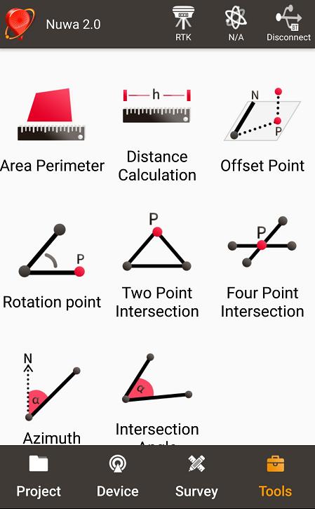
51 Figure 45 Four Main Windows of Nuwa 50 / 74
52 APPENDIX A 5. Specification 5.1 David Receiver Table 22 David GNSS Performance GNSS Performance Single positioning 1.5m RMS (Horizontal) 3.0m RMC (Vertical) Position Accuracy RTK Positioning 10mm+1ppm (Horizontal) 15mm+1ppm (Vertical) Static post processing 3mm+0.5ppm (Horizontal) 6mm+0.5ppm (Vertical) Time to First Fix Cold Start: <50s Warm Start: <30s Reacquisition 0.5 s L1 (typical) 1.0 s L2 (typical) Data Rate Measurements 20Hz Position 5Hz Time Accuracy 20ns RMS Velocity Accuracy 0.03m/s RMS C/A Code 10cm Measurement Precision P Code(zenith direction) 10cm Carrier Phase(zenith 1mm direction) Physical Description Size 104*65*31 mm 3 (David only) Weight 250g (David only) Mechanical Drawing 51 / 74
53 ENVIRONMENTAL Operating Temperature -40C to +85C Storage Temperature -55C to +95C Humidity MIL-STD-810G, Method Procedure II (95%) Random Vibration MIL-STD 810G Method 514.6, Category 24 (7.7 g RMS) Sinusoidal Vibration IEC (5 g) Bump ISO (25 g) Shock Operating: MIL-STD-810G, Method 516.6, Procedure I (40 g) Non-operating: MIL-STD-810G, Method 516.6, Procedure V (75 g) Water & dust proof IP67 Power Requirement Voltage VDC Power Consumption 3.2W without external Radio 6.2W with external 1W radio 9.8W with external 2W radio Figure 46 Panel of David 52 / 74
54 Table 23 Pin Definition Connector Pin COMM1 COMM2 DC No. LVTTL RS PWR PWR PWR 2 GND GND GND 3 TXD1 TXD2 4 RXD1 RXD2 5 GND GND 6 CAN_H/PPS 1 USB D+ 7 CAN_L/EVENT 1 USB D- Note 1: The default configure for pin6 and pin7 in COMM1 port are CAN_H and CAN_L. The two signals are multiplexed with PPS and EVENT. This feature is related to FW release, contact support@tersus-gnss.com for confirmation. Figure 47 Pin Definition of the three ports 53 / 74
55 5.2 ANTENNA AX3702 (HG) Table 24 Antenna AX3702 (HG) Antenna Specification Tracking signals GPS L1/L2/L5; BDS B1/B2/B3; GLONASS L1/L2 Impedance 50 Ohm Polarization RHCP Axial Ratio 3dB Azimuth Coverage 360 Output VSWR 2.0 Peak Gain 5.5dBi Phase Center Error ± 2mm LNA Specification LNA Gain 40±2dB Noise Figure 2.0dB VSWR 2.0 Input Voltage 3.3~12V DC Operating Current 45mA Ripple ± 2dB Differential transmission delay 5ns Physical Description Dimension Φ150*63.7mm Signal Connector TNC Female Installation connector 5/8 x 11 Environment Operating temperature -40C - +85C Storage temperature -55C - +85C Damp 45% - 95% Mechanical Drawing 54 / 74
56 5.3 1W Radio RS900C Table 25 Specification for RS900C General Specification Working Frequency 915MHz Data level RS-232 Data interface DB-9 male Size 78 * 51.5 * 26.4 mm 3 Operating Temperature Antenna impedance 50 Input voltage DC 3.3V 3.6V Power consumption 3.0W (transmitting) 180mW (receiving) Receiver Specification Sensitivity -123dBm(20kbps) Spurious response immunity 65dB Intermodulation immunity 60dB Stand by current 65mA saturation 90dB Distortion 5% Error rate 0.001% Transmission specification Modulation QPSK/BPSK Transmission power >1000mW Modulation distortion 3% Maximum frequency deviation 5KHz Transmission current 1000mA/DC3.3V Carrier frequency tolerance 5*10-6 Spurious frequency components -65dB Sleep current 5uA Working range >2km (@1Mbps) >5Km (@20Kbps) Mechanical Drawing s 55 / 74
57 56 / 74
58 5.4 2W Radio RS400L2 Table 26 Specification for RS400L2 Communication Interface Interface 9.6kbps in the air Lemo connector, RS-232 Voltage and Power Input voltage DC V Power consumption in transmitting 6.5W (DC5.5V, transmitting power 2W) 4W(DC5.5V, transmitting power 1W) 2.8W(DC5.5V, transmitting power 0.5W) 1.7W(DC5.5V, transmitting power 0.1W) Power consumption in <350mW (DC5.5V) receiving External Antenna Impedance 50 Ohm VSMR 1.5 Interface MCX female Modulation & Demodulation Modulation GMSK Data rate in air RF sensitivity Better than Code sensitivity -116 dbm BER Protocol PCC Transparent RF Specification Frequency range 10MHz (457MHz 467MHz) Channel width 25KHz Frequency ±1.5 ppm(25c) stability Channel number 116 (100 fixed channels, 16 configurable channels) Adjacent channel selectivity 60dB High power 33.5 Transmission 2 nd power dBm@DC5.5V power Middle power dBm@DC5.5V Low power dBm@DC5.5V Environment Temperature -30C - +60C (operating) -40C - +85C (storage) Mechanical 57 / 74
59 Size 107 * 62 * / 74
60 5.5 30W Radio RS400L30 Table 27 RS400L30 Radio Specification Communication Interface DTE-DCE Interface 9.6kbps in the air Serial port: RS-232, Band rate Interaction High (about 30W) PWR LED is OFF 2 nd high (about 20W) PWR LED is BLUE Power level Middle (about 10W) PWR LED RED Low (about 5W) PWR LED blink RED&BLUE Charging Alarm DC V B4 DC V Battery B3 DC V B2 DC V B1 DC V Power In/Out Input voltage DC V Power in transmitting (typical) Transmitting prohibition voltage Power in receiving (typical) Input Impedance 85W (DC 12.8V, 30W output) 65W (DC 12.8V, 20W output) 46W (DC 12.8V, 10W output) 33W (DC 12.8V, 5W output) DC V (default) DC V (configure range) <3W (Input voltage DC 12.8V) 50 Ohm VSWR 1.5 Interface Modulation Data rate in air RF sensitivity Decode sensitivity Protocol Frequency range Channel width Stability Antenna TNC female Modulation/Demodulation GMSK 9600bps@25KHz Better than 13dB@-119dBm -116 dbm BER 10E-5@9600bps Transparent EOT, SOUTH Radio MHz 25KHz 1.5ppm (25C) 59 / 74


61 Channel number Adjacent channel selectivity 116 (100 fixed channels, 16 configurable channels) 60dB Environment Temperature Operating C Dust proof and waterproof Size Weight Data port Power input port Installation Storage IP68 Physical Description C 165 * 74 * mm 3 with plastic protector About 1.75Kg LEMO EGA.0B.305 LEMO EGG.1B.302 Hook Mechanical Drawing Data Port Signal definition Pin 1: GND Pin 2: GND Pin 3: Output power Pin 4: RXD Pin 5: TXD 60 / 74

62 Pin 1: GND Pin2: PWR input Power input port 61 / 74
63 APPENDIX B 6. Typical operating The LEMO connectors in the David system support mis-installation avoidance. But it s highly recommended to double check the module/cable before they are installed to the correct ports. Mis-installation with force can damage the David.! The following may be used for David system: A battery bank for David An Android phone A power for 30W radio (if 30W radio is used) A tripod (optional). It s highly recommended that a David base variant is installed on a tripod. 6.1 David as a Rover to receive corrections from Internet! Section 3.6 and 3.7 give David and Android phone are connected with cables, refer to section for the connection with Bluetooth. 62 / 74
64 Figure 48 Schematic of Android phone to David with Wire! Three cables are used to connect the COMM2 port of David to the USB port of the Android phone. They are: COMM2-7pin-USB & DB9 Data Cable or COMM2-7pin-USB & 5pin cable. USB Type A Male to USB Type A Male cable USB Type A Female to USB (Micro + Type C) OTG cable Table 28 Detailed steps for rover receive corrections from Internet Hardware Installation 1. Install the GNSS antenna on a tripod or on a ranging pole at a point interested. 2. Connect the antenna to David with the RF cable. 3. Connect the David s COMM2 port to the USB port of the Android phone with cables. 4. Power on the David with a battery bank. Software Configure 5. Run Nuwa, Device ->Device Connect 63 / 74


65 6. Connect Type USB 7. Press Connect Config to update accordingly. 8. Press Connect to enable the communication with the David. 9. Go back to: Device -> Rover Station 10. Select PDA Network+Default Server1, then press Detail to configure 64 / 74
66 the parameters about the Network. 11. Select Network for Data Link 12. If Ntrip is selected for Protocol type, please input: IP, Port, Username, Password and Mount Point. 13. If TCP is selected for Protocol type, please input: IP and Port. 14. Go back to the Rover Station page and press Start 6.2 David as a Base to transmit corrections to Internet Figure 49 Schematic of Android phone to David with Wire! Three cables are used to connect the COMM2 port of David to the USB port of the Android phone. They are: COMM2-7pin-USB & DB9 Data Cable or COMM2-7pin-USB & 5pin cable. USB Type A Male to USB Type A Male cable USB Type A Female to USB (Micro + Type C) OTG cable! It s highly recommended that a base David is installed on a tripod. Table 29 Detailed steps for Base transmit corrections to Internet Hardware Installation 1. Install the tripod at a point interested. 2. Install a tribrach on the tripod, adjust it to horizontal level and install 65 / 74
67 the GNSS antenna and the antenna connector on it. 3. Connect the antenna to David with the RF cable. 4. Connect the David s COMM2 port to the USB port of the Android phone with cables. 5. Power on the David with a battery bank. Software Configure 6. Run Nuwa, Device ->Device Connect 7. Connect Type USB 8. Press Connect Config to update accordingly. 9. Press Connect to enable the communication with the David. 10. Go back to: Device -> Base Station 66 / 74


68 11. Select Auto Startup+PDA Network+Default Server1+Auto, then press Detail to configure the parameters about the Network. 12. If Auto Start is selected for Start Way, go to Step If Manual Start is selected for Start Way, input the base s position manually. 14. If Ntrip protocol is selected, please input: IP, Port, Username, Password and Mount Point. 15. If TCP is selected for Data Link, please input: IP and Port. 16. Go back to the Base Station page and press Start 6.3 Radios Transmit RTK Corrections between Two Davids! 1W base must work with 1W rover. 2W base must be work with 2W rover. 30W base must work with 2W rover. Only 30W base and 2W rover are given in this section since the other two configure are very simple. 67 / 74
69 BASE Rover Figure 50 Schematic of Base/Rover with Radios Table 30 Detailed steps for David with Radios Hardware Installation for the 30W Base 1. Install the two tripods at the points interested. 2. Install the 30W radio antenna with the telescopic pole for radio antenna. 3. Refer to Figure 29, install the metal plate, the GNSS antenna connector and the 30W radio antenna on one tripod. 4. Install a tribrach on the other tripod, adjust it to horizontal level and install the GNSS antenna and the antenna connector on it. 5. Connect the antenna to the base David with the RF cable. 6. Connect the David s COMM2 port to the USB port of the Android phone with cables. 7. Install the RF cable from the telescopic pole to the 30W radio station. 8. Connect the COMM cable to 30W radio, and to the base Daivd s DC port, respectively. Then connect it to the power cable for 30W radio. 9. Double check the cables above and connect the power cable to the external battery. Hardware Installation for the 2W Rover 10. Install a tripod at the point interested. 11. Install a tribrach on the tripod, adjust it to horizontal level and install the GNSS antenna and the antenna connector on it. 12. Connect the rover antenna to the rover David with the RF cable. 13. Install the COMM2-7pin-USB & 5pin cable to the COMM2 port of the rover David, and connect the other two connectors to the USB port of the Android phone with cables and to the 2W radio station, respectively. 14. Power on the David with an external battery bank. Software Configure for the 30W Base 15. Refer to to communicate the Android phone with the base David. 16. In Survey Nuwa, go to: Device -> Base Station 68 / 74

70 17. Select Auto Startup+Ex.Radio Auto, press Detail 18. If Auto Start is selected for Start Way, go to Step If Manual Start is selected in for Start Way, input the base s position manually. 20. Press OK to go back to the Base page, press Start. Software Configure for the 2W Rover 21. Refer to to communicate the Android phone with the rover David. 22. Go back to: Device -> Rover Station 69 / 74
 If the collection frequency increased, the")
71 23. Select Ext.Radio Auto, press Detail 24. Data Link is Radio and ensure the Band Rate is correct. 25. Go back to the rover page, and press Start. 6.4 Data Collection for Post Processing! The size of the logging: Collect raw measurements at 1Hz (about 110KByte/min if 20 satellites are tracked, about 165KByte/min if 30 satellites are tracked) If the collection frequency increased, the data size will be increased proportionately. David provides up to 4GB internal emmc card for data collection, before data collection, estimate whether the free space is enough for the data collection. Delete the file on emmc card with UNLINKFILE file_name to get more free space. Refer to Log & Command document for detail. 70 / 74
72 During data collection, a David must be installed on a tripod.! Rules for the file name & update time in the internal emmc card: 1) Name: file name is the xx..xx.dat, totally 8 digits, in which xxxx is the working time (seconds/100) of the David. For example, the David has worked 500 hours 40min, (500* *60)/100 = 18024, the file name will be dat. 2) Update time: if the David hasn t gotten the GNSS time, the update time of the files will be :0 (YYYYMMDD HH:MM). If the David has gotten the GNSS time, the update time will be the UTC time. Figure 51 Schematic of Static Data Collection Table 31 Detailed Steps for Static Data Collection Hardware Installation 1. Install a tripod at a point interested. 2. Install a tribrach on the tripod, adjust it to horizontal level and install the GNSS antenna and the antenna connector on it. 3. Connect the antenna to the David with the RF cable. 4. Create communication between the David and the Android phone with cables or with Bluetooth, refer to section and Software Configure 5. In Tersus Survey Nuwa, go to Survey, press Static Survey 71 / 74


73 6. Ensure the necessary parameters, including file name, data frequency and cutoff angle, etc. Press Start. 7. Follow steps 1-6 above to collect static data at other points interested. 72 / 74
74 7. Terminology Table 32 List of terminology Abbreviation Definition ASCII American Standard Code for Information Interchange CMR Compact Measurement Record DC Direct Current ESD Electro Static Discharge ECEF Earth Center Earth Fixed GLONASS GLObal NAvigation Satellite System GNSS Global Navigation Satellite System GPS Global Positioning System IF Intermediate Frequency IMU Inertial Measurement Unit IO Input/Output LED Light Emitting Diode LNA Low Noise Amplifier MPU Micro Processing Unit NMEA National Marine Electronics Association PC Personal Computer PPS Pulse Per Second RF Radio Frequency RINEX Receiver Independent Exchange format RMS Root Mean Squares RTK Real-Time Kinematic RTCM Radio Technical Commission for Maritime Services SMA Sub-Miniature-A interface TTFF Time to First Fix TTL Transistor-Transistor Logic level UART Universal Asynchronous Receiver/Transmitter USB Universal Serial BUS WGS84 Word Geodetic System / 74
User Manual For David GNSS Receiver
 User Manual Version V1.0-20180702 User Manual For David GNSS Receiver 2018 Tersus GNSS Inc. All rights reserved. Sales & Technical Support: sales@tersus-gnss.com & support@tersus-gnss.com More details,
Sales & Technical Support: &
 Sales & Technical Support: sales@tersus-gnss.com & support@tersus-gnss.com Table of Content Table of Content...1 List of Figures...3 List of Tables... 4 Revision History... 5 1. Introduction...6 1.1 Overview...6
User Manual. User Manual. Precis-BX316R. User Manual Tersus GNSS Inc. All rights reserved.
 User Manual Version V1.0-20170623 User Manual User Manual Precis-BX316R 2017 Tersus GNSS Inc. All rights reserved. Sales & Technical Support: sales@tersus-gnss.com & support@tersus-gnss.com More details,
User Manual. User Manual For BX Series GNSS Receiver
 User Manual Version V2.1-20190419 User Manual User Manual For BX Series GNSS Receiver 2019 Tersus GNSS Inc. All rights reserved. Sales & Technical Support: sales@tersus-gnss.com & support@tersus-gnss.com
David GNSS Receiver Base & Rover Kits
 A ffordable Centimeter Precision for Everyone Base & Rover Kits METER Tersus The Tersus is a cost-efficient, palm-sized GNSS receiver designed for UAVs, AGVs, and surveying applica ons. Using an external
For BX316/BX316R/BX316D Receivers
 User Manual Version V1.0-20171106 User Manual User Manual For BX316/BX316R/BX316D Receivers 2017 Tersus GNSS Inc. All rights reserved. Sales & Technical Support: sales@tersus-gnss.com & support@tersus-gnss.com
For BX316/BX316R Receivers
 User Manual Version V1.0-20171106 User Manual User Manual For BX316/BX316R Receivers 2017 Tersus GNSS Inc. All rights reserved. Sales & Technical Support: sales@tersus-gnss.com & support@tersus-gnss.com
User Manual For BX Series GNSS Receiver
 User Manual Version V1.0-20180629 User Manual User Manual For BX Series GNSS Receiver 2018 Tersus GNSS Inc. All rights reserved. www.tersus-gnss.com Aug, 2016 Revision Description Date Owner 1 Issued for
User Manual BX306. User Manual Tersus GNSS Inc. All rights reserved.
 User Manual User Manual BX306 2017 Tersus GNSS Inc. All rights reserved. Sales & Technical Support: sales@tersus-gnss.com & support@tersus-gnss.com More details, please visit www.tersus-gnss.com www.tersus-gnss.com
----STAR S86 GPS Receiver. User Guide. SOUTH CO., Ltd.
 ----STAR S86 GPS Receiver User Guide SOUTH CO., Ltd. www.southsurveying.com Sales@SOUTHsurveying.com 2 CONTENTS Chapter 1 Introduction... 1 STAR S86 GPS - System Summary... 1 Technical Specification...
Quick Start. Precis-BX305. Precise GNSS RTK Board.
 Quick Start Precis-BX305 Precise GNSS RTK Board www.tersus-gnss.com December, 2016 Quick Start Guide of Precis-BX305 This quick start guide provides the basic information needed to set up and use Precis-BX305
GLOBALSAT GPS Engine Board
 GLOBALSAT GPS Engine Board Hardware Datasheet Product No : MT-332(SMA) Version 1.0 GlobalSat WorldCom Corporation 16F., No. 186, Jian-Yi Road, Chung-Ho City, Taipei Hsien 235, Taiwan Tel: 886-2-8226-3799
GNSS Antenna. David GNSS Receiver. WiFi. 12V DC Ntrip Modem. Ethernet SIM 2/3/4G. Tersus GeoBee. Cost-effective Solution for Ntrip Corrections
 GNSS Antenna SIM 2/3/ Cost-effective Solution for Corrections Cost-effective Solution for Corrections The is a dedicated and cost-effec ve solu on to transmit or receive corre ons. With Tersus Caster Service,
Quick Start. Tersus GNSS Center. Configuration Tools for Tersus GNSS RTK Systems.
 Quick Start Tersus GNSS Center Configuration Tools for Tersus GNSS RTK Systems www.tersus-gnss.com July, 2016 1. Quick Start Guide of Tersus GNSS Center This quick start guide provides the basic information
User Manual. For AG960-Base. User Manual Tersus GNSS Inc. All rights reserved.
 User Manual Version V1.0-20170823 User Manual For AG960-Base 2017 Tersus GNSS Inc. All rights reserved. Sales & Technical Support: sales@tersus-gnss.com & support@tersus-gnss.com More details, please visit
Contents. Chapter 1 Brief Introduction of K9 series Chapter 2 K9 series mainframe The appearance of mainframe Interface...
 Contents Chapter 1 Brief Introduction of K9 series... 1 Chapter 2 K9 series mainframe... 2 2.1 The appearance of mainframe... 2 2.2 Interface... 2 2.3 The installation of battery... 3 2.4 Guiding light
GPS Time and Frequency Reference Receiver
 $ GPS Time and Frequency Reference Receiver Symmetricom s 58540A GPS time and frequency reference receiver features: Eight-channel, parallel tracking GPS engine C/A Code, L1 Carrier GPS T-RAIM satellite
ALPHA RTK RECEIVER USER GUIDE
 ALPHA RECEIVER USER GUIDE Version 0.8 October 25, 2018 info@polaris-gnss.com https://www.polaris-gnss.com 1 Table of Contents 1. Overview... 3 1-1 Introduction... 3 1-2 Operation Guidelines... 3 1-3 Alpha
GLOBALSAT GPS Engine Board
 GLOBALSAT GPS Engine Board Hardware Data Sheet Product No : MT-5110C Version 1.1 GlobalSat WorldCom Corporation 16F., No. 186, Jian-Yi Road, Chung-Ho City, Taipei Hsien 235, Taiwan Tel: 886-2-8226-3799
SL800 GNSS RTK System User Manual
 SL800 GNSS RTK System User Manual User Manual Revision SatLab SL800 GNSS Receiver Revision Date Revision Number Description 1 st Nov 2017 1 SL800 User Manual (Release V1.0) 1 Table of Contents Introduction...
SA-320 Installation Guide SA-320. Installation Guide. Date: Mar, 2011 Version: 2.5. All Rights Reserved
 SA-320 Installation Guide Date: Mar, 2011 Version: 2.5 All Rights Reserved Page 1 TABLE OF CONTENTS 1. Product Overview......3 1.1 Main Features...3 1.2 Applications.....3 1.3 Package Content.....3 2.
GLOBALSAT GPS+BDS Engine Board
 GLOBALSAT GPS+BDS Engine Board Hardware Data Sheet Product No : MT-5365B Version 1.0 GlobalSat WorldCom Corporation 16F., No. 186, Jian-Yi Road, Chung-Ho City, Taipei Hsien 235, Taiwan Tel: 886-2-8226-3799
GLOBALSAT GPS Engine Board
 GLOBALSAT GPS Engine Board Hardware Data Sheet Product No : MT-5531 Version 0.1 Globalsat Technology Corporation 16F., No. 186, Jian-Yi Road, Chung-Ho City, Taipei Hsien 235, Taiwan Tel: 886-2-8226-3799
GETTING STARTED GUIDE X91GNSS
 GETTING STARTED GUIDE X91GNSS Copyright Copyright 2009-2011 CHC. 2010-Shanghai HuaCe Navigation Technology Ltd. All rights reserved. The CHC are trademark of Shanghai Huace Navigation Technology Limited.
GeoMax GNSS Zenith10 & Zenith20 Series
 GeoMax GNSS Zenith10 & Zenith20 Series GeoMax About Us At GeoMax we provide a com- group with strong market At GeoMax, we concentrate on prehensive portfolio of inte- positions within measurement providing
SLX-1 Multi-Application GNSS Receiver
 SLX-1 Multi-Application GNSS Receiver w w w.sa tla b g p s. c o m SLX-1 Multi-Application GNSS Receiver Designed for CORS Ready for Anything European Standards GPS GLONASS BEIDOU GALILEO SBAS QZSS Long
Specifications. Trimble BX982 Modular GNSS Heading Receiver
 Name Configuration Option Base and Rover interchangeability Rover position update rate Rover maximum range from base radio Rover operation within a VRS network Heading and Moving Base operation Factory
Specifications. Trimble SPS985L GNSS Smart Antenna
 Receiver Name Configuration Option Base and Rover interchangeability Rover position update rate Rover maximum range from base radio Rover operation within a VRS network Heading and Moving Base operation
G10 G10 G10 LAND SURVEYING RTK GNSS SYSTEM RTK GNSS SYSTEM RTK GNSS SYSTEM. GENEQ inc. GNSS RTK measurement technology revolution
 GENEQ inc. S C I E N T I F I C I N S T R U M E N T S LAND SURVEYING RTK GNSS SYSTEM RTK GNSS SYSTEM RTK GNSS SYSTEM G10 G10 G10 The new generation full function GNSS Receiver GNSS RTK measurement technology
Inertial Sensors. Ellipse 2 Series MINIATURE HIGH PERFORMANCE. Navigation, Motion & Heave Sensing IMU AHRS MRU INS VG
 Ellipse 2 Series MINIATURE HIGH PERFORMANCE Inertial Sensors IMU AHRS MRU INS VG ITAR Free 0.1 RMS Navigation, Motion & Heave Sensing ELLIPSE SERIES sets up new standard for miniature and cost-effective
The new geo-fennel. FGS 1 GNSS Receiver
 The new geo-fennel FGS 1 GNSS Receiver 1 FGS 1 Unique GPS Set for multipurpose applications The geo-fennel FGS 1 is a robust receiver designed for challenging environments integrated into a compact device
The new geo-fennel. FGS 1 GNSS Receiver
 The new geo-fennel FGS 1 GNSS Receiver 1 FGS 1 Unique GPS Set for multipurpose applications The geo-fennel FGS 1 is a robust receiver designed for challenging environments integrated into a compact device
GNSS POSITIONING SYSTEM USER MANUAL
 GNSS POSITIONING SYSTEM USER MANUAL 1 1. A BRIEF INTRODCTION RUIDE dedicates to offer the most advanced GNSS equipment to surveyors. RTK surveying technology, as a cutting-edged and efficient surveying
SA-320 Installation Guide SA-320. Installation Guide. Date: June, 2007 Version: 2.2. All Rights Reserved
 SA-320 Installation Guide Date: June, 2007 Version: 2.2 All Rights Reserved Page 1 TABLE OF CONTENTS 1. Product Overview......3 1.1 Main Features...3 1.2 Applications.....3 1.3 Package Content.....3 2.
Indian Institute of Technology Kanpur Department of Civil Engineering
 Indian Institute of Technology Kanpur Department of Civil Engineering Inquiry No- CE/JNM/2013-14/R-10 30 December, 2013 Subject: Quotation for supply of Integrated System/Smart System Reflectorless Robotic
EB-230. Ultimate TRANSYSTEM INC. EB-230 Data Sheet
 GPS Engine Board EB-230 Data Sheet EB-230 EB-230 is an ultra miniature 12 x 12 mm 2 GPS engine board. It provides superior navigation performance under dynamic conditions in areas with limited sky view
CHC i80 GNSS Receiver QuickTour with LandStar7. (PDA Network Mode)
") CHC i80 GNSS Receiver QuickTour with LandStar7 (PDA Network Mode) 1.Prerequisites Hardware: CHC i80 rover, Controller Kit, SIM card,lithium Battery, pole Software: LandStar7 2.Steps to set i80 working
CHC i80 GNSS Receiver QuickTour with LandStar7 (PDA Network Mode) 1.Prerequisites Hardware: CHC i80 rover, Controller Kit, SIM card,lithium Battery, pole Software: LandStar7 2.Steps to set i80 working
ONCORE ENGINEERING NOTE M12 Oncore
 ONCORE ENGINEERING NOTE M12 Oncore 1. Product Specifications 2. Basic Description 3. Mechanical 4. Environmental 5. Electrical 6. RF Characteristics of Receiver 7. RF Requirements for Antenna 8. Performance
The on board surveyor
 The on board surveyor A PPK solution for drone-mapping Introduction DROBIT is a high precision positioning system created for drone-based photogrammetry. Its working principle is differential correction
Safety Information. CHC M6 GNSS Receiver. Revision 1.0 October 2017
 Safety Information il CHC M6 GNSS Receiver Revision 1.0 October 2017 Copyright Copyright 2016-2017 CHC Shanghai Huace Navigation Technology Ltd. All rights reserved. The CHC are trademark of Shanghai Huace
Guide to GNSS Base stations
 Guide to GNSS Base stations Outline Introduction Example of a base station (TUMSAT) Preparation for setting up a base station Procedure for setting up a base station Examples at two other universities
Leica GRX1200+ Series High Performance GNSS Reference Receivers
 Leica GRX1200+ Series High Performance GNSS Reference Receivers Leica GRX1200+ Series For permanent reference stations The Leica GRX1200+ Series, part of Leica's future proof System 1200, is designed specifically
KRONOS C3 Receiver User Guide
 KRONOS C3 Receiver User Guide Copyright Copyright 2015-2016 HORIZON Survey Instruments Services Pte Ltd. All rights reserved. The KRONOS are trademark of Survey Instruments Services Pte Ltd. All other
TRIUMPH-LS. The Ultimate RTK Land Survey Machine
 The Ultimate RTK Land Survey Machine Introducing GUIDE data collection in the. Visual Stake-out, navigation, six parallel RTK engines, over 3,000 coordinate conversions, advanced CoGo features, rich attribute
For Nuwa App. User Manual. User Manual Tersus GNSS Inc. All rights reserved.
 User Manual Version V1.1-20181228 User Manual User Manual For Nuwa App 2018 Tersus GNSS Inc. All rights reserved. Sales & Technical Support: sales@tersus-gnss.com & support@tersus-gnss.com More details,
RACELOGIC Antenna and Mount Options
 Antenna Options Your choice of antenna is critical to the accuracy of measurement. Racelogic provide a number of different antenna options, depending upon the measurement system, the type of vehicle being
Ct-G551. Connectec. SiRF V GPS Module. Specifications Sheet V0.1. Features: Ct-G551 V0.1 Specification Sheet
 SiRF V GPS Module Ct-G551 Specifications Sheet V0.1 Features: SiRF StarV ultra low power chipset GPS, GLONASS, Galileo and SBAS reception for high GNSS availability and accuracy Compact module size for
maxon document number:
 maxon document number: 791272-04 1 Table of contents... 2 2 Table of figures... 3 3 Introduction... 4 4 How to use this guide... 4 5 Safety Instructions... 5 6 Performance Data... 6 6.1 Motor data... 6
Specifications. Trimble SPS985 GNSS Smart Antenna
 Receiver Name Configuration Option Base and Rover interchangeability Rover position update rate Rover maximum range from base radio Rover operation within a VRS network Heading and Moving Base operation
AgGPS RTK 450 MHz Mobile Base Station and Rover Unit: Setting Up
 6 August 2007 AgGPS RTK 450 MHz Mobile Base Station and Rover Unit: Setting Up This Support Note describes how to set up a Trimble AgGPS RTK 450 mobile base station and rover radio. Instructions apply
Specifications. Trimble SPS985L GNSS Smart Antenna
 Receiver Name Configuration Option Base and Rover interchangeability Rover position update rate Rover maximum range from base radio Rover operation within a VRS network Heading and Moving Base operation
Catalog
 - 1 - Catalog 1. Description...- 3-2. Features...- 3-3. Applications... - 3-4. Block Diagram...- 3-5. Electrical Characteristics... - 5-6. Operation... - 5 - Power on Reset... - 5 - Working mode... - 6
RTKWARE UBR1 Technical Datasheet. ver1.1 (29/04/2015)
") RTKWARE UBR1 Technical Datasheet ver1.1 (29/04/2015) Table of Contents Table of Contents... 2 Overview... 3 Key-Features... 3 Applications... 3 Functional diagrams... 4 Power Distribution... 4 Data...
RTKWARE UBR1 Technical Datasheet ver1.1 (29/04/2015) Table of Contents Table of Contents... 2 Overview... 3 Key-Features... 3 Applications... 3 Functional diagrams... 4 Power Distribution... 4 Data...
Leica GRX1200 Series High Performance GNSS Reference Receivers
 Leica GRX1200 Series High Performance GNSS Reference Receivers Leica GRX1200 Series For permanent reference stations The Leica GRX1200 Series, part of Leica s new System 1200, is designed specifically
EB-250/ EB-250L. Ultimate TRANSYSTEM INC. EB-250 Series Data Sheet
 GPS Engine Board EB-250/ EB-250L EB-250 Series Data Sheet EB-250 is an ultra miniature 13 x 15 mm 2 GPS engine board. It provides superior navigation performance under dynamic conditions in areas with
Inertial Sensors. Ellipse Series MINIATURE HIGH PERFORMANCE. Navigation, Motion & Heave Sensing IMU AHRS MRU INS VG
 Ellipse Series MINIATURE HIGH PERFORMANCE Inertial Sensors IMU AHRS MRU INS VG ITAR Free 0.1 RMS Navigation, Motion & Heave Sensing ELLIPSE SERIES sets up new standard for miniature and cost-effective
2W UHF MHz Radio Transceiver
 2W UHF410-470 MHz Radio Transceiver Specification Copyright Javad Navigation Systems, Inc. February, 2006 All contents in this document are copyrighted by JNS. All rights reserved. The information contained
NS HP & NS HP BD User s Guide
 NS HP & NS HP BD User s Guide Rev. 0.8 September 30, 2017 1 Table of Contents 1. INTRODUCTION... 3 2. FEATURES OF NS HP... 5 3. APPLICATIONS... 5 4. PIN OUT DESCRIPTION... 6 5. CHECK OUT BASIC GPS FUNCTIONALITY...
Smart Design Technology Co., Ltd.
 Mars700Mini-TMC GNS TC5000 TMC Module Smart Design Technology Co., Ltd. 20F-8, No.107, Sec 1,Jhongshan Rd. Sinjhuang City, Taipei County 242, Taiwan Phone: +886-2-8522-7628 Fax: +886-2-8522-7784 Contact:
CL4490 HARDWARE INTEGRATION GUIDE VERSION 1.0. FCC Notice.
 CL4490 HARDWARE INTEGRATION GUIDE VERSION 1.0 wireless.support@lairdtech.com FCC Notice WARNING: This device complies with Part 15 of the FCC Rules. Operation is subject to the following two conditions:
IFR 4000 Portable Nav/Comm Test Set
 IFR 4000 Portable Nav/Comm Test Set Product Specification Note: A 15 minute warm-up period is required for all specifications. RF SIGNAL GENERATOR Marker Beacon Channel 72.0 to 78.0 MHz in 25 khz steps
GPS SMART ANTENNA (GWG4287SX)
") GPS SMART ANTENNA (GWG4287SX) SiRFSTARIII /LPx Specifications are subject to change without notice KOREA ELECTRIC TERMINAL CO., LTD. All right reserved http://www.ket.com 1. Introduction 1.1 Over view
GPS SMART ANTENNA (GWG4287SX) SiRFSTARIII /LPx Specifications are subject to change without notice KOREA ELECTRIC TERMINAL CO., LTD. All right reserved http://www.ket.com 1. Introduction 1.1 Over view
E205 Long Range Wireless Modem V1.0 Data Sheet
 E205 Long Range Wireless Modem V1.0 Data Sheet The Long Range Wireless Modem E205 is a radio transmitter / receiver designed for transparent wireless data transmission over long distances. It operates
CL4790 HARDWARE INTEGRATION GUIDE VERSION 3.0. Americas: Europe: Hong Kong:
 CL4790 HARDWARE INTEGRATION GUIDE VERSION 3.0 Americas: +1-800-492-2320 FCC Notice WARNING: This device complies with Part 15 of the FCC Rules. Operation is subject to the following two conditions: (1)
Version: 1.1 Revision: Data: Revised by: 006
 S9 III Version: 1.1 Revision: Data: 05-12-2012 Revised by: 006 2 Contents Chapter I : A brief introduction of S9 III... 5 Chapter II: S9 III mainframe... 7 II.1 The outlook of mainframe...7 II.2 Interfaces...7
Specifications. Trimble SPS555H Heading Add-on Receiver
 Receiver Name Configuration Option Base and Rover interchangeability Rover position update rate Rover maximum range from base radio Rover operation within a VRS network Heading and Moving Base operation
N o r t h G r o u p L T D. User Manual GNSS RTK Receiver SmaRTK Series
 1 Copyright Copyright 2007-2013 North. 2007 North Group LTD. All rights reserved. North is trademark of North Group LTD. All other trademarks are the property of their respective owners, 2007. Trademarks
Catalog
 - 1 - Catalog 1. Overview... - 3-2. Feature...- 3-3. Application... - 3-4. Block Diagram... - 3-5. Electrical Characteristics...- 4-6. Operation...- 4-1) Power on Reset... - 4-2) Sleep mode...- 4-3) Working
1 What s in the shipping package?
 SST 900B 900 MHz RS 232/RS 485 Wireless Modem Quick Start Guide 1 What s in the shipping package? SST-900B Wireless Modem CA-0910 Quick Start CD 3dBi 900M Hz Antenna Guide 2 External switch introduction
Safety Information. Revision 1.1 November 2015
 Safety Information il CHC i80 GNSS Receiver Revision 1.1 November 2015 Copyright Copyright 2014-2015 CHC Shanghai HuaCe Navigation Technology Ltd. All rights reserved. The CHC are trademark of Shanghai
DATASHEET. X-band Transmitter
 DATASHEET X-band Transmitter 1 Change Log... 3 2 Acronyms List... 4 3 System Overview... 5 4 Features and Benefits... 6 5 RF Characteristics... 6 6 Connectors... 8 6.1 Location... 8 6.2 Pinout: H1 - Stack
GPS Application. Global Positioning System. We provide GPS module ODM / OEM service, any GPS receiver you want, we can provide customized services.
 GPS Application Global Positioning System We provide GPS module ODM / OEM service, any GPS receiver you want, we can provide customized services. www.win-tec.com.tw sales@win-tec.com.tw GNSS Receiver WGM-303
GPS/GNSS Receiver Module
 GPS/GNSS Receiver Module 1. Product Information 1.1 Product Name: YIC91612IEB9600 1.2 Product Description: YIC91612IEB9600 is a compact, high performance, and low power consumption GNSS engine board which
I-2533CS series User Manual
 I-2533CS series User Manual Version 1.0.0, Sep. 2013 Service and usage information for I 2533CS / I 2533CS 60 / I 2533CS A / I 2533CS B I-2533CS series CAN to Single Mode Fiber Bridge User Manual (version
Localizer provides signal generation over the Localizer band of to MHz with 90 Hz and 150 Hz tones, amplitude modulated
 The IFR 4000 verifies the operation and installation of ILS, VOR and Marker Beacon receivers and VHF/UHF AM/FM and HF AM/SSB transceivers. The IFR 4000, with its lightweight size (under 8 lbs.), long run
Leica Spider Infrastructure HW Solutions Introducing: Leica GR30 & GR50
 Leica Spider Infrastructure HW Solutions Introducing: Leica GR30 & GR50 Reliable solutions for today and tomorrow Leica Spider Integrated Solutions Introducing: Leica GR30 & GR50 Outline Introducing Leica
MN5020HS Smart GPS Antenna Module
 1 Description The Micro Modular Technologies MN5020HS Smart Global Positioning System (GPS) Antenna Module is a complete 20-channel receiver with an integrated 18 x 18 mm patch antenna. With this highly
CONDOR C1722 GPS RECEIVER MODULE technical notes
 CONDOR C1722 GPS RECEIVER MODULE TECHNICAL HIGHLIGHTS Receiver: GPS L1 frequency (1575.42 MHz), C/A code, 22-channel continuous tracking NMEA output and input: serial port, USB port On-board low noise
S O P H I S T I C A T E D A U T O M A T I O N
 S O P H I S T I C A T E D A U T O M A T I O N Introduction Cost-effective Radio modems to any serial communication application Low power models, different frequency ranges RS232 / / RS422 / 5V TTL interface
Catalogue
 - 1 - Catalogue 1. Description... - 3-2. Features... - 3-3. Applications...- 3-4. Block Diagram... - 3-5. Electrical Characteristics...- 4-6. Operation...- 5 - Power on Reset... - 5 - Working mode... -
UB370. SupportBDS/GPS/GLONASSSatellites,andcan. morereliableandaccuratepositioningresult. LatestTri-System&Tri-frequencyRTK Engine
 Brief Introduction UB370 BDS/GPS/GLONASS Tri-System Hepta-Frequency High Precision OEM Board UB370isBDS/GPS/GLONASSTri-systemHepta-FrequencyOEMBoarddeveloped byunicorebasedonitsmaturebeidoucompatiblemulti-systemgnsssoc.ub370
LEICA SR20 GPS RECEIVER USE AND DATA PROCESSING FOR TOPOGRAPHICAL SURVEYING IN ORDER TO REHABILITATE A COMMUNAL ROAD
 LEICA SR20 GPS RECEIVER USE AND DATA PROCESSING FOR TOPOGRAPHICAL SURVEYING IN ORDER TO REHABILITATE A COMMUNAL ROAD Miluț Marius, Călina Jenica, Croitoru Alin, Buzatu Claudiu, Iosif Gheorghe University
SPEEDBOX Technical Datasheet
 SPEEDBOX Technical Datasheet Race Technology Limited, 2008 Version 1.1 1. Introduction... 3 1.1. Product Overview... 3 1.2. Applications... 3 1.3. Standard Features... 3 2. Port / Connector details...
GAUSS High Power UHF Radio
 [] Table of contents Table of contents... 1 1. Introduction... 3 Features... 4 Block Diagram... 6 2. Pinouts... 7 3. Absolute Maximum Ratings... 9 4. General Recommended Operating Conditions... 10 5. RF
GPS-Aided INS Datasheet Rev. 3.0
 1 GPS-Aided INS The Inertial Labs Single and Dual Antenna GPS-Aided Inertial Navigation System INS is new generation of fully-integrated, combined GPS, GLONASS, GALILEO, QZSS, BEIDOU and L-Band navigation
CONDOR C1919 GPS RECEIVER MODULE technical notes GENERAL OVERVIEW
 CONDOR C1919 GPS RECEIVER MODULE TECHNICAL HIGHLIGHTS Receiver: GPS L1 frequency (17. MHz), C/A code, -channel continuous tracking NMEA output and input: serial port On-board low noise amplifier GENERAL
Inertial Sensors. Ellipse Series MINIATURE HIGH PERFORMANCE. Navigation, Motion & Heave Sensing IMU AHRS MRU INS VG
 Ellipse Series MINIATURE HIGH PERFORMANCE Inertial Sensors IMU AHRS MRU INS VG ITAR Free 0.2 RMS Navigation, Motion & Heave Sensing ELLIPSE SERIES sets up new standard for miniature and cost-effective
SV-MESH Mesh network series Catalogue
 Catalogue 1. Description... 3 2. Features... 3 3. Applications... 3 4. Block Diagram... 4 5. Electrical Characteristics... 5 6. Operation... 5 Power on Reset... 5 Working mode... 6 Router mode... 8 Setting
USER MANUAL FIELDBEE AND RTK BEE STATION FULL VERSION. WE PROVIDE ONLINE SUPPORT: VERSION 1.0.
 USER MANUAL FULL VERSION VERSION 1.0. FIELDBEE AND RTK BEE STATION WE PROVIDE ONLINE SUPPORT: support@efarmer.mobi info@efarmer.mobi CONTENTS TABLE OF CONTENTS INTRODUCTION... 3 3 WAYS OF USING FIELDBEE...
K Series GNSS Receiver Getting Started
 K Series GNSS Receiver Getting Started K Series GNSS Receiver Getting Started Hi-Target Surveying Instrument Co., Ltd All Rights Reserved K Series GNSS Receiver Getting Started Content 1. Introduction
EB-500/ EB-500L. Ultimate TRANSYSTEM INC. EB-500 Series Data Sheet
 GPS Engine Board EB-500/ EB-500L EB-500 Series Data Sheet EB-500 is an ultra miniature 13 x 15 mm2 GPS engine board. It provides superior navigation performance under dynamic conditions in areas with limited
GPS/GLONASS/SBAS RECEIVER. Datasheet
 GPS/GLONASS/SBAS RECEIVER NV08C-RTK GNSS Card Datasheet Version 1.0 NVS Technologies AG Letzaustrasse 2, 9462 Montlingen, Switzerland Tel +41 71 760 07 36 Fax +41 71 760 07 38 www.nvs-gnss.com NV08C-RTK
GPS-Aided INS Datasheet Rev. 2.7
 1 The Inertial Labs Single and Dual Antenna GPS-Aided Inertial Navigation System INS is new generation of fully-integrated, combined GPS, GLONASS, GALILEO, QZSS and BEIDOU navigation and highperformance
EM-401. GPS ENGINE BOARD with Active Antenna PRODUCT GUIDE. Globalsat Technology Corporation (Taiwan)
") EM-401 GPS ENGINE BOARD with Active Antenna PRODUCT GUIDE Globalsat Technology Corporation (Taiwan) www.globalsat.com.tw USGlobalSat, Inc. (USA) www.usglobalsat.com Page 1 of 1 EM-401 GPS BOARD with Active
EM-401 GPS ENGINE BOARD with Active Antenna PRODUCT GUIDE Globalsat Technology Corporation (Taiwan) www.globalsat.com.tw USGlobalSat, Inc. (USA) www.usglobalsat.com Page 1 of 1 EM-401 GPS BOARD with Active
G3P-R232. User Manual. Release. 2.06
 G3P-R232 User Manual Release. 2.06 1 INDEX 1. RELEASE HISTORY... 3 1.1. Release 1.01... 3 1.2. Release 2.01... 3 1.3. Release 2.02... 3 1.4. Release 2.03... 3 1.5. Release 2.04... 3 1.6. Release 2.05...
CONDOR C1216 GPS RECEIVER MODULE technical notes ZELIA INTEGRATES ANTENNA, GPS RECEIVER, RTC AND LNA
 CONDOR C1216 GPS RECEIVER MODULE technical notes Zelia GPS RECEIVER MODULE TECHNICAL HIGHLIGHTS Integrated antenna element, GPS receiver, real-time clock, and low noise amplifier Receiver: Trimble Condor
500S Smart Antenna Installation and Operation Manual. P/N Rev. A 09/17 E29808
 500S Smart Antenna Installation and Operation Manual P/N 016-0171-668 Rev. A 09/17 E29808 Copyright 2017 1 Disclaimer While every effort has been made to ensure the accuracy of this document, Raven Industries
MD-261 MD-261. Features. Applications. Block Diagram. GNSS (GPS and GLONASS) Disciplined Oscillator Module
 Disciplined Oscillator Module") MD-261 GNSS (GPS and GLONASS) Disciplined Oscillator Module MD-261 The MD-261 is a fully integrated GNSS disciplined oscillator module in a compact surface mount 25 x 20 mm package. The module has an embedded
MD-261 GNSS (GPS and GLONASS) Disciplined Oscillator Module MD-261 The MD-261 is a fully integrated GNSS disciplined oscillator module in a compact surface mount 25 x 20 mm package. The module has an embedded
PDL Base. Radio Modem User's Guide. Revision 0.2 (preliminary) May 1999 Copyright 1999 Pacific Crest Corporation Document M00522
 May 1999 Copyright 1999 Pacific Crest Corporation Document M00522") i PDL Base Radio Modem User's Guide Revision 0.2 (preliminary) May 1999 Copyright 1999 Pacific Crest Corporation Document M00522 Pacific Crest Corporation 990 Richard Avenue, Suite 110 Santa Clara, CA
i PDL Base Radio Modem User's Guide Revision 0.2 (preliminary) May 1999 Copyright 1999 Pacific Crest Corporation Document M00522 Pacific Crest Corporation 990 Richard Avenue, Suite 110 Santa Clara, CA