7,W MEW. 50 -KW. "BOTTLES "! -KDKA's New Xmitter. 20-INCH TELETUBE! "DEAD OR ALIVE!" MACHINE -GUN SPEAKER! FISHY PUBLIC ADDRESS
|
|
|
- Wilfred Sutton
- 6 years ago
- Views:
Transcription


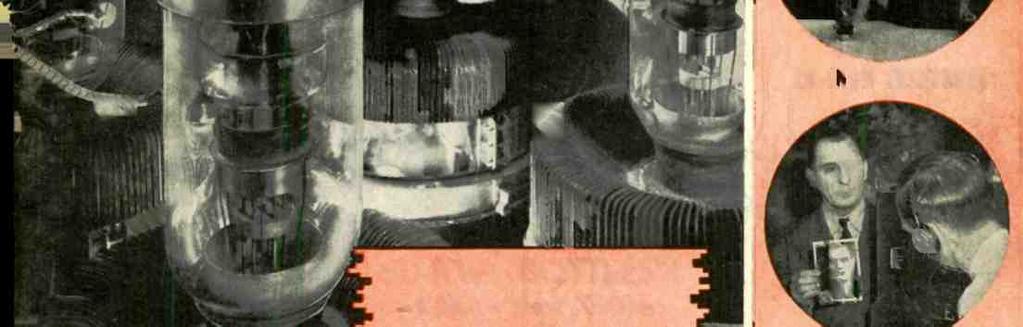
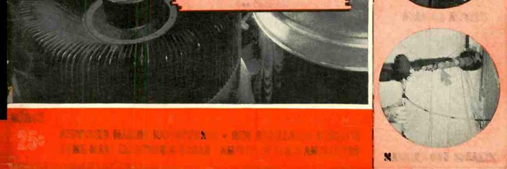


1 OVER 25 ILLUSTRATIONS FISHY PUBLIC ADDRESS 20-INCH TELETUBE! 50 -KW. "BOTTLES "! -KDKA's New Xmitter. See Page 527 "DEAD OR ALIVE!" -IN U. S. AND CANADA 7,W MEW SERVICING MARINE RADIOPHONES NEW OSCILLATOR CIRCUITS OME -MADE ELECTRONIC ORGAN AMPLIFIER TESTS AMPLIFIERS MACHINE -GUN SPEAKER!


2 o V / r F F rn S z Uw Z ca W A z q a 7 C CO N c 3 3 O o d,n Q W 0l ó; o o O z Z H. :49 O ^' oó_m<>= Z Z CÇ _ N- G Wÿ C arn O M p _M U Z Y U. `m J m C d vi memim u m UUU T oódeoo O W W á4o«^u=;c.z'. C~... C J ó G m._> o o Y a av oz i E-w o W CO E O - < < W CO. o U W 2 U 3 d W H W LC J W O. > _ -o < á E W N 3 á u p Oct}. - 6';i0 W V J Q ó`. ó - Ñ Z O J3 é a+ c f Vi W o 3 o P O ON I--g..=_. 4< mc J C o m a 0 O c 3 N ç w 4 O7 z J I o? W O ; o á m C a J 3U_ cvc _ zá yzv~f QW 3 4 U H ÿo<-3c'> O W ó O-o T< p 3 d a in:,w o m m o V O N c d. ú ai o+ ce Q o. a _ Q r d..`00.2 O m a W I o W W o v á z< W C E U U.c c' CJ C W a m N ta O < i_ W,.- F W O w h


3 RADIO -CRAFT for MARCH, Mr. J. E. SMITH, President National Radio Institute, Dept. OCX Washington, D. C. Dear Mr. Smith: Send me FREE, without obligation, your Sample Lesson and 64-page book, "Rich Rewards in Radio, which tells about Radio's spare time and full time opportunities and explains your method of training men at home to be Radio Technicians. (Write plainly) You Can Train at Home for Radio and Televi Clip the coupon and mail it. Tm so certain I can train you at home in your spare time to be a Radio Technician that I will send you a sample lesson free. Examine it, read it, see how clear and easy it is to understand. See how my course is planned to help you get a good job in Radio, a young, growing field with a future. You don't need to give up your present job, or spend a lot of money to become a Radio Technician. I train you at home in your spare time. Jobs Like These Go to Men Who Know Radio Radio broadcasting stations employ engineers, operators, technicians and pay well for trained men. Radio manufacturers employ testers, inspectors, foremen, servicemen in good -pay jobs with opportunities for advancement. Radio jobbers and dealers employ installation and servicemen. Many Radio Technicians open their own Radio sales and repair business and make $30, $40, $50 a week. Others hold their regular jobs and make $5 to $0 a week fixing Radios in spare time. Automobile, police, aviation, commercial Radio; loud- speaker systems, electronic devices, are newer fields offering good opportunities to qualified men. And my course includes Television, which promises to open many good jobs soon. Many Make $5 to $0 a Week Extra In Spare Time While Learning The clay you enroll, in addition to my regular course. I start sending you Extra Money Job Sheets which start showing you how to do actual Radio repair jobs. Throughout your course I send plans and directions which have helped many make $200 to $500 a year in Sampe Lesson FRE MY 'amide Icsson tex AtC Raddior e ltw R.P,batterY. trpnb ea in gr áes ro8ot You ç;;v:y eo lets a ñ u ie n sets,' seyrotoój o atece and recel era rrohne ch n ja devo b/ea a Ä ment, eck tend -ug to tra /izin balan tr alfgn- l'y raaiiingtatiee a ïyooeu he coupon. spare time tv ment; show circuits. This home interes than 0 Les and applica thoroughly ì St ecia/i2es rn Aviation Radio U a wftlt the Coens ehstgoal cialfz dio, Aviaripn tsars, ape noaro Mas vicecatooln hu50n ny mont g wso t kd v e Bd au j Le w Norwell-. Allda Antoni! 7isd" Yn Sah Name Address Age In e/ City tt, 4X-I ion earning. I send special Radio equip - how to conduct experiments. build 0 training method makes learning at fascinating, practical. I devote more exts exclusively to Television methods and cover Television fundamentals y Course. Also Give You This Proles Iona/ Servicing Instrument Here is the type of instrument Radio Technicians use-an All -Wave Set Servicing Instrument. It contains everything necessary to measure A.C. and D.C. voltages and current; to check resistances; adjust and align any set. old or new. It satisfies your needs for professional servicing after you graduate-can help you make extra money fixing sets while learning. Get Sample Lesson and 64.page Book Free -Mail Coupon Act today. Mail coupon now for Sample Lesson and 64- page book. They're FREE. They point out Radio's spare time and full time opportunities and those coming in Television ; tell about my course in Radio and Television : show many letters from men I trained, telling what they are doing and earning. Read my money back agreement. Find out what Radio offers you. Mail coupon in envelope or paste on penny postcard -NOW! J. E. SMITH, President Dept. OCX, National Radio Institute, Washington. D. C. at IYheR /reco /nrea eye A year ask.l. COepmpi d tier e made apare reed from raeto tame as 740/3 in setta the dl,pó ed m w rkwl. B osiey 2 Yegr Jincomé E ner n.. n St., te, pea 004. ou ; Nou.Ow,ns Orirer B "siness taking I omekrñ ki hh$25 w of wok out 4 ice shop to in mend Nmonth R ig ore g,, MohJ t 2047 moo, Calif. San T.ìya. Iwarollin nec,." E. lese then$ with kadry liteurai g R. G a L3;, d o Ttrrnin Poire/ g /n azebilde Please Say That You Saw It in RADIO -CRAFT
4 In th NEXT ISSUE HUGO GERNSBACK, Editor -in- Chief N. H. LESSEM THOS. D. PENTZ ROBERT EICHBERG Associate Editor Art Director Trade Digest Editor R. D. WASHBURNE, Managing Editor Contents MARCH, 940 VOLUME XI -- NUMBER 9 Issue 4 ow to Make a 2 Tube Mod Set Ultra_ Build an Flow g., Sup_ Sup- Flame p Generates Radio Emergency Utilities' tem Recording' Amplifier A playback Va. Playback of pb, VU, M, ThGmeand Sm News From Abroad 55 Editorial: Radio in 950 Hugo Gernsback 57 The Radio Month in Review 58 Building An Amplifier to Test Amplifiersl...Louis K. Sandor, W8QNU 520 Build Your Own Experimental Electronic Organ W. K. Allan 522 Marine Radio Telephone Installation and Servicing Richard Silberstein 524 How to Select and Place Sound Equipment -Part Ill- Placement of Equipment 526 The "New" KDKA 527 Public Address in Oceanarium 527 Converting a 5 -Inch Telly Kit for Receiving a 9 -Inch Image -Part II Charles Sicuranza 528 Sound Engineering -No. 3 Conducted by A. C. Shaney 53 New Circuits in Modern Radio Receivers -No F. L. Sprayberry 532 Servicing Puzzlers -No Recent Advances in Oscillator Circuits C. W. Palmer, E.E. 534 servicing "Orphans" and Private -Brand Sets -Part I Charles R. Leutz 536 A.F. Amplifier Load -Matching Technique A. C. Shaney 538 Servicing Questions and Answers 540 Case Histories of P.A. Sales -No. 6 (H. H. Keeshan) 540 The Beginners' All- Waver -Build This 2 -Tube Plug -in -Coil Breadboard Receiver M. N. Beitman 54 RADIO SERVICE DATA SHEETS: No Stewart- Warner Models 0I -5HI to 0I -5H9 (Chassis Model OI -5H) 542 No Zenith Model 6MF490 Auto -Radio (Ford Radio Model 9IA Roto -matit) New Tubes R. D. Washburne 544 Radio Trade Digest 545 Latest Radio Apparatus 558 "OUR COVER" The dedication last month of stetion KDKA in its new location at Allison Park, Pa., holds a special interest for many radio men. Although previous to 920 there had been sporadic transmissions of radio programs, consisting of voice, music. etc., it was not until this Westinghouse station broadcast the Harding -Cox election returns that scheduled broadcasting really took hold as a continuous service. Although KDKA has undergone numerous modifications it was only with its relocation at Allison Park that really extensive changes have been made. Some of the import of these changes and their effects upon the future of broadcasting may be gleaned by reference to the photograph of the 50,000 -W. power tubes illustrated on the cover and the other equipment shown and described on pg Published by Radcraft Publications, Inc. Publication office: 29 Worthington Street, Springfield, Mess. Editorial and Advertising Offices: 99 Hudson Street, New York City. Chicago Advertising Office: RADIO - CRAFT, 520 North Michigan Avenue, Chicago, Ill. RADIO -CRAFT is published monthly, on the first of the month preceding that of date; subscription price is $2.00 per year in U. S. and Canada. (In foreign countries, $2.50 a year to cover additional postage.) Entered at the post office at Springfield as second -class matter under the act of March 3, 879. Foreign Agents: London- Gorringe s American News Agency, 9A Green St., Leicester Square, W. C. 2, England. Paris -Messageries Dawson, 4 Rue Faubourg, Poissonniers, France. Melbourne- McGill's Agency. 79 Elizabeth St., Australie. Dunedin -tames Johnston, Ltd., New Zealand. * Text and illustrations of this magazine are copyright and must not be reproduced without permission of the copyright owners. Copyright 940 Radcraft Publications, Inc. 54


 does not mean 'Save Our Souls' or 'Save Our Ship' as is sometimes claimed, any more than the previous international distress call 'CQD' \"'SOS' (... - --. (-. -. -- - -.) meant 'Come Quick Danger.")
 call for sea emergency prior to the turn of the century, according to Federal Communications Commission records.")
5 RADIO -CRAFT for MARCH, 940 NEWS FROM ABROAD SSSS OR SOS? //MEWS dispatches from the war zone re- N report that 'SSSS' is rivaling 'SOS' as the marine radio operators call of distress. If this is fact, the former is not internationally recognized as is the 'SOS' signal in the International Morse Code," reported the Federal Communications Commission last month. The report is so informative, and so definitely clears -up a number of erroneous ideas, that it is here continued in its entirety. "In any event, the 'SSSS' (loes not officially mean 'Submarine Sighted' or any other particular words beginning with 'S.' The explanation is that the dot -dot -dot group, 4 times repeated (.....), representing these letters, has a characteristic swing and through common understanding and usage identifies the nature of the distress case..) does not mean 'Save Our Souls' or 'Save Our Ship' as is sometimes claimed, any more than the previous international distress call 'CQD' "'SOS' ( ( ) meant 'Come Quick Danger.' All such calls are based on the speed and clarity with which they can be transmitted. "There was no special wireless (or, as we now call it, radio) call for sea emergency prior to the turn of the century, according to Federal Communications Commission records. About that time the Marconi International Marine Communication Company, Ltd., began equipping ships for radiotelegraph communication. In doing so it adopted 'CQ' ( ), which had been in use in wire telegraph as a 'general call' for many years, as a precedence signal for any ship desiring to communicate with another ship or shore station. "The need for a common distress call was recognized at the preliminary International Radio Conference held at Berlin in 903. Here the Italian delegation suggested that in emergency a ship should send at intervals the signal 'SSSDDD.' No action was taken at this conference. "In 904 the British Marconi Company instructed its ship radio stations to substitute 'CD' for 'CQ.' Subsequently, the 'D' was inserted in the old 'CQ' call. At the 906 International Radio Conference at Berlin, however, 'SOS' was formally adopted. This combination was the - --.) which outgrowth of 'SOE' ( had been used by German ships but which was somewhat unsatisfactory because the final dot was easily obliterated by interference. "Even so, 'CQD' was so firmly established with some operators that its use was continued for some years thereafter. A notable example was its employment in summoning aid for the steamship Republic in 909. 'CQD' finally passed from the sea calls when the international radio conferences continued to approve 'SOS'." ABROAD ITALY seems to have stolen a march on the U.S. Fair interests (see Mr. H. Gemsback's editorial, "Radio at the Fair - Where?" in the Oct. 939 issue of "R.-C."!; also see Mr. Eichberg's editorial on pg. 49 ( "Radio Trade Digest" dept.] in the Jan. 940 issue). According to an issue of Radio E Televisione (Rome), received by Radio - Craft last month, the 942 World Fair at Rome will include a Radio Palace. The building will house the following shows: () An historical show of radio telegraphy and telephony; (2) An historical show of television; (3) A national show of the most recent developments of the Italian radio and television industry and technique; (4) Several studios where broadcasting and television programs will take place. Dominion radio received a swell build -up in England's House of Parliament last month when Sir James de Rothschild suggested that high -power transmitters be installed in the Dominions and Colonies "to spread our broadcast information still more widely over the world," according to The Lancet. Pointing out that there are hundredof millions of people in India, China and the rest of the Far East, including a 00,000,000 black and white, more in Africa and millions in the two Americas, it was stated that "the strategy of information must be on a world scale." Far -away India is not so remote that it has not constituted a market for American radio products. However this state of affairs may not long continue if the Bengal Board of Industrial Research succeeds in its plan to sell the Government of Bengal the idea of fabricating every radio component, "except, of course, the valve." "It has been decided with regret to suspend publication of The Marconi Review during the war," reads a release received last month from Marconi's Wireless Telegraph Co., Ltd., London, England, publishers of this interesting technical house -organ. "Dear Listener: Due to the delay in foreign mails at the present time, it has been impossible for us since October to send you our printed programs," reads a release from Reichs -Rundfunk G.m.b.H., Deutscher Kurz - wellensender (the German Short -Wave Station), received by Radio -Craft last month. Report, in continuing, suggests instead that American listeners tune -in the daily program previews at a stated time each (lay. A British Broadcasting Corp. overseas press bulletin reports that 6 private houses, "somewhere in England," comprise the group to which the B.B.C. evacuated 300 members of its staff and artists when war broke out, and where they will stay for the "duration." In one house the studio is a room, sandwiched between a shop and a roof -top machine -gun post, in which 75 members of the B.B.C. Symphony Orchestra rehearse and play for listeners daily. DOMESTIC TID -BITS ACCORDING to a newspaper columnist last month, Mayor LaGuardia is becoming quite chummy with the 2 -way shortwave radiophone in his car. The item points out that the Mayor's calls are routed through Fire Headquarters rather than Police Headquarters because a 2 -way system is utilized by the firemen for their boats. Since there is no speech- scrambling device in the fire -fighting radio system, this channel is virtually a party -wire for the Mayor's conversations. Seedlings of corn germinated in wet sand and exposed to strong doses of 2ig -meter radio waves for about % -hour, then replanted, resulted in dwarf growths, Science News Letter reported last month. Similar stunting effect has been noticed in the application of heat to germinating seedlings. Experiments were conducted at the California Institute of Technology. Please Say That You Saw It in RADIO -CRAFT I'll Prove That You Can Have a Good Job in Radio... or a Bus! - ness al YOUR OWN I offer you a new and altogether different type of practical Training for a money -making career in Radio and Television. No matter If you desire to BE YOUR OWN BOSS in your own business, or hold down a good Job in Radio. my Personalized Training will quickly give you the useful knowledge to win success. I make it EASY for >nu to get started. YOU LEARN RIGHT AT HOME in SPARE TIME... EARN from the START Too DO PRACTICAL EXPERI- MENTS with real Radio Equipment. with your own hands. Thus the principles of Radio become crystalclear to you. The valuable spare -tine BUSINESS BUILD- ERS I supply will show you how to put this knowledge to work in handling profitable In g. I GIVE YOU CLOSE PER. SONAL COACH. ING SERVICE sert learn NO PREVIOUS EX PERIENCE NEEDED r. make. I drcb,r,...,.,. what education I. La -en. o oing at the beginning of It,' covers tandable style all u Televisubjects ol e e Iar,u d t r R.Á0. n, ILn:,!r and m.. éio`lt. 55 You GET PROFES SIONAL TEST EQUIPMENT plus EXPERIMENTAL OUTFITS 46 RADIO PARTS RAD0 TOOLS All- Purpose Analyzer READ WHAT TH S STUDENT SAYS Earned $250, Since Starting Course Course have) only leted one third of the SDra berry and Á Il cary Interesting, which takes tt By devoting several hour. spare time dailto y study lag né servicing le have de shout 3250 gros stnre t aii,g the Course. Earl W. Hostetter. R. No. 4, Lchanun, l'a. SERVICEMEN I offer A.rv:n,co. rraln,nc nor Ìbeady in Radio. it Coot complete detail.. n my FREE 52.page Hook. REMEMBER - THE SPRAYBERRY COURSE IS SOLD UNDER A MONEYBACK AGREEMENT DON'T DELAY! ACT NOW! I SPRAYBERRY ACADEMY OF F. L. Sprayberry. Pros. RADIO 320 -C Unisenity Plage. N.W.. Washington, D. C. I Please send n e FREI: copy of "HOW TO MAEF. MONEY IN RAHIO. Name Age IAddress I City... Tear off State u. e tv'teeinlénchá e ee te ó.paste on I


6 56 RADIO-CRAFT for MARCH, 940 Tot ßtt S'Qtlfl'dfl9 - Tat iliffet Ptatiti- USE GERNSBACK MANUALS AND BOOKS! aakvicing WITH StTANALYZEM3 INCE 93 Servicemen have been buying more GERNSBACK OFFICIAL RADIO SERVICE MANUALS year after year. The authentic material, easily accessible diagrams and complete service data make them invaluable to dealers and radio Servicemen. Without a Gernsback Service Manual at the repair job, there's time and profit lost. Your service kit or laboratory is incomplete without all the GERNSBACK OFFICIAL RADIO SERVICE MANUALS. There are GERNSBACK MAN- UALS for servicing auto- radios, also refrigeration and air conditioning equipment. VOLUME T OFFICIAL RADIO SERVICE MANUAL Ortie I.00sseleafa('over. 5(reo00 DIU2 x Ì ctv Pat Welgnr Ì04y lb. 936 OFFICIAL RADIO SERVICE MANUAL Ova,00 Pages Over Illustrations Stiff, Leather. ties Looseleaf Covers Sise D a 2 Inches Nat Weight 8 lbs.. 7, OFFICIAL RADIO SERVICE MANUAL PoelfCo. Stn s signs sl lbs. $7.00 LaV ealllet Loeef ver ize 9x l Inches Net 935 OFFICIAL AUTO -RADIO SERVICE MANUAL tm LaoNPeaf Coverssv:rsi oe 9VITLIches. NettWeight iss.5 lbs $2, OFFICIAL RADIO SERVICE MANUAL Ova 400 Page veer Illustration. Flcxa,le.,.coiner. wwf Covers Sire a : z Inches Net weubt $3.50 VA. Ilia. 932 OFFICIAL RADIO SERVICE MANUAL Over.000 Page. Over Illustration, Flexible. Leatherette. Luoseleaf Covers. Sire u x 2 Inches Net Weight 4/2 Its. OFFICIAL REFRIGERATION SERVICE MANUAL (Volume II) Over 35 Pages Over 300 Illustration, Flexible. Leather. out., Looseleaf Covers. Sise 9 x Inches Net Weight,5 lbs. OFFICIAL AIR CONDITIONING SERVICE MANUAL nrer 352 Page, e aver 000 Illustrations Flexible, ther rite, Looeeleaf Covers. Sire D x 2 Inches Net weight 2i,. lbs. $5.00 Loa $5.00 To order these famous Manuals, see or write to your jobber or favorite mail order house. If more convenient, mail coupon directly to publishers. RAD[RAFT PUBLICATIONS, Inc. 99 HUDSOn STREET REW YORH, R. Y. Please Say That Many Ji/ w /ßooK #ave ßeen 9dded to RADIO -CRAFT LIBRARY SERIES Get into the swing of reading instructive, authoritative books on technical subjects- radio, air conditioning and refrigeration. It's the easiest, quickest and most inexpensive way to improve your knowledge on these topics. In This series, popularly known as the RADIO -CRAFT LIBRARY SERIES, are all the titles necessary to your personal advancement. Only by careful study of these enlightening books, can you gain adequate experience In fields of radio, air conditioning and refrigeration. Each book is uniform. The volumes measure 6 x 9 inches -contain 64 pages, and have stiff, flexible covers. PRICE 50c PER BOOK. All books are sent to you postpaid. Here Are The Titles: Book No. 2 MODERN VACUUM TUBES Book No. S BRINGING ELECTRIC SETS UP -TO -DATE Book No. 3 ABC OF AIR CONDITIONING Book No. 4 POCKET RADIO GUIDE Book No. 5 ABC OF REFRIGERATION Book No. IS PRACTICAL RADIO CIRCUITS Book No. IS POINT -TO -POINT RESISTANCE ANALYSIS Book No. 3 PRACTICAL RADIO KINKS AND SHORT CUTS Book No. 20 THE CATHODE -RAY OSCILLOSCOPE Book Ns. 2 BREAKING INTO RADIO SERI/MINE Book No. 22 NEW RADIO QUESTIONS AND ANSWERS Book No. 7 Book No. 23 SERVICING WITH SET ANALYZERS PRACTICAL PUBLIC ADDRESS EACH BOOK IN THIS SERIES -50c Imo lam roa asp -I RADCRAFT PUBLICATIONS, Inc., 99 HUDSON ST., NEW YORK, N. Y. I Gentlemen: Enclosed find my remittance of 3 for which send me. POSTPAID, the Manuals or Books Indicated below by a croes (x) In the panel. () Volume 7 M ( 936 $7.00 ( ) 933 Manual M $7.00 ( ) I935 Auto - Manual $2.50 ( ) 934 Manual M $3.50 ( ) 932 Manual M ( ) Refrigeration Manual (Vol. 2) M ( ) Air Conditioning Manual M $3.00 RADIO -CRAFT LIBRARY SERIES M 30e EACH Circle book n uuben wanted: 8 3 i ' Name Address I City State (Send remittance In form of cheek or money order: register your letter if you send cash or unused U. S. Postage Stamps.) L - You Saw It in RADIO -CRAFT s. - - RC -340


7 "' R A D I O ' S G R E A T E S T M A G A Z I N E " RADIO IN 950 By the Editor-HUGO GERNSBACK WAY back in 925 in the writer's former publication Radio Newa, for May, 925, under the caption, "Radio in 935," a number of prophesies were made by him. Remember, that in 925 the radio set as we know it today had not appeared. The most ambitious thing of the times were table models with anywhere from 4 to 0 controls. In order to tune such a set you had to be almost an engineer, or at least a technical radio fan. Our radio sets had no loudspeakers built into them, but we were using separate speakers. The sets were still operated by batteries at that time. The modern set which plugs into the house - lighting current supply was still in the future. A few selections at random from the aforementioned article appearing in 925, therefore make interesting reading today in retrospect. "Suppose one of our popular broadcast stations were to suddenly drop to 25 meters. No broadcast receiver made today could receive at such a low wavelength, because modern receivers are made to operate on a wavelength between 200 and 600 meters or thereabouts. "The writer makes the prediction that within the next 0 years the popular broadcast receivers will be those which will be able to tune down lower and lower.". "At the same time the sensitivity of our sets will keep on increasing as it has during the past 0 years." "While the writer believes in the present cycle of super power, he does not believe that it will prevail in 935."... (It is interest - ing to note that in 938 the Federal Communications Commission refused to license a number of stations for super power.) "In 935 we shall have radio television. It will be possible to see as well as to hear by radio."... "What tubes shall we use in 935? At the present time all tubes are run by batteries... Within the next few years we shall have a 0 -volt tube which will operate directly from the electric lighting mains, without any resistances whatever. This will be a great step forward, but to the writer's mind this is not the final solution." "The control of the radio receiving outfit of 935 will be simplicity itself. We are getting away from too many controls, knobs and other handles, which long before 935 will be obsolete."... "The loud -speaker of 936 will not have a diaphragm at all you may rest assured that in 935 you will not be able to tell the difference between the singer's voice when singing over the radio and actually hearing her on the stage."... "It is altogether probable that in 935 the saturation point of radio will have been approached. By that time anywhere from 25 to 35 million radio receiving outfits will be in operation in the United States."... (In 925 there were about 2 million radios in the U.S. In 939 there were over 35 million sets in the U.S.) "Rather than decreasing, the number of radio broadcast stations will probably keep on increasing during the next few years. At that time we shall also have moving broadcast stations, as, for instance, stations on board ships, stations on board airships and airplanes, for commercial and semi -commercial purposes. "Every rich man's automobile will have its radio transmission and receiving station to enable him to keep in direct touch with his office.". (Such automobiles came into use only in the late '30's, as for instance, police cars and Mayor LaGuardia's elaborate 2 -way automobile transmitter and receiver.) In 925 all of the above predictions sounded wild and many people thought that the writer overstepped the bounds of probability. The fact remains that most of the predictions were realized long before 935. What about radio in 950, 0 years hence? Basing the present upon the past, the writer believes that by 950 the following radio improvements will surely have come about. Television now seemingly an accomplished fact is held back mostly on account of the high cost of the present receivers. By 960, we will have radio receivers incorporating television which will sell at popular prices down to $25 and less, for the complete set which includes sound and television as well. The present television receiver will bear no resemblance to those of 950. The future receiver will be most compact and indeed radio -television sets similar to our present midget radio sets will have been evolved. The television set of 950 will throw an image on the ceiling or the opposite wall of the room with such brilliance and RADIO -CRAFT for MARCH, 940 power that you will be able to see the program even in broad daylight, a thing which you can not do today. The idea of viewing the image at the end of a cathode -ray tube to my way of thinking is all wrong. It will not prevail in the future. Special screens for wall and ceiling purposes will be built. which by electronic bombardment will light up brilliantly so that the eye does not have to be strained when viewing the most elaborate presentation. Commercial sponsorship in television will be an accomplished fact in 950 and the advertising, I am sure, will not be as blatant as it is today. Aided by sight the sales points will be driven home more by suggestion than by raw, unvarnished sales talk, which. unfortunately, we have to put up with today. An entirely new sales technique will be developed in the form of propaganda rather than direct sales assault upon our reluctant senses. Instead of irritating the listener and viewer, the latter's temper will not be ruffled and he will take the "show" for granted and with good grace, and incidentally the sponsors' sales will improve in direct ratio. The next decade will be one triumphant in static -less and noiseless radio. Thanks to Major Armstrong's invention of wide -band Frequency Modulation the entire radio industry will be revolu -. tionized so much that, by 950, when we listen to a 940 radio set it will arouse our incredible laughter. It is interesting here to note how the tinny and blarey loudspeaker of 925 has made way for the softer -sounding radio which we are accustomed to today; but as the years roll by our jangled nerves, already saturated with noise, will demand still less volume and still softer, quieter radio sets will be the order of the day... But we will not stop there because even a medium -loud radio set if softened down by all the requirements of available technique. will still disturb people in the same house or in the sane apartment. For this reason I believe that the personalized radio set will be preferred by many in 950. People will wish to listen to their radio sets and enjoy the television program without annoying or disturbing people in the same room or adjoining room. The. solution of the problem is to equip the future radio receivers with a 2 -way switch so the sound will issue as usual if wanted. Then if necessary, the set can be silenced for everyone in the room, apartment or house by turning the switch. A simple attachment that plugs into the set can be strapped to your wrist, with the astonishing result that you and you alone will hear all of the sounds, without disturbing anyone 3 feet from you. In 926 when I invented the instrument known as the "Osophone" (the forerunner of all present -day bone -conduction hearing -aids) I noticed that it was possible for the osophone when pressing it against any bone of the human body, to transmit sounds clearly to the auditory system. It was interesting to note that while a loud volume could thus be transmitted to the ear a person standing. alongside of you could hardly hear anything at all. Therefore, by attaching a powerful resonator to the wrist you will be enabled. to hear your favorite program in a personalized manner not possible today. Incidentally, the vibration thus imparted to the bone structure gives a delightful sensation, similar to mechanical vibra -' tors which have been in vogue for many years. The personalized wrist -listening device will be a great boon to hospitals, where patients can listen to radio programs to their heart's content without disturbing others who wish quiet. Our present, highly complex radio sets will probably be simple, from the manufacturing and servicing point of view, by 950. The trend of future sets is toward less and less tubes. Ten years ago the average set had 8 tubes. Today the average set has probably 5. By 950 the average set will probably have not more than 3 multiple -duty tubes. This not only cuts the cost of production greatly but makes the receiver less complex and easier to service, while the greater sensitivity and power of the tubes will give even better results in point of output, selectivity and sensitivity than our present 5- and 8 -tube receivers. The trend toward simplification of all radio components will continue during the next 0 years. Simplification and ease of replacement will have made tremendous progress by 950. How many receivers will we have by 950? Probably between 50 and 55 million. This figure is conservative as it also includes mobile sets such as automobile radios, pocket radios, portable radios, etc. 57


8 THE RADIO MONTH THE MIKE 'MITTER Newest in tiny. hi -fi, battery transmitting stations i WOR's "mike 'mitter." Dave Driscoll (see photo uses it for broadcasts from banquets, sporting event and the sidewalk interviews where regular wire line are not available. The power output is only 0.2 -W. weight, 8 lbs.; range, about I mile. TELLY ANTENNA OF W3XE The new 0 -ft. antenna of Philco's television station W3XE is atop the 9th story penthouse on the roof of the co.'s main plant in North Philadelphia. Televiewers last month experienced interference between the programs of Philco and C.B.S. "F.IVI." 7XOR are the letters the F.C.C. assigned last month to supplant the original designation, W2XWI, of WOR- Mutual's frequency -modulated transmitter which is slated to take the air early in January. The new call letters are a special dispensation so that they may be associated more readily with WOR. Nice goin'. Parallel with the "network" frequency modulation experiments of General Electric Co. between Schenectady and New York City is the development of a network program, incorporating 3 stations, by the Yankee Broadcasting System. Net will include xmitters at Mt. Washington, N. H.; Paxton, Mass.; and, Alpine, N. J., to afford improved reception to a potential 20,000,000 listeners (virtually /6 of the entire population of the U.S.!) prexy John Shepard pointed out last month. lv2xqr, John V. L. Hogan's F.M. station (operated by Interstate Broadcasting Company), on 43.2 mc., is scheduled to air programs 42 hrs. per week. Major source of material will be programs from WQXR (Eastern -most of the only 4 special hi -fi broadcasters in the U.S.), it was announced last month. TELEVISION THE new RCA /N.B.C. port - able telly equipment demonstrated to the F.C.C. last month incorporated such features as a -meter telly relay unit -shortest wavelength yet employed in practical telly work (on this wavelength neither electrical disturbances- notably elevator contactors, diathermy equipment and automobile ignition systems -nor lightning are a serious factor) ; a "delay" component for keeping cameras locked in absolute synchronism; and, a new wedge -type antenna which focuses the broadcast energy into practically a searchlight bean. Units operate on 5 V., A.C.; cost is about /6; power consumption is about /5; and, weight about /0, of the present "mobile" equipment carried in 2 large vans. The fairly general idea that television images and sound cannot be sent between New York and Philadelphia was knocked into a cocked hat, last month, with the lodging of an official complaint by Philco with the Federal Communications Commission that its telly programs from a station in Philly were being interfered -with by programs from the Columbia Broadcasting System's station in N.Y.C. As this department has repeatedly pointed out, long- distance telly transmissions on the channels in the 6- to 7 -meter region are not at all improbabilities; in fact, N.Y.C. telly programs have been picked -up in London, and vice- versa. And for that matter, 5 -meter ham -radio stations have established coast -to-coast 2 -way contact! In this connection, we must not lose sight of the fact that a direct line drawn from the top of the Empire State Building to the tops of the tallest buildings in the Quaker City would not drop below the horizon; points at this distance of about 85 miles, however, would be just about at the "fringe distance." The inquisitive eye of television is giving boxing an unprecedented boost -and at the same time doing a bang -up job of selling telly to Mr. and Mrs. Doakes and family. Telecast boxing cards from Ridgewood Grove, Madison Square Garden, and other hotbeds of fistic encounters, last month, have started to do the trick. Wrestling, too, is garnering air - laurels. MACHINE -GUN LOUDSPEAKER! 4, Western Electric Co. engineers have found that a "searchlight" beam of sound can be protected by the bundle of tubes shown in the "machine -gun microphone" (Radio -Craft, Dec. '37) when a dynamic speaker unit instead of a mike is placed at one end. New assembly tests a W.E. mike (see photo above and on cover). THE TELEVISION BALL 4 At left is a general scene of the Main Ballroom of the Waldorf- Astoria during the Television Ball held last month. Studio conditions were created by the addition of ten 5 -kw. light units, N.B.C.'s mobile units relayed the program. Receivers in nearby room enabled guests fo teleview affair. 58 RADIO -CRAFT for MARCH, 940


,")
.")

 for the month of December.... W2XR, Radio Pictures, Inc., Long Island City, N. Y.; granted OK to experimentally use aural transmitter of television station W2XDR and to reduce operating power to 500 W.")
 was requested (Continued on page 576) RADIO -CRAFT for MARCH, 940 20 -IN.")
9 IN REVIEW ABROAD RADIO helped create a French town, which perhaps may replace one possibly eventually destroyed during the World War, Second Edition, commented the press dept. of Bamberger Broadcasting Service, last month. According to Victor Lusinchi, WOR- Mutual observer at the front, who speaks from French General Headquarters, the location of the GHQ has so often been referred -to in dispatches as "Somewhere in France" that the appellation has been officially adopted as the name of the town!! SOUND THE Novachord, 63 -tube pipeless electronic organ (described in April 939 Radio -Craft) is now one of the props at WMCA on which Ted Steele daily solos 3 station releases stated last month. Do you want to hear a recording of an electronic piano selection? Bob Zurke's RCA Victor recording, "Somebody Told Me" contains "The Old Tom Cat of the Keys," a selection played on the Storytone electronic piano (See Radio - Craft, February, 940). This disc was released last month. F.C.C. THAT engineering and business interest in television, frequency modulation and facsimile is continuing to expand, is indicated by the following excerpts, from Federal Communications Commission reports released last month, on projects in these fields! Television.- W9XAL, First National Television, Inc., Kansas City, Mo.; requested renewal of license for television station... Henry Joseph Walczak, Springfield, Mass.; the request for a telly station on,550 kc., 250 W. at 360 Worthington St., Springfield, Mass., reported in this department of Radio -Craft last month as having been returned, was resubmitted as amended to read,650 kc. Walczak is still out of luck. New application was again returned as "Frequency requested not allowable for television.".. Columbia Broadcasting System, New York City; applied for permission to build a portable -mobile unit for operation in metropolitan area on mc. (roughly meter!), 25 watts for visual and 6 watts for aural. Special and telly emission. Unlimited time. Application amended to request 0 W. aural instead of 5 W.... Applications for renewal of telly licenses were received from W2XVT (Allen B. Du Mont), W2XAB (C.B.S.), and W2XBT and W2XBS (both N.B.C.)... Don Lee Broadcasting System; license requested for new special portable - mobile relay broadcasting station for use with telly station W6XAO, Los Angeles, and telly relay station W6XDU. Frequencies, kc.:,646, 2,090, 2,90, 2,830, 00 W., unlimited time, A3 emission, equipment of station KABB. Ditto except equipment of KABD. Ditto except equipment KAOG and 8 W. Ditto except on frequencies 3.62, 35.26, 37.34, Inc., 0 W. and equipment of KEGQ. And, ditto, except 2 W. and equipment of KEGO... W3XAD, RCA Mfg. Co., Inc., New York City; granted temporary OK to telecast on mc. and mc. (roughly meter!) for the month of December.... W2XR, Radio Pictures, Inc., Long Island City, N. Y.; granted OK to experimentally use aural transmitter of television station W2XDR and to reduce operating power to 500 W. Frequency Modulation.- Zenith Radio Corp., Chicago, Ill.; Co. put in its bid for a new high- frequency station, "special emission" (presumably F.M.), on 42.8 mc., on 5 kilowatts, at 600 Dickens Ave., Chicago, Ill... Boston Edison Co., Boston, Mass.; requested OK to construct high- frequency broadcasting station at 65 Massachusetts Ave., Boston, Mass. Channel at 42.8 mc. (the F.M. range) was requested (Continued on page 576) RADIO -CRAFT for MARCH, IN. TELETUBES Last month Allen B. Du Mont Labs. demonstrated a 20-in. cathode -ray television tube which offen hitherto unavailable advantages-dynamic appeals for instance. This new tube is here shown at left in comparison with the prev,ously largest tube made in America, or the 4-in. C.-R. receiving tube; it is also shown on the cover. An image m ing 4/7 i /= ins. high is obtained as against the B x 0 in. image available on the 4-,n. tube. The new tube may be operated at the same voltages as standard 2- and 4-in. tubes. Based on a viewing time of 3 hrs. per day for about 300 days per year, the tube will last about 5,000 hours. A consumer price of about $80.00 is said to be in the offing. WANTED -"DEAD OR ALIVE" The battle for the balance of power between Society and Crime went to Society last month when television helped crack down on miscreants. Rogues Gallery pictures of men badly wanted in Chicago and New York, and held before a telly camera in the Don Lee studios in Los Angeles, were instantly observable on all the receivers tuned into the program. At right k Thomas S. Lee. owner of the station. District Attorney Buron Fitts is shown here (and on the cover) holding a photo of John Turteltaub, wanted for felonious assault, carrying a concealed weapon, rioting, and bond jumping in New York State. Television may soon put an end to the 6 years' freedom of this fugitive. 59


10 BUILDING AN AMPLIFIER 70 -Tait -4np4ieti "While remodeling our service shop we bought some new testing instruments and found that it would be advisable to have an amplifier to supplement some of the features of these new instruments. We built such an amplifier and have had it in use for several months, and find that it is a big help. In this article we have described this amplifier and the ways in which it can be used." THE only testing instruments found in the average service shop up until a year or so ago were the voltmeter, ohmmeter and current meter. Radio sets however had advanced considerably in features, design and quality of reproduction. There were a few men in the service industry who woke up to the fact that means of adequately testing the performance of radio receivers were sadly lacking. As a result, just in the last 2 years we have begun to see something really new in testing instruments. The amplifier to be described has been designed with the idea in mind of supplementing some of the features of these new -type testing instruments. For the 520 LOUIS K. SANDOR, W8QNU fellows who like perfection in what they build this amplifier really and truly represents the last word in audio reproduction. A lot of experimenters in the last few years have built "hi -fi" amplifiers, only to experience disappointment. They built these amplifiers with the best of parts and they probably had good frequency response. What these fellows didn't take into consideration was the response of the speaker attached, which could ruin the quality of the best of amplifiers. Also the input to the amplifier was frequently far from high -fidelity. The amount of harmonic distortion at rated output is probably the first con- Fig. 4. Schematic circuit of the Amplifier -Testing Amplifier. sideration in the design of any quality amplifier. Since the amplifier here described was to be used as a testing instrument, and therefore could not have any distortion if true tests were to be made, it was designed throughout for minimum harmonic distortion; and a flat response from 30 to 0,000 cycles. Three separate tone controls were built into the amplifier, so if it was desired, the frequency response could be changed to suit any situation. THE EXPANDER - COMPRESSOR Besides being a testing instrument the amplifier was designed to show the customer the quality of reproduction possible with the right equipment. To achieve this in the Nth degree a separate expander - compressor channel was used. The expander is to be used in the reproduction of classical music and also pipe organ music. The uses of expansion on organ music adds something that makes it very realistic. The compressor is used to illustrate to the customer the effect of compressed broadcasts. It also makes a very good audio A.V.C. which prevents overloading of the amplifier when using it to test audio circuits, when the level of the signal is unknown. THE "EYES" The action of the expansion and compression can be noted visually as well as audibly. A 6E5 tuning eye is connected to this circuit and is biased with resistor R3, Fig. 4, so that with no action it remains halfway between open and close. As the voltage for expansion builds up, the eye opens more, indicating expansion. Also, as the voltage for compression builds up, the eye begins to close. The entire action of the expander - compressor circuit and the eye indication is switched from one to the other by a double -throw triple -pole switch located just under the meter in the center of the amplifier panel. Another 6E5 tube is used as output indicator. It not only indicates the volume level but is also very valuable in using the amplifier to check the frequency response of other audio units. CHECKING RESPONSE To check response, the first step is to set the amplifier tone controls so the RADIO -CRAFT for MARCH, 940


11 At left, rear view of completed amplifier; at right, the amplifier panel (arrow) as it appears in the author's unusually good -looking and efficient test bench. response is flat. The input of the amplifier is then connected to the output of the instrument to be tested. An audio oscillator with a flat response (such as the RCA type 54) is connected to the input of the instrument to be tested. Then, by merely turning the audio oscillator over its full range, the response of any audio unit can fairly accurately be determined. This method makes it practical for the Serviceman to test the response of any unit. With the usual voltage plotting method, it takes so long that the Serviceman is reluctant to make the test; and, the cost is prohibitive. This amplifier was to be used on a service testing panel and, therefore, 4 of the inputs were wired to plugs that plug into 4 input jacks located on the rear of the chassis. The 5th input circuit is wired to a jack located in the lower -right -hand corner of the front panel. This input is used with a shielded lead and probe to check through audio amplifiers. All 5 of these input circuits are wired to a selector switch located on the extreme right in the middle of the panel. The connecting arm of the selector switch is wired to the 2 gain controls, Rl and R2, which operate in parallel. AUDIO OSC- IIP TESTAMPUFIEIi FIGURES I, 2, 3 The diagrams in Figs., 2 and 3 will more fully explain the uses of the various input circuits. Figure shows how the amplifier is set up to test the approximate audio response of other amplifiers and audio units. If a more accurate check is desired an A.C. voltmeter may be connected to an output tap of the amplifier terminated with the proper load resistance. Figure 2 illustrates the permanent wiring of the audio oscillator into the test panel. This arrangement is used to test speakers, cones and cabinets for resonance effect. Figure 3 is also wired permanently into the test board. When the input selector switch is set at No. 3 and No. 4 the amplifier supplements channel -testing instruments by taking the place of headphones ordinarily used to listen to the signal on the channel tester. A good 2 -in. speaker with plenty of baffle is connected to the amplifier. This makes a much better "listen check" of a signal than you get even with crystal phones. The input of the amplifier (see schematic diagram, Fig. 4) is divided into 2 channels. One is a 6C5. The other is a 6C5 into a 6L7. The output of both channels is wired to a single -pole double - throw switch. For average use the single 6C5 triode stage is used. For special uses (such as expansion or compression) the 6C5-6L7 stage is used. TONE CONTROLS The output of this switch is wired to another 6C5 stage which operates normally with a gain of. This stage makes up a special tone control circuit recently developed by the Thordarson Co. The 2 tone controls used in this stage are located 2nd and 3rd from the lower -left of the panel. Note the scale reads from 0 either to the left or right. This 6C5 tone stage has a flat response with the control set at O. By rotating the controls to the left the high or the bass frequencies may be independently boosted as desired. By rotating the controls to the right the highs and bass may also be independently attenuated. A third tone control located in the lower center of the amplifier panel is a resonant circuit control. It is used to lower the hiss frequencies, such as record hiss, without completely attenuating the hiss. With the values given it resonates at about 2500 cycles. The 6C5 tone stage is capacity coupled to a 6C5 driver stage. The plate of this tube is fed through resistor R -3. The signal is capacity coupled to the special push -pull input transformer. Probably the most popular output tube today is the 6L6 or some of its variations in the beam tube line. There are many (Continued on page 573) AMPLIFIER OR TRANSFORMER TO BE TESTED LIUDIO 05C. INPUT NE. T RESPONSE NC INOICATION O LEVEL.EYE. TEST AMPLIFIER Front view of corn- ). pleted amplifier. One tone and 6 gain controls are shown in a row. Indicating eyes flank the meter. Note that a steel panel for rack mounting is used. TO INPUT NE.2 TO SPEAKER TO BE TESTED! FRED. 30 TO MLES. WATTS IO,AT J %OISTORTON. OUTPUT OF R.F SPEAKER D SET ED E TESTED 4 INPUT Ne.3, INPUT NE4 OUTPUT OF A00 CHANNEL TES AMPLIFIER E Using the test amplifier. In Fig. I, if more accurate measurement is desired an A.C. voltmeter may be connected to an output tap shunted with the proper load resistance. RADIO -CRAFT for MARCH, I


 organs of the mechanical type. (2) Cheapest type to build. (3) Easiest type to build. DISADVANTAGES Slow attack. (2) Absence of flute tones.")

12 iluild Your Own fxperimentfll ELECTRONIC ORGAN We believe that RADIO- CRAFT readers will be exceptionally interested in the following concise description of a practical and experimental "Type " electronic organ. The author's instructions include information as to the sources of various component units which the constructor may not wish to make. W. K. ALLAN MANY Radio -Craft readers would enjoy playing an electronic organ, but cannot afford such an instrument. If you would, why not build one? You will then have the pleasure that an organ of your own can bring. Moreover you will gain experience which will probably be of profit if the present development of electronic music continues. Here's how to make an electronic organ of your own that incorporates as many of the features so far developed in this field as you may wish to include. Fig. Il. Console, speakers and piano. The depression of SI central keys in the solo or top manual is due to the wind r it touching them when the organ is not operating. See illustration of reservoir, Fig. 2. The merits of the Reed Vibration or Acoustical Pick -up type of electronic organ here described are as follows: ADVANTAGES (I) Separate reeds produce a true ensemble effect not found in electric (not electronic) organs of the mechanical type. (2) Cheapest type to build. (3) Easiest type to build. DISADVANTAGES Slow attack. (2) Absence of flute tones. Stiff action unless magnetic valves When the are used. swell pedal is open and no notes are sounding, the suction may produce a slight sound in the loudspeaker. BIBLIOGRAPHY From audion oscillator organs suggested in The Electrical Experimenter over a score of years ago, Gernsback publications have given many excellent descriptions of electronic organs; for example, Science and Invention, Feb. '26; and, Radio -Craft issues of Jan. '3, Apr. '35, Apr. '37, Apr. '38, Apr. '39, and May '39. The fact that relatively few constructional articles have appeared is the excuse for this one, which will use as a guiding theme the fundamental principle that most amateur constructors have little cash and must use second -hand parts frequently perverted from their original functions. Electronic musical instruments might be classified according to their method of generating and picking up tone: () Vibration and Acoustic pick -up, e.g., Magnetone, contact mikes. (2) Photoelectric pick -up, e.g., Photons, Trillion Tone. (3) Electrostatic pick -up, e.g., Orgatron, Electone. (4) Electromagnetic pick -up, e.g., Hammond, Robb Wave, Story & Clark. (5) Electron -tube oscillators, e.g., Novachord, Ranger - tone. FIG.5A ^ TURBINE MOUNTING ^- FIG:7 -.SWELL PEOEIS' FIG. 3 "-BELLOWS.- FIG.6 "-BLOWER WHEELS.'" 522 5PRiNG COPPER WEATHER- STRIP BENT AS SHOWN FIG.8 CONTACT CONSTRUCTION- AS FULCRUM WOOD STRIP INSERTED HERE CONTACT WIRE. BENT AT RIGHT-ANGLES, PASSES THROUGH THIS HOLE AND IS SOLDERED TO OTHER OTHER SIDE COPPER WEATHERSTRIP BENT AS SHOWN POR CONTACT WIRE SAW CUTS - VIEW FROM BOTTOM- Various elements in the experimental electronic organ suggested by Mr. W. K. Allan. FIG.2 --BELLOWS. CONTACT MIKE, ETC. - SOFT- RUBBER TUBE BELLOWS RADIO -CRAFT for MARCH, 940


 but not the bellows. Retain the swell shutters to deaden the sound.")

13 With the possible exception of Type 4, organs using these methods may be built by the home constructor. As an example, here is a description of Type, or... VIBRATION AND ACOUSTIC PICK -UP Reed Organ; Windchest. -A search of attics, cellars, 2nd -hand furniture shops and music stores generally yields an old reed organ. Since the commercially - available electronic organ compass is 5 octaves from C, to C', or 6 notes, plus a lower octave for pedals (and constituting the pedal clavier), making 73 notes, be sure to get a 6- octave C to C organ which comes in a piano case and not the common 5- octave F to F harmonium. Replace the bottom of the windchest (where the bellows are attached) with a sheet of tempered presdwood or masonite % -in. thick, Fig.. You will need a wind reservoir (with spring side) but not the bellows. Retain the swell shutters to deaden the sound. Rest a contact mike (the $6 Amperite high -impedance unit was used) on the presdwood near the highest notes. Do not fasten with adhesive as suggested in the instructions with the mike, but apply weight to the rubber portions of the mike until the required inertia is obtained to make the bass response sound like a pipe organ. This weight must touch only the mike; Fig. 2 shows the presdwood sounding board, mike with weight removed (visible beside it), and smaller reservoir bellows replacing original reservoir. (If the reed organ were not included in a console but kept in its original state, the presdwood would be on the bottom with the mike resting on it inside the windchest.) Four or 5 stages of resistance -coupled amplification are used. A 2 -stage preamplifier starting with a 6J7 feeding into the audio system of a good broadcast receiver is fine, or into a Wurlitzer amplifier (see July '39 Radio -Craft) as is used by the writer. Suction Source. -Suction source is the silent, motor -driven bellows, with relief or spill valve, requisitioned from a discarded reproducing piano. Figure 3 is a view with the side removed. In searching for one, include amusement concessions. A centrifugal turbine, Fig. 5, is easily built but must be placed some distance from the console, unless the motor is suspended on springs with shaft vertical and the whole is well enclosed. The turbine wheel, Fig. 6, may be made of wood, about 8 ins. in diameter for a 3,500 - r.p.m. motor and 6 ins. for a,750 r.p.m. with radial vanes like a vacuum cleaner separated % -in. from a plane surface in the center of which is the hole for suction. A vacuum cleaner is a poor choice -too noisy. A % -in. radiator hose, or cardboard mailing tubes spliced with friction tape, will carry suction. Swell Pedal. -A foot- operated volume control or swell pedal is needed. The one made for use with the contact mike would doubtless do. However, the writer revamped an old projection machine fader by rearranging all resistors in order and adding % gears from a telephone magneto, as RADIO -CRAFT for MARCH, Fig. 4. Front view of console showing suction supply and rods from extensions on rear of keys to more closely -paced reed pallets. shown in Fig. 7. An external series resistor prevents the sound from the speaker falling below the level of the sound escaping from the console. A contactless, stepless, inductive swell pedal used on the Robb Wave Organ consists of a 60 -cycle transformer with a stationary air -core primary and movable secondary attached to the swell pedal, so that varying the position of the pedal, varies the induced voltage in the center -tapped secondary. This voltage is rectified by an A.V.C. tube (6H6, 85 or 75), and after smoothing by a resistance- capacity filter, is fed to the injector grid of a 6L7 in the preamplifier. Pedal Clavier. -A pedal clavier could be made by a woodworker for dimensions given in "The Contemporary American Organ" by Dr. Wm. Barnes; but first consult the nearest organ. builders. WIN OCHE ST SUCTION RESERVOIR SOLO OR ECHO SWELL GREAT KEY GUIDE CH0R 32 INS. TO SURFACE OF PEDALS ADJUSTMENT FOR T UPPER LIMIT OF KEY ACTION CONSOLE COVER SUCTION INLET SPRING `I6 CONTACTS USED IN PHOTOELECTRIC, ELECTRO- MAGNETIC i' ELECTRON TUBE STOPS You may be able to get a pedal -board that is not quite standard, e.g., not 32- note compass or non -radiating or not concave, for about $5. Contacts can be made from bronze weatherstrip and contact wire, obtained from the organ builder. See Figs. 8 and 9. Addresses of organ manufacturers may be obtained from the advertisements in The American Organist or Diapason magazines. OBTAINING USED PARTS With so many theatres having allowed their organs to fall into hopeless disrepair, and churches enlarging or rebuilding their organs, it is rather easy to pick up used parts. Manuals. -The writer has obtained used 58 -note C to A manuals for $5; and 6 -note C to C manuals, for $7.50, from (Continued on page 550) CONTACT MICROPHONE PALLET GROUND BUS `/ ON Wiva>,vawle-awAINaNAN àv %if ZAP Î.i EXTENSION PIVOT j WEIGHT PRESDwOOD i DIAPHRAGM SPRING REED ÿ ORGAN ACTION INVERTED SWELL SI-UTTER LEFT CLOSED äs3rs 4 FT. REED FELT STRIP /8 "BRASS ROD ADJUST UNTIL KEY REACHES UPPER LIMIT OF ACTION "A" SHIELDING SPRING ON MANUAL 'A" STOPSHUTTER CON - NEED NOT BE USED TROLLED BY EXTENSION IF SPRING ON 4 LINE WITH HINGE PIN PALLET IS -B`= ELECTROSTATIC STRONG ENOUGH PICUP K SCREW. ENOS OF RODS ON KEY EXTENSIONS ARE MORE WIDELY SPACED THAN THE ENDS ON PALLETS. SEE FIG.4 FOR SLIGHT CONVERGENCE OF THE RODS AS THEY APPROACH THE TOP. Fig. I. This drawing shows in cross -section, or "end view," the reed action of the completed electronic organ. Compare this view with the various detail illustrations


14 MARINE RADIO TELEPHONE. n9ta / /ation and S' tviciny RICHARD SILBERSTEIN The practical information which the radio Serviceman needs to enable him to sell, install and service marine radio telephone equipment is contained in this article. Note that the station must be licensed, and that preliminary transmitter adjustments and tuning must be made by a st Class or 2nd Class commercial operator Fig. 2. Corsair JI, a sport fishing cruiser owned by Lt. Everett Walsh of the South Shore (L. I., N. Y.) Power Squadron is a typical Insfallatron in which the tall outrigger poles support aerial wires (arrows) which run their entire length down to the deck below. APREVIOUS article in Radio -Craft entitled "Marine Radio Telephone, Latest Field for Servicemen," which was published in September of 939, gave Servicemen an introduction to the subject of low- powered radio telephony in what the Federal Communications Commission refers to as the "ship harbor" service.* Briefly to reiterate, there are now low - powered, compact transmitter - receiver combinations on the market which can be installed in boats even as small as 8 feet, making possible telephonic communication between ships, with the Coast Guard, and from ship -to-shore for distances of hundreds of miles. Contact Also se "harbor Radio Telephone Service," Radio- Craft. ]o, Min. with the shore is established through "coastal harbor" stations of the Bell Telephone System and of independent companies at strategic points along the Atlantic and Pacific Coasts and along the shores of the Great Lakes. Connection is made with the land lines and 2 -way conversations may be carried on between boats and telephone subscribers anywhere in the world. PROSPECTS The chief use of coastal harbor radio is in the control of harbor and coastwise craft by direct telephonic contact with their dispatchers. Tug boats, tankers, and trawlers which were not compelled under the Government regulations to carry a radio telegraph set usually did not do so because of the cost of the equipment and the expense of hiring an operator. Now for an expenditure of only a few hundred dollars per vessel, the owners of these boats can obtain not radio telegraph but radio telephone equipment by which they can keep in constant direct contact with the captain; and the Government has made it easy for the captain himself or any member of the crew to obtain a license to use the equipment. This license, formerly known as the 3rd Class license. is now known as the Restricted Operator's license and can be studied -for from multigraphed notes prepared and issued by the Federal Communications Commission. Since the cost of running a tug boat or tanker may be of the order of $35 to $50 an hour it is evident that every commercial fleet owner should be a prospective customer. One single timely phone call to a boat by the dispatcher may save enough of the boat's running time to pay for the set -and leave plenty over! In the fishing field the radio telephone offers contact between agents and their trawlers, so that the boats can be called in when prices are highest; and told to remain out when prices are low. A smart independent owner -captain of a radio- DURALUMIN OR MONEL METAL MAST, 3 SECTIONS, HEIGHT 8 TO 25 FEET, MOUNTED ON INSULATED BASE STRAIN INSULATORS PHOSPHOR BRONZE GUY WIRES BROKEN BY STRAIN INSULATORS KEPT TAUT BY MEANS OF TURNBUCKLES ANTENNA THRU-INSULATOR BRASS DECK EYE STAND-OFF INSULATORS INSULATED BASE OAK REENFORCEMENT 25 FT. RADIOPHONE APPARATUS COPPER BRAID OR STRIP RUNNING TO GROUND PLATE LIGHTING OR IGNITION BATTERIES -dllllimhlllillnl rl inan! 4 _ sls O 4 BRASS BOLT BRASS DECK EYE COPPER PLATE AT LEAST 0 SQUARE FEET 524 Fig FT. Cross -sectional view showing typical marinephone installation on a cabin cruiser. RADIO -CRAFT for MARCH, 940


 Wiring to the Ship's Voltage Supply (3) The Aerial (C) Placement of the Set (D) The Ground (E)")


15 fig. 4. A 25 -watt Marinephone installed aboard the yacht Vesta. It serves to emphasise the importance of neatness in marine radio telephone installations. equipped trawler will telephone the fish markets in several harbors and take his catch where the prices are highest. In the realm of sport fishing, many owners of individual charter boats and open party boats sailing out of sport fishing localities have come to realize that by cooperating with their competitors in locating schools of fish, more fish are caught by all, which means a larger crowd of fishing enthusiasts drawn to the locality as a whole. Then there are those in a fleet who, wary of their competitors, locate the fish and summon other fleet members by secret code. Then there is the private yachtsman who uses the radio telephone as a convenience, communicating with home or office while on a vacation. Lastly, there is the all- important feature of safety for all boat owners. In the event of an emergency the Coast Guard can be summoned. Last Summer an injured sailor was removed from a trawler by a plane summoned by radio telephone. In less dramatic cases Coast Guard boats have willingly lent their assistance in pulling yachts off shoals upon which they had become fast. In another instance a tanker's engine broke down and repairs were made at sea under instructions from the home shipyard. MR. SERVICEMAN Returning to the Serviceman's prime interest, after the sale has been made, we have the equipment itself and then the installation. Installation of marine radio telephones may be taken up under 7 different classifications, namely: (A) Wiring to the Ship's Voltage Supply (3) The Aerial (C) Placement of the Set (D) The Ground (E) Noise Suppression (F) Tuning the Set (G) Planning the Job Stock equipment offered by various manufacturers runs in power output ratings of from 5 to 600 watts. There are relatively few sets over 00 watts sold, mainly because of cost and necessary available input power. The trend of popularity this year seems to be toward a 25 -watt set, since this size seems to offer the most in range for low cost, small dimensions, ease in operation and low input power. A number of different methods are commonly employed, in conjunction with different makes of sets and different models, to convert the ship's direct current supply to the proper voltages for operation. Dynamotors have often been used to supply the high voltage for the transmitter and even the receiver. However, sets of this type are costly to build since heater and control circuits must be different for every type of ship's voltage encountered. Rotary converters are in wide use on sets of 5 watts and over. The advantage is that the sets then are made for Fig. I. Aliseda, a bridge deck type of cruiser has a Marconi -type antenna roaghly of the inverted -L type. Wires (arrows, I) run forward from each corner of the canopy of the stern and join at mast -fop, whence a lead -in (arrow, 2) drops to the cabin. (Generally the lead -in is not doubled- back.) 0 volts A.C. regardless of ship's voltage, cutting production costs and making service easy. The disadvantage is poor power efficiency, particularly in the "Receive" position, and the necessity of selling an elaborate installation. Vibrapacks (vibrator, step -up transformer, and filter system) have been in use for some time on very small sets and have since become available in sizes large enough for sets of 25 watt output. They have the advantage of low power consumption, silent operation, saving of space, and a minimum of installation necessary. Many are equipped with 0 - volt A.C. windings, so that the sets can be serviced on the bench without the need of storage batteries. The one disadvantage of vibrapacks- sudden failure as against the gradual failure of a genemotor or converter -has been mini -. mized by the fact that vibrators are now built with a life of from 2,000 to 5,000 hours; and also by the fact that the heaters and pilot lights in the most modern sets are also fed through the pack so that failure of the vibrator may be discerned at once through failure of the heaters and pilot lights to come on. (A) WIRING TO THE SHIP'S VOLTAGE SUPPLY The first problem to come up in connection with any installation is that of the ship's power supply. The ship's supply is always D.C. except in a few instances where gasoline- driven alternators are used for the radio equipment. Voltages are 0 or 32 on fairly large passenger and commercial craft, with a preponderance of 32 V. on Diesel -powered tug boats and trawlers. Private yachts have 6- and 2 -volt supplies when gasoline- driven but larger gasoline boats have a separate 32 -volt lighting system. Certain foreign Die - (Continued on. page 566) RADIO -CRAFT for MARCH,


16 The placement of sound equipment as shown in Figs. I to 5, incl., is recommended for Churches; Figs. 6 to 8, incl., for Mortuaries: 9 to II, incl Auditoriums; 2 to 4, incl., for Ballrooms. #ow to Select and Place SOUND EQUIPMENT Much has been written about sound equipment but nearly always the discussions have been either highly technical or devoted mainly to one or two specific items. It is hoped therefore that the following, brief 4 -part article will have value as a coordinated presentation of elementary sound data. PART III PLACEMENT for IN Part I of this series, which started in the January, 940 issue of Radio -Craft, an elementary description of Microphones, and their capabilities, was given. In Part II (February Radio -Craft) the general characteristics of Loudspeakers, and their housings (Baffles, Horns, etc.), were described in elementary fashion for the beginner in public- address work. This month instead of discussing Amplifiers as originally planned, the placing of sound equipment will be described; it is planned to present the concluding article on Amplifiers in the April issue of Radio -Craft. The article which follows will describe the general installation problems in connection with sound equipment in Churches, Mortuaries, Ballrooms, Auditoriums and Stadiums. SOUND IN CHURCHES It's easy for you to choose the best sound system for your church. Simply decide which of the 5 diagrams (Figs. to 5, incl.) most nearly conforms to the shape of your church. Then turn to the listing of "Recommended Equipment" and you'll find the proper size amplifier and correct number of speakers specified. For instance, if your church is about square, use the diagram No.. Then if your church seats approximately 200 people, you'll find that one 30- or 40 -watt amplifier with 4 speakers in Wall Baffles is recommended for churches seating from 800 to,800 people. You can always use a larger, but seldom a smaller amplifier than recommended. Mikes, speakers, phono attachments plug 526 into the amplifier like an electric table lamp plugs into a light socket. If your church has a balcony, or if you want Chimes for your church, see the data below. If you want extra loudspeakers in Sunday School, social or overflow rooms accommo- dating less than 250 people, use speaker in each room, and speaker for each group of 250 people in larger rooms. Use volume controls for individually adjusting the volume of speakers in separate rooms. Churches located where extreme noise conditions have to be contended with, or churches with unusually high ceilings, may require the next larger size amplifier than recommended. This is not likely, however, except in rare cases, if the amplifiers are conservatively rated. Your sound system can be used for beautiful Chime music by installing one or more speakers in the belfry and connecting a Record Player to your amplifier. Use speakers mounted in Projectors or Trumpets, and point in any direction or directions. A 60- to '75-watt amplifier with 4 Trumpets covers a - to 2 -mile radius around your church. A 30- to 40 -watt amplifier with 4 Projectors covers a lz- to -mile radius (depending on street noises ). For shorter distances use a 25 -, 24 -, 22- or even a 20 -watt amplifier. If you use the amplifier for both Chimes and indoor sound, order the larger amplifier, either the one specified for Chimes, or the one recommended for church interior. Example: If the recommended amplifier for church interior is 25 watts, and the proper amplifier for your Chimes is 40 watts, then the 40 -watt job is ample for both. Also amplify organ music, services or play any records. The seating capacity of a balcony should be included in choosing the power of your amplifier. If you require only 2 speakers, no special provision for the space under the balcony is usually necessary. If, however, the seating capacity including the balcony requires 4 or more speakers, we suggest that half the number of speakers recommended be mounted in horns (Projectors or Trumpets). This permits directing the sound more effectively towards the audience under the balcony. In long narrow churches without balconies use horns; but if your church is of this shape and also has a balcony it will not be necessary to add additional horns except in unusual cases. The value of sound equipment proves itself when appropriate organ or chime music is played as the funeral cortege enters and leaves the grounds. Then too, sacred twilight and Sunday concerts are becoming increasingly popular in many communities. Equipment needed is the same as for Chime Systems. The amplifier and Record Player can be located in the office or any convenient room, with the Projectors or Trumpets mounted on the roof, preferably in a grilled enclosure of some kind to protect them from the weather. A sound installation for a cemetery is just as simple as any other sound system. If your cemetery is not wired for electricity, use convertible amplifiers. (Continued on page 563) RAD 0 -CRAFT for MARCH, 940


 AN extensive sound system")


17 The tie LU yidk (Cover Feature) DEDICATION ceremonies were held last month at the new Allison Park, Pa., home of KDKA, 9 years and 2 days after it broadcast the world's first scheduled radio program, with only 0. -kw. power, on what was destined to be the inauguration of the Radio Broadcast Industry as we know it today. Radio -Craft extends its very best wishes, and hopes that the eventful and illustrious pioneer past of "old KDKA" foreshadows an equivalent frontier future success for "new KDKA;' here illustrated. (Continued on page 552) AN extensive sound system adds thrills to the display at Marine Studios, Marineland, St. Augustine, Fla. At its "Oceanarium" 2 -way conversations with divers are amplified for hundreds of visitors daily) The arrangement of the loudspeakers is shown in the diagram. The photographs are identified as follows: A. -RCA public address system equipment in Information Lounge at Marine (Continued on page 557) UPCULAP OCEANA0MUNf MAIN ENTRANCE PUBLIC AVDR.E55 EWEN RADIO -CRAFT for MARCH,


18 eanvettiny a 5-inch Telly kit FOR RECEIVING A 9 -INCH IMAGE Here's a plan for building a "5- inch" television receiver from a standard kit, becoming familiar with its operation, and then making the necessary changes so that this basic kit may operate a 9- or 2 -inch Kinescope! Viewing is thereby greatly improved. It's probably the least expensive way so far suggested for obtaining a virtual 9- or 2 -inch teleceiver. THE writer begs his reader's indulgence CHARLES SICURANZA for the delay between Part I and this, the 2nd part of the series. There was PARTII a large amount of experimental work and an even larger amount of paper work to be done before Part II could be released for publication. However, the results obtained were even better than had been expected and we feel confident that those readers who convert their Meissner Kits according to the following instructions, will have a fine set; a considerable advance in their knowledge of Television technique; and, withal, at a cost entirely within reason. (See Part I, Nov. 939 issue.) 4 NEW SECTIONS The photos above show that 4 new sections have been fastened to the main chassis. Looking at the set from the front we see on top a wooden box which holds the 9 -inch tube and deflecting yoke. On the right side there is a 2 -stage image (pix) I.F. amplifier, and on the left side are the sweep output transformers to match the deflecting yoke; we see also, the horizontal damping tube, and a row of sweep controls. At the extreme rear we have enclosed a high -voltage power supply which delivers 7,000 volts at milliampere to the 9 -inch tube. We wish to point out here that the 2 -inch RCA Kinescope may be substituted for the 9 -inch tube with absolutely no electrical changes required! Some readers may not care for the given arrangement of these 4 sections. It is possible, too, that some readers may want to use a 2 -inch tube with mirror viewing, which would alter the layout. For high- definition television reception it is imperative that the wiring and stray capacities be held 528 down to an absolute minimum; all unavoidable capacities then should be accurately known, and counterbalanced if possible. This important factor should be kept in mind when any alterations in layout are attempted. CONSTRUCTION -UNIT NO. I Prepare the small image I.F. chassis from the drawing (Fig. 2). Drill all holes exactly as shown and have your local tinsmith "fold" the bends indicated on the sketch. The 2 sockets, the 2 image I.F. transformers, and the sound -trap, are now assembled. The blue dot on each I.F. transformer should point toward the loudspeaker at the front panel. The signal sequence is given in Fig. 3; and the schematic circuit of the complete image I.F. channel is shown in Fig. 4. It will be necessary to drill a tic -in. hole for each of the 4 grid leads in the side of the main chassis. Next, proceed to wire -up the small chassis, leaving the grid wires off until the small chassis is fastened to the main chassis. Run a twisted pair of filament leads from the Sync. Separator socket to the 2 sockets in the small chassis. Run a "B- plus" lead from the main chassis to the terminal strip in the small chassis and also solder a ground lead from the main chassis to the small one. Now solder the grid leads in proper order, and as short and direct as possible. The plate leads, the grid- return leads, and the grounded connections should be checked against the schematic of Fig. 4 and the signal sequence of Fig. 3. The values of all resistors must be as shown, otherwise the combination of sensitivity, stability and band -width will be upset. REALIGNMENT -WITH 5 -IN. TUBE IN PLACE Having completed this stage of the conversion the next RADIO -CRAFT for MARCH, 940


 Be sure to disconnect the grid lead of the preceding I.F.")
 Maintain the signal generator Cu, ON SOLID EINa. úweoono rn A.3YOINK.I G.thi. I -` T- - _' fo' z} t ii \" ri}. i i #C _. T LL _- - ie - l' i! it-- ii } O COMíE[TED waa.")


19 ,\ TT step is to realign the image I.F. channel while still using the 5 -inch tube. Alignment of wide -band television I.F. amplifiers is a difficult and tedious task even when all necessary equipment is available, as fortunately it was in the writer's case. For example, the development of the present circuit required the use of a $500 Standard Signal Generator, an Impedance Bridge, a sensitive Vacuum - Tube Voltmeter, a 0,000 -volt Electrostatic Voltmeter, a Television Alignment Wobbler, and an Oscilloscope. However, the only equipment actually required in the realignment process is a fairly good shop oscillator, and a V: T.Vm. with low input capacity and range from to 0 volts. A few sheets of square graph paper should be prepared as shown in Fig. 5. The ideal response curve is shown in Fig. 6. Five important items should be kept in mind during the alignment process: () Always start aligning at the last I.F. stage feeding into the image- detector. The V. -T.Vm. is connected between ground and the junction of the 2 chokes in the image- detector cathode circuit. (2) Be sure to disconnect the grid lead of the preceding I.F. transformer as otherwise resonant effects of the grid winding will upset results. (3) Measure and maintain a constant bias of 2 volts on the stage being aligned. (4) Maintain the signal generator Cu, ON SOLID EINa. úweoono rn A.3YOINK.I G.thi. I -` T- - _' fo' z} t ii " ri}. i i #C _. T LL _- - ie - l' i! it-- ii } O COMíE[TED waa.a F ' T S} z} )- -l = y. =.E Na200. aneei FIG 2 5 output constant, at say 50,000 microvolts, through the range of 7 to 5 mc. on the stage under alignment. Reduce the signal generator output, from stage to stage, but leave the bias setting of the I.F. amplifier at 2 volts throughout. (6) When through aligning a stage reconnect the grid lead and disconnect the preceding one. The mixer -tube grid must be disconnected and a 0,000 -ohm resistor connected in series, as described in the Meissner instruction sheet. ALIGNMENT -WITH 5 -IN. TUBE REMOVED Since the addition of 2 stages to the image amplifier modifies the band -width to 4 megacycles the following details must be strictly adhered to. () Disconnect the high- voltage primary and remove the 5 -inch tube. Place the set upside -down on the work -bench. Do not align the set on a metal surface such as a kitchen table. (2) Connect the V: T.Vm. across your shop oscillator (previously warmed up) set at.5 mc., and adjust the attenuator to 00,000 microvolts (equal to 0.- volt) as indicated on the V. -T.Vm. Now, shift the frequency of the oscillator from 8.25 mc. up to 4.25 mc., and note where the oscillator output varies, and how much. It will then be necessary to check, and set, the oscillator output each time the frequency is shifted. Having re -set the oscillator to.5 mc. and 00,000 microvolts, shift the (Continued on following page) IS' 9 I ( 4f i-. ) l --JI.=t t IZ I ` - _= =r t ItJÌ I ; I I;' IJ ai jÿ- y I 2# I II-44 T t' S R 'u z} i en I f v, ' I I I# -- - l: I, i IZ IA i`i C.433TS-" -i TwI..EAf-. amaey ^ asa a l'ai!si TaJhn.E {--() X.Ia.t5 sggsm i. LcT.. w:" i L I Fw: )q K nt a MS? `+Wí ósé F" ANT. 'FyS irrl tn.agi. r/ :Swi,l! [VANE fauxo a.[smc Tu Prot!' :y FIG [ct N..aiE 3 ae. w. EiM -.AGE SEOUE.vCE-L i ñ:' " E. IME Lu n 0 á 40% NI GO;,Ellt E ` so4.- lzv Me BEM aimmea FIG.5 ñ OCT. Lo. FIG.6 I 8 CURVE 9 0 CALIBRATION MEGACYCLES MC. MESAINK% ISIS 0 ZERO RPO I 9.9s 949. MAXIMUM SOUND RESPONSE POINTS^ I 4.25tc A0.JACEjIT CNANN L HERE séré F IS MEGACYCLES -IDEAL RESPONSE CURVE. IMAGE I.FCHANNEL- ór2 OSC - -- i / GN7 T. EnT.DSC i ET AMP. óö v AMP - ó/= i o..ó Er (J. Y - ~ Nz OUTPUT.: 't..c ] FIG 7 jl.. '- -fweeo OYryT YOKE z0000 /. \ / i- J osneg T.a T- r`' a..g,czian FIG 9 '/ s,s 3á«:ra<rour ver.c a EC.V SY3)EY- :G sk :_ /. omz.ttte [OTCE.rtE4 N.N0.0 N AMP. v. LINEARITY v.arp UN? 2 V HO N SHAG v. OUTPUT a t v- NR NaW O.S.Nao ^!. F c+4sss- F G OWNS.n,o UA'T NP.2- cea N fix _ 20 w SO omna RADIO -CRAFT for MARCH,
 (Continued front preceding page) V: T.Vm. to the junction of the 2 chokes (No. 5-750) and chassis. The oscillator is fed to the grid (No.")


20 A.005- Mf. % MI FIG II Mf. GNi ',VERTICAL SWEEP", GIkw. LIACt 2 Sal '0..G. CONTROL R (e TS LUE S o e y RED MOLO CONTROL INé ál3. CONTROL 300V. e /3R.óó, OHMS 'sue 2S MP.. GREEN A.- R OHMS ". ELACN OOTSyO STÁVLY 0 3 WOHNy ROTAL) (Continued front preceding page) V: T.Vm. to the junction of the 2 chokes (No ) and chassis. The oscillator is fed to the grid (No. 4 pin on each socket) of the 4th image -amplifier tube, connect a 5,000 -ohm resistor from grid to chassis, temporarily. The ceramic trimmer is loosened all the way on the 6th image I.F. transformer, and the plunger screws are turned all the way out, until a single peak is obtained at.5 mc. Note the V: T.Vm. reading, and mark the graph paper at.5 mc. and 00 per cent. Now, shift the oscillator frequency to 9 mc., set the attenuator at 00,000 microvolts, and slowly screw -in the ceramic trimmer until the V: T.Vm. reads as before. We now have 2 peaks in the resonance curve; the valley between peaks is found by shifting frequency from 9 to 0 mc., noting the reading on the graph, shifting from 0 to mc., and marking the graph, and finally, shifting to.6 mc. When the 2 peaks have been made equal the alignment of this stage is completed. Disconnect the oscillator and 5,000 - ohm resistor, reconnect the grid lead, and disconnect the grid lead on the 3rd image -tube. Connect the 5,000 -ohm resistor from grid to chassis as before. Reset the oscillator output to 50,000 microvolts and the frequency to mc. J_ i EúF SoOV as o. S.,iiu e /0 that across the attenuator posts at the generator. Thus when the V: T.Vm. reads 0. -volt across the total resistance, the voltage at the junction of the 2 resistors will be 0.0 -volt. Unscrew the ceramic trimmer all the way, and unscrew the plungers % -out, until one peak shows at 2 mc. Screw -in the ceramic trimmer until the 2nd peak appears at 8.75 mc. Now take an overall response curve from 8 mc. to 4 mc., in -mc. steps, on Is the graph paper. The curve should show 50 per cent response at the carrier frequency of 2.75 mc., 00 per cent response at.5 mc. straight across up to 8.75 mc., and drop abruptly to zero at 8.25 mc. The sound -trap should be set for maximum attenuation at 8.25 mc. and the adjacent channel -trap set for I maximum attenuation at 4.25 mc. Slight retouching of the plunger screws may be necessary to get the best response curve. In this respect a graph record of each stage's response would be helpful in locating the weak point on the curve and the proper plunger to adjust. The alignment of the image I.F. channel is now com- ' plete. Where do we go from here? Next is the comparatively simple job of aligning the sound I.F. channel. (Continued on page 554) J'.. Ir. soovnama -' IÎ; 'ti' WARNI:....0J-Mi.!.!. SEOTN.. li SMELl3L 4E VOLTS IEOL AfOVE eouno. s,t 6000R n c.,e,ee. Loosen the ceramic trimmer on the 4th image I.F. transformer and turn the plunger screws about half -way in until one peak shows at mc. Shift frequency to 9.5 mc. then slowly screw -in the ceramic trimmer until the same reading appears at 9.5 mc. The overall graph will show about 5 per cent dip in the valley between peaks. The alignment of this stage is now done. We shift now to the 3rd image I.F. transformer and 2nd image -amplifier tube. Proceed as before, but reduce the oscillator output to 25,000 microvolts. Turn the ceramic trimmer out all the way and the plungers nearly all the way in. Set the oscillator to 0.5 me. and obtain maximum reading on this peak. Screw -in the ceramic trimmer and obtain the same reading at 9.5 mc. The valley between peaks is now wiped -out and the response should be flat, or nearly flat, between 9 and.5 mc. We proceed now to the 2nd image transformer and st image -amplifier tube. Set the oscillator to 2. mc. and 0,000 microvolts. Incidentally, in order to reduce attenuator output and still get fair accuracy, use a voltage divider consisting of a 900 -ohm and 00 -ohm carbon resistor across the output posts. This will reduce the input voltage to the set to a value ENOVE.N. N>li 7000 v ro f N f.hn J os }w.,,.e -- [vse Area ÑSTO,E ) ECig,.:... I. r. *, o3-m.! I 32 v -lon-rotrel E 0ONO7 MICH I TO SWEEPS AewE'4.S V- I WNILE [I TS N POwJ r- r}' 3! i' i i I f: i as 3 DRILLED w,c }- 3,o 7,i.000, #' Po,s.F4 J,-f yj n } i #'y7-/- s.-- V- at IV + >`' LI,+ - ASR'DLL. NI. yyswcn lo,n; w. Sl e,lu ~ JfJN'- '` _, II. i- IA - on us((s N -lj2 I j s*'.-! }' Ir t, E' J,7# e4í N % L I 3#' J#='- I_t_ J)J- } se ji Sf' y«u _'.-, s I -!^--7 ) e'-# J I} # TNITINTwoLasll,. u:enenno 4 a S 2 Ft/ - y` I}. t i :. y-, 7 Y ra. T - FA".4_,.ó 3'. T#. I I rt 3' # IJ Y, f M \ : iw e' fef z000-votra[m[ev.auicsons[` '.`... 5,+,-w'.wrweú:i.: rys.rawrc-. 4Ear.rwal Wick..,e of SIEGE'S,E Cw SIS -so00-er O El U o o wwsx swa rn S..urr sa,- I Orca eneu,[j.eai,<.t.rcn 2} I. ' J} i' i + b ' ' -' - r;'. #' }' I. Sill el- A[Ol4 ^' 530 RADIO -CRAFT for MARCH, 940 J


21 SOUND ENGINEERING 7-tee asiyn and -Odvisoty Setviee Tot nadio- eta6t Subictibets Conducted by A. C. SHANEY $ This department is being conducted for the benefit of RADIO -CRAFT subscribers. AU design, engineering, or theoretical questions relative to P.A. installations, sound equipment, audio amplifier design, etc., will tbe answered in this section. (Note: when questions refer to circuit diagrams published in past issues of technical literature, the original, or a copy of the circuit should be supplied in order to facilitate reply.) No. 3 The Question... I have an amplifier which I wish to rebuild to one of higher gain and with more inputs, without adding too many transformers. Will you kindly send me a sketch covering this. I wish three microphone inputs and one phono and would like to use 3 6SJ7 tubes in the input stage, followed by 6N7's or 6Y7's, and in the final, 6L6's. What would be the best inexpensive output meter for above, for use across a 500 -ohm line? M. H. CANDEE, Candee Radio Shop, Pasco, Wash. FIQ Jw i. J.<M.. The Answer... Figure gives a circuit diagram of a 9- tube, 25 watt, high - fidelity amplifier, which fulfills your requirements. Three 6SJ7's are used for microphone preamplifiers. Two 6SC7's are used for electronic mixers for the 3 microphones, as well as for phonograph input. A 6N7 balanced inverter provides a push -pull signal for a pair of 6L6G output tubes. It will be noted, that a no -bias circuit is employed in the input stage. This circuit eliminates the necessity of using cathode resistors and bypass condensers. It also eliminates all sources of hum associated with the use of these components. The 4- position electronic mixer pro- vides for independent control for each one of the 4 inputs without affecting any of the others. It will be noted that a master volume control is incorporated ahead of the grid of the 6N7 inverter. The self -balancing inverter employs feedback by using a common grid- return resistor in e..eyo fña4rëiá:.. arts i.öá e.00 the 6L6G grid circuits. A 30 -mf. bypass condenser should be connected across the 250 -ohm bias resistor and output stage. This considerably reduces 3rd -harmonic distortion. The tone control circuit is of a novel nature, in that it is in the feedback circuit. It will be noted that when the mf. condenser is placed at ground potential through the 2 -meg control, part of the high frequencies from the feedback circuit are shunted to ground. As less high frequencies are fed back, the higher -frequency response of the e+ amplifier is increased. Similarly, when the control is set at the opposite end, the mf. condenser bypasses the.5- megohm feedback resistor to increase the amount of high- frequency feedback, which, in turn, cuts the high- frequency response of the amplifier. A separate 6 -volt -amp. filament winding is employed to heat the three 6SJ7's and two 6SC7's. It will be noted that one side is grounded, as this arrangement produces less hum than the conventional center- tap -to- ground circuit. Complete information on how to make a calibrated volume indicator, will be found in the December, 939, issue of Radio- Craft, pg. 343, "How to Add to 4 Modern Features to the All -Push- Pull Direct -Coupled 30- watt P.A. Amplifier." The Question... As per your announcement in November Radio -Craft, I am submitting my P.A. headache. I own a United Sound Engineering amplifier, rated at approximately 30 watts. I am unable to give you a circuit diagram of this model, as the original manufacturers are no longer in business. The main kick on this amplifier is lack of gain. I understand this job never had sufficient gain and I would like to know if there is some more or less simple method for increasing its gain. I can get pretty good results if the gain controls are on full, but this, also, increases hum, so that it is very (Continued on page 569) 'DCv.Cd o n.+e-coo o..ua RADIO -CRAFT for MARCH


22 40 -l0v, OwM! 6qqaG CONTYO. N&CAT Si5!G' OE'CC'Ca. $G, S fwti: OwMS M 8KA.C-0.C. MNa NEW CIRCUITS IN MODERN RADIO RECEIVERS The details of the modern radio receiver circuits that make them "different" from previous designs are illustrated and described each month by a well -known technician. F. L. SPRAYBERRY NUMBER 30 () TUNING INDICATOR FOR FREQUENCY MODULATION RECEIVER Stromberg- Carlson Model 480 -(Fig. ). For an R.F. or I.F. signal of constant intensity such as we are dealing with here, obviously we cannot use the usual type of resonance indicator. An entirely new and novel approach to this problem has been used in this receiver. The circuit is shown in Fig.. In accordance with the operation of the usual frequency discriminator circuit, the ungrounded cathode, U, of the 6H6 discriminator will remain at ground potential at exact resonance, will become positive as the I.F. signal falls below resonance with the circuit and will become negative as the I.F. signal rises above resonance of the circuit. Although in a frequency modulation receiver the frequency is rapidly shifting through wide values, the average voltage at U will be zero only when the tuning is correctly centered with respect to the signal. While the A.F. is taken from this point, there is also added a filter for the resonance indicator circuit. This filter consists of R and C. Point V is therefore at the average potential of U, the A.F. being filtered out. When the signal is above resonance of the I.F. amplifier point V becomes negative with respect to ground causing conduction in diode Dl and Rl resulting in point W becoming negative by the drop across Rl. Grid W of the 6F8G becomes negative likewise and point Z of the 6F8G loaded plate becomes more positive. The ray control electrode in one side of the 6AF6G ray control tube is connected at Z and the shadow angle in one side of it decreases. With the signal below resonance of the I.F., point V will have a positive D.C. value causing conduction through D2 and R2, making point X positive, by the drop across R2 and the X grid of the 6F8G likewise positive. Being in the 6F8G triode having no plate load, an increasing current will be drawn through R3 making point Y more positive; and with the W grid of the 6F8G unchanged here, the plate current of the loaded 6F8G triode will reduce as before with the potential of Z increasing, and the same shadow angle reducing. At resonance, V will be at zero, causing zero voltages at W and X and a minimum voltage at Z with a corresponding maximum shadow angle. The other ray control electrode is used for indicating resonance in the amplitude modulation receiver. (2) EFFECTIVE HUM CONTROL IN A.C.- D.C. SETS Emerson Models CU -265, CULW and 274 -(Fig. 2). An effective means of diminishing hune in these receivers is employed through introducing the hum component into the detector grid so that the amplified component will appear in reverse phase at the output. The circuit as in Fig. 2 consists of a capacity- resistance divider C-R which introduces approximately /7 of % (about /600th of the total hum component from the rectifier cathode into the detector grid. This hum component is amplified approximately 600 times by the 2SF5GT and 50L6GT and its phase is reversed twice (once by each tube), so that at the output plate it is again in the same phase as at the rectifier cathode. Since we have a hum component at the 50L6GT plate of the same (Continued on page 549) A_yC 6n5 MANUAL * NiNG MIXER RADIO -CRAFT for MARCH, 940
23 SERVICING PUZZLERS Solved by the ItJe 4 /e4# L Juenm nt Poor Tone Quality. A Westinghouse WR 6 was brought in with poor quality of tone, with all voices raspy and guttural. After tubes and voltages were checked. all bypass, filter and coupling condensers were disconnected and checked. Since this set is A.C.-D.C. the chassis is isolated from the "live" circuit, yet a careful measurement with a Weston Model 772 Analyzer showed approximately 0.5 -volt D.C. from chassis to "B-" leg. The D.C. resistance was 600,000 ohms and careful tracing showed the leakage to be caused by a cardboard filter condenser covering having absorbed moisture, allowing a leakage path to chassis. This trouble would not have been located with an old -type volt - ohmmeter. Walter A. Cobb Intermittent Drop in Volume. A GE M -8 receiver used in a sick -room was received for test, to be returned the saine day. Intermittently, the radio set would drop in volume. On the slightest provocation, such as a static impulse or the contact of the test leads, the set would snap on and play perfectly for a long time. This condition made ordinary test methods impractical. The only solution was to let the set operate with an oscillator feeding the input and a V.T.- VM. progressively connected to the various circuits to determine if the signal voltage at any point would drop simultaneously with the drop in volume when the set acted -up. The first time the set dropped in volume, the V.T. -VM. was connected across the volume control and no deflection was noted when the receiver dropped in volume. This localized the trouble to the A.F. end. The only time I would devote to this set was when the audio signal in the speaker would drop. The following was the result of the readings taken at the intervals of volume decrease: Volume control -no change; grid of 75 tube -no change; plate of 75 -change. The test also showed no A.C. voltage across the cathode resistor until a drop in volume would occur, indicating an intermittently -open 0 -mf. cathode bypass condenser. A. R. Davidson Intermittent Fading. A Majestic 200 receiver was brought in for fading, operating for days at a time, and then fading for a like period. All tubes, coupling and screen condensers were checked and found OK. No voltage changes on the fade. Finally a high -resistance voltmeter showed an intermittently -open A.V.C. condenser located on top of one of the shielded coils. J. D. Harrington Insensitive on Sections of Shortwave Rand. A Philco 6 X receiver was RADIO -CRAFT for MARCH, No. 3 In the recent Weston Contest. in celebration of the 50th Anniversary of Weston Electrical Instrument Corp., on "How Modern Test Equipment Helped Me Solve n Difficult Servicing Problem," many letters were submitted which have general interest as typical of today's servicing requirements. A third group of letters is presented here in the form of servicing notes which may prove of value in enabling the Serviceman to obtain the greatest possible usefulness from his test equipment. found to be very insensitive on sections of the shortwave band. All the voltages and resistances were checked with the factory wiring diagram and found within normal limits. Alignment of the set was tried, but still it would not function properly. Condensers were checked and found OK. A sensitive ohmmeter was used to locate a high -resistance leak. caused by humidity, in the tuning condenser from the stator of the oscillator plates through the insulators to the ground. Robert H. Douglas Fading After Short Operation. The radio set under consideration was a Fada 42. Fading persisted after checking of usual parts causing such trouble. A Weston Model '772 Analyzer was used for checking of all tube voltages and currents. (The set uses a 27 -type diode detector with a detector amplifier, for A.V.C. action on the R.F.) Readings showed that the A.V.C. tube current increased gradually after the set was turned on, and the controlled R.F. bias increased with this A.V.C. action. Also, the filament voltage on all tubes was slightly high. After rechecking resistors for change in value, the filament voltage was considered. In this section, line voltage runs about 30 V., A.C. The transformer voltage switch was in the High position so there should have been no trouble from that source, but the low scale of the 772 ohmmeter showed less than 4-ohm across the switch terminals. The low - voltage tap was disconnected from the switch and the fading ceased. The switch was shorted internally. My theory is that the high filament voltages increased the signal through the R.F. tubes to the A.V.C. tube and also caused the A.V.C. tube to abnormally bias the controlled tubes be- 940 cause of the greater rectified current as the cathodes heated. Howell B. Axtell No Volume;.:nd Distortion. This complaint was made on an older radio set, a Model 290 Majestic having A.V.C. and interstation noise suppression. A quick check with a 000 ohms /volt meter revealed that the coupling condenser between the 57 st audio and the type 47 output tubes was leaking. After replacing the condenser, the set played just about the same as before. Further voltage measurements indicated very little due to the high - resistance circuits employed in detector and A.V.C. One clue to the trouble was apparent when the volume control was advanced from minimum to maximum. At or near minimum the set played weakly, but as the control was advanced, the signal disappeared entirely. In circuits of this type, where the average meter renders any reading useless because of the comparatively large current necessary to operate the meter, the use of a supersensitive voltmeter is imperative. The sensitive meter immediately showed that the type 57 st audio grid voltage assumed a higher negative bias as the volume control was advanced. Finally this voltage reached a value sufficient to bias the tube to cutoff. Actually the faulty part was the coupling condenser between the 2d- detector diode load resistor and the 57 tube's grid. The condenser was leaking enough to impress a negative potential from the A.V.C. buss on the st audio grid. John W. Nicholls Occasional Popping Noises. An RCA 28 was brought in with an unusual complaint of occasional popping noises at infrequent intervals sounding like static discharges from metal structures to ground. After isolating to A.F., I applied A.F. surges (400 cycles) stage by stage, noting output on a db. meter. It proved to be the driver transformer which operates with no D.C. in primary. The A.F. is fed through coupling transfer condensers from preceding stages. Putting D.C. through the primary, an ma. meter gave another check showing intermittent jumps in current. Omar A. Bean Weakening Volume Until Signal Inaudible. After about 5 minutes of normal operation, a Philco 37-6 receiver would begin to weaken in volume until the signal became inaudible. Retuning would bring in the signal, though several kilocycles off calibration. This peculiarity would develop only on the Broadcast band with the Magnetic Tuning switch in the "off" position. All (Continued on page 575) 533


24 RECENT ADVANCES IN Within the past year several marked advances in oscillator designing in frequency stability heretofore obtainable only with elaborate yond the scope of most experimenters and Servicemen. Three THREE especially notable advances in oscillator design will be described with the thought that they will be of service whenever a source of radio or audio frequency voltage having improved stability from frequency drift is required, such as in superhet. receivers, service oscillators, beat -frequency oscillators, electronic musical instruments, amateur radio stations, etc. LAMPKIN "RELATIVE IMPEDANCE" OSCILLATOR Circuit No.. -The st development to be considered is generally attributed to G. F. Lampkin, though his work is supplementary to that of F. B. Llewellyn who is responsible for much of the basic research in stabilized oscillators. Mr. Lampkin's development is de-..*relative I MPEDANCEu- OSCILLATOR FIG. IA -L+T CI curr - FIG I 6 4 a RELATIVE IMPEDANCE' OSCILLATOR -2ND C RCJIT' Vp i2 MA Vz TRANSTRON OSCILLATOR f v TYPE. SS TUBE V. 2O-V. Vg- 93.TV. V2 VOLTS I 60 '0 BO VOLTS CURRENT - VOLTAGE CURVE OF FIG.2 C. W. PALMER, E.E. pendent upon well -known principles of the relative magnitudes of impedances in tube circuits. In the Proceedings of the I.R.E. for March 939 he explains - "A useful concept in regard to stability of oscillators is that of relative impedances. An oscillator in general consists of a tube exciting a tuned circuit. The frequency of oscillations depends upon the net impedances of the tube and circuit in combination. The impedance of the tuned circuit itself very nearly can be fixed, since it depends chiefly on physical dimensions. Then any method which will minimize the impedance of the tube relative to that of the circuit will result in greater stability. This will be true for variations from tube to tube, for variations in a given tube due to changes in temperature, operating voltages, physical dimensions, and aging, and for variations in load applied through the tube." The above concept can be applied directly to most crystal -controlled oscillators in which the crystal functions at series resonance. The tube capacity lies in series with, and is several hundred times larger than the equivalent resonant capacity of the crystal. Any change of capacity in the tube appears, in the combination, reduced by the ratio of crystal -to -tube capacity and thus can vary the oscillation frequency only slightly. In the well -known hi -C oscillator, the tube capacity is effectively in parallel with a much larger lumped capacity so that changes in the tube are a relatively small part of the whole. In Figs. la and B are shown methods whereby the tube impedance may be reduced relative to the circuit impedance. In la is shown a Hartley -type oscillator, with one side of the circuit grounded and the tube connected across the entire circuit in the usual way. In B the tube is tapped down into the coil and includes only a portion of the circuit. For the circuit of Fig. la the factor (N2 /N), is equal to unity (). In Fig. B the same quantity can become as small as The reduction applies not only to temperature effects but in general to all influences of the tube on the oscillator frequency. As the tube is tapped down into the coil a point is reached where it tends to take off into parasitic oscillation at a frequency determined by the inter -element capacities and the included turns (only a part of the coil). Such oscillations can effectively be suppressed if a non -inductive resistance having a low distributed capacity is connected in the grid or plate circuit of the oscillator. It should be located close to the tube. The best value ranges from 50 to 25,000 ohms depending upon the frequency and circuit conditions. BRUNETTI "TRANSITRON" OSCILLATOR Circuit No. 2. -The 2nd development to be described is a new circuit known as the "transitron" oscillator. This oscillator is similar in many respects to the dynatron or secondary -emission oscillator which found favor a few years ago in radio receivers and testing equipment. The trouble with dynatron oscillators was that they varied with aging of tubes. The result, of course, was variation in calibration over a period of time and eventually complete failure of the oscillator when the secondary emission from the plate dropped below a certain critical value. In describing the "transitron" oscillator in the Proceedings of the I.R.E. for February 939, C. Brunetti explained the following facts -"The solution of the difficulty with dynatron oscillators was supplied with the introduction of the triple -grid tube employing negative transconductance but it appears that not all are aware of this. It is the logical tube to replace the dynatron since it has all the advantages of the latter without the disadvantages. It possesses essentially the same type of negative- resistance characteristic as the dynatron but has the advantage in that its characteristic is independent of secondary emission and remains practically constant throughout the life of the tube. To this similarity may be added the convenience that with only a slight modification of the circuit any triple - grid tube if originally employed as a dynatron may be converted to one displaying negative transconductance." A type 58 variable -mu pentode connected as a transitron is shown in Fig. 2. The voltage Vg is chosen so as to make grid No. 3 negative with respect to the cathode. Electrons attracted by the high positive potential of grid No. 2 (virtual anode) are repelled by the negative potential of grid No. 3. Thus grid No. 3 with its retarding field acts as a virtual cathode. A slight negative increase in voltage across terminals A and B is transmitted simultaneously to both the virtual anode and grid No. 3 causing the latter to repel more electrons and the net current to the virtual anode to increase. The transconductance between grid No. 3 and the virtual anode is therefore negative. A current -voltage curve for the circuit of Fig. 2 is shown in Fig. 3. If the voltage V2 is set at 86 volts a direct current of 5 milliamperes will flow. This RADIO -CRAFT for MARCH, 940


25 OSCILLATOR CIRCUITS one of radio's bases -have been made in research laboratories result - piezocrystal setups, combined with compensating networks far beespecially notable advances in such oscillators are here described. is illustrated by point 0 which is called the "operating point." At this point the slope of the characteristic curve is fairly constant and negative. A small alternating voltage applied across A and B will cause an alternating current to flow 80 degrees out of phase with the voltage. This indicates that the voltage is working into a negative resistance. By applying a small negative bias to grid No. the total current flow to the anode may be controlled and the negative slope of the current - voltage characteristic may be varied. An increase in negative bias will cause a decrease in the slope. A more practical circuit than that shown in Fig. 2 may be had by replacing the bias between grids Nos. 2 and 3 with a large condenser as in Fig. 3. The bias for grid No. 3 is then supplied directly from the cathode through the high resistance ( megohm) in the circuit. If a condenser in parallel with an inductance and its associated resistance is connected across terminals A -B of Fig. 2 the circuit will oscillate. Oscillations in the parallel "tank" circuit will begin when the quantity L /RC is just equal to the reciprocal of the slope of the current - voltage characteristic at the operating point. The quantity L /RC is approximately the parallel impedance of the "tank" or tuned circuit at the frequency of oscillation. Under normal conditions the transitron oscillator will not experience changes in frequency of more than a few hundredths of per cent for relatively large variations in the "B" voltage if the change in the tube capacity is negligible. "A typical set of experimental data showing the operation of the transitron oscillator is given in Table I. These data are obtained using a type 58 tube with Vp - volts, V2 =00 volts, Vg= -0 volts; C =0. -mf. and R - meg. Voltage V2 is chosen so that the operating point falls near the center of the characteristic. The No. grid is tied to the cathode. The anode and plate direct currents do not exceed 3 milliamperes. The minimum value of negative resistance is ohms." "The upper frequency limit shown in Table I does not represent, by far, the highest frequency obtainable. It represents only the highest frequency at which a good waveform still obtains as shown by inspection on an oscilloscope. In all cases the ratio D =L /C is less than 30,000,000. If a good waveform were not a prerequisite the upper frequency limit could be extended considerably into the R.F. region, with the coils of Table I by additional reduction of C. If a good waveform is desired at still higher frequencies it is necessary only to decrease both L and C to keep the ratio L/C from becoming too large. With ordinary tubes the transitron oscillator will produce oscillations from the lowest audio frequency to about 20 megacycles! With the type 954 acorn this range may be extended at least 2 or 3 times." Transitron action may be obtained with any ordinary 3 -grid tube. Some other suitable types are: 57, 58, 59, 89, 6C6, 6J7 and 6K7. The magnitude of condenser Cl is governed only by the requirement that its reactance at the lowest frequency be small in comparison with Rl. The value of Rl may be any value larger than meg., though very good results may be had if its value is kept less than 0 megs. Condenser Cl may also have any value from mf. to 00 mmf., depending upon the desired frequency range. MEACHAM "WHEATSTONE BRIDGE" OSCILLATOR Circuit No. 3. -The 3rd constant -frequency oscillator is attributed to L. A. Meacham of Bell Telephone Labs., and was described in the Bell System Technical Journal for Oct It consists of an amplifier combined with a Wheat- stone bridge as shown in Fig. 5. The amplifier output is impressed across one of the diagonals of the bridge and the unbalance potential, appearing across the opposite diagonal is applied to the amplifier input terminals. One of the 4 bridge arms Rl is a thermally -controlled resistance; 2 others, R2 and R3, are fixed resistances; and the 4th is a quartz crystal suitable for operation at its low impedance or series resonance. A coil and condenser in series could be substituted, and even a parallel res- onance circuit (coil and condenser in parallel) might be used by exchanging its position in the bridge with R2 or R3. In order that the circuit may oscillate, a slight unbalance is required. Accordingly Rl must be given some R2.R3 value slightly smaller than so R4 that the attenuation through the bridge is just equal to the gain of the amplifier. It is evident that if all the bridge arms had fixed values of resistance the attenuation of the bridge would be very critical with slight changes in any arm. The thermally -controlled resistance Rl eliminated this difficulty. This arm has a large positive temperature coefficient of (Continued on page 569) OUARTZ CRYSTA: o' w FIG.6 BRIDGE GEN. ' I -R. TNERMALLY- CONTROLLED RESISTANCE -.wneatstone BRIDGE- OSCILLATOR,v TUNGSTEN FILAMENT LAMP v:loov -. ^'I.SBOCYCL! TRANSITRON OSCILLATOR", 200 OUTPUT -WNEATSNOTÑ BRIDGE' M lt(ictillator Coil TABLE I L R Range of C Frequency Range (Henries) (Ohms at C. Max. C.Min. Low High low freq.) (C in mmf.) (kc.) L L Max. (X0') RC C. Min. (C in mml.) , ,580 2, ,292 2, ,270 29,800 2, U Z I áo :5O loo so o 5 to POWER INTO LAMP IN MILLIWATTS ", LAMP RESISTANCE VA. POWER CONSUMPTION", LS RADIO -CRAFT for MARCH,


26 MMF. }{ SERVICING "ORPHANS" and Even experienced Servicemen occasionally are stumped by the problem of servicing a products of companies now out of business; "private- brands" -radio sets for which the marking on the set; or perhaps "loft" receivers -sets manufactured by small corn - or even "custom- built" or "special" sets. It is the problems that may arise in connection CHARLES R. LEUTZ RESENT -DAY radio receiver service practice calls for the use of service manuals to locate the exact wiring diagram of the set involved. Provided with a wiring diagram and a reasonable amount of service equipment R.F. C3 er--. L2 L q L3. Rl 6+' Cl (C.CL- GAN6ED) C C2 C4 FIG A ',INDIVIDUAL OSCILLATOR R.F. Cl me. MIXER (TI) $T. \ R.F \..w \ ii Rl OSCILLATOR(T2) C4 MIXER CIRCUrT".' LI 6A6 To ST Lo - C R.F. _ CZ y é -G., Rl $ói MF. _ (GC,IÑGED) -_: --`ll\ COND. 4 CC c LI C3 0.l- 25O ` LS --!/T M pp3pp MMF. 64" OV OÑM5 R HG OHMS B -TYPICAL PENTAGRID CONVERTER- R.FINPUT 6_ VQ, o _ IC.CI a C GANGLD) ' / \ R..*--- OHMS ISOV. - ',AR "6' 260V._-MroI 0.-0 ÓH,AS A.VC \ I ; 4. / 00MMF Cl 6.7 pp R - 7V.r...OMS It" GOHMS \ n / "Mf FIG éd.ipatéixllsciuator-.. ÿ R C a T COKD. PÁDDER N C ING \ / CA R2 CONO., ID...OSCILLATOR COIL WITHOUT TICKLER.Ó- Mn f C RAMER cd.c FIG.IE C C2 o WSTIÑLTTCMLESIÑ I.. Ri y A-\ Rl / R2 the average radio technician has little difficulty restoring a standard receiver to its original operating condition. In following this practice day in and day out the Serviceman finds that the inevitable schematic becomes a necessity and unless it is available the proper service procedure is not instantly apparent. For example there are receivers manufactured by major companies but marketed under private brands; also socalled "loft" receivers manufactured by smaller companies on contract; also numerous custom -built or special receivers, any one of which may be brought in for service and the service manual or wiring diagram not immediately available. To service such receivers, the Serviceman needs a fair knowledge of the fundamentals common to all radio receivers regardless of type or manufacture. Standard service practice calls for restoring the circuit to its original condition and little thought given to the possibility of simple changes that will add improved operation and eliminate frequent disability. With few exceptions broadcast receivers are manufactured to a certain minimum cost and that calls for low safety factors of critical parts and sacrifice of desirable features in many instances. The Serviceman coming in close contact with his customers can often point out the advisability of changes or improvements versus simple repair of one defective part, a procedure that will add profits to the till. The purpose of this article is twofold, first it gives full information regarding the proper method of servicing "odd" receivers, or as a matter of fact any receiver, without the use of a diagram or service manual. Secondly, the same information will be found useful in improving radio receivers during the servicing operations. EQUIPMENT The following minimum service equipment should be available: () Tube -Tester. (2) Combination A.C.-D.C. Voltmeter, D.C. Milliammeter and Ohmmeter (the latter feature is also available for continuity tests). (3) Pair of Headphones. The following additional equipment is desirable, and given in the order of importance: () Signal Generator. (2) Condenser Tester. (3) Vacuum -Tube Voltmeter. BASIC CIRCUITS Basically, all radio broadcast receivers and their circuits are essentially the same in that they employ () radio - frequency amplification; (2) rectification; (3) audio- frequency amplification; (4) a loudspeaker; and, (5) a power supply. Factors, 2, 3 and 4 are common to both tuned -radio -frequency and superheterodyne receivers, and the latter also calls for additional radio -frequency amplification at an intermediate frequency in conjunction with of 3 oscillator - mixer methods, viz: () A Mixer tube, either a triode, tetrode or pentode, and an Oscillator tube; the oscillator and signal voltages are applied to the same grid. The 2 circuits may be coupled by a condenser (capacity -coupled, through C4) as shown in Fig. A; or they may be inductively- coupled by suitable mechanical relation of the inductances Ll and L2, L3. This method was very common prior to the introduction of special tubes for this application. (2) A Pentagrid Converter Tube may be used, wherein the oscillator tube and mixer tube are combined in shell and the 2 circuits electron -coupled, as shown in Fig. B. (3) A Pentagrid Mixer (especially designed for shortwave or all -wave circuits), having 2 separate control -grids, for the R.F. signal and grid for the oscillator voltage, and used with a separate oscillator tube, as shown in Fig. C. While on the subject of oscillators, it is well to point out there are practically only 2 types of oscillator -coils used, one without a tickler winding and the other with a tickler winding, these are shown in Figs. D and E. The circuit in Fig. D, without the tickler, oscillates due to capacity feedback across the padding condenser Cl, and is used principally for the broadcast band or lower frequencies. For the shortwave bands, the tickler method (Fig. E) gives more stable operation, especially on the higher frequencies and is preferred and used for that reason. Tests and adjustment to mixer -oscillator circuits will be described further on in this article. CIRCUIT FEATURES Aside from the fundamental circuit divisions previously mentioned, various receivers include one or more features developed in recent years including automatic volume control; automatic frequency control; noise limiters; signal RADIO -CRAFT for MARCH, 940

 limiters; volume expansion for record reproduction; devices to regulate selectivity, sensitivity, audio volume and audio characteristics, etc.")

27 -. PRIVATE -BRAND SETS receiver for which they can find no diagram. Such receivers may be so- called "orphans" - dealer has no diagram, and the manufacturer of which cannot be determined by any panes on contract and having circuits that may vary during the run of the contract; with receivers of these types which Mr. Leutz analyzes in detail in this useful article. (gain) limiters; volume expansion for record reproduction; devices to regulate selectivity, sensitivity, audio volume and audio characteristics, etc. Initial discussions will be confined to basic circuit factors. HOW TO START? There are 2 approaches in starting on a defective receiver, the proper one depends entirely on how thoroughly the customer wants the receiver serviced and his willingness to pay accordingly. If the repairs and repair costs are to be confined to the single defect involved, the difficulty may be located promptly in many instances without elaborate meter tests. The tubes are checked, replaced where necessary and the set placed in operation. Under these circumstances experience is often useful in quickly determining the source of trouble, and the correct procedure has been previously described in the August and October, 939, and the January, 940, issues of Radio -Craft under the title "Emergency Servicing Without Test Meters." The second approach, where the owner requires a st -class repair job, and will pay a fair price accordingly, calls for a systematic check of the complete receiver. An efficient procedure is as follows:. Check and test all tubes, making replacements where necessary. 2. Test loudspeaker circuit ; resistance and continuity of the electrodynamic speaker field; the resistance and continuity of the speaker voice coil, and the output transformer voice winding, individually, by disconnecting one from the other. Test for grounds or high - resistance leakage between the speaker field, voice coil and transformer voice coil winding to ground. While testing the continuity of the voice coil, the coil itself should be moved back and forth vigorously to determine that the flexible leads to the voice coil are not partially broken. Check the mechanical clearance between the voice coil and pole piece. 3. Check the power supply, which may utilize one of the following systems: (a) Transformer, and either full - wave or half -wave rectifier tubes, as shown in Fig. 2A. (b) Transformerless, A.C.-D.C. system, with series filaments and a rectifier; see Fig. 2B. (e) A Voltage -Doubler Rectifier Circuit, per Fig. 2C. (d) A Vibrator Power Pack, per Fig. 2D. RADIO -CRAFT for MARCH, 940 PART I (e) Batteries. (f) A Motor -Generator, Dynamotor or Rotary Converter. POWER SUPPLIES A large majority of all transformer power supplies use a full -wave rectifier tube. Occasionally a power pack will have a single half -wave rectifier, and for practical purposes, it can be considered either half of a full -wave circuit. In some high -voltage power supplies, we find 2 half -wave rectifiers used to make a full -wave circuit; for example, two 28 tubes as shown in diagram 2A. The principal difference between transformer rectifier circuits is the matter of either choke or condenser input to the filter. The choke input has the advantage of better regulation, tending to keep plate current constant and preventing distortion in R.F. or A.F. tubes due to current fluctuations. It also has the advantage of less voltage strain on the st filter condenser, Cl, as shown in the Choke Input circuit. The condenser, C, in the condenser input type of circuit must be capable of withstanding the instantaneous peak A.C. input voltages (.4 times the r.m.s. value indicated on an A.C. voltmeter), and consequently, this is a common point of failure due to insufficient rating. To correct this condition when a sufficiently high- rating condenser is not available, 2 lower -voltage condensers may be connected in series to get the desired result, viz., two 6 -mf., 400 -working-volts condensers in series in place of one 8 -mf., 475- working -volts condenser. When using series condensers for this purpose, they should be shunted by equal, high resistances to equally divide the total strain across the 2 condensers; this is shown by dotted lines in Fig. 2A. For the above case, equal resistors of about 50,000 to 00,000 ohms would be satisfactory. To properly check a power supply, the "B plus" lead to the receiver should be disconnected and a dummy load substituted in the form of a resistor having a value which will duplicate the receiver plate load. The proper resistor can be calculated from Ohm's law, estimating the receiver's - total plate load in milliamperes and the estimated plate voltage. Ep R = This is resistor R in Fig. Ip 2A. Under this condition, tests on the power supply are independent of any influence from possible defects in the OISOFF w! cócä es. F G 2A l CN3,. ; LT' VrRICT,FIlR) C C4.3 T r cil" Y R PICT. i 4.` e C ci V! s v iri ú:i + i...condenser INPUT., L c:;. '. cn. Cw.x u +ú *úi'i u -.CNON! INFyTn lóa,; slmuq ". EASECTICNRDUñcu TS+o.E RT. MAx.00. 'bmx 'A.. RlCT P6iER Cw.l 5pNr. 55v ONUS x2.--_ Ml y/ u ic \.OlI M 6N Sw' 52.]54MVu.vw4,F-WAVI RECTIFIER- FIG 2B TvoiCAL CIRCUIT FOR A.C-D.C.,' RlCTIF6R-/J l 5v_ A.C. FIG.2C EE O.k i:' +6v MF FIG.2 D other The of the () (2) (3) (4) (5) (6). 5V. 'AC 'MP. IV l Iw 'S S LINE CORO) v.c.- + Cl D.c.. - Fi LOT ug«t TvICXIOgnirú;v.óiB4R,.sVoñ;:.éReéS!slTti 6x5.v. CN. T x. ` \ + C2 4 'r (lac.mij OA; ( l.) :.VIBRATOR AND RECTIFIER- FÓFlRTÉDAST.BVTTERV parts of the receiver circuit. power supply tests then consist following (under load) : Line voltage across primary of transformer Rectifier filament voltage. Filament voltage to receiver tubes. A.C. voltage input to rectifier plates (Y to ground). Unfiltered D.C. (X - to ground). Voltage drop across filter choke or chokes. Knowing the total (Continued on page 57) C ii 537


28 , Ifi OPERATING CHARACTERISTICS A.POWER OUTPUT e r TOLL DISTORTION E( 6.3 VOLTS C 2,Ji H PLATE VOLTS SCREEN VOLTS250 O H. CONTROL- GRIOVOLT5 4 E 4 La. H. S GNAL VOLTS (Rust. 0 T 5 i IlinlaI,.... I -i... FA /... 0,IB.. II C.,..... ó2...ß...m2... Dill Ju... 0INEMIIIM 2 o I P LOAD RESis -SidiNI. FIg. 2. Distortion and power curves for single 6L6, plotted against varying loads. FROM the type of questions generally asked about Speaker Matching Practice, the writer believes that some basic knowledge about this sadly overlooked interconnecting link, between amplifier and load, will prove helpful to many readers. For the sake of brevity, this discussion will be confined to fundamental output transformer considerations, aside from their general academic treatment, i.e., relationship of impedance, turns, current and voltages, except where these characteristics are of an unusual nature. For the sake of simplicity, the effects of leakage reactance, core losses, inductance, copper losses, capacitative reactance, and the coefficient of coupling will not be considered unless they affect the basic problems involved. THE SIMPLE OUTPUT TRANSFORMER -AND ITS IMPLICATIONS The first important point to remember about output transformers is that the primary and secondary windings are not completely isolated from each other. While they may be electrically insulated, they are closely coupled magnetically. In fact, this close magnetic coupling accounts for the reason that any circuit connected to one winding, will produce an equivalent reflected circuit in the other. The relative magnitude of these MF. MI I,- TURNS RATIO 72 TURNS / 4 MF. -' c-r ^ REFLECTED CAPACITATIVE REACTANCE^ I l' '', A.F. AMPLIFIER A concise discussion of a number of interesting aspects conditions of applications. No progressive P.A. technician A. C. SHANEY circuits will be proportional to the square of the turns ratio between both windings. As is well known, a transformer will transform (step-up or step -down) voltage and currents (proportionately to turns ratio). It will similarly transform capacity, inductance and impedance (proportionately to the square of the turns ratio). If a -nrf. condenser is connected to the primary of an ideal transformer having a primary -to- secondary turns ratio of :2, the secondary will behave like a 4 mf. condenser! See Fig. A. In other words, if the primary of the transformer "looks into" (connects to) a -mf. condenser, the secondary will be looking out of (appear to be connected to a reflected) 4-inf. condenser. (If the turns ratio was to, then the secondary would be looking out of a -mf. condenser.) This means that the secondary will no longer exhibit ideal characteristics, but will definitely become frequency discriminating, i.e., present a low impedance at high frequencies; and a high impedance at low frequencies. Likewise, if an inductance of henry is connected to the primary of this same transformer, the secondary will exhibit an inductive reactance equivalent to 4 henries. See Fig. B. Assuming that the transformer itself is ideal (has an infinite inductive reactance), its secondary will become decidedly frequency - discriminating inductively, and present a high impedance at high frequencies; and a low impedance at low frequencies. Similarly, if a resistance (having a constant impedance at all frequencies) of 0 ohms, is connected to the primary of the same transformer, it will cause a reflected impedance of 40 ohms to appear in the secondary. See Fig. C. Inasmuch as the impedance of the primary resistor will not vary with frequency, the secondary will likewise present a constant impedance at all frequencies. These examples show how the secondary of the same transformer can be made to behave 3 different ways though nothing is actually connected to it! They furthermore stress the effect of RATIO :2_, L - 4 HENRY HEN` -REFLECTED INDUCTIVE REACTANCE^ WO C reflection from an insulated primary to a magnetically- coupled secondary. This basic phenomenon is the cornerstone in our foundation for correct matching technique. THE FIRST TRANSFORMATION The selection of the best load resistance into which a power tube works is based upon a load which produces the highest output with the least distortion. Figure 2 gives characteristic power output and distortion curves, of a single 6L6 tube, plotted against varying loads. Although a 3,500 -ohm load provides for highest power output with minimum total distortion, a 2,500 -ohm is actually recommended because the 3rd -harmonic (which is very objectionable to the ear) is less than 50% of its value at the 3,500 -ohm load. This decreased load condition causes a drop in power output from 7.3 to 6.5 watts; and an increase in total distortion from 6.8% to 9.4 %. Actual laboratory tests show the advantage of losing some power and increasing the total distortion as long as the 3rd -harmonic is kept low. (In actual practice, distortion is considerably reduced by push -pull operation and inverse feedback.) Assuming we desire to match an 8 -ohm speaker to the output of the amplifier, the turns ratio of our output transformer would be T Y - Ts Z 8 Tr = Primary Turns T. = Secondary Turns Z, = Primary Load Resistance Za = Secondary Load Resistance Although the turns ratio would be 7.7 to, its impedance ratio would be Z Z. 8 If an 8 -ohm resistor is connected to the primary of our ideal transformer, the secondary would present an impedance of 2,500 ohms to the tube at all frequencies. See Fig. 3A. THE FIRST RESULTS When we connect an 8 -ohm speaker, however, the picture becomes entirely TURNS RATIO t 2 TURNS RATIO -'7.7 RESISTANCE RATIO- : / ELIO OHM$. - REFLECTED RESISTANCE- r a OHMS 2.500/ OHMS - REFLECTED RESISTANCE FOR PLATE LOAD^ 538 RADIO -CRAFT for MARCH, 940 A ++


29 LOAD -MATCHING TECHNIQUE of matching the output of an amplifier to a wide variety of loads under varying or amplifier enthusiast should miss this expert and authoritative discussion. different. In the first place, the speaker is partly inductive, because of the iron pole -piece inside the voice coil. Therefore it cannot be 8 ohms at all frequencies. See Fig. 3B. Assuming it was rated 8 ohms at 400 cycles, it is quite feasible that its impedance would drop to 5 ohms at 60 cycles and gradually rise to.2 ohms at 3,000 cycles. Knowing that the impedance ratio of our transformer is 32.5 to, it follows that the reflected load impedance "facing the tube" will vary from,560 ohms at 60 cycles to 3,500 ohms at 3,000 cycles. Figure 2 tells us that at 60 cycles (,560 -ohm reflected load) our tube will deliver 4.8 watts instead of 6.5 watts (at 400 cycles). This accounts for the apparent poor low- frequency response of many speakers. Similarly, at 3,000 cycles (3,500 - ohm reflected load), the power output increases to 7.3 watts at.3% 3rd - harmonic instead of 0.6 -% (at 400 cycles). This accounts for the increased distortion at the high frequencies and its associated irritating quality. An analysis of these observations crystallizes 2 interesting and annoying facts. Under supposedly ideal speaker matching conditions, we have: () Amplitude Distortion -Varying power output with frequencyand it varies in a very unfavorable way. The low frequencies, to which we are normally insensitive, drop out. (2) Frequency Distortion -Varying distortion with frequency -and this, too, varies unfavorably. The high harmonics, to which we are normally very sensitive, build up. The disconcerting part of these disclosures is that few laboratories check for these conditions of varying reflected impedance during routine amplifier performance measurements. THE SPEAKER LINE -AND ITS COMPLICATIONS For the sake of studying the effect of speaker lines on performance, let us assume our installation requires that our speaker be placed 00 feet from the amplifier. (Here, again, for the sake of simplicity, line losses of negligible effect, `~ RESISTIVE COM- LINE POON`NT OF VOICE RESISTANCE (-e". C e INDUCTIVE COMPONENT OF VOICE COIL 8 + -REFLECTED SPEAKE0. Writ PLATE LOAD- J I J fereaeer SPEAKER ( SPEAKER Mal such as change of resistance with temperature, etc., will not be considered.) If a No. 20 wire cable is installed, this line will have a resistance of ohm per foot, or a total of 200 X = ohms (200 ft. of single- conductor wire is required, or 00 feet up and 00 feet back). This series resistance adds to the impedance of the speaker to make a total of.28 ohms, at 400 cycles. See Fig. 3C. This means that our reflected load, at 400 cycles will now be.28 X 32.5 = 3,550 ohms, which is very similar to our original set -up (without the line) at 3,000 cycles. Naturally, the increased reflected load increases the 3rd -harmonic, and strangely enough, actually puts more power into the line (7.3 watts at 400 cycles, compared to 6.5 watts without the line)! This unusual condition, is characteristic of most output circuits, wherein the operating plate load is less than load indicated for optimum power output. Charts showing the loss of power due to mismatch do not take this into consideration and may therefore be misleading. Although more power may be fed into the line, it may not reach the speaker because of the effective series resistance of the line. The loss of watts power across the line is Z. ( Ws = (Z E. + ZN)Wo - `.288)7.3 = 2.2 watts WE = Watts loss in line Z. Resistance of line Z. = Total Impedance of Load Wu = Total Power put into line The actual power delivered to the speaker equals Ws= (7,c+Z.)Wo= (288)73 5. watts 2.2 Loss of power = -= 30.5r 7.3 CORRECTING THE FAULTS If a 500 -ohm line is run, of the same - size wire, the loss of power would be considerably less. It would also be easier to reflect the optimum load to the output tube. To offset this, however, the efficiency of the line -to- speaker transform- ^ REFLECTED SPEAKER 9 LINE AND LOAD- > REFLECTED RESISTANCE REFLECTED SPEAKER a }- 4A /o FEEDBACK - CONSTANT VOLTAGE FEEDBACK- ern ai Ìi ns wet I. -How long can an 8 -ohm speaker line be run? 2. -How do you calculate power loss in speaker lines? 3. -What is the disadvantage of running long, high -impedance output lines? 4. -What detrimental effects are produced by long, low- impedance speaker lines? 5. -How do you calculate the impedance of in- between taps of an output transformer? 6. -How would you automatically compensate for variations in impedance of cutting heads and speakers? 7. -What is the basic formula for design of speaker power distribution networks? All these, and many other questions are answered by Mr. A. C. Shaney in this article. er would enter into the calculations of the actual power fed into the speaker. If its losses exceed that of the low - impedance line loss, it should not be used. It is difficult to state any fixed rules as to when a line transformer should, or should not be used. The best procedure is to check the relative efficiencies and effects on output characteristics with varying load impedances. FEEDBACK -AUTOMATIC COMPENSATION The generous use of feedback will be of material aid in compensating for wide variations in speaker impedances. It is important, however, that the feedback loop encircle the output transformer. For maximum compensation, it should be connected to the load terminals and not to the primary or a tertiary winding. See Fig. 4A. This circuit is known as a constant voltage feedback circuit. When constant current is desired in the output circuit, the circuit shown in (Continued on page 575) SPEAKER VOLTAGE \ -a +- y FEEDBACK VOLTAGE SPEAKER RI= O.6 of VOICE COIL IMPEDANCE -CONSTANT CURRENT 4 B FEEDBACK- RADIO -CRAFT for MARCH,
30 SERVICING QUESTIONS & ANSWERS HISS IN AUTO -RADIO SET (49) John W. McArthur, Ailey, Ga. (Q.) I have a Philco 806 auto -radio set which has me completely baffled. It is being used with a J. F. D. cowl -type antenna (00 -inch) which should certainly give plenty of volume. It has been tested and was found to be all right; and aligned, which helped not at all. The complaints are: () All stations during the clay, come in with a hiss which varies in pitch. When the station is in exact tune the hiss is low in frequency but quite annoying. On weak stations the hiss almost drowns out the speech or music. Turning the tone control down reduces it a little but the program more. (2) Vibrator harsh and hiss (no station tuned -in) which is helped little by different vibrator, buffer condenser, etc. Shorting the st R.F. grid cap to ground stops it completely. In fact it is not very had when the antenna is disconnected, but increases enormously when it is connected and extended for playing. I might add this is a rather unsatisfactory location for daytime reception, being over 00 miles from a station (a 5 kw. outfit). But other auto-radio receivers, some less expensive and of poorer quality, perform almost like a house set. Would it be worthwhile, from the standpoint of improvement of performance, to replace the I.F. transformer with new high -gain iron -core coils? If you think the above mentioned antenna doesn't match the set kindly advise me how I may change it to do so, as I don't want to get another antenna. (A.) To overcome the condition you described, realign the I.F. transformers and R.F. circuits completely. Then short - circuit the choke coil in the antenna circuit and realign the R.F. trimmer with "rod" antenna connected. "IGNITION" NOISE (50) B. D. Cooke, Sidney, N. Y. (Q.) I have in for service, a Delco, Chevrolet car -radio set, model ; complaint, motor noise. The set was installed in a 938 Chevrolet coach. All the usual precautions were taken to overcome the noise -such as suppressors, bonding, etc. -and this seemed to help temporarily, but the interference returned whenever passing under a high -tension line and would continue for a few minutes after the car was stopped and the ignition turned off. CASE HISTORIES OF P.A. SALES COMPETITION today requires that the modern funeral home offer its community every service and convenience available. We learned that an old -established funeral director contemplated building a new Funeral Home and contacted him as a prospect for a Public Address system. We first suggested a musical reproduction system with turntable and amplifier in the Service Room, and speakers in the Auditorium and the private Family Room. Such a system offers organ music, vibraharp and chimes or vocal music without the expense f installing an organ or paying musicians. 540 r-; $0.0 T URN- TABLE `rj IIT,-yJ L 9 AMPLIFIER CRYSTAL G H.A. CRYSTAL MIC. NO. 6 We then suggested the use of a microphone in the Music Room and another at the Portable Pulpit for the Minister. When this met with their approval we suggested they install hearing -aids to make the service outstanding in completeness. Our customers left the entire job up to us. We itemized equipment and stated the price which met with their approval and we were given the contract. In the main auditorium (40 by 20 ft.) we used two 0 -inch speakers in angle wall baffles and 3 hearing -aid outlets. In the family room (5 by 8 ft.) we used one 0 -inch speaker with wall baffle and T -pad, and one hearing -aid outlet. All 4 hearing -aids have individual volume controls and have dummy load in each aid so that any number of them may be used without affecting the operation of the others. Two styles of earphones were used, 2 of the headband type and 2 of lorgnette type. The turntable has a crystal pickup and is for 33 /3 r.p.m. long- playing records. Microphones are crystal with frequency response of 40 to 0,000 cycles. All this is powered with an 8 -tube, 20- watt amplifier with remote mixer, dual tone and 4 mixing circuits. Gain is -30 db. on microphone, and -80 db. on phono. All wiring is concealed, with outlets in the walls for microphones, speakers and hearing -aids. The speaker line transformers are installed in the speaker bailles. While this is installed as a permanent job, it can be made portable in a minimum amount of time with extra speaker and microphone cables. The diagram is here shown in block form. Webster- Chicago amplifier, speakers and microphones, and (Continued on page 55) This seemed to indicate that the trouble might be in the set but it performs very nicely on the bench. It is a deep, staccato noise, and apparently synchronized with the firing of the plugs, as it varies in frequency with the speed of the motor. However, after the motor is shut off it maintains a frequency similar to that of motor - boating, then gradually dies out. (A.) The symptoms described indicate that the trouble lies within the receiver. We suggest that the A.V.C. system be checked carefully for open -circuited condensers or any that have changed capacity. It is possible that the time constant has been disturbed. Test also the 0.5-inf. bypass condensers in the input filter circuits. HUMS ONLY IN CUSTOMER'S HOME 5) C. J. Swan, Buffalo, N. Y. (Q.) We are experiencing trouble in a Bush and Lane No 2, a T.R.F. job, using 24's in the R.F., 27's as detector and st audio, and 45's in the push -pull output stage. At the customer's house this set has a modulated hum on stations between 550 and 900 kc., stations above this range are not affected. Brought into the shop, the set plays OK; there is no noticeable hum present on any station. Tubes test OK, by -pass condensers were installed across the power transformer primary; all other condensers test OK. The tuning condenser is encased and it would necessitate the dismantling of the entire R.F. section to get at them, a piece of braided copper wire was soldered to the protruding condenser shaft and ground so as to insure good connection. Despite all the precautions the hum was present when the set was returned to the customer's house. There is but a slight variation in line voltages between the shop and the customer's home. A preliminary survey of the house wiring gave no clue. (A.) The trouble is caused by of 2 conditions both of which are external to the receiver. One condition is a pick -up from an A.C. line. That is, the antenna or lead -in absorbs the radio energy directly from an A.C. line in the vicinity. We suggest changing the direction of the antenna; and, the use of a good ground. Perhaps the pick -up may be from wiring in the walls, the only cure for which is to change the location of the receiver. The other condition which is similar is a type of cross -modulation, and generally exists in the vicinity of powerful stations. Some external rectifying element causes rectification of the strong signals and new or modulated frequencies are produced; in your case, with hum. The only cure is locating the rectifier element and its elimination. Generally it is caused by poor grounds on the A.C. feeder system. Check the condition location with a battery portable. (Continued on page 575) RADIO -CRAFT for MARCH, 940


31 THE BEGINNERS' ALL -WAVER iutld 7 %i 2-7á6a Plug- is -eotl iltaaddoatd l2ecaivat Experimental radio sets incorporating new ideas, for receiving programs on wavelengths below 545 meters, have been described in radio publications from time to time. The newest design, is a swell, all -around job which utilizes 2 of the new.4v. low -drain battery tubes. THIS 2 -Tube All -Waver is a dependable, battery -operated all -wave receiver which can be built quickly and easily. The tuning range is 6 to 500 meters when used with proper coils, covering the important foreign and domestic 'phone and code Amateur bands, as well as regular standard broadcast programs. You will find this circuit very interesting and educational. The beginner can learn the essentials of radio building and operation. The finished receiver is very neat in appearance and will bring in plenty of real DX on all bands. Before you begin to wire, you should mount all the parts as indicated on the pictorial diagram. This is extremely important for effective results. You can then start the wiring, following the schematic diagram and checking your work from time to time with the pictorial diagram. As you proceed, trace the completed connections with a colored pencil. This will help you to remember exactly which connections have already been made. M. N. BEITMAN TESTING After the set has been wired, and one of the coils and the two.4 -volt tubes are in place, connect the "A" cell and notice the filament glow in the tubes. This will serve as a safety check to see if the filaments are wired correctly. No glow indicates that an error has been made in the filament circuit. When the filament glows, connect the "B" battery and insert the headphones into the proper Fahnestock clips. Now test the set to see if it will regenerate. Advance the regeneration control to the right, and a whistle will be heard. If you do not hear this whistle, check the connections to the coil socket and the "B" batteries to see that they are wired correctly. Next, connect the antenna and ground. With these in place and the regeneration control just below oscillation (whistling point), turn the tuning control and you will receive several stations. You will find that adjusting the antenna trimmer will help a great deal. The antenna condenser should be adjusted, so that the detector tube will oscillate at all points on the tuning dial. The point of adjustment depends entirely upon the degree of absorption of the antenna circuit from the tuning circuit. Once the trimmer is adjusted for any one of the coils, no other changes need be made until a different coil is used. This adjustment is not critical except when you actually want some real DX. It is worth mentioning here that a good aerial is essential for efficient shortwave reception, particularly for a set of the "DX" (long- distance) type. Both the aerial and lead -in should be well insulated and kept as far away from walls, roofs, etc., as possible. You will soon learn in using the All -Waver that broadcast (Continued on page 553) SCHEMATIC WIRING DIAGRAM INSG AUDIO ANT. CONO. PLUG-IN COIL L -L2 (DIODE SECTION OF V I NOT USED) "_A "ta -B" "+ B9O V. C PHONES REGEN. TUNING OFF -ON CONTROL) SWITCH DIAL RADIO -CRAFT for MARCH,

 0.47- WW. M.NW. t i IhNfG. Hr. 5.3- MEd. W L4 W.")

32 Radio Service Data Sheet 272 ret.wita l x -- A- M. 200v. o STEWART -WARNER MODELS 0-5H TO 0-5H9 ICHASSIS MODEL 0-5H) 5 -Tube Superhot.; 2 Bends, Broadcast and Foreign; Automatic Volume Control; Phono Connection; Automatic Pushbutton Tuning; Fidelity Control. I. F KC. ANTENNA COIL MCA I IS MMF. MICA HIM MAMMA PANG CONDENSER r CSR 3;.'. Cl- 2- C3- C445ECT0 GANGED CONDENSER w FR ó YELLOW REO-, GWwE -3 ut x.p.t, o see em MP. o0v i a l N 4A ' JN u AB ta C Ó AC D N d RS3Ó 0 MM F. G.." S gm ÁiF. 600V 6. É' 2ND ETECTOR, A.V.C.&A.F. 6F66 DUTPUT / X /. - AÚTeí.' RED áw., /!w. hii / x2-260mm J MfG_ eg. MICA.) WW. M.NW. t i IhNfG. Hr MEd. W L4 W. SWITCH mmis MICA COnTROL OSCILLATOR WHITE OAN2- MICA. BLUE 5V., 99 A.C. 'RED Tu.N6 RED) BILL[ BLUE.0- MIL 600V G :oov. 6 ój PHONO L- --MN( CON7R0L :omvf. ow (.7.\--)7) 39tIHÑS.IW WIRE WOLNO 0.' 2ó0S. SW46 RECT. X 2y.S9`aMP, LIGÑTS P. P CAÑiñOI ou -PUT TRANS, ` `DMNtS. WW. BOTTOM Ói MAR YELLOW ardwni 'LAC BOTTOM w F SöLLGR SOCKET VOLTAGES DIAL TUNED TO 540 KC ANTENNA GROUNDED BOTTOM VIEW OF CHASSIS 5W4G RECTIFIER 280ÁC. VOLTAGES MEASURED BETWEEN SOCKET TERMINALS ANO CHASSIS LINE VOLTAGE 7 VOLIS 656 Rt OCT a OSC VOLTAGE ACROSS SPEAKER FELD 65 VOLTS 6 A C.tSiG -7 Stewart -Warner 0-5H7. O 4MF o o 455KL. moans Outrer Location of alignment trimmers. SIC IMO RC 6F6G OUTPUT o B 6SQ7 2nd DET-AVC-AF O Nets NoAte O 6A O Note O 4fß BS A ÁC REAR OF CHASSIS Then readings taken using a voltmeter of.00 ohms per volt. NOTE : The bias on the control -grids of the ESA? and 63X7 tubes and on the diode plates of the 6SQ7 tube Is -2.7 volts measured across resistor No. 32. DOTE D: The bias on the control -arid el the 6F6G tube is --8 volts measured acren resistors No. 39 and 48. NOTE Cl The bias on the control-grid of the 6SQ7 tube I. -4 volts measured acre. resistor No. 35. Normal operating socket voltages. 0 To align the f.f. stages, feed a 466 -kc. signal through a 0. -mf. dummy antenna to the front lug of the gang condenser and adjust trimmers -2 and 3-4 for maximum response in the order given. To adjust the wavetrap, use a 455 -kc. signal through a 200 -mmf. dummy antenna. applied to terminal A and adjust trimmer 5 for minimum response. Next, feed a,500 -ke. signal to terminal A through the same dummy antenna, turn dial to,600 kc. and adjust the broadcast oscillator shunt, trimmer 6, for maximum response. Under these same conditions adjust the broadcast antenna trimmer No. T for maximum response. Then turn the dial to 600 kc. and with a 600 -kc. signal adjust the broadcast oscillator padder for maximum response. To adjust the foreign band use a 4 -megacycle signal through a 400 -ohm dummy antenna applied to terminal A. Turn the dial to 4 mc. and adjust the foreign oscillator shunt trimmer No. 9 for maximum output. Check to see if proper peak was obtained by tuning -in image at approximately 3. megacycles. If image does not appear, realign at 4 megacycles with trimmer screw further out. Recheck image. Under these same conditions adjust the foreign -band antenna trimmer No. 0 for maximum output. Connect the output meter acmes the voice coil or between the plate of the 6F6G output tube and ground in series with a 0. -mf. condenser, depending on the type of meter. (The more sensitive type should be connected across the voice coil.) Connect the ground lead of the signal generator to the G terminal or the chassis. NOTE: Remove the connector from between the A and X terminals. Turn the volume control to the maximum volume position and keep it in this position throughout the entire alignment procedure. With the gang condenser in full -mesh, set the pointer at a point % ins. from the left flange of the brown dial plate. This point corresponds to the last mark on the low -frequency end of the dial scale. If the pointer is incorrectly set, it is only necessary to loosen the setscrews on the dial drive drum and push the gang condenser in full -mesh, with the pointer properly set, then retighten the setscrews. The volume control is a -meg. unit. SERVICEMEN Please let us know whether then aro any particular types of radio receivers, or any particular types of servicing procedure, not described In past Radio Service Data Sheets but which you would like to see in forthcoming Issues. Address your letter to: Editor. Radio Service Data Sheets RADIO -CRAFT Masazine, 99 Hudson St., New York. N. V. 542 RADIO -CRAFT for MARCH, 940


 OMM.T5 S AUTO MATI OSC II LLTO COIL assemelv vierator 39.000 000/8.")
33 273 Radio Service Data Sheet ZENITH MODEL 6MF490 AUTO -RADIO (Ford Radio Model 9A-8805 Roto -matit 6-Tube Auto Radio; Roto-matic tuning (single button for 5 stations); Beam -Tube Power Output, 4.5 W.; Tuning Range, 540 to,520 kc.; Automatic Volume Control; Current Consumption, 7 Amps. or MF, 200x..05- MP. 200v I v:rifn Mf GINOiF ANTENNA MOTOR - NOISE 7A7 R.F. ANTENNA cnon! co mm. AVER NOISE CS I R. r 8200 O.l- Mf 200V SENSITIVITY - AUTOMATIC SWITCH SHOWN IN "' MEG. WW. ieioatppr- MODULATOR TAT I.F. II} 4o0v. 2ND I.P.T. 26 OHMS :ETECTOR MU. I 02-6Óév! IV 35 4T a t/ W. MI= TÁIMMEÁ MANUA, OS CONTROL C[ ASSiMalV POSITON 0 m p! D+S / ' / VMS JIM MANDAI OS OSCILLATbR ANTENNA CILLATOR TRIMMER AUTOMATIC AODlR TMIVER I.F.a455ifG. 00 MAP. MICA. SOO MCA. AUTOMATIC SWITCH SHOWN IN Ne POSITION 25 OHMS =' This receiver is equipped with a "fixed -variable" sensitivity control located on the side of the chassis as ehown in Fig. 3. The control is set at the factory to a position which gives a sensitivity of 7 microvolts at I W. output. It is found advisable to hold the receiver at this level as any higher sensitivity may result in motor noise or excessive background noise and unless laboratory equipment is available for measuring sensitivity, it is not advisable to change this setting. T té25acm'e) OMM.T5 S AUTO MATI OSC II LLTO COIL assemelv vierator /8. a it ALIGNMENT The signal for the entire alignment procedure, both I.F. and R.F., IS fed through a special Zenith dummy (Part number S7832). The capacities in the Zenith dummy antenna as shown in Fig. are identical with the standard Ford antenna. If the Zenith dummy is not available, you can substitute the values shown in Fig.. Caution: Care should be taken while making all adjustments on the receiver to have the volume control turned full -on. The intensity of the signal should be reduced only at the signal generator. 940 Zenith -Ford auto -radio with Roto - I.F.: The tuning condenser is fully meshed (540 kc.). The word matic tuning (I button for 5 stations). "dial" must appear in the Roto-matic window. The signal generator is set at 455 kc. and fed through the antenna dummy to the receiver. The wavetrap adjustment screw A, see Figs. 2 and S. is adjusted for maximum response. The UNDERSIDE VIEW adjusting screws B. C, D and E are then adjusted, in OF SOCKETS, order, to maximum response on the output meter. I See Via SHOWING 7A7 Figs. 2 and S.) Wavetrap A is then adjusted for mini- 6 VOLTAGES mum response. R.F.: The tuning control is rotated until the condenser plates are completely out of mesh (,520 ke.). Set the signal generator to,620 kc. Adjust the,520 kc. trimmer shown in Fig. 4 for maximum 73 response. Set the signal generator to.400 kc. Rotate the tuning control until the signal is heard and adjust the,0 kc antenna trimmer (see Fig. 5). fur maximum response. Reset the signal generator to 000 kr., and rotate the tuning 7Y4 control until signal Is heard. The condenser gang is then rocked slightly while adjusting the SOO kc. padder (see Fig. 4) to maximum reading on the output meter. An opening below the speaker on the front of the receiver is provided so that the output meter may be connected to the volee coll. 2 If you have the type of output meter which Is usually connected to the plate nr the output tube It may be adapted for this type 0786 of connection by using an output transformer with the output meter leads connected to the primary. The secondary leads are then Use 000 ohms /volt meter; measure to chassis connected across the voice coll. ground. Ant. disconnected; vol. at min.; battery, 6V. SWITCH ON VOLUME CONTRQI G 03- ó CHOKE ÑE 20V. _ N FIG. FIG.2 -v I FIG.3,520 KC FIG.4 FIGS /' x,70-wes T l OHM i *wasü. r 6o 6ÓOv. SWITCH OHMS, 2W. REEE,350V. T T t0 75v. MP- 4p0V. T s MBTOR- ISE q CHOKE PUSE as- P. RADIO -CRAFT for MARCH,


34 3 NEW TUBES A series of 3 new small -space tubes is now available for manufacturers of convertible battery - electric portables. The 3-in - battery tube in the group provides for either series or parallel arrangement of the filament connections. New 7-volt-filament tubes, including a 2-in - rectifier and beam power amplifier, eliminate the need for either a ballast tube or a resistance power cord. R. D. WASHBURNE A 3 -in -I battery tube; and a rectifier, and 2 -in -I rectifier and beam power tube, each with II7 -V. filaments, are shown above. SET of 3 new "GT" or "glass - midget" tubes was introduced by Arcturus Radio Tube Co. last month. The feature of these tubes is not alone that they are new additions to the line of glass midgets but also that 2 of these tubes introduce the use of 7 -V. filaments which connect directly across the light -line. This general idea is not new to Radio -Craft readers,* but the fact is new that the 7-V: filament power output tube (plus a rectifier section), which Radio -Craft forecast, is included in the group. These tubes are described individually as follows: 3A8GT Midget Diode- Triode -Pentode Detector- Amplifier This triple -purpose tube is designed for use in receivers operating from a low- voltage battery filament supply. It consists of a pentode section and a diode -triode section with a common filament in envelope. The pentode section can be used as a high- frequency amplifier, and the diode -triode section as a combined diode detector and resistance - coupled audio -frequency amplifier. See "9 Nev Tuber," Radio- Craft. Sept P(P) W. Q 5.-G.(P) Fkrlp INTER 544, l JaIELO 3A8 kì O H(a) O OOOEH(0) P GT.-G.(0) M 7L7GT S-G N : I Filaments may be operated in series at 2.8 volts or in parallel at.4 volts. In parallel, the filaments may be operated directly from a.5 -volt drycell; and in series, from a 3 -volt dry battery. (The older, type D8GT operates only from a.5 -V. "A" supply.) The pentode filament is connected between pins and 2 and the diode -triode filament between pins and 7. The diode plate is located at the negative end of the filament. This tube may be mounted in any position. The cap connection is what is known as a "skirted miniature." Maximum dimensions follow: Overall length, 3 7/6 ins.; seated height, 2% ins.; dia., 5/6 ins. Characteristics data on this tube are given at the end of this article. This tube uses an 8 -pin octal base. I I7L7GT Midget Rectifier - Beam Power Amplifier This tube like the 7Z6GT is of the uni -potential cathode type and has been designed primarily for use as a combined output tube and half -wave rectifier in A.C.-D.C. battery receiver combinations as a source of filament current and plate supply for light -line operation. The output of the amplifier section at 90 V. is watt. The rectifier D.C. output is 70 ma. Base is 8 -pin octal. Maximum dimensions: overall length, 3 7/6 ins.; seated height, 2% ins.; dia., % ins. May be mounted in any position. Characteristics data at end of article. 7Z6GT Midget High -Vacuum Full -Wave Rectifier In addition to its feature of having a 7 -V. filament this tube introduces a new small -space size for this type of construction. This midget rectifier is of the uni- potential or indirect -heater type, designed for operation, like the 7L7GT, directly across a 7 -V. line. By bringing the center -tap of the heaters out to No. pin, it is possible to operate the heaters in parallel on 58.5 V. with a heater current of 50 milliamperes. This tube utilizes a 7 -pin octal base. It may be mounted in any P position. Maximum dimensions are as O HLCT a I7Z6GT follows: Overall length, 3 5/6 ins:; seated height, 2% ins.; dia., t/a ins. Characteristics data are given in the tabulations which follow. CHARACTERISTICS 3A8GT Series Parallel Connec- Connection tion Filament voltage' 2.8 D.C..4 D.C. volts Filament current volts Maximum plate voltage 90 volta Typical Amplifier Operation -Class A Triode Pentode Plate voltage Screen -grid voltage Grid bias Amplification factor Plate resistance (approx.) Transconductance Plate current Screen -grid current Section Section o o 65 - volts volts volts volts megohm mmhos ma. 0.3 ma. tube shield connected to With standard cathode. The filaments in parallel may be operated directly from a.5 volt drycell ; and in series. from a 3 -volt dry battery. Grid bias measured from the negative filament of each section. With the parallel filament connection, pin No. 7 is the negative filament for both sections. With the series filament connection. pin No. 7 is the negative filament for the triode section and pin No. is the negative for the pentode section. Direct Interelectrode Capacities Pentode grid to plate 0.05 max. mmf. Pentode input 2.6 mmf. Pentode output Triode grid to plate Triode input Triode output mmf. mmf. 2.6 mmf. 4.6 mmf. 7L7GT Heater voltage 7 volta Heater current.090 ampere Ratings and Characteristics Amplifier Section Plate voltage 90 volts Screen -grid voltage 90 volts Control -grid voltage -5.2 volts Plate current 45 ma. Screen -grid current 4.0 ma. Mutual conductance 5,600 micromhos Plate resistance 20,000 ohms (approx.) Load resistance ohms Power output watt. Total distortion 8 ~o Rectifier Section A.C. plate voltage 7 volta D.C. output current 70 ma. Voltage drop at 40 ma. 20 volts (avg.) 7Z6GT Heater voltage volta Heater current ampere Max. D.C. heater to cathode voltage volts Max. peak inverse voltage volts Tube voltage drop at 20 ma. per plate volts Operating Conditions and Characteristics Voltage Doubler Heater voltage 7 A.C. voltage per plate (r.m.a.) 7 D.C. output current 60 Peak plate current 360 Plate supply impedance per plate (min.) (Continued on page 55 volts volts max. ma. max. ma. max. RADIO -CRAFT for MARCH. 940


35 All the worthwhile Radio Trade News of the past Month - Digested for busy radio men. tad ige.} A PLEDGE: - To print the important news of the radio industry; to review major news events; to help point a path to radio profits. IMPORTANT HAPPENINGS OF THE MONTH IN THE RADIO INDUSTRY NO. 9 MARCH, 940 NO. 9 TELLY GOES TO TOWN IN NEW 940 MARKET Better Biz for New Season Seen as Mfrs. Get Down to Earth on Price Schedule Long -heralded television reached the market in 939 but should really go to town in 940. The new art had its U.S. début with the opening of the N.Y. World's Fair and a moderate amount of advertising in the metropolitan area. Estimates on set sales at prices ranging from $35 for complete 5 -in. kit to $600 for 2 -in. telly -radio combination ran from 500 to,000 units. This was disappointing to mfrs. & dealers who had envisioned a boom equal to that which radio experienced in the early 920's. Many reasons for the non -appearance of said boom were given; most logical seems to be that kid with $5 could assemble simple radio set, while man with bankroll was needed to make telly customer. Evidence toward this end was adduced when a pre -Christmas sales drive in an upstate New York city offered $600 sets at $395; $400 sets for $295, with the result that 00 units were sold in a single week. Similar probable price reduction for 940, coupled with fact that NBC plans additional stations while G.E., CBS, Philco, et al., are scheduled to open soon & Tom Lee plans expansion, should do much to give telly a big boost for '40. Only possible factor to retard telly sales (in RTD reporter's opinion) is spottiness of programs. NBC now provides 2 to 3 excellent hrs. per wk. out of 20 on the air, with balance ranging from good to awful. Program competition as other nets take air should result in greater audience interest & therefore greater sales. Another move to this end would be better servicing of receivers now installed as dealer demonstrators & in purchasers' homes. Almost every home set is now acting as demonstrator, as friends of family wander in to see show, now a novelty. The reaction of visitors varies from "Is it snowing there?" to "Isn't this a marvelous age we're living in?" with former (and similar) comments predominating. Wise policy on part of dealers & mfrs. would be to make sure that every installation would give demonstrations of the sort that really sells sets BIZ OP In War Area There may be a war in China, but biz goes on as usual, according to a request by the Chinese Radio Laboratory, Kowloon Factory, Ma Tau Wei Road, Kowloon. They want complete catalogs, literature, price sheets and discount schedules on any and all lines intimately or remotely connected with radio and the electric specialties. This includes tools and machinery for producing radio and electrical products. RADIO INDUSTRY NEEDS "CZAR" SAY DEALERS AS PRICE CUTTERS SLASH Self -Regulation, Like That in Baseball & Movies, Will Stabilize Sales & Insure Profits, According to Merchandisers' Group RECORDS SAVE HERO DOG "Duke," 2nd from left, chased armed bandits who fried to hold up his master, Gustav A. Schwoeri left. He was awarded gold medal by governor of N.J. d was to bark thanks over WCAM. Mike shy, although not gunshy "Duke" lost his voice in studio; refused to bark! RCA came to rescue with recordings of barks. Day was saved. Picture above shows "Duke" 8 Schwoeri meeting rescuer "Nipper," RCA's trademark tyke. BEG PARDON On pg. 482 in the RTD section of Feb., 940, a statement ascribed to Commander E. F. McDonald, Jr., should read that he suggested television transmitters be licensed for commercial operation only in the New York area. The word commercial was omitted and is here emphasized. F.C.Commissioners (I. to r.) Frederick I. Thompson, T. A. M. Craven, Chairman James Lawrence Fly, Thad H. Brown, & Norman S. Case, assembled in Craven's office to see results of new RCA telly pick -up as they appeared on TRK -2. Transmitter was outside Washington, D.C., Post Office short distance away. Apparatus should make outside pickups more easily feasible. A "price armistice" -but not of the sort you might think -is being recommended by Sayre M. Ramsdell, v.-p. of Philco. Mr. Ramsdell in a statement to the press ex- presses the fear that prices will rise too rapidly & too soon, now that markets are expanding. While Mr. Ramsdell's ideas are sound, in the opinions of radio dealers surveyed by RTD, their replies indicate that the trade is seeking a different sort of price armistice -an armistice on price cutting. Despite the legislative protection of mfrs.' list prices, dealers of a certain sort find means to cut & get away with it. The public, always bargain conscious, rushes for cut -rate mdse. without thought of fact that something must be sacrificed-e.g., service -in order to get lower rate. This leaves dealer who stands back of mdse. holding large & heavy bag. Some dealers covered in survey suggest retail trade needs its own Judge Landis or Will Hays in order that industry can police itself & protect the majority against the price- cutting minority. Group of several -and not the largest - dealers have met in secret session to discuss plans for forming national body whereby industry can regulate itself. RTD would be glad to hear from Servicemen & dealers interested in joining such an organization. Those who feel that cooperation within the industry to avoid price - cutting would insure better business at a reasonable profit should address their letters to Robert Eichberg, editor, Radio Trade Digest., Radio -Craft, 99 Hudson St., N.Y.C. F. C. COMMISSIONERS ASSEMBLE AT TELLY SET RADIO -CRAFT for MARCH,


36 RADIO TRADE DIGEST MARCH P.A. SYSTEM OPENS N.Y.C. MUNICIPAL AIRPORT TO MAMMOTH CROWDS (Photo- Robera Studio! More than 324,000 persons turned out for the inauguration of N.Y.C.'s new municipal airport, LaGuardia Field. North Beach. The problem was voices to bring the of the speakers to the ears of all, despite the noise from idling airplanes. Engineers of WYNC, using Lafayette equipment, solved the problem with 3 Lafayette model W. amplifiers (one being in reserve) and 8 Cinaudagraph 30-W. air -column speakers; arrows in photo indicate 5, along edge of galle y. White circle in photo shows location of the 3 amplifiers. Personal FLOYD D. MASTERS, after 7 yrs. in the radio & appliance field, has been appointed special factory rep. for Stewart -Warner Corp.'s radio div. EDWARD J. RF,'HFELDT, for 6 yrs. a marketing exec. with Thordarson Elec. Mfg. Co.. has recently been appointed dir. of foreign sales. HARRY L. SOMMERER, formerly asst to the exec. v. -p. of RCA Mfg. Co.. has been appointed mgr. of mfg. for all the co.'s planta. B. G. ERSKINE, pres. of Ilygradr Sylvania Corp.. was written -up on the front pg. of the Cameron County frees. Factory is located in Emporium, Pa.. & the article features the growth of the town during the yrs. which Hygradc Sylvania has been operating there. BENSON K. PRATT, former press agent for NBC's Blue network. resigned to become press :gent for Thomas E. Dewey 's campaign for the presidential Republican nomination. Ben handled the radio campaign for G.O.P. in 932. He is ucceeded by ART DONEGAN who has been handling NBC trade news. DAVE KUBRICK, sales rep for Arnperitr Co. in the N.Y. Metropolitan area, is bizzy handling the "Kontak" mike to the radio & music trades. for amplifying orchestral instruments. W. C. NOLL is now mgr. of product service for G.E.'s appliance & merchandise dept.. Bridgeport, Conn. PHIL GILLIC, for 5 yrs. an exec. v. -p. of the Ludwig Baumann store chain in metropolitan N.Y. in charge of radio & appliances, has become sales promotion mgr. of Emerson Radio & Pho no Corp. RALPH L. POWER, radio counselor. just back from a lengthy trip, writes: "There is such a high tariff on certain radio parts, and other parta and complete seta are absolutely prohibited. so I do not think it would be interesting reading or advisable to say anything." CHRISTOPHER L. SNYDER. formerly with the radio div. of Philadelphia Storage Battery Co., is now sales mgr. of the Steatite (insulator) div. of G aerai Ceramica Co. There are 5 new faces on the staff of American Steel Expert Co., export distribs. of Philco products. They're worn by TIMOTHY WILLIAMS, HORACIO LIMA, HANS STAUDER, CAM - ERON S. HERBERT & ALBERT A. BOMBE; Williams will handle all export sales on the co.'s refrigerator & air conditioner; Lima is resident mgr. for Brazil; while Stauder and Herbert fill the same positions in Mexico and Colombo, respectively; Bombe will handle radio & refrigerator sales in South & Central America. BILLINGS UP 9.0% for NBC networks for the st mos. of 939 compared with corresponding period in 938. Gross client expenditures totaled $40,964,606, compared with $37,575,607 for same period in 938. Gross billings cover Blue and Red networks. Red far ahead of Blue. EMPLOYEES GET $2,400,000 of General Electric Co.'s earnings this year under General Profit Sharing Plan authorized by stockholders in 934. Last year they received only $557,000. Eligible employees with 5 or more years of service received 3.75% of their earnings as payment for last half PHILCO -R.M.S. PLANS EXTENSIVE RADIO SERVICE CAMPAIGN In a nation -wide plan of cooperation between Philco & its distributors, the co. plans to make available radio receiver parts in all sections of U.S. for Philco home & auto radios at nominal prices. A comprehensive educational program will be instituted, consisting of numerous intimate service meetings to disseminate important servicing and biz -getting info., and encourage greater Serviceman cooperation. Philco plans to keep the ball spinning all -year round. N.R.P.D.A. Reports Increased Membership Arthur Moss, pres. of National Radio Parts Distributors' Assoc., returning from a recent tour covering Eastern Pennsy and New England, reports the organization as being represented now in these territories by almost 00% of the eligible parts wholesalers. Latest members in these territories to be added to N.R.P.D.A. roll are: Eastern Pennsylvania Electrical Radio Supply, J. R. S. Distributors, Cambridge. Mass. York. Springfield Radio Co., M & H Sporting Goods Co.. Phila. Consolidated Radio Corp., Phila. Herbach & Rademan, Eugene G. Wile, Phila. Kratz Bros., Norristown. New England Ware Radio Supply, Brockton, Masa. $'s & N -'s Dept. Springfield, Maas. Pittsfield Radio Co., Pittsfield, Mass. Wm. Dandreta Co., Providence, R. I. A. W. Mayer Co., Boston, Mass. Radio Shack Corp., Boston, Mass. Radio Wire Television. Inc., Boston, Mass. of 939. First half received in August, 939. Company now has 67,000 employees, 0,000 more than a year ago. DIVIDENDS OF 25c per share were announced last month by directors of Stewart - Warner Corp. Increased business and better outlook for 940 made it possible, said Pres. Knowlson. RCA DIVIDENDS for period from October, 939 to December 3, 939 were an- nounced as follows: $3.50 st Preferred stock, 8734c per share; "B" Preferred stock, $.25 per share. Outstanding shares of common stock, 20c per share. Sales Helps and Deals New Paths to More Business A tie -up with the new technicolor cartoon, "Gulliver's Travels," has been arranged by STEWART - WARNER CORP., which will introduce 2 sets each bearing a full -color reproduction of Gulliver & other characters. Local theatre mgrs. and Stewart -Warner dealers will be supplied with lobby & window displays, cooperative advertising for local papers & other merchandising aids. A special demonstration record album with everything from swing to classics is being supplied to PHILCO salesmen. The idea is that the customer can hear a swell recording of whatever type of music he likes best in order to sell him on having a phono. MIDWEST RADIO CORP. is offering a free midget set with every console sold at $ A sales -help package containing 300 letters & costing the dealer only $.20 is being used by PHILCO to boost the sales of its Greek- letter radio sets to members of fraternities & sororities. RCA is using educational films "Television" and "Air Waves" to get biz and goodwill. 244,707 persons saw films in one month alone. 546 RADIO -CRAFT for MARCH, 940


37 940 RADIO TRADE DIGEST AN EDITORIAL By Artie Dee One of the easiest things to do is to fall out of step with the parade -to remain on the sidelines while progress speeds past. While this is easy, the trouble is that profits pass you by at the same time. It's up to you to put on your running shoes if you want to keep up with all the advances that are being made in radio and -still more important -make them put cash into your till. Millions of dollars worth of publicity are being given to developments which have Three Leaders taken place, at least as far as sales are concerned, within the past year. Three such developments are Television, Frequency Modula- tion and Facsimile. This column has said so much about television during the past few months that no more will be written concerning it today, although the editor believes it to be the most fruitful source of immediate profits if it's handled right. Instead, turn to F.M. -this as you no doubt know is a transmission - reception system which is relatively free from static. As it uses wide channels, greater fidelity both as to audible frequencies and dynamic response is made possible. A demonstration of an "F.M." set should sell F.M. and any real music lover on the desirability of having such Facsy equipment in his home. But are you equipped to demonstrate F.M.? If you're not, you are missing chances to make some worthwhile sales. Facsimile is also on the market and you should be equipped to demonstrate and sell these units. While they do not represent as big sales as television and F.M. receivers, they have even more novelty appeal. The man who wants the latest in everything is an almost certain customer of such apparatus. Don't fall behind the parade. Be equipped to make those extra dollars! BROADCAST SERIES PEPS SALES FOR SERVICEMEN As announced in "Snoops & Scoops" last month, a new series of weekly programs called "Radio Masters of the Air" and devoted to the welfare of radio Servicemen is now being aired by WCNW (N.Y.C.,,500 kc.) every Wed. from 0:00 to 0:30 P.M. Announcements of new merchandise -why needed & how used, service hints, troubles & solutions and business -building suggestions will be the bill of fare. Jack Grand, dir. of the program, says that a free monthly bulletin, containing highlights of the broadcasts and other sales -promotion features, will be sent to all Servicemen and radio dealers. The early broadcasts will be of an experimental nature which, if successful, may be put on big. If you get an invitation to cooperate -do. Give the Serviceman a helping hand! RADIO -CRAFT for MARCH, 940 Watch for Finch Labs. to open their own factory somewhere in Jersey. Early reports are that they're taking 5,000 sq. ft. in Jersey City to turn out facsy sets for airmen & cops. G.E.'s new 7 -tube, 2 -band console H -736 with 6 pushbuttons will sell corn - plete with record player for about what you should expect to get for the set itself, plus the customer's old set... Importers, Ltd., South India, is interested in getting hold of new lines; the address is United Motors Bldgs., Coimbatore, & the boss' name is G. D. Naidu. A Jefferson -Travis model 42 marine- radiophone has just been installed on a 52 -ft. cruiser owned by G. J. Altfiliseh (and isn't it time you went after your Spring boat business?). G.E.'s cheapest phono -radio combo is the lowest -price outfit of this sort the co. has ever produced -might make a good leader... Electronic music will be the entertainment used to sell gas for 8 metropolitan gas utility cos.; the instrument is the Novachord -the station WMCA. A new model Unichord is being pushed by Universal Microphone Co.; though portable size it's a professional recording job & will take up to 7 min. on a 2 -in. blank New Stations in Mich.; 2 being built 2 improving equip't & 5th just installed new transmitter. New stations are going. up at Sault Ste. Marie & Saginaw; WMBC & WKAR are erecting new antennas, while RCA, G.E. & WESTINGHOUSE IN NEW PATENT COMBINE New patent agreements supplementing those made in 932 have just been announced. RCA gets right to sell, and grant licenses to others for the sale of, most types of radio tubes for many uses. G.E. & Westinghouse get right to sell radio equipment, including tubes, for broadcasting transmitters, television and facsimile apparatus, airport equipment, etc. The agreement widens scope of activities of the 3 cos., giving to each a broader market for its products & services. Changes & New Addresses Whereto Reach Old and New Companies ATLAS SOUND CORP. has appointed P. D. Terwilliger sales rep. for N.Y. State. His address is 505 University Ave., Rochester, N.Y. NON -OX CO. of 3533 E. Slauson Ave., Maywood, Calif., has just been organized to make & market chemicals for use by the trade, such as speaker cement, solder paste, cabinet polish, etc. The co. is now producing a light mineral oil, Non -Ox, which is said to reduce oxidation. SPEAK -O - PHONE RECORDING & EQUIP'T CO. has appointed several new sales representatives as follows: Paul Cornell, 3292 Cedarbrook Rd., Cleveland Heights, Ohio; Mel Foster, 60 Cedar Lake Rd., Minneapolis, Minn.; Henry Segel, 235 Pine St., Gardner, Mass.; Royal Stemm, 2 E. Van Buren St., Chicago, Ill.; Royal Smith, 92 Commerce St., Dallas, Tex.; Byron Moore, 9 Starin Ave., Buffalo, N.Y.; and Don Wallace, 424 Country Club Dr., Long Beach, Calif. A new company has just been formed, known as TAYBERN EQUIPMENT CO., INC., 35 Liberty St., N. Y. C., headed by Duncan Taylor and Joseph T. Bernsley. They are manufacturing police, aviation and marine -radio equipment, as well as electronic instruments and hearing -aid devices. "Joe" is well -known to Radio -Craft readers for his articles on many different technical - radio topics. WXYZ has moved its transmitter from downtown Detroit to a point 6 mi. out of town... G.E. has a new line of transmitter tubes; also a new 3 -way portable. Sidney L. Capell, Toronto, managing dir. of Philco Prods., Ltd., Canada, credits radio as a "foremost factor in uniting the British Empire for War" (And you remember the days when they were talking about radio as "the greatest force for peace? ").. Maybe this isn't such a bad War -reports are that public is buying costlier sets to be assured of picking -up European stations direct.... Floyd Fausett, former v -p & chief eng. of Supreme, now heads his own Radio Instruments Mfg. Co., which makes the Rimco Dynalyzer, being pushed by Nat'l Union. NEWEST SIDELINE 7 NEW LIGHT BATTERIES THAT DO NOT DETERIORATE TRIU RGENCT I4U'. s..,,..,, s,a, A.,...,. w.,a... r:.::e: w á.,,b.,4.. boil,. e, LauaraclurMby TRIUMPH EXPLOSIVES. INCEINon Maryland Lights for use in emergency only, are being produced by Triumph Explosives, Inc., Elkton, Md. No deterioration before use as cells are packed & sealed dry, and activated only when battery bottom is struck against solid object! Should sell to auto, home & boat owners. Same type cell, made fo fit wh regular drycells operate. suggests should be OK as emergency current source for operating battery -portables, always being 00% "fresh" until wanted. TRANSCRIPTION IMPORTS BARRED BY AUSTRALIA Australian war emergency legislation now prohibits entry of transcriptions, pressings and stompers from the dollar countries. Australia however will permit importation of Mother Matrices in proportion to transcription purchases during year ended June, 939. Importers must apply for licenses from Canberra. Free sample discs are still allowed until Feb. 29, 940. American producers can still ship discs ordered and paid - for, but arrival in Australian ports must be before Feb. date. This info, according to cabled advice from Macquarie Network of Sydney to its Amer. rep., Dr. Ralph L. Power, Los Angeles. 547


38 MARCH RADIO TRADE DIGEST 940 CO. OFFERS ITS LOWEST PRICE PHONO -RADIO CONSOLE $alesman $am Says: As a new phono-radio seasonal price leader G.E. has produced hi -fi model HJ-62$ to sell at the lowest retail price in the co.'s history. Set has full -length lid over dial scale, 6 "Feathertouch" turfing keys, turntable, pickup I controls; cabinet contains 4-in. speaker, beamascope antenna 8 6-tube chassis, tuning from 550 to,600 Console 33 Ins. high, 28 ins. wide 4t/í Ins. deep is big enough to fake 2 -in. records, too. Data issued by U. S. Govt. Far more detailed information is available from the Bureau of Foreign & Domestic Commerce, Washington, D.C. Publications to request are: World Radio Markets covering countries wanted & The Electrical & Radio World Trade News. TURKEY- 48,000 sets in u.e by 8, population. Potential demand very large. European sets sold more than American last year but new Turkey- American trade agreement is expected to throw ratio in Uncle Sam's favor. Auto sets exclusively American. Five- and 6 -tube table -model sets are best sellers. Current is 0 - volts A.C. in Istanbul and 200 elsewhere, where available. CUBA -70,000 sets in use by 4,250,000 population. Competition is keen -40 different brands on market. American -made sets most popular. Deferred -payment plan used almost exclusively. Period of heaviest demands is during cooler months. Medium- and short -wave sets of 5 to 7 tubes best sellers. These retail from 55 to 90 pesos (peso-$). Electric service mostly 0 - volts 60- cycles, A.C. Only 07 of autos in use have radio sets. All sets should be proofed against humidity. Very limited demand for A.C.-D.C., straight D.C. or battery sets. Set imports during st 0 mo. of 939 numbervd 6,894 units amounting to $38,873. NEW SERVICING MANUAL Cornell- Dubilier's new "Capacitor Manual for Radio Servicing" is a "pip" for the servicing profession. In its 256 pages there is a complete listing of all the radio receivers to date and the corresponding Cornell -Dubilier replacement condenser numbers. Included also is the page in Rider's Manuals on which each of the circuits may be found. In the rear of the book there are pages of diagrams on filter and bypass circuits as well as electrolytic condenser diagrams. Book is gratis to all Servicemen. NIGERIA -Largest British West African dependency. Population 2,000,000, of which only 7,000 are Whites. Total number of seta in use is,037. Demand small -about 760 new sets being sold annually. American seta not sold: cheaper ones do not stand up and tropic- proofed ones too expensive. Netherlands sets enjoy greatest sales. GIBRALTAR sets in use by 24,000 population. This is war zone. Need we say more? BURMA -3,790 sets in use by nearly 5,000,000 Population, mostly not prospects. Poor market. BOLIVIA -Supplementary report just issued deals with internal regulations on radio. Order 9., Bolivia Supplement 3-7. FRENCH OCEANIA sets in use by 48,000 population, 93/4 not prospects. Less than 50 sets sold last yr. OFF THE PRESS CIRCULAR. form GEA- :02i, General Electric Co. 6 pp. Complete list of transmitting condensers, specifications and prices. CATALOG. No. 79 (Gift Edition). Radio Wire Television (formerly Wholesale Radio Service Co., Inc.) 56 pp. Radios, toys, photographic apparatus, elec. appliances, etc. CATALOG- PREVIEW CIRCULAR. Presto Re- cording Corp. 4 pp. Recording and transcription equipment, accessories, heads, blank discs, etc. CATALOG. No. 40A. Hammarlund Mfg. Co. 20 pp. Complete listing of transmitting components for amateurs and professionals. Condensers, coils, trimmers, R.F. chokes, I.F.'s, insulators, foundation transmitter assemblies and complete "Super-Pro's." BOOKLET. No. 6. Same co. 6 pp. Interesting technical data and diagrams on the 940 "Super-Pro's." Yours for asking. FOLDER. Non -Ox Co. 4 pp. Describes new liquid for eliminating oxide film (causing contact resistance and heating) on nickel switch contacts. ELECTRIC -EYE FOLDER. Photobell Corp. 4 pp. Describes photoelectric "Sentinel" single unit containing both light source and P.E.C. Suggests interesting sales- getting angles. BOOKLET. Weston Electrical Instruments Corp. 8 pp. Titled "Ideas for Profitable Servicing." Lives up to title. Tells how to: organize tube- and battery -selling efforts; organize service procedure; create customer confidence and cut overhead -by using Weston equipment. Gratis to you. NEWSPAPER: The Cameron County Press - Emporium Independent. Devotes 4 full pages to Hygrade Sylvania on its 33rd Anniversary. One page gives complete, illustrated history of Sylvania; other 3 contain congratulatory and good will advertisements. CHART. United Transformer Corp. One side gives tabulation of decibel., vs. voltage and power; other side permits quick calculation of reactance and frequency of all types of coils. PARTS PRICE LIST MANUAL. Emerson Radio and Phonograph Corp. 6 pp. Replacement parts and cabinets for all Emerson models released prior to Aug., 939. CATALOG, Wright, Inc., 8 pp. In a logical, easy -to-understand manner, this catalog individually lists and describes a complete line of speakers from 4 -in. sizes up to large 5 -in. P.A. speakers. These include permanent- magnet and electrodynamic types. Available free. RECORD CATALOG. RCA Manufacturing Co., Victor Div. 668 pp. Listing of all Victor Red Seal records up to Nov., 939 and all Black Seal records up to Oct., 939. Supplement at end lists later records, up to end of 939. CATALOG. No. 68A. Cornell -Dubilier Elec. Corp. 8 pp. Describes and illustrates 2 interesting condenser -testing and -replacing instruments for use mainly in the motor -starting "capacitor" field. BULLETIN. No. P -. Atlas Sound Corp. Show, new line of "Hold-Tite" shielded connectors for single- conductor cables. BULLETIN. No. BS -35. Same co. Describes a new "Boom"-type de luxe mike floor -stand. "F.M." BROADCASTING DEMONSTRATIONS AND LECTURES HELD BY BOSTON RSA CHAPTER Boston Chapter RSA, one of the pioneer chapters of the RSA, has just completed a series of lectures and demonstrations on frequency 'modulation. From reports received, this demonstration participated -in by outstanding engineers and other interested people in the industry was given before a capacity audience in Boston. The talk was led by *Mr. Glenn Browning who gave a very interesting discourse on the history of Frequency Modulation, followed by a very thorough chalk -talk on the F.M. Circuit and Diagram Analysis of the receiver he is putting out This was followed by a demonstration of the receiver under discussion. Associated equipment was loaned to the Boston Chapter by Mr. Harold Sampson of the General Electric Company, the Demambro Radio Company and the Lansing Manufacturing Company. A very prominent participant in the evening discussion was Mr. Irving Robinson, Manager of the Yankee Network which has pioneered in the New England area the operation of Frequency- Modulated Stations. Boston Chapter RSA is proud to have been able to bring before its members and guests this exceptional development, and desires to take this means of thanking all of the men and manufacturers who cooperated to make the program such an outstanding success. ties Mr. Browning's article. "Frequency Modulai ion Programs on your Present Receiver!". in the Dee. 939 and Ian Imes of Radio.Craft. 548 RADIO -CRAFT for MARCH, 940


 and places it on the pushbutton tuning tube screen -grid and oscillator anode circuits.")
39 RADIO -CRAFT (Or MARCH, NEW CIRCUITS IN MODERN RADIO RECEIVERS (Continued from page 532) magnitude and phase as at the rectifier cathode, there is no drop across the output transformer primary due to the hum component and hence the hum is reduced to the vanishing point, without an elaborate filter in the power supply. (3) SEPARATE OSCILLATOR FOR PUSH- BUTTON TUNING Garod Models 649 and 459 -(Fig. 3.). By using a separate oscillator circuit for pushbutton tuning it is not necessary to change the wave -band setting in order to use the pushbutton tuning system, a minimum number of switch contacts need be used in high -frequency circuits and separate control of the oscillator component is pro - tided. Mixer efficiency is greatly improved. A transfer from manual to pushbutton tuning is made by the manual -pushbutton switch sw., as in Fig. 3, the important section of which is shown. It removes the plate voltage from the regular oscillator (6K8 triode section) and places it on the pushbutton tuning tube screen -grid and oscillator anode circuits. The pushbutton oscillator is of the Colpitts type, modified by auxiliary magnetic coupling between the signal and oscillator control- grids. To the former is applied the A.V.C. voltage so that the oscillator and signal components are more nearly uniform. (4) FEEDBACK IMPROVES BOTH SENSI- TIVITY AND SELECTIVITY OF INPUT CIRCUIT Gamble Skogmo Inc. Model 5C6- (Fig. 4.). Finding a single tuned input circuit inadequate for this automobile receiver, feedback for controlled regeneration has been added which improves both selectivity and sensitivity. In this way the single tuned input circuit may be made to have the per - formance of a double tuned filter. As shown in Fig. 4, the st I.F. primary tuning trimmer is not connected to "B +" as usual but rather to a small feedback coil, Ll, coupled to the 6A8G signal grid input coil. Through adjustment of Cl alone, the closed circuit ('- LI- C2-L2, is tuned to the I.F. peak value, but radio frequencies may readily pass through Cl -Ll, thus feeding energy back to the signal grid. By this means much of the RF. resistance of L3 is compensated or neutralized, and the Q of the circuit L3-C3 is of course materially raised. Regeneration also increases the R.F. gain of the 6A8G tube. (5) DEGENERATION ACHIEVED BY CON- DUCTIVE PLATE COUPLING Sentinel Model 43L-(Fig. 5.). Without any other circuit revisions degeneration is achieved in this receiver, simply by connecting the 2 A.F. plates with the proper value of resistance. The signal gain from plate to the other is about 0 and of course the signals at the 2 plates are in reverse phase. In effect, the signal voltage fed back from the 6C5G plate in Fig. 5 is divided by the ratio of the impedance from the 6Q7G tube plate -toground, to the sum of this and the 0.5 -meg. resistor. Something less than 0% of the signal is fed back to the 6Q7G plate so that the reverse phase signal is less than the original signal. The 2 signals approach equality at some low limiting frequency, and the circuit tends to greatly equalize the frequency response characteristics of the circuit, as for any other degenerative circuit. PERFORMANCE 7 'ue Atet e4 íieeot,i4a4e / 2fruaks Audit,tie -*teat Me ií#twi "TRAFFIC -MASTER" 530 KC to 32.4 MC Only $88.80 Net Complete Kit The complete answer to the Ham's prayer - especially if he doesn't have a small fortune to spend. The Meissner "Traffic- Master" will stand up under the severest reception conditions and drag the QSO's out of the mud when other receivers faill Check this receiver - feature by feature - against much more expensive sets. Check it in your shack - side by aide with any ham set on the market - compare results first - then take a look at the difference in costi High -gain "television" type tubes used in the RF section - ceramic sockets - two stage IF channel with crystal filter - air-tuned transformers throughout. A perfected noise silencer circuit - operating ahead of the crystal filter - eliminates a large percentage of interference. Controlled pitch BFO for CW reception. Audio and phase -inverter with push -pull 6V6's provide 8.5 watts undistorted output. Last - but far from least - of the important features of this receiver - the Voltage Regulated power supply to maintain perfect frequency stability! Years of experience and development have gone into making of this receiver the finest that can be built for the dyed -in- the -wool Ham. Although it is furnished in kit form - the important components are factory -wired and tested - complete assurance of ultimate satisfaction. The entire RF- Mixer -Oscillator section is ready built - sockets for the three tubes, ceramic -insulated band- spread tuning condenser, dual -control fly -wheel dial and all associated small parts, assembled. wired and aligned - on a special sub -chassis ready to be connected to the LF. channel. The Crystal Filter and Beat Frequency Oscillator are also supplied as separate complete units. Every part is furnished (except tubes and speaker) - down to the smallest detail. All guess -work has been eliminated - the chassis and panel are completely punched -full printed instructions together with Schematic and Pictorial Wiring Diagrams make this superior receiver really easy to build! at auu Wie />*eda A brand new 6Mpage book, full of live, interesting, up - to - the - minute radio constructional data and information. Contains completedisgrams and instructions for all the Meissner Kit Receivers as well as complete data on ready -wired units. 8-pages of latest Television data covering theory and practical application in plain language. See your Jobber at once or order your copy direct from factory. Only 50c net. Please Say That Yeu A,ur It is RADIO-CRAFT Use the easy Meissner Time Payment Plan The "Traffic- Master' and many other Meissner products may be painlessly purchased on a simple monthly payment basis. See your jobber for details of this plan. Write for Free Catalog For further information on this remarkable receiver, as well as complete descriptions and prices on all Meissner products, write today for your free copy of the big 48 -page complete catalog. Just cut off the lower portion of this ad, write your name and address on the page margin and mail to the address below. DEPT. C -3


40 SSO RADIO -CRAFT for MARCH, 940 BEST BUY in Wite! ss INTERCOMMUNICATING Systems Fig. 4. Schematic circuit of swell pedal as employed by W. S. Pollock in the Robb Wave Organ. CROSLEY CHATTABOX $2450 f.o.b. N.Y. per pair, consisting of TWO COMPLETE MASTER STATIONS. Complete two -way wireless loud speaking system. Perfect performance. Plug into any 0 volt socket, AC or DC. Equipped with CALL - LISTEN -TALK switch and volume control. Write for information or catalogue. Sold on 0 -day trial with Money -Back Guarantee. Order today. Jobbers, Dealers and Distributors write for special quantity discount. AMPLIFIERS - DISTRIBUTORS CORP. CHRYSLER BLDG., NEW YORK DEPT. R,C,, Cable Address DEBACK, NEW YORK S,!,' Misr ributt"s of th, CROSLEY CHATTABOX Are You The Man For This Job? ARE YOU prepared to take advantage of the opportunities that the new TELEVISION industry is creating? Train yourself now, while Television is young, for a better job. Write for FREE IL- LUSTRATED BOOKLET, "A Tested Plan for a Future in Radio & Television." CAPITOL RADIO ENGINEERING INSTITUTE, Dept. RC -3, th St., N.W., Washington, D. C. SERVICE MANUAL I DIAGRAMS YOU NEED In one handy manual you have all the marrants of the most -often serviced radial today. Over $5r. of all sets you service every day are included. These important. hintgiving. trouble -shorn lug circuits make your job easier, permit faster and better repairs. HOW TO SAVE TIME Circuit data, hints, Information are time- savers and mnneytnakers for you. last Oils diagram manual be emir guide to bigger profits and easier s rvice work. why work blind -folded when 4 out of 5 dia- grams you will ever need are Included in tills Inv- priced manual. Compiled by M. Reitman. R.N.. radio serviceman, author teacher of Radio in t hi; agu srbwk. LIMITED EDITION Get your ropy of this radlmnen's biggest time slyer. Nn ee4 to spend money for bulky, n spare - westing manuals. Only flit. today, brings your ropy of the handiest "on- the -job" handbook of useful diagrams. (Models 9r26 to date.) Well printed, with illustrations. large size 84 x li inches.!molted quantity at the special prtre. Rush order now. FREE EXAMINATION COUPON ISupreme Publications 3727 West 3th Street I Chicago, Illinois Ship plete Service Manual. may return the manual a full cash refund if I am lot satisfied. I am enclosing send postpaid. Send ted. I will pay postman 2.95 and a few NAME Write address below end' se6mi finis comer.... BUILD YOUR OWN EXPERIMENTAL (Continued from page Sasavant Freres who acquires them in re- building jobs. Two 58 -note manuals with Sectional bookcases of the same width formed the author's first "console," as pictured in Fig. 0. Pneumatic Console. -A church had its roof and entire organ loft destroyed by fire after which the lead tubing leading from the pneumatic console to the loft was sold. Since pneumatic actions are obsolete, the console was of no value for rebuilding, and after gathering dust over 0 years in a storeroom they were glad to sell it very cheaply. The bulky pneumatic console is ideal for experiments since there is room to place the apparatus inside, as Fig. shows. Pallets. -Having secured your pedals, your piano -case organ is almost sure to contain an 8 -foot (unison) stop and a 4 -foot (one octave above normal) set of reeds. Since the bottom octave of each set is not used on the 5- octave manuals, the bottom 2 valves or pallete, if removed and replaced by magnetically- operated ones opening the 4 -ft. and 8 -ft. reeds separately, will provide 2 octaves of pedal notes. Magnets like those shown in Fig. 2 are made by August Klann or Wicks Co. If your reed organ with vibration pickup is to be included in the pipe -organ console along with other types of organs don't forget that the key widths of reed -organs and pipe -organ manuals are not the same, the reeds being slightly closer together. To overcome this, the regular rods connecting keys to pallets were replaced by longer brass welding rods (threaded for adjustment) which were fastened to extensions on the back of the manual keys. This enabled the reed action to be placed upside -down, and far enough away that the difference of spacing did not matter. See Figs. and 4. If you can afford magnetic valves to replace all the pallets, the reeds may be unified, i.e., made available in sub, unison, super, or 2- octaves- higher on any manual, but you may be troubled with key clicks if you use a wide -range audio amplifier. This means a condenser on each contact; or, plenty of shielding and grounding. STOP EFFECTS New atop effects can be produced in electronic organs by various circuit changes. Intensity; Harmonics; Reenforcement. -A straight change in intensity can make a Duleiana into a Salicional; and, with still further amplification, into a Trumpet. Higher harmonics can be accentuated by a series condenser; or, removed by a shunting condenser. A car ignition coil with secondary shunted by a condenser of 0.5 -mf. can shift the resonant point to the bottom of the keyboard for bass reenforcement. Tremolo. A good tremolo can be produced by a rotating fibre shutter in front of the loudspeaker. An aluminum- disc -type phonograph motor with governor removed Please Say That You Saw It in RADIO -CRAFT ELECTRONIC ORGAN 523) will do for the drive; Fig. 3. Adjust the speed to about 5 revolutions per second by altering the size of the shutter. Little will be said of straight sound or acoustic pickup type of electronic organ except to remark that it is much more susceptible to feedback. Since the Vox Humana is the hardest common stop to imitate and because it uses small pipes often boxed -in, on a pipe organ, a rank of these pipes enclosed with a microphone is probably the most promising application. You might try imitating the RCA chimes with a mike, and spiral chimes from striking clocks. Fig. 0. The first console -2 manuals and a "loan" of the family bookcases! The following are descriptions of the drawings which do not include captions. Fig. 2.- Presdwood sounding board, contact mike with weight removed, reservoir bellows, and extension rods on stop shutter hinge. Fig. 3.- Bellows from reproducing piano for suction supply. Fig. 5.- Turbine mounting. The turbine is mounted -in. from a flat board with a hole in the center which connects with the wind chest. If the motor shaft is vertical the motor may be suspended on springs. (Gravity prevents the turbine blades being sucked against the board. See Fig. 5A.) Fig. 6.- Blower wheel for,750- r.p.m. motor and blower wheel for 3,600- r.p.m. or series motor Fig. 7. -Swell pedals or volume controls. Note pedal contacts.


41 s RADIO-CRAFT for MARCH, Fig. 8.- Construction of the contact assembly. Fig. 9. -Pedal contacts; it is the con- struction of these which is shown in Fig. 8. Also view of manual contacts, feed and 3 contacts per note. Fig. 2.- Specially -shaped pole and armature to open pallets at 5 volts and a few milliamperes. Fig. 3.- Tremolo. Adjust frequency by altering size of shutter. In addition to the more than 2 -dozen Interesting articles which Radio -Craft has published, the following, more recent ones are mentioned: "Latest Tone - Controlled Electronic Plano." Jan. 938, pg "The P less Organ," Part, March 939, Pc. 57; Part II, April 939. pg "Announcing the Sovachord'- Electronic Music Sa w 6, -7Lhe 'llnby"' Apr. 939, pg m, M. II II II MilMa.. _..._ - z -... mamma. FIG.9 -PEDAL AND MANUAL CONTACTS- /...i-., P 9 r% > \. FIG.3 -TREMOLO.- \ MO/OR (OLD PRONG MOTOR).. FIG2.--PALLET- OPENING UNIT- 940 ogli Us `òf *3 NO OTHER RADIO IN THE WORLD HAS ALL THESE FINER FEATURES. Suitt front such high suality parts st that or are breakdownt for FIVE FULL YEARS- instead of the u w l 90 days. 2. Guaranteed to outperform any other radio in theworld. Suitt in limited numbers by highly killed technicians with years of specialized Ñne instruments. 3. Afford the listener at least ßn 0[ tonal heaga hearing. has 4. Reproduces your lection of recorded music through the loud ker syste m with naturalness s which h in ry way equals that of I fine High Fidelity studio from a nearby station. S. Can be adjusted for the purchner'e location character. isties within certain broad limits. 6. Electrical interference and static can be reduced. compensated for, or often almost entirely eiminated. ` so Operaattoor can auxiliary rove the Q ails Of many records or radio trans. to adust tone tc suit his taste and acoustical properties of the room. a. About two to three times s selective to average radio 0. Incorporates such high sensitivity that It brings in distant foreign stations which are often beyond the receiving range of ordinary receivers. 0. Se accurately calibrated. adjusted and d tested that it is widely teed leading universities. broadenti g stations and scientific laboratories here extreme precision is imperave.. Incorporated odern improvements ed fine radio PLUS patented riess of fo of in home. type receivers. 2. tacked by an organization having o over 600 specialized expe-t service installation engineers arly every e part of the United St ates, CLEARER, Quieter RECEPTION The Result of 6 NOISE REDUCING SYSTEMS Many kinds of disturbing "noise" in radio and recorded music have been greatly reduced in the Custom Built SCOTT. Distant American and Foreign programs can now be thoroughly enjoyed. Surface noises have been removed from record reproduction without affecting tone at normal %fame. "THE WORLD'S FINEST RADIO" The precision built Scott is generally acknowledged "the world's finest radio." Because sold direct from our Laboratories only, it costs little more than many receivers made in factories by mass production methods and sold through jobbers and dealers. Noise reduction is only one of many amazing Scott features. Get all the fart. Mail the coupon. today! MAIL THE COUPON...GET SPECIAL OFFER! 55 CASE HISTORIES OF P.A. SALES (Continued from pape 540) Trimm hearing -aids were put in. This system was installed by Keeshan Advertising Service, last Fall, at a total cost to the customer of $397.50, and a profit of 40 %. H. H. KEESHAN, Manhattan, Kansas. Mr. Keeshan's description of this Public Address Installation won him a Transducer Microphone as his prize in the 4th Section of the recent Radio -Craft P.A. Contest. - Editor 3 NEW TUBES (Continued from page 544) Half -Wave Rectifier Heater voltage volts A.C. voltage per plate (r.m.s.) max. volts D.C. output current per plate ma. max. Plate supply impedance per plate (min.) ohms min. Sufficient impedance to limit maximum peak plate current to value shown. r THE distinguuiis'hed Scott C tom uitt Cabinets with special aeons,cal properties. STUDIOS: NEW YORK, E. H. SCOTT RADIO LABORATORIES, INC Ravenswood Ave., Dept. 24C40, Chicago, III. Send all farts, special ubcr, Review. No obligation. Name Street City order blank, and Scott Record State CHICAGO, BUFFALO, DETROIT, LOS ANGELES GET A REAL ELECTROPLATING KIT ABSOLUTELY FREE! Complete details at to how it is possible to get a Real Electroplating Kit FREE, appear on Page 566 of this issue. TURN TO IT NOW, WAY TO REPLACE, I RAD Opi- Nma.slut.! 6y ßRLLA5T5 TELEVISIO 4 STANDARD TYPES of Amperite Regulators replace over 200 types of AC-DC Ballast Tubes now in use... Has patented automatic starling resistor. List $.00 WRITE FOR REPLACEMENT CHART "S" Amperite Co. 56 Broadway. N. Y. C. AMPERITE Please Say That You Saw It in RADIO -CRAFT No where cou are. National wtrainingg plan for you -to fit your irtvmsanees. National's plan Is for those seeking im mediate sbootraining well for those who cannot rive as present em- ;A<-ßa4 rtlaraulo ployment erandreincome. Mail coupon for NATIONAL SCHOOLS dail... SCHOOLS. Mr RC Se I.,. t., V A.ak. csar "%f. I Please send free Literature and full details NAME ADORE, pair_ AGs


42 _ In ALLIED RADIO CORPORATION 833 W. Jackson Blvd., Dept.2 -CB -0 Chicago. Illinois O Rosh me your FREE 204 -page Catalog Systems and complete radio supplies. Name Address Le o - -- of P s - s t a =e - -- j DATAPUINTS x Ili TESLA-OUCOILS HI -FREQ. r 20c Ea. in order for 0 -" g (Data and Drawings only.!! :, 86" Spie Tesla -ondin Coil 40c Pp ( K.W. Exc. Trf. Data, included FREE!) F 8" Spit Tesla -Oudin Coil 40c I -S ( K.W. Exc. Trf. Data. = included FREE!) 3" Sp'k Oudin; 0 Vt. ;TAMIL._.. "Kick Coil" type 40c, 3" Sp'k Tesla Works on Ford Sp'k Coil 40e " Sp'k Violetta Hi -Freq. Coil 40e Model Warships-Get List of Plans Induction PIPE & -_ -- ORE LOCATOR e Construction Data The DATAPRINT Co. i Lock Box 322C, Ramsey, N. J. /. ` 40e UNIVERSAL 5MM. All purpose microphone Including amateur.. p..., hools, stage. etc. Beautiful in p- torn"unee. High fidelity s producitionin pic and music. Incl. locking plus and z5 Direct n. to grid or any desired nu- De Luxe package at your Job - UNIVERSAL MICROPHONE CO., LTD. 424 Warren Lane, Inglceood, Calif., U.S.A. RADIO COURSES RADIO OPERATING -BROADCASTING RADIO SERVICING - practical course RADIO AMATEUR CODE TELEVISION ELECTRONICS -I yr. day courte 2 yrs. ere. Day and Evening CI Booklet Upon RQUOSt. New York Y.M.C.A. Schools a W. Oath Street New York City As these photos show, the new 50 -kw. transmitter is a great improvement over the old Westinghouse transmitter at Saxonburg, Pa. Descriptions of the photos are as follows..- Against a backdrop of the 78 -ft. broadcast antenna at KDKA's new transmitter station near Pittsburgh, linemen connect the radio -frequency transmission line through which program signals travel on their way into the ether. 2.-The high -voltage rectifier installed in the new transmitting station obviates manual changing of tubes during broadcast periods. In the forefront are the rectifier tubes which change alternating current to direct current. In the background are automatic relays for changing tubes without interrupting broadcasts. 3.- George Saviers, installation engineer of the Westinghouse Electric & Mfg. Co.'s radio division, connecting new air -cooled tube in the modulator unit of "new" station KDKA. On the sloping panel at his left are the meters for the speech amplifier and radio- frequency exciter unit of the transmitter. 4. -Final connections are shown being made to of the 2 radio -frequency power amplifier units in the new transmitter. The 2 tubes produce Ife of the 50- kilowatt carrier and! of the 200 -kilowatt peak power of the station. Cover Photo. -A "spare tube changer" is here shown being connected for service in the new transmitter; 2 of these 4 air -cooled modulator tubes are "spares." By means of a pushbutton relay device, the "spares" can be put into service, without removal of a defective tube, during the station's transmission period. Each tube has a maximum output of 50,000 watts! SELF -AIRCONDITIONING RADIO SYSTEM Characteristic of the technical advances incorporated in the new station is a "radio air conditioning" system developed by Westinghouse engineers and used for the first time both to cool the giant transmitting tubes and to heat the building. Supplanting the conventional practice of circulating streams of water around the tubes and carrying off the heat generated by them, air ducts and fins circulate cool air about the tubes and then recirculate the heated air through the building. As the station will be on the air approximately 8 hours a day, electrical heating units housed inside the ventilating ducts of the building will be able to provide efficient heat for the remaining 6 hours. S.W. AND ULTRA -S.W. BROADCASTING Although for the present the new transmitter station will send out only the standard broadcasts of KDKA, it is designed ultimately to assume the broadcasting of shortwave programs over the Westinghouse international station WPIT (formerly W8 %K), which is now operating at Saxonburg, and to inaugurate noise -free experimental shortwave programs over a "pick -a- back" (cross - arm) aerial which will perch atop the 78 - foot standard broadcast tower. Standard -wavelength broadcasting facilities of the station have been transferred from Saxonburg to Allison Park in order to provide more powerful radio reception for Pittsburgh's metropolitan area Reception surveys made with a test transmitter from the new site indicate that the altered broadcast signal will be from 5 to 0 times stronger. In addition to bringing the transmitter RADIO -CRAFT for MARCH, 940 THE "NEW" KDKA ned from page 527) within 8% miles of downtown Pittsburgh, the move also enables it to broadcast its radio signal from one of the highest points in Allegheny County. At the top of the broadcasting tower, which is one of the tallest electrically -welded structures in the world, the elevation is approximately,900 feet. Because of its height above the surrounding country, the station has been equipped with a 36 -inch rotating aviation beacon mounted on a 60 -foot tower. The antenna tower has been protected by a 2- inch flashing beacon. Eventually a cross -arm aerial will be superimposed on the main tower for the transmission of programs on high frequencies free from the usual interfering atmospheric noises. These signals will be limited, in the main, to a radius of 35 miles in line -of-sight from the tower to the horizon; reflection and refraction, however, may at times extend this maximum service radius. These signals are thus circumscribed because the high- frequency signals travel in almost direct lines like rays of light. The experiment will be undertaken by the engineers to learn whether any change from today's broadcasting practice is feasible. Meanwhile, the Allison Park transmitter is devoting itself to taking the program as it comes over a special high -quality broadcast telephone cable from the studios in the Grant Building, with an input power of approximately one sixty -millionth of a watt, and sending it over the air with the power of 50,000 watts. Two 22,000 -volt power lines from the Duquesne Light Company supply the electrical energy to the transmitter. At a substation, three 200 -kilovolt- ampere transformers step the incoming power down to 2,300 volts, at which potential it is taken through underground cables to the transmitter building. The cables enter a switch - gear structure designed to distribute the power to 3 independent transmitters. Equipment for handling this power will ultimately include 2 -dozen transformers. TRANSMITTER NO. I First of the 3 transmitters to be placed in operation, the standard broadcast transmitter consists of 3 principal units: a power control unit, exciter modulator, and a radio - frequency power amplifier. The power control unit starts and shuts off the transmitter, and includes protective devices for all the equipment. A speech amplifier, part of the exciter modulator unit, amplifies the sixty- millionthwatt program signal to a power of 250 watts, which is powerful enough to control the two 5- kilowatt modulator tubes. In the radio- frequency exciter section of the exciter modulator unit, a quartz -crystal determines the wavelength or frequency of the transmitter. The output of this quartz - crystal, oscillating at 980,000 cycles per second, is amplified to a power of,000 watts, which is strong enough to drive the 4 radio - frequency power amplifier output tubes. Each of these 4 output tubes is capable of a maximum power of 50,000 watts or a combined output of 200,000 watts when the transmitter is fully modulated and broadcasting; however, when no program is going on the air the power output is 50,000 watts or 50 kilowatts. The 2 modulator tubes driven by the 250 -watt program signal control the power output of these 4 radio -frequency power tubes, by means of a 0 -ton modulation transformer, in direct unison with the program signal. The radio- frequency power output is car- Please Say That You Saw It in RADIO -CRAFT


 and amateur 'phone stations come in best when the regeneration control is below the point where oscillation starts.")

43 RADIO -CRAFT for MARCH, ried over an R.F. transmission line to the broadcast antenna and radiated into the ether. A duplicate set of controls for each of the 3 transmitters will enable an operator in the glass- enclosed master control room to supervise the programs being carried by all 3 transmitters when they are in service simultaneously. He will be able to "tune -in" on them and regulate their quality and volume. AUTOMATIC SWITCHING OF TUBES In addition to the master control, the air - cooled tubes and streamlined apparatus, the transmitting station boasts another "first" in radio in a pushbutton relay device which banishes interruptions of broadcasts due to rectifier tube failure. Until now radio engineers have had to take stations off the air while they replaced rectifier tubes. The new device eliminates this interruption as it is equipped with a spare tube and a relay which automatically brings it into service when one of the 6 regular tubes becomes inoperative. At the press of a button the inoperative tube is selected and cut out of the circuit, and a reserve tube takes up its work immediately with no loss of station time or hazard to the operators. THE BEGINNERS' ALL -WAVER (Continued front pale 54) and amateur 'phone stations come in best when the regeneration control is below the point where oscillation starts. Code signals, however, come in best above this point. In working on the shortwave bands, keep the circuit just oscillating, and tune very slowly. The incoming "dit- dit -dah" will tell you that you have a code station. A whistle, on the other hand, should serve as a warning to reduce the regeneration control setting, and then to listen to a 'phone station at this dial setting. While there is nothing tricky about the operation of the All- Waver, it is well to spend some time in learning how to tune it so that you may derive maximum reception. This article has been prepared from data supplied by courtesy of Allied Radio Corp. LIST OF PARTS One R.F. choke; One variable condenser, 40 mmf.; One antenna trimmer condenser; One mica condenser, 00 mmf.; One mica condenser, mf.; One condenser, mf., 400 V.; One resistor, 0.3 -meg., -W.; One resistor, 3 megs., r / -W.; One resistor, 0.5 -meg., /4-W.; One resistor, meg., /2-W.; One regeneration control, 50,000 ohms; Eight Fahnestock single clips; One Kurz Kasch vernier dial; One rotary "on -off" switch; One masonite panel 7 x 9 ins.; One Eby 4 -prong socket; Two Eby octal sockets; Hardware (grid clips, screws, knobs baseboard, etc.). ACCESSORIES One coil kit for 6 to 27 meters; One coil kit for 90 to 550 meters; One Raytheon type H5G tube; One Raytheon type N5G tube; One /4-V. drycell; Two "B" batteries. One pair Brandes 2,400 -ohm headphones. NATIONAL UNION GIVES DYNALYZER signal tracer on special LIMITED OFFER $3 ro DEPOSIT (Regularly $88.50 Dealer Price) 600 pointd * and thi4 complete 3 channel teóter 4 youp,j! 'Points are easy to make when you sell National Union Tubes and Condensers. OFFER EXPIRES MARCH 5th... ACT NOW Look at these great features. Read why you should own a DYNALYZER for better work! Accurately measures signals from 95 &C. to 5 M.C. in ANY LF or R.F. Chan. nel- Only tuning control required. 2Meter enables visual tests, of Osc. or Control Channels. voltage measurements up to ohms per volt, and resistances up to 0 megohms. 3Built -in Speaker enables -Listening -. in on () any other channel while (2) meter being used for Osc. Tests and while (3) speaker of radio is used to listen to audio channel of radio. It Pays to Sell National Union Tubes and Condensers! National Union Equipment Offers Build Better Business! Ask Your Parts Wholesaler Get COMPLETE information on the DYNALYZER and SPECIAL LIMITED National Union Radio Corporation OFFER now! Newark, New Jersey A NEW BOOK ON PUBLIC ADDRESS An important announcement about the greatest book on the subject of sound and allied subjects appears on Page 570 of this issue. TURN TO THE ANNOUNCEMENT NOW! All RADIO NEEDS Here in this one will big find ook everything you ybou eradio. need, sets, puts applies and public systems address amateur ment... and Your nationally kits.,. - known fe_ Sorites at lowest Prices. possible Write todey big valuable for Ibis catalog MVO money. and PROMPT SERVICE BURSTEIN - APPLEBEE COMPANY 02-4 M,GEE STREET, KANSAS CITY, MISSOURI Please Say That You Saw It in RADIO -CRAFT FACTO RY -TO -YOU SAVES YOU VS 50% ASV t`:'ß TERMS FOREIGN 30 RECEPTION DAYS TRIAL Other models from 5 to 7 Tubes, and up to 5 TYave Bands. Write for FREE 940 catalog, Wowing complete line. (User-agents PUT THIS HEW 4'TUBE CHASSIS IN YOUR PRESENT CABINET elm 995 COMPLETE.ake extra money!) See MIDWEST'S Answer to TRADEINSI MIDWEST RADIO CORPORATION Dept. 2 -E Cincinnati. Ohin


44 554 A LAB" to i lit your pocket e MODEL 3r*9 s $9.90 Dealer Net Price 64 A.C. -D.C. VOLTOHM- MILLIAMMETER Pocket Volt- Ohm - M llllammeter with Selector Switch. Molded Case... Precision 3 -Inch Meter with 2 Genuine Sapphire Jewel Bearings. AC and DC Volts 0-5 -I : DC MA ; Nigh and Low Ohms Scales.. Dealer Net Price. including all accessories. 59.9, SECTION 36 WRITE FOR CATALOG COLLEGE AVENUE READRITE METER WORKS, Bluffton, Ohio r46i.radio SERVICE EXPERT 7 LEARN AT HOME IN SPARE TIME Clear, simple, fascinating les.on; -practiral work with experimental kits- -make training easy and lut. Up to date R.T.A. A. G. Mohaupt, methals. tinder personal guidance of prominent engineer and educator, highly Well -known endorsed by leaders in radio industry. Radio Consultant Spare-Elmo profits soon pay for trduing. and Lecturer. Directing START NOW -hve Yngr ^" bat r di DOe'- Engineer. with lufactories. police. ` television ete` field.. DON'T DELAY! Send AT Uand for 4 ers. BOOK FREE! RADIO TRAINING ASSN. OF AMERICA 4525 RAVENSW000 AVE.. Dept. RC 30, CHICAGO, ILL. HELP WANTED: Radio salesmen in small towns. One of America's oldest radio set manufacturers now has available an attractive proposition for direct factory salesmen. If you can appreciate the finest in radio receivers, you can earn extra profits. Sell the highest grade receivers made, to dealers, stores, and professional people, at factory prices. Send your name today for details of profit plan. RADIO -72 Belmont- Chicago, III. Wr. c r ISN'T IT ABOUT TIME YOU FOUND OUT JUST WHAT THIS UNUSUAL AMPLIFIER REALLY CAN DO? ENGINEERED BY A C.SHANEY Cor.phl- Der,L an Amacnve hofwsmon AMPLIFIER COMPANY of AMERICA 5.45 WEST 2UíH STREET NEW YORK CITY NEW YORK FIG. 6 w EArqPE iyto Vtift POWER TRAÑi (EACH) R3 05- MP, (EACO) mow me. s 89 MR HEATERS 0.3- t `r A.C. LIN! N 000- VOLT POWER SUPPLY." a RADIO -CRAFT for MARCH, 940 A/ 304-tW OR 603-P4.000V. fr26 TO R30 5 RESUTORS.5-MED. (EACH) R3 At P,7 f! R MEG. MEG. POTEN. AuG L In 4 cío P- 40pv. SS TTOM VIEW SOCoET 605 -P5 OR 603 -P4 55MAL aspv 230V. `lt -.300V. H H z 5,..4 C SOMOS. (,> u,t"r U52 e MF. 300V ,3 Last minute corrections: In Fig. 5 (pg. 530), as shown above, Me mf. type XAT -I condensers are 6,000 -V. units (not 600V.); in Fig. 4 (pg. 529), R.F.C. (c) and R.F.C. (d) are rated in nlirrohr'nries. Converting a 5 -Inch Telly Kit FOR RECEIVING A 9 -INCH IMAGE (Continued from page 530) ALIGNMENT -SOUND CHANNEL It is a good plan at this point to check the alignment of the sound I.F. channel. Shift the oscillator frequency to 8.25 mc. and,000 microvolts with modulation, remove the V: T.Vm. from the junction of the 2 chokes in the image detector, and connect the V: T.Vm. from grid to chassis of the 6V6G sound output tube. Trim the sound grid coil, and the primary and secondary plungers of the sound I.F. transformer, to a single maximum peak at 8.25 mc. If resonance occurs off-side of 8.25 mc. then the 2 bus wires on the sound I.F. transformer should be spread apart or brought closer together until resonance does occur at 8.25 mc. Proper alignment of the sound channel enables one to tune -in the image carrier of 2.75 mc. (which would be hard to find) coincidentally with the sound carrier, at its maximum peak, at 8.25 mc. Remove the 0,000 -ohm resistor and align the R.F. and oscillator trimmers by means of the station signal,- preferably, the test pattern. In the New York metropolitan area, Station W2XBS (N.B.C.) at the present time is operating on a regular schedule and transmits the test pattern referred -to. To the trained eye this pattern tells the whole story of receiver performance at a glance. We shall say more on the subject later on. For the present, while still using a 5 -inch tube, note closely how far in towards the "bull's eye" extend the black lines forming the vertical wedges. These lines, black and white, should be clearly defined to about ' -in. from the outer circle of the "bull's eye" and will merge into a uniform gray in this ' -in. region. This represents the best that a 5 -inch tube can give, and so, we will now take up the construction of the sweep chassis for electromagnetic deflection. CONSTRUCTION -UNIT NO.2 Prepare the small sweep chassis from the drilling layout of Fig. 7 in the same manner as the small image I.F. chassis. After assembling the 2 output transformers, the 2 sockets, and the centering and linearity controls, it will be necessary to dismantle the sweep circuits on the main chassis. The 4 sweep controls are removed and reassembled on the small chassis as shown in Fig. 8. Note that the socket layout has been altered to conform with Fig. 9. The circuit changes required in the bori- Please Say That You Saw It in RADIO -CRAFT zontal sweep are shown in the schematic of Fig. 0 while the revised vertical sweep circuit is shown in Fig.. The vertical centering control requires a rearrangement of the "B" supply wiring as shown in Fig. 2. Study these diagrams very carefully as a small mistake here may do a lot of damage. When all components have been completely assembled on the small chassis, check against Fig. 8 for correct placement of parts. Wiring of this unit should be done before fastening to the main chassis. All the leads which run from the controls on the small chassis to terminating points on the main chassis may be passed through the 4 holes which previously were occupied by the electrostatic sweep controls. These 4 holes should be enlarged to at least % -in. size to prevent interaction between leads. One of these leads, namely the Horizontal Amplitude pot.'s moving arm must be shielded up to within '/4 -in. of the 50,000 -ohm limiting resistor which terminates at the plate of the 6N7 Horizontal oscillator, VI. All other leads are not critical providing that a little space is left between them. A 5 -prong socket is used for the deflecting yoke, with pin No. 3 grounded. Four separate wires should be connected to the yoke, the shield lug on the yoke need not be grounded. Do not attempt to substitute this yoke or the Horizontal and Vertical output transformer with that of some other make, as the result will be an unsatisfactory image. In fact, you cannot substitute any of the 3 companion units, unless you also change the other 2 parts to match. rhe DAMPING TUBE The filament power of the damping tube is supplied by the winding which formerly was used on the 5 -inch cathode ray tube. Note that the 4.5 -ohm metal -sheathed resistor is discarded and that two -ohm wire - wound resistors are connected, in each green filament lead, before reaching the damping -tube socket. These resistors control to some extent the horizontal linearity and their value may have to be changed up or down in some special cases. The bias resistor for the 6L6 Horizontal Amplifier should be of the variable -slider type, adjusted to the full amount of resistance at the start. Later on, when the set is working properly, the slider may be adjusted to about the half -way mark, or until the inner and outer large circles of the

 coming out of the top of the box and terminated in a bakelite cup which fits over the Anode 2 metal cap on the")


45 RADIO -CRAFT for MARCH, test pattern are an equal distance apart. We will describe the purpose and operation of the 7 sweep controls under "Test and Operation." In the meantime let us build Unit No. 3, the High -Voltage Power Supply. CONSTRUCTION -UNIT NO. 3 The Safety Box. Preparation of the steel box and cover of this unit represents a considerable amount of hard work. It is designed first for maximum safety and next for maximum ease of accessibility and servicing. Only dangerous wire emerges from this box, that is, the wire (insulated for 0,000 volts) coming out of the top of the box and terminated in a bakelite cup which fits over the Anode 2 metal cap on the side of the Kinescope. Thus the safety box may be removed from the main chassis and placed at a distance if alterations in layout are desirable. It is advisable to center -punch the sheet metal while still flat, on each indicated hole, after which the folding may be done, and finally, each hole drilled to size. Drilling layouts for the safety box and cover are given in Figs. 3 and 4. The arrangement of the parts within the box is given in Fig. 5; while the upper portion of Fig. 6 gives the schematic wiring of the unit. The drilling layout of the bakelite strip which holds the two mf. condensers and the 2 X 2 rectifier is given in Fig. 7. The bakelite strip which holds the voltage divider resistors and fuse is shown in Fig. 8. The position of these resistors is shown in Fig. 9. Wiring of these 2 panels should be done first, then partial assembly in the box and final assembly and wiring when the unit is fastened to the main chassis. The photo shows the completely assembled unit with cover removed. SAFETY FIRST! The set should never be operated with this cover removed. If at any time it is necessary to service the unit, first shut off all power and next discharge each high - voltage condenser to ground by touching an insulated screwdriver between ground and the condenser terminal lugs. In order to keep the box size within reason the spacing of components with respect to the metal box is already at a minimum. Under certain conditions of excessive moisture it is possible that arcs may leap from the rectifier socket prongs to the shell of the power transformer 3/4-inch below. Do not be alarmed, as a piece of oiled cambric or a thin sheet of bakelite inserted between socket and transformer will prevent any further arcs. Testing the maximum high- voltage should not be done with the usual 000 ohms /volt meter. Instead use either a 25,000 ohms /volt tester or an electrostatic voltmeter with 0,000 -volt range. For safety's sake test only from within the bakelite cup lead of Anode 2 (which is fused), to ground, or frame of box. The voltage should be between 6,800 and 7,200 V. depending on the line source. CONSTRUCTION -UNIT NO.4 There remains only one more item to be done -the construction of Unit No. 4, the wooden box which holds the 9 -inch tube. The box is made of % -inch plywood reinforced at the inside corners with lei- inch -square runners. The exact dimensions of the box and mask are given in Figs. 20 and 2. Small metal tabs are used for fastening the box to the front and rear chassis partitions. The tube support at the rear of the Kinescope is made according to Fig. 22. The mounting holes must be drilled so that they fall in between the perforations on the slope SOUND TIPS ABOUT THE SOUND THAT'S TOPS MATCHED commercial sound products are as important to your customer's use and satisfaction as matched skiing equipment is to the fellow in the picture above. Because by offering "matched" equipment, you can easily present a more convincing sales story to prospects. Co- ordination of design is one of the many reasons why it will p THEY JUST WEREN'T MADE FOR EACH OTHER M pay you to recommend RCA Commercial Sound. Every unit -from the smallest microphone to the largest sound distribution system -is designed to operate perfectly with all other units. And that's the sort of performance efficiency your customers will gladly pay for. The sort of efficiency that means increased sales and profits for you! RCA Mfg. Co., Inc., Camden, N.J. A Service of Radio Corp. of America For finer sound system performance -use RCA Tubes GET A REAL ELECTROPLATING KIT ABSOLUTELY FREE! Complete details as to how it is possible to get a Real Electroplating Kit FREE, appear on Page 566 of this issue. TURN TO IT NOW! FREE! HAMMARLUND NEW "40" RADIO CATALOG The latest Hammarlund catalog with complete data, illustrations, drawings and curves on the entire Ham - marlund line. Address Department RC -34 for your free copy. HAMMARLUND MFG. CO., INC West 33rd Street. New York City LAFAYETTE RADIO Dept. 3C -00 Sixth Ave., New York. N. Y. Please Say That You Saw It in RADIO -CRAFT


46 WHAT TO DO- HOW TO DO IT CASH IN ON RADIO NOISE ELIMINATION PROFITS! IGLIio d e rl uuinatlon Is one t of the liveliest subjects in the trade today-a r e I potential moneymaker for the man who qualifies as a specialist Row. Jobbers are taking it up- public utility companies have specified their willingness to reoperate -and now Sprague. after years of field work. shows you exactly what to do. how to do it and just what equipment to use in the new 54-page Sprague Interference Manual. Just at press. Contains more than lop circuit diagram. many illustration, Easy to understand. An Indiepeu sable book. Net Order today. Z5c IT PAYS TO USE ATOMS For inexpensive radio sels. Ice placement. (asprague Atoms -e thoat float lling, reliable midget drys on No market today. All --ail single agern d t lme -money sapa elll 8 told. 450 V. Atom,. only 36c net ^ 4 ES HESS I.Sa+EGS--- I.SMEGS I.5MEG5 r:.,._ I.SMEGS A2 :'- T ' K 000o-VOLT Sul. AT,ON ' O ' Out + AR43 At4CFArP r; FIG!9 roa eea oer 4eJrl/royaw0rl.OE/rae r f ds.sc si- T.- Z t MA. FUSE - `lrobbe -- RUBBER _ FIG 20 S. 3' is tj s RADIO -CRAFT for MARCH, 940.-\PELT \ FORM RING CLAMO FR.,a'yIFTNn. d~ BrOSA4M.EN SOLDER ) OERIND.Ig- - / I- 35s INSDE O, BRASS ARM tir Tweet SOa'.,NG Oc HOLES. SEC TEST -RER4 SuR.TO4r FOR 9-mv.ruee- rohe 0 / / 8 /-IRaouS AR`\ IOe- 7á / `\ II' 5` \\,:. - /I/ B \_ isr B / ` f- IOÿ S R öonge e B. BLOCK '/l-a'/2- Pus BEA. I' THICK. FIG 2! d0+ 4.v0 M45KFOR D-A rr,de- FeowrV.ew/ COMPLETED APPEARANCE,y / DIMENSIONS TpP-l0e/4'as/à,%'a BOTrDM- t0 Vs, le h', y4 LEST 5iDE-IO:4'X IB'h, ys'r RIGNT S DE- IO ye. us yg-a S/t R nllnnpnlnml (] 440NT- 0yáa04.4ya-R,,i...!Illlgllqnllllllll R PLVW000 I l I IIIIII II r..i2 Nv ',Oaf Ì CABLE - IOe vbbré _--- ruse -- -r F-- 3f-w -eoy AVO...rasa- cap 9.4v rude, 5/ OF VieWl ói:óóni.rtbá a s"ówn. SPRAGUE PRODUCTS CO. North Adorns, Mass. EASY - SIMPLIFIED - PRACTICAL ELEMENTARY MATHEMATICS ERE is a book for the business man, the technician and craftsman explaining and answering every operation and meaning with interpreting illustrations and examples. It Is the key to a simple understanding of many perplexing problems in daily life. In clear, positive and definite language, the author popularizes and clarifies every subject and helps the reader to overcome any apparent difficulty in the study of mathematics. A real home study-course In mathematics for the student or the man who wants to achieve proficiency or desires to brushup on his knowledge. NIF Entbe Chapees on Sper-ial Math - esnana For the Radio Technici SEND TODAY FOR YOUR COPY OF THIS INDISPENSABLE BOOK. 'PRACTICAL MATHEMATICS" CAN BE CARRIED READI. LY IN YOUR POCKET. CONTENTS OF BOOK CHAPTER I. Arithme tie- Addition- Subtraction -.Multiple raison- Division. II. Factoring and Cancellation- Fractions -Decl,:,la Percentage-Ratio-and Proportion. CHAPTER. The Metric System. CHAPTER HOW to Measure Surfaces and Capacity CHAPTER TIVry. V. )'Powers and Involution -Roots and Evolution. CHAPTER VI. Mathematics for the Man ual and Technical Craftsman -Thermeter conversions - Graphs or Curve Ilotting- Logarithms -ese of ONLY the Slide Rule. CHAPTER VII. Special Mathematics for CHAPTR C'il Radio E II ommerci Calculations - Interests - Discounts - 50c Short Cut POSTPAID CHAPTER MIX.. W Ight d M Useful Tables. Stamps, Cur or Money Order. T F.t:H\ IFX 97 S. Stato St. RC -340 Chicago. Ill. 4MWEBSTER PHONO -MOTOR Self- starting. rim -driven, t onstant -speed 78 RP Ml. Friction -drive is preferable wherever driving ttrgo, are low and quietness is all important, as in a phonograph. Motor with 9' felt covered turn - table operates on 7 volt. 60 cycle $2.69 only. Shipp. wt. 6 lbs. Price Each WE REQUIRE A 25% DEPOSIT WITH ORDER Write For Our Latest Bargain )'art, Bulletin ARROW SALES COMPANY Ms W. RANDOLPH ST. CHICAGO. ILL. (Continued from preceding page) of the Meissner safety cover. The 6 -prong socket and wiring for the Kinescope passes through a large hole (socket size) punched into the flat top surface of the Meissner safety cover thence through a similar hole in the bottom of the wooden box. The signal grid lead should be spaced sway from the other 6 wires as much as practicable. The former high -voltage supply for the 5 -inch tube (2,000 V.) is rewired according to the lower portion of the schematic, Fig. 6, where it now serves as a separate source of focusing voltage. The voltage divider resistor should be within 0 per cent of the values given. After all connections have been checked the safety cover must be replaced to close the interlock switch. Voltage tests may be made under operating conditions, at the prongs of the Kinescope socket. The construction of these 4 units will require about a month of spare -time work so we will defer "Test and Operation" to next month's issue. The parts recommended for this conversion are given in the list below. LIST OF PARTS Tunes One RCA Kinescope, 804 -P4 9 -in. or P4 2 -in.; One RCA 6L6, V3; One RCA 5V4G, V4; One RCA 6J5, V5; One RCA 2X2, V6; Two RCA 852's, VI and \'2. SOCKETS Three Amphenol sockets, bakelite octal; One Amphenol socket, 4 -prong isolantite; One Amphenol socket, 5 -prong isolantite; One Amphenol socket, 6 -prong isolantite. INDUCTANCE UNITS One Meissner sound -trap, No , LI; Two Meissner I.F. transformers No , T, T2; One Thordarson power transformer, No. 7 -R -33, T3; One Jefferson deflecting yoke, No ; One Jefferson Horizontal output transformer, No , T4; Please Say That You Saw It in RADIO -CRAFT One Jefferson Vertical output transformer, No , T5. CONDENSERS Two Solar high- voltage, type RAT -, mf.; One Cornell -Dubilier silver -mica, 2.5 mmf Cl; Three Cornell -Dubilier bakelite mica, 0.00 mf., C2, C3, C4; One Cornell -Dubilier bakelite mica, 500 mmf., C5; One Cornell -Dubilier paper tubular, mf., 400V., C; Two Cornell -Dubilier paper tubular, 0. -mf., 400V., C2, C3; One Cornell -Dubilier paper tubular,.0 nlf., 600V., C0; One Cornell -Dubilier electro- tubular, 0 mf., 25V., C6; Three Cornell -Dubilier electro- Tubular, 25 mf., 25V, C7, C8, C4; One Cornell Dubilier electro- tubular, 40 mf., 50V., C9. RESISTORS One I.R.C. 5,000 -ohm potentiometer, R22; One I.R.C. 20 -ohm potentiometer, with fixed center -tap, R23; One I.R.C. 50 -ohm potentiometer with fixed center -tap, R6; Two I.R.C. -ohm wire -wound resistors, 30 watts AB, R7, R8; One I.R.C ohm wire -wound resistor, 30 watts AB, R5; Five I.R.C..5 -meg., 2 watts, R26 to R30; One I.R.C. -meg., 2 watts, R33; One I.R.C. 3,000 -ohms, 2 watts, R38; One I.R.C. *0.5 -meg., R3; Two I.R.C. *0.45 -meg., R34, R35; One I.R.C. *0.3- nleg., R37; One I.R.C. *0.25 -meg., R36; One I.R.C. *0. -meg., R32; One I.R.C. *50,000 -ohm, R25; One I.R.C.,200 -ohm, R24; One I.R.C. * *: nleg., R9; One I.R.C. 0,000 -ohm, R20; Two I.R.C. *0. -meg., R6, R8; Two I.R.C. **60,000 -ohm, R3, R0; One I.R.C. *5,000 -ohm, R39; Three I.R.C. * *3,000 -ohm, R4, R2, R2; Two I.R.C. *2,000 -ohnl, R5, R; Two I.R.C ohm, R7, R9;

![; One piece sheet stet.], Sweep chassis, 6/2 x 5 x /32-in.; One piece sheet steel, Power Box, 5 x 9 x /32 -in.; One piece sheet steel, cover, 9 x 3 x /32 -in.](/docs-images/79/78840026/images/47-3.jpg "; One piece bakelite, voltage -divider panel, 2x8x3 /6in.; One piece bakelite, condenser panel, 3 x 8 x 3/6 in.; One piece sheet brass, x 8% x One piece sheet brass, /2 x 6 x /6-in.")


 linear audio modulation (3) continuously variable percent amplitude modulation at all audio frequencies. etc. A. F. OSCILLATOR. 5 to 5,000 cycles cover the audio spectrum.")


47 RADIO -CRAFT for MARCH, Three I.R.C. 00 -ohm, R2, R9, R4; One I.R.C. 60 -ohm, RI. -watt. /2-watt. MISCELLANEOUS One Alden insulated cap for Kinescope, No. 92TINL; One Alden insulated cap for 2X2, No. 9TINL; One Littelfuse, milliampere, with mounting clips; One Amphenol plug, 5- prong; One piece sheet steel, Image chassis, 6/2 x 5 x /32 -in.; One piece sheet stet.], Sweep chassis, 6/2 x 5 x /32-in.; One piece sheet steel, Power Box, 5 x 9 x /32 -in.; One piece sheet steel, cover, 9 x 3 x /32 -in.; One piece bakelite, voltage -divider panel, 2x8x3 /6in.; One piece bakelite, condenser panel, 3 x 8 x 3/6 in.; One piece sheet brass, x 8% x One piece sheet brass, /2 x 6 x /6-in.; Wooden box (per specifications); Hardware, etc. PUBLIC ADDRESS IN OCEANARIUM (Continued from page 627) Studios, Johnny Whitmore, chief announcer, is shown at the controls. Over this system are broadcast daily descriptive lectures of the many specimens in the huge Ocean - arium. B.- Installation of headphones for diver. C. -The diver goes below to feed a banana to one of the large porpoises by hand. With the installation of the helmet microphone and headphones, he is able to converse with the announcer in the Information Lounge, discuss over the loudspeaking system activities in the bottoms of the tanks and at the same time can receive instructions as to how to proceed with the underwater feeding, mechanical inspections, etc. D.-.There are 3 regular feeding programs daily at Marine Studios, at :00 A.M., 2:00 P.M., and 4:30 P.M. Johnny Whitmore, chief announcer, is shown describing in detail to the large crowd the feeding activities as they proceed. SUB -SEA INTERPHONE! A deep -sea (liver, helmeted and encased in his heavy rubber suit, tensely watches an -foot shark approaching him; he asks his companion on the surface to keep a sharp watch for other great fish which might approach him unawares from behind, and receives an encouraging reply as hundreds of spectators, who have heard the entire conversation, gasp with suspense. THE PA. SETUP There are 34 loudspeakers located in the corridors surrounding the 2 tanks for even distribution of sound. There is also a battery of 25 -watt directional speakers above the tanks, while a powerful 60 -watt directional speaker is concealed in a palm tree in an adjoining park to provide entertain nient for the guests resting there. The system is controlled from an operator's desk in the Lounge Room quarters of the Studios. Equipment includes in addition to control panels, microphones and a monitoring loudspeaker, a turntable for playing recorded music through the system. An intercommunicating system between the operator's desk and the ticket booth complete's the sound installation. MODEL 56 OSCILLATOR is an entirely new and better instrument. In the 56 we have for the first time. at moderate price. an oscillator capable of producing () a true aine wave R.F. signal (2) linear audio modulation (3) continuously variable percent amplitude modulation at all audio frequencies. etc. A. F. OSCILLATOR. 5 to 5,000 cycles cover the audio spectrum. Push button selection of 4 output impedances: , 50,000 ohms to match any input. Center- tapped for use across push-pull inputs. Absolute accuracy of frequency and wave form. Frequency response flat ± D.B. from 30 cycles to 0,000 cycles -5 cycles down 2 D.B. And 5,000 cycles down 2 D.B. Output perfectly controllable 0 to maximum. Output: 25 milliwatts: 35 volts open circuit. R. F. OSCILLATOR.5 bands 65/205: 205/650: 650/2050: 2050/6500 K.C.: and 6.5/20.5 M.C.: harmonics above 60 M.C. Each range push- button selected on only two scales. All scales illuminated. shadow type. dual ratio mechanism. Air- dielectric trimmers and iron coil inductors allow factory calibration at both ends of each band to within /2 of %- guaranteed accuracy. Push button attenuator with fine control is continuously variable from /2 micro -volt to 00,000 micro- volts. CARRIER AND MODULATION MONITOR. A vacuum tube voltmeter is used to control output level in actual micro -volts. The R. F. and A. F. Oscillators can be used separately, or the variable audio oscillator used to modulate the R. F. Read percentage of modulation. to 80%, directly on meter. FREQUENCY MODULATOR uses the SUPREME patented electronic "lock- center -synchronize circuit -the 5_4_ EME SUPREME INSTRUMENTS CORP. GREENWOOD. MI u, otvt A Gp..,. C. Ie W 00 s,, H. Ye.. i-.44 Asti.. LOANER N SUPREME MODEL 56 only system which proves correct, both mathematically and in practice. Positive automatic centering -no "image wandering " -no distortion -all is automatic. Ideal for aligning all R. F., I. F. and A. F. C. circuits. SUPREME MODEL 56 gives you all this for only Installment Terms: $0.50 cash and 2 monthly payments of $6.49. STOPI LOOK! FIGURE! Look over the specifications. Everything engineered and built in one unit saves you money. We repeat, the Model 56 SUPREME Combination. Metered A.F. and R.F. Frequency Modulated Oscillator is new and better. We believe it is everyieritg to blind in the finest laboratory, brought within the serviceman's reach. Never have we had more faith in an instrument! No liner, more careful. thorough or dependable job of circuit work has ever been donel PERFORMANCE IS PROOFI We want every good serviceman to carefully considert a Model 56 OSCIL- LATOR, because we believe that every good serviceman needs one. We want qualified servicemen. who will appreciate t his new instrument, to try out the new Model 56 OSCILLATOR in their own shop -so much so that we'll ship it right now -0 day free trial - then you be the judge. See your jobber today or write for information. GET A REAL ELECTRIC DRY SHAVER ABSOLUTELY FREE! Complete details os to how it is possible to get a Real Electric Dry Shover FREE, appear on Poge 562 of this issue. TURN TO IT NOW! 8 -TUBE, 2 -BAND SUPER AC -DC.ì t?tc. h rn of a,. $422 ÁR ($23 'dual!>y, Regular *24.95 Ile[ ndel 3T3 OOI.DENTONE. Check these 040 features: Dynamo,. úm natedw ernier aernnlane -no e- riot m i'oraoldenscope. required. Re- A INI'T;lüS.,'iu Ll Il o r y td teur. Aeroplane, er 'port Waves. One year ]guar Ama- $.00 deposit. on C.O.D. Money hack If not Satisfied. GULDENTONE RADIO CO. DEARE0rN. NIGH. Picase Say That You Salo ft is RADIO -CRAFT GOLDENTONE DEAL DIRECT-FAC- TORY PRICES! Many models wlesale nice.. from fc midgets $4.95. Port- : ble and batten sets up. Also sets - soles. all -wave, Samples at 5Oc'c off. Send for FREE 940 bargain catalog giving dettrile of 0 day FREE trial and agent's sition and No oh. propowrite today. di ocunts. RADIO CO.. DEPT. RC, DEARRORN. MICH.


48 Oiirardis course CITY Ca/M 40 ABOUT OAO B s4 00 NOW you can get your practical training m Rae the man who has been called "the world'., teacher ' of r radio" the man who has given thou., students of their start in various branches career f the of Radio-with profitable the eosin!, quickest and most thorough home -study ever ifered In this subject. Ghirgives you the benefit of hie vast engineering, instrue- Midi on and writing experience in form impfe. so inexpensive clear that you will wonder how it is posaiand- imagine! In one big $4 book you aelget what might st as a $50 correspondence course! A $50 Course Complete for only $4 Yea. It's the equivalent of 3e bound different lfogithr together radio books in book. Bit's teasy-to-use e biggest education barginlin radio to be found nywhere! That's the y wants It Ohirardi to be-he wants to open the door to of Opportunity of financial circumstances. less of regardprevious education training. Not even know :..-You start right with mentals. the baasie fundamenals. Then you reading page after page of Ghir absorbing n ñole whole science of adio unfolds ' in youtr' and..cclearly am pictured. Almost before know it. you find you have mastered the esseneials of Radio. together allied with subjects all the of Electricity. Sound. Television, Cathode- Ray Tubes, etc. That's the way you learn Radio from Ghira it -and don't foret. you get the whole Ghirardi course all for only 54. complete! Widely used In Army and Navy Schools that Tat yes r hundreds proof its o copiesriofi this very the ourse are in daily service In the technical radio of training the Army Navy. Marine Cotes C.C.C. and Coschools ast Guard. Powerful endorsement this. of the soundness and value of irementsl Golvernmient- Apnrrovved text I'rnstruclthn r extremely rigid. Add to this the fact that Chimed], Radio Physics Course is used and praised by more beginners and leading private radio and technical schools than any other radio text in the world! Why' Because this Course is THE TOPS! ALL YOU NEED TO KNOW Here are the subjects covered in the various chapters. Read them:. Radio Broadcasting System. 2. Sound. Speech. 3. Music. Electron Theory; Elec. Current. 4. Elea. Law: Resistance. Units; Ohm's 5. Elec. Circuits: Batteries. O. Mag- 7. Electromagnetism. a. Electromagnetic Induc- ttlsm. ion. 9. Inductance. 0. Capacitance: Condensers.. A. Mee/Ageing CRadioocuWaves. 5. Broad as-ti. Vacuum Receiving. i. Tube Principles. a. Vacuum istics. Tube Character- 0. Vacuum Tune Construction. 20. Vacuum Tube and pplldetector 22. Super etsl'. Radio 23.. AFrequency plifiers; Tuning Coils. 24. Audio Amplifiers. 25. Speakers. 25. Battery- Operated Receivers. 27. Power -Supply Units. 29. Elec. Receivers. 29. Automobile and Aircraft Radio. 30. Phono Pickups: Sound Systems.. 3. Short -Wave. 32. Photoelectric Cells; Cathode-Ray Tubes. 33. Televlefon. 34. Antennas and Grounds. 35. Testing: Servicing 35. Sound Pictures.... SSG Self -Review Questions! START LEARNING RIGHT NOW Strt ands penny you don't even need to risk ; le to see this great w book. Mallmthe No -Risk Order Form below. Takc advantage f Our Special Offer of S y D AY TRIAL Read the ORDER book for days. If not NOW T satisfied. r. it gond condition before prices LA in d gel Ofunde,l at 0i. GO UP! se inca RADIO A TECHNICAL PURL. CO. Snots 43 Aster Plate. Na. YrL Shipped Dept RC -30 Postpaid Anywhere EnrloMn lins toeeim,' f.+ r copy of Gh,M,'a,r "RADIO PHI'SIC$ COURSE'. with your SdIdy Moory -lierk Gunnnte.. NAME ADDRWS CITY STATE Pinn send ese fern darrtvthe Iltentur. Mm I aadio rxrsles eourst Ilmsommmwmmmnammume can A NEW IDEA IN AND 20 WATT AmpLIFIERSGINEERED BY A. C Write For G -.nclrve Proposition AMPI IFIER COMPANY of AMERICA WEST NEW YORK D R E C T C o u P L E D A M L F E R s RADIO -CRAFT for MARCH, 940 LATEST RADIO APPARATUS NEW TUBE TESTER Earl Webber 33 W. Randolph St., Chicago, Ill. TO minimize obsolescence this model SM tube tester has provisions for testing 34 -V. filaments in addition to the regular line voltages. This direct- reading instrument is suitable for portable or counter service. 2 -VOLT BATTERY SET ELECTRIFIER Electro Products Labs. 549 W. Randolph St., Chicago, Ill. ANEW "A" and a "3' battery eliminator for use with 4, 5, 6 or 7 tube, 2 -V. filament radio receivers. It delivers 90 V. of "B" and consumes 4 W. of power. Five combinations of battery plug sockets permit the battery plugs to engage this unit without any modifications. This Model F instrument measures 84' x 4% x 2% and weighs but 4% lbs. POCKET MULTITESTER Radio City Products Co. 88 Park Place, New York, N. Y. ins., FOR various types of measurement, 23 ranges are available in this Pocket Multi - tester. Known as the model 43, the instrument offers a sensitivity of 2,500 ohms /volt for voltage measurements and the low D.C. current range of microamperes. Measures, D.C., to 5,000 V., 400 microamperes,,000 ma., and 0 amperes; A.C., 5,000 V.; 0.- and. meg.; -0 to +69 decibels. Measures only 6 ins. long, 3% ins. wide by 2% ins. deep. Please Say That You Saw It in RADIO -CRAFT AUTOMATIC ROBOT TUBE TESTER Dayco Radio Corp. 95 Valley St., Dayton, Ohio ERACTLY as the name implies this instrument, the model 40, is entirely automatic. A card index covering all tubes is arranged for handy, quick reference. You place the proper card in the slot provided, insert the tube in the proper testing socket, and pull the lever. The robot tester gives all the answers. The instrument automatically adjusts itself to suit varying line voltages. It is claimed that obsolescence is entirely eliminated by the fact that when new tubes are announced, the user simply writes to the factory for an index card for such tubes, and the machine will take care of the rest. A total of 85 cards now provide for testing 580 receiving tubes now in use. NEW PORTABLE SET General Electric Co. Bridgeport, Conn. HERE'S a "3 -way" receiver, the model HB -42 "Carryabout," which operates on A.C., D.C., or batteries. Range, 540 -,600 kc. Removing the power cord from the set automatically disconnects the batteries, and vice versa. This 4 -tube superhet. has a built - in beamascope and requires no aerial or ground. Vernier tuning. Set measures 0 x 3 x 5% ins. deep; weight, 4% lbs., complete with batteries. MOBILE AMPLIFIER Erwood Sound Equipment Co. 224 W. Huron St., Chicago, III. ACOMBINED 6 -V. D.C. and 5 -V. A.C. public- address system, model 420, outputting 20 W.; total harmonic content, under 5 %. Special plug -in arrangement permits operation from a 6 -V. storage battery; heavy -duty vibrator changes the D.C. to A.C. Input accommodates pickup or mike; output is variable to suit speaker loads. Carrying case measures 6 x 6 x 2 ins. INTERCOMMUNICATING SYSTEM Talk -A -Phone Mfg. Co. 847 S. Millard Ave. Chicago, III. KNOWN as model LP -5 this system is of the master selective type and works with up to a total of 5 substations. Master station can talk with or all substations at the same time. Substations can call back at will and without operating switch. Special "silent" feature permits calling master but excludes noise pick -up from substations. Operates from 0 V. A.C. or D.C.


 hail) Fahrikoid -bound S3. Radio S Technical Puhl.")
... ;Ms.-Idea desrnpüvè literature loxf.")
49 last RADIO -CRAFT for MARCH, LATEST PHONO -RADIO RCA Victor Division RCA Manufacturing Co., Inc. Camden, N. J. TFTE model U -48 Victrola combination is housed in a massive 8th Century period cabinet. Front doors give access to the automatic electric phonograph mechanism and the radio dials and controls. Record storage space is also provided; phono- compartment noise has been reduced by acoustical treatment. Turntable is controlled by silent, mercury -contact on -oft switch. The chassis is a 2 -tube job with an undistorted power output of 20 W., and makes use of a built -in loop antenna which may be rotated by means of a knob on the front panel. Has motor - driven electric tuning for 9 stations. Separate bass and treble controls. NEW -TYPE CABLE PLUG Amperite Co. 56 Broadway, New York, N. Y. THE new connector is designed to eliminate cable breakage at the connector, to hold the cable firmly, and to make cable replacements a simple matter. A rubber sleeve prevents strain on the cable at the connector. World's Leading Authority on Short -Cut Method. in Servicing Famous the world over for his match'..+ radin hooks Chirardi 'Ar' deserves every word praise lavishly in 'the hwlreds of a nratvc letters he Ilan 'r< received from grateful mheginier' and i 's e. mailers. dors. chas demo a Jon else. has managed ro bef ore e'tuoi, together a staggering accumulation of data in two hooka that reduce pra `the simplest system Imaginable! Let Chirardi Co to Work for You! and ex e knowledge vast experience as yours I.t K two great book amen a M - bal y ent In en, o -late servicing shop. liretinal cost many, many ny tunes over. ny. Use Them 5 Days -OUR RISK Special' Price For BOTH BOOKS NO MORE "HEADACHES" in Radio Service Work - thanks to "Al" Ghirardi's RADIO 7, ;;; h SAS HANDBOOK... -and MODERN /Qaá, SERVICING SPEED UP DATA For Your Service Bench sh,tcr'x Handbook tells you how to One tion of Ghlrardl's Trouble - take the comma "bugs' out of practirally every radio set ever made-delaths! Case Histories of 3.33 Iv- Don't valuable time and nergytryi ing to t` track down common troubles -that work has already givesnit done to you here. for and the first line, In one le hand sh Ie shop-reference instant book This and other data in the hook reresents thouamis of hours of actual service work-think hat a saving that means to you in time d abort Hone Mo money in your pocket! A gain at u any price-a "wow" at 53..Case Mistedel' and more. tool D Rmedief sets. esie,r.symp- toms u pil ed from actual Service Iecnls Over I -F Peaks -For Alignment of all peehels. old and `Auto-Radio -Gear Ratlos and Dial new. of Tuning Controls of a: Inelallation and Car -ignition all Data: Special Interference Elimination Instructions: ppam: OtherData -Oecr 00 Wore ges etc. of data including Quick Trouble. shooting Shares. g Servicing Home afore mule iárrv"tnrirs: Charta A Tames on Tubes. ha I Resl 5tors, Transformers, etc. or% 34 Illus. Manual ("Myatt) hail) Fahrikoid -bound S3. Radio S Technical Puhl. Co.. Dept. RC 30 },itlossed e, N find payment and d rush to me postpaid with 5.Day n MODERN RADIO RADIO TROUBLE-. SERVICING at 54. SHOOTFJt's HANDBOOK at forn) ti B TlI BOOKS at S pefilai comb. 33. I Niat. ADDRESS Please M'ii me ERt F; f tor.)... ;Ms.-Idea desrnpüvè literature loxf.' BASIC COURSE in Servicing Methods Hen's another Chirardi boolt you've gut to (have-a big i ;loti -Valve instruction course that telle you all there is to know about how to do adio servicing work according o the most update time- ravina "atry methods.. here's all the basic aeon, of servicing togher with the.radical applications-how to nuke every sort test and pair, how every kind of test instrument works. how t,,, them. bosse to i, them, It's e. And MODERN RADIO recel receiver,. explains n how n of all types of ali times -the only hooka In the.world bench ith all this nais of practical information packed he- Clear easy e lan,dt Just get the ok and foroyourself, f It isn't Indispensable.,/ take risk with the money-back guarantee! fill out the coupon -and don't forget to mall It- TODAY! All the Eesentlal Theory' Test Equipment -20 pages of Theory. Des ivl Inns, Dne.mms f Il Commercial In Mos, Hew They Work. Cunstn,rtian Data. te, Tlrvfbl.ShÌ qng- Newest shortcut 'methods n t t releer troubles. Repairing- "FactoryMethods' S,iperhet Alignment. Intoner. Elimination. Repairing of allsets. Problems -442 pages tspecial ilt. -Radio Servicing and mol; FiServicing AllWav Sea. II delity Sets, AVC and QAVC mitts; Selling and Advenicln.: 00 P^OES 706 II as. 720 I R.view questions 366 Tooirs " UNICORD" RECORDING MACHINE Universal Microphone Co. Inglewood, Calif. THE equipment is a complete professional recording machine in a single portable carrying case -its main feature being miniature size. It records at 78 r.p.m. which permits recording a 7 -min. program on a 2 -in. blank disc. Equipped with a 00% synchronous motor. Headphone monitoring. An excellent feature is a weight which automatically lifts the cutting head from the disc at the completion of the recording process. Extremely high fidelity is claimed for the outfit. Equipped with mike and speaker (latter in removable lid). NEW CRYSTAL MIKE The Turner Co. Cedar Rapids, Iowa KNOWN as model 33X this new crystal mike has a 90- degree tilting head for semi- and non -directional operation. This response is 30 to 0,000 cycles, free from peaks; feedback is said to be remarkably low. It has a high level of -52 <Ib. on a wide range of frequencies. Blast -proof crystal is impregnated against moisture. Finished in satin -chrome along modern lines. (See page 560 for other articles) MAKE MONEY FOR SERVICEMEN! The instantaneous success of the new KENYON Cath -O -Drive Amplifiers is merited for here are units which may be built easily and at a saving in cost which is really remarkable. Although featuring Cath -O -Drive Modulation, each unit features interchangeability of output transformers to make them UNIVERSAL... for Plate Modulation or P. A. Work. THE KENYON "50" Foundation Kit rated at 5 watts Class A, net 'THE KENYON "50" Foundation Kit rated at 5 watts Class AB, net THE KENYON "600" Foundation Kit rated at 60 watts Class AB2, net The required Kenyon Transformers and Parmetal Chassis and Cabinets as well as literature, parts circuit diagrams are available at your lobbers. If c! yet have his suer'.- -par Punched list and he does KENYON TRANSFORMER CO.. Inc. Ito DARR. Si NEW YORK. N. Y Please Say That Yon Saw It in RADIO- (RAFT


50 560 RADIO -CRAFT for MARCH, 940 /Continued front preceding page HOME RECORDING TURNTABLE The General Industries Co. Elyria, Ohio tures inverse feedback for fidelity, silencer jacks, fuses, illuminated volume meter, optional remote control, headphone jacks, etc. Interesting is the built -in phono top. Has 4 input channels; universal output impedance selector; xtal pickup. 3 -WAY PORTABLE Emerson Radio & Phonograph Corp. III Eighth Ave., New York, N. Y. With this PYRO PA NT AGRAPH turn leisure time loto profitable hour.. Make money novel. easy way -"Burn Your Way to Extra Dollars with Pyro Pntagraph." VOSS Shipping weight. 3 Iba. This electrical outfit le especially designed for burning destine permanently on Leather. Wood. Cork, Gourds. Bakelite. etc. Simply plug the Pyro-elecWC pencil ist any io -volt AC DC outlet and it IN ready to be used. PI and coed furnished as part f ea ipment. Br Dr of a pedal Pantadrait Included In the outfit, ored4rged may reproduced either in original..sauces nd Outfit consists of: one Pyro -electric Pencil; one Panteone oonbrush;. o e tracing ltip tande four -page instruction shoot. OesMt will be forwarded by Express Collect if not sufficient postage included with your order. WELLWORTH TRADING COMPANY 65 S. State Street, Dept. RC -340, Chicago, III. PATENTS -TRADE MARKS Booklet concerning Inventions & Patents Fonts "Evidenve of Conception" with instructions for use and "Schedule of Government and Attorneys Frs" Free LANCASTER, ALLWINE & ROMMEL Registered Patent Attorneys 436 Bowen Bldg. Washington, D. C. AGEAR - DRIVEN, governor - controlled phono motor for heavy -duty work such as recording, etc. Pin which engages recording blanks retracts when regular records are played. Unit is furnished with a weighted turntable for 0- or 2 -in. records for 0 -V. A.C., 60 -cycle use only. Priced low. Model RG, 78 r.p.m.; model RG 3, 33/3 r.p.m. 35 -W. AMPLIFIER Allied Radio Corp. 833 W. Jackson Blvd., Chicago, Ill. ACCORDING to the manufacturer, 0 new features are incorporated in this Knight job. The circuit, for instance, fea- THIS compact portable the DF -302, is a 6 -tube superhet. covering the standard broadcast band. Has a built -in loop antenna and 6 % -in. P.M. dynamic speaker. The instrument is "3 -way" -plays on self -contained batteries, 0 V. A.C. and 0 V. D.C. Other portable models are available. 2 -BAND MIDGET Majestic Radio & Television Corp W. 50 St., Chicago, Ill. tstiuf.l 2D60 is a 0 V. A.C. -D.C. tabletype 6 -tube superhet. affording standard broadcast and foreign reception. Chassis iff:. Sé:v;eama : FOR BETTER BUSINESS... FOR BIGGER PROFITS DURING JOIN RSA: * You belong in this big, live servicemen's organization that is really doing things for its members! * RSA secured cooperation with broadcasters to sell servicing to the public over the air. * RSA helps you to solve many difficult technical problems. * RSA sends you technical bulletins. * RSA does many other beneficial things -for you. Send now for complete details. at's gtow o9 th tt in /940/ RADIO SERVICEMEN 6. ta MAIL THIS COUPON NOW! mow= RADIO SERVICEMEN OF AMERICA, INC. I304 S. Dearborn St., Chicago, III. IName IAddress.. I I City State OF AMERICA, Inc. I I am interested in RSA Membership. Tell me about it I am enclosing $4.00 for National dues and initiation. Covers dues JOE MARTY, JR., EXECUTIVE SECRETARY Iup to - Jan., 94, in accordance with special dues concession... (Does not include Local Chapter dues where Local 304 S. DEARBORN Chapters are ' --- titi--- l- - STREET, CHICAGO, U.S.A. MIorganized.) RC-340 EN ----_I Please Say Thr,t pu Srlrr It in RADIO-CRAFT I


 GET THE FREE RCP Catalog. Contains all that is newest and hest in test equipment.")


51 RADIO -CRAFT for MARCH, is housed in ultra- modern plastic cabinet (walnut or ivory); has attractive gold and silver dial face. HIGH -CAPACITY ELECTROLYTICS Cornell -Dubilier Electric Corp. South Plainfield, N. J. MODEL 80M COMBINATION TUBE awd SET TESTER CAPACITIES of 500,,000 and 2,000 mf. are available in compact form at working voltages of 2, 5, 8, 25 and 35 V., in this new type FA series of condensers designed for use in low- voltage circuits such as "A" eliminators, rectifiers, dynamic speaker installations, etc. Example of compactness is 2,000 mf., 2 V. unit which measures only Pit ins. in dia. by 4% ins. long. LATEST HALLICRAFTER The Hallicrafters 26 S. Indiana, Chicago, III. An additional socket for the new miniature tubes and an extra self- contained battery supply for ohmmeter range below megohm. These are new features built on the basic advantages owners have long enjoyed in RCP Combination Model 80. A brilliant success from the start, now with new features added at no increase in cost, Model 80M represents the biggest test instrument value in the history of radio! It has every worthwhile modern feature. It opens a whole new era in quality test instruments at a price within the reach of all. It's something to see your nearest jobber about today! For what other instrument in its class, at its price, does all this' * Large 4/2 inch meter * New miniature tube tests * Tests all new and old tubes; all ballast tubes * Meter fused against burnout; supply line dou hle fused * AC voltage measurements have linear scales to coincide with DC- practically eliminates temperature and frequency errors * Line regulation 03 to 37 volts with direct meter indication * Noise test * Meter Reversing Switch * 2 Range Multitester DC voltmeter : at 000 ohms per volt. Four range AC voltmeter 0,0'50/500/000. DC milliammeter 0. / DC Ammeter 0 :0. Ohmmeter 0/500;5000-,000, ,000. Low ohm center scale 5 ohms and each of first ten divisions 0. ohm. D.B. Meter /5 to 29/29 to 49'32 to 55 decibels. New up- to- theelnute design. Combines in compact portable case both a complete tube tester and a set tester - furnishing you with a broad background for profit. Com plate with battery and test leads. Q, MODEL 30I al complete $27.95 MODEL BOIA (Combination tube tester and plug -in set analyrer) GET THE FREE RCP Catalog. Contains all that is newest and hest in test equipment. Sec for yourself how much low price butts at Radio City Products. Send today for Catalog No. 2. RAnIO CITY PRODUCTS CO. INC. 88 PARK PLACE, N. Y. C. KNOWN as the model S20 -R "Sky Champion" this 9 -tube communications receiver is designed to appeal not only to the "ham" but to shortwave listeners and DX -ers, too. Tuning range is 540 kc. to 44 mc. in 4 bands. Features include high R.F. gain and signal -to -noise ratio; power line or battery operation with instant change -over; electrical band spreading in all ranges; A.V.C. for all R.F. and I.F. amplifiers; frequency stabilized oscillator; built -in speaker; automatic noise limiter circuit. POWER LINE ANTENNA Technical Appliance Corp. 7 E. 6 St., New York, N. Y. Ask Your Jobber How You Can Get Them For neat and handy storage of tubes and parts the cabinet on the right has everything -space for over 250 tubes; drawers of 2 compartments; another 4 compartments; and storage bin at bottom. All- steel, 59/ " high, 22"" wide, 2" deep. The folding cabinet below holds 240 tubes; is 8" high, 23/4" wide and % " deep when closed. See your Sylvania jobber about getting one of these cabinets... today. WE RECOMMEND SYLVANIA RADIO TUBES CONSISTING of a step -up transformer, capacity- coupled to the power line, this unit makes possible the use of power lines as an antenna. Condenser breakdown will not endanger set or listener because of separate transformer windings. This Taco type 40 unit is said to exhibit "perfect signal -to -noise ratio." (See page 562 for other items) ra:wsr-d:..,.,-fg S Y L V A N I A SET -TESTED RADIO TUBES Hygrade Sylvania Corp., Emporium, Pa. Please Say That You Salo It in RADIO -CRAFT RADIO TUBES


 in any 5 circuits simultaneously.")

52 562 (Continued from preceding page) "TRACEOMETER" SIGNAL TESTER 000 WIP The Hickok Electrical Instrument Co. 054 Dupont Ave., Cleveland, Ohio RAD D.C. Vm. section, 2.5 to 500v., zero -center; A.F. Vm. section, 0.- to 500v., and response from 20 to 200,000 cycles; watts range, to 300 w. CAPACITY INDICATOR Sprague Products Co. North Adams, Mass. Sp,,/ a us.tr`;:- 0 -CRAFT for MARCH, 940 XMITTER -TUBE CONNECTORS RADIATE HEAT Bud Radio, Inc Cedar Ave., Cleveland, Ohio THIS new series of connectors is designed to radiate heat away from the grid and plate connections of transmitting tubes. Main feature is the protection of glass seals of the tube, eliminating the possibility of tube failure due to leakage. Available in 4 sizes to accommodate the common sizes of wire and cup leads. a THIS latest dynamic signal tracing unit permits the measuring and tracing of the signal (without interfering with the performance of the set under test) in any 5 circuits simultaneously. All indications are obtained on 5 precision meters on the panel. Model 55; 3x6x0 ins. deep; 28 lbs. Ranges: R.F. -I.F., 00 Ice. to,800 kc.; 5,000 microvolts to 25v. (R.F:I.F.); oscillator, 600 kc. to 5 mc., and 0.3- to 50v.; OPERATES ON 0 -VOLT. 60 -CYCLE A.C. LINE WE SHIP ELECTRIC DRY SHAVER THE SAME DAY YOUR SUBSCRIPTION ORDER IS RECEIVED. CLIP COUPON - AND MAIL! i BESIDES performing as a capacity indicating instrument this "motormike" unit may be used as an emergency starting condenser for 0 -V., 60 -cycle motors where capacities from 54 mf. to 80 mf. are required. Its purpose is to facilitate the proper choice of condenser in motor- starting services. Accessible "Fustats" prevent overload - ing frozen motors, etc. t This Oecttìc Pty S%avet ABSOLUTELY FREE with a Y at 2g ictipstion to RADIO -CRAFT! JUST THINK OF IT -you can get absolutely FREE, the useful DRY ELECTRIC SHAVER which is shown at the left. This ELECTRIC DRY SHAVER is sent to you by the publishers with a one -year subscription to RADIO- CRAFT. Here Are the Features of The ELECTRIC DRY SHAVER Constructed of metal with attractive red bronze finish. Scientifically toastrueted to give a perfectly clean shave. 5 -foot rubber insulated cord and plug. Constructed to last for many years. Operates from I0 -volt, 60 -cycle A.C. glee Nis line. Carries a two -year manufacturer's guarantee. A fine quality. self -sharpening toilet necessity. Send your subscription to RADIO -(RAPT for One Year (2 issues) and receive ab, soluüdy FREE one of these remarkable l:!ertric Dry Shavers. New subscribers accepted or you may extend your preeaare nt subscription another twelve months. all your remittance of $2.00 (plus 25c for shipping charges on Shaver) to the publishers. (Canada and foreign 52.T5.) You will receive your DRY ELECTRIC SHAV0 immediately by return mall. Use coupon below to enter your subscription. RADIO-CRAFT 99 Hudson Street. New York, N. Y. RADIO- CRAFT, 99 Hudson Street, New York. N. Y. Gentlemen) Enclosed find my remittance of $2.00 for which enter my subscription to RADIO -CRAFT for one year (2 Issues). Send me immediately FREE. ELECTRIC DRY SHAVER (Canada and foreign $2.5). In U. R. add only 25c additional to corer shipping charger on Shaver. New Subscriber Extend Present Subscription Name Address City State (Send remittance by check, money order or unused U.S. Postage Stamps Register letter If you send rash or stamps. l RC3-40 /'len.vr Sny Theft -nu.4"u' It in RADIO-CRAFT MULTI -CHANNEL RADIO TELEPHONE Western Electric Co. 95 Broadway, New York, N. Y. DESIGNED especially for private and commercial aircraft use this multi -channel 2 -way radio telephone transmitter -receiver provides for dial -switch selection of any one of 0 pre -tuned frequencies. The transmitter develops more than twice the power of conventional equipment and permits long - range operation of modern air liners. All remote control is accomplished electrically -no mechanical cables or rotating shafts. Quick and convenient access for emergency servicing is one of the features of construction. Has forced draft pressure -type ventilation through spun glass filter. Model 27A xmitter weighs 60 lbs.; output, 25w., on 2,000 to 5,000 kc.; supply, 2, 24V., D.C. Model 29A receiver, 8 lbs.; range, same as xmitter; supply 2, 24 or 0 V., D.C. 7 -PIN SOCKETS FOR LILLIPUTIAN TUBES American Phenolic Corp. 250 W. Van Buren St., Chicago, III. ULTRA -TINY 7 -pin molded bakelite sockets for use with the new RCA series of Lilliputian tubes (see February, 940, issue of Radio -Craft for story on these new tubes). Metal sleeve in the center of the socket shields the tube pins from each other; hole in lower end permits grounding. Socket is no wider than the tube itself, permitting extreme compactness in set construction. Floating contacts eliminate danger of breaking seal between glass and prongs. FEATURES IN MARCH RADIO & TELEVISION Frequency Modulation Stations Multiply, Perry Ferrell, Jr. Simple 2t /z Meter Transmitter- details of "crack" New York Station. Arthur H. Lynch, W2DKJ S.W. d B.C. Beginners Receiver, Frederic Dillion A 25 watt AC -DC Audio Amplifier for use with Radio Tuner, Phonograph or Mike, F. J. Bauer, W6FPO Compact 2 -band Receiver for A.C. or D.C: Herman Yellin, W2AJL Low -Cost Television Receiver, Howard Lawrence, W2UP Fotocraft Features: The Amateur "News' Photographer -Mike Fish, Head of Photo Dept., C.B.S. How to give your Girl Photos Glamour -Murray Korman, Famous Portrait Photographer


53 I RADIO -CRAFT for MARCH, HOW TO SELECT AND PLACE SOUND EQUIPMENT (Continued from page 526) MORTUARY P.A. The solemnity of the occasion demands the most dignified and impressive services possible. Listings which follow at the end of this article give the best amplifier and speaker recommendations for the average acoustic conditions in a mortuary. All are listed according to the shape and seating capacity of the chapel. Remember, you can always use a larger, but seldom a smaller amplifier than recommended. Recommendations are ample for extending the service to separate side rooms and overflow chambers simply by the use of extra speakers placed in each of the additional rooms. Individual volume controls permit services to be heard as softly as desired in any room. Chime and organ music can be a part of your service too, by connecting a Record Player to your amplifier. "Hear world- famous soloists, quartets, choirs and world- renowned organists through your church, mortuary or cemetery sound system. You 'll find the cost is negligible... really much less than you'd expect to pay for the most mediocre talent," you may tell your prospect for sound equipment. You need only a Record Player which plugs into your amplifier and brings your customer an unlimited choice of the world's finest recorded music. Or, you'll find special amplifiers with built -in Record Players, including one with a built -in Record Changer that plays up to 8 records automatically. This combination assures you of exactly the right music for every occasion. It is one of the principal advantages of a high -quality sound system and adds immeasurably to the dignity and beauty of any services. "The perfection of reproduction is as though an unseen organist were playing an invisible organ, or the blended voices of a hidden choir were wafting softly from a cleverly concealed loft. You'll marvel at the pleasing results and your visitors, too, will tell their friends of the very beautiful, appropriate musical atmosphere," is the way your sales patter may run. BALLROOM AND AUDITORIUM SOUND Now it's easy to select just the right sound system for your ballroom or dance hall. The listings which follow at the end of this article take away all the guesswork-. requires but / a few minutes of your time, and no previous knowledge or experience to make a quick, accurate choice.. Simply choose -. -.l" 0 itil the floor plan pictured that is nearest the shape of your ballroom. Then follow the listings down until you find the size that corresponds closest to your ballroom dimensions. The sound equipment best suited to your needs appears immediately below. Microphone and speaker placement is pictured in each of the floor plans. Where 4 speakers are shown but only 2 are designated in the tables, use the 2 nearest the microphone. If your ballroom has a balcony, note the paragraphs on this item for additional information. Thoughts of utmost importance and interest to the audience come from the mouths of prominent speakers. A word or phrase missed by any listener may cause him to misinterpret the idea entirely. The correct sound system in your auditorium leaves no thought misunderstood... everyone hears the entire lecture or speech clearly. The sound salesman, in talking -up auditorium P.A., should make this point stand out strongly. Choose the floor plan nearest your own, and you 'll find the correct auditorium amplifier and speaker combination listed under the figure number in "Recommended Equipment." Always use the size closest to the size of your own auditorium. If your auditorium has a balcony, see the additional information on this item. If your auditorium or ballroom has a balcony at the sides, add the width of the balcony (at each side) to the width of your room; if it has a balcony at the back add the depth of the balcony (at the back) to the length of your room, to determine what size you need. If your auditorium or ballroom requires only 2 speakers, no special provision is necessary. If, however, your auditorium or ballroom, including the balcony, requires 4 or more speakers, we recommend that half the speakers be mounted in horns (Projectors or Trumpets). The sound can then be directed more effectively toward the audience under the balcony which ordinary wall baffles will not take care of satisfactorily. Additional information on the correct speaker placement, and the right type of horn to use for the best results, is contained in the related paragraphs which follow. Gymnasiums differ from other buildings because seats usually surround the point of interest. Loudspeakers should be suspended in a cluster as shown. Amplifier and mike can be placed to one side, or any place where o '\ '/, ` O C\ Problems in placing sound equipment in Stadiums may be solved as shown in Figs. A to C, incl.: if an Auditorium has a balcony it may be well to install the equipment as shown in Fig. D: an excellent sound installation for Gymnasiums is illustrated in Fig. E. e Please Say That You Saw It in RADIO -CRAFT 4 4 /P.t DEALERS Ic A s,i`" SERVICEMEIA RADIO BUILDERS D v NOW! 204 PAGES! s BOOKS IN AMATEURS P. A. SPECIALISTS ifs e.r Be Sun To See The Bargain Section! 60 NEW RADIOS "Knight" sets New for every purse and Com pacts, :leveed sw morels". New new or 4P tot tubes p d 2 modur it including "ir -Msáó t every electrd feature' etc. Also new ph"no- radlos prices. See dials. at inkñight" pmodels in phonographs--all l94ó ' ins of the 20a-p s g e ALLIED Cataloal EVERYTHING NIRADIO 4 new Publie Address and complete Systems P.A. accessoriesall the - new communications salvers and recomplete listings- Ham parts, sear tools. test ment, equipbooks, tubes, Kits -more Builders' than Items -you'll radio find Everything Radio I at Prices ALLIED In ihs n Catalog RADIO BUILDERS! BUILD YOUR OWN Nep ri awns to uicoet units': Handbook butlding goal ity loo- the dope write us for Free Parts 050 to understand. Lists build any ca- Illustrated. Only yp dreult t ALLIED- THE M% RADIO ROUSE FOR EVERYONE IN RADIO! Amateurs, P.A.Demen'a Servicemen, have been dependiinnéloonnallie..o Everything for Prices: Today. as always. ALLIED is Radio Supply Headquarters! C -._ ' 833 W. Jackson Blvd.. Dept O Chicago. Illinois D RI'SII your FREE 940 Radio Supply Catalog. Send your NEW Radio NCLOS Ban ndoot c. II NAMD ADDRESS CITY STATA [I


54 FOR HOME STUDY : KEY l TO WHAT EVERY AOJOt RADIOMAN SHOULD KNOW re'y(, JUST PUBLISMED- -All the latest information on the new develop- IIIAAA f ments In Radio & Televi- IRi' Pisan. Explains of Sets fur k Building Buor of Sets for pleasure or profit -Easy toreaddr understand. Gives all the important phases of Modern Radio, Electricity & sound. Ready reference guide. A real Helpful. Easy Way to secure authentic data on Radio Troubles- Static Elio tlon- Broadcasting - Antennae - Electronic Television -Repairs- Service -Short Wave -Auto Radler- Ineluding Questions and Answers-34 chapters -772 Pages. Over 400 ibiagranhs & Illustrations. Handy Size, Sturdy le Binding. A Good Investment for Services men- Experlrneotea- ElineR S -Aviation & Marine Radio Operators and all Others, per lion m handy form for yourself. Fill rte m and snail empon today. COMPLETE PAY ONLY Si A MO. THEO. AGDEL a CO., 49 West 23rd Street. New York NNI AUDEL9 NEW RADIOMANR GUIDE for free examination. If O. K. i will Fiend von $ In 7 days: then remit it monthly until price of N is paid. Otherwise. will ntua It. Name Add,ea.- Occuptim- Bef recce. New TURNER Crystal 33X Is Rugged and Dependable Handsome satin chrome finish crystal microphone with 90 tilting head, 26 foot removable cable set. Semi- and non -directional opera- lion: Impregnated against moisture. Blast proof. Free from peaks. Low feedback. Complete with Diagrams t =240 and hamoleette Mike Bag.. for he Licensee Bsh under Co. Write for Free Catalog MODEL 33t CO. gees CYD- :a.doo 907 Seventh St.. N.E. level-52 DO. CEDAR RAPIDS. IOWA The TURNER RADIO TECHNOLOGY RCA Institutes offer an intensive course of high standard bracing all phases of Radio and Television. e Practical training with modem equipment at New York and Chicago schools. Also Specialised touera and Home Study Courses under "No obligation" plan. Catalog Dept. RC -40. RCA INSTITUTES, Inc. A Radio Corporation of America Service 75 Variety St.. New York. 54 Merchandise Mart., Chicago A BIG SURPRISE IN STORE FOR YOU! BB sure to read the announcement which appears on Page 572 of this issue.... DO IT NOW! (Continued from preceding page) the announcer can view the activities. It is important that a directional mike of the dynamic type be used in this type of installation. The following table suggests the correct amplifier and speaker equipment for different -size gymnasiums. Up to 00 by 25 ft., with - Seats on 2 sides -30- or 40 -W. amplifier; 2 speakers in projectors. Seats on 4 sides -30- or 40 -W. amplifier with 4 speakers in projectors. Up to 50 by 200 ft., with - Seats on 2 sides -60 -W. amplifier with 4 speakers in projectors. Seats on 4 sides -60 -W. amplifier with 6 speakers in projectors. Figures D and E show the arrangement of sound equipment in, respectively, an Auditorium with a Balcony; tend, It Gymnasium. STADIUM PUBLIC ADDRESS A Stadium is une of the few places where the speakers are not all grouped together. Instead, 2 projectors or trumpets, so placed as to direct the sound towards the stands (see illustration) are generally used. They should be mounted as high as possible, and about 25 ft. in front of the stands- pointing them slightly downward gives the best result. One of these speaker groups should be provided for each section of the stand as shown. When 2 similar stadium grandstands are located on opposite sides of the field, use an amplifier of approximately twice the power (or 2 hmplifiers), and twice the number of loudspeakers, as recommended for each stand. In Fig. A is shown the preferred arrangement of sound equipment for stadium grandstands up to 00 ft. long and up to 50 ft. deep. For this service one 30- or 40 -W. amplifier and 2 speakers and projectors are recommended. Fig. 3. For stadium grandstands from 75 to 200 ft. long and up to 00 ft. deep. Recommended: one 60- or 70 -W. amplifier, and 4 speakers and projectors. Fig. C. For stadium grandstands from 75 to 400 ft. long and up to 200 ft. deep. Recommended: one 00 -W. amplifier, and 6 speakers in trumpets. RECOMMENDED EQUIPMENT Sound equipment may be installed as.shown in Figs. to 4 incl., and Figs. A to E, incl. The recommended ratings of equipment for use in the respective set -ups are given in the following listings: FIG. I (CHURCHES) Seating up to One 5- or 20 -W. amplifier with 2 speakers in wall baffles. Seating front 400 to,000. -One 20- or 25 -W. amplifier with 2 speakers in wall baffles. Seating from 800 to,800. -One 30- or 0 -W. amplifier with 4 speakers in wall baffles. Seating from,600 to 3,200. -One 60- or n5 -W. amplifier with 4 speakers in wall baffles. Seating from,600 to 3,200, in Unusually Noisy Areas. -One 00 -W. amplifier with 6 speakers -2 in baffles, 4 in trumpets. FIG. 2 (CHURCHES) Seating up to One 5- or 20 -W. amplifier with 2 speakers in wall baffles. Seating from 400 to,000. -One 20- or 25 -W. amplifier with 2 speakers in wall baffles. Seating front 800 to,800. -One 30- or 40 -W. amplifier with 4 speakers in wall baffles. Seating from,600 to 3,200. -One 60- or Please Say That You Saw It in RADIO -CRAFT RADIO -CRAFT for MARCH, 940 OPPORTUNITY AD-LETS Advertisements in this section frost live cents a word for each Ineenlon. Name. address and initials must be Included at the above rate. Cash should ac - pany all classified advertisements uniees placed by an accredited advertising agency. No advertisement for less than ten words accepted. Ten percent discount for six issues, twenty percent for twelve Issues. Objectionable or misleading advertisements not a - c,vted. Advertisements for April issue must r.,rh Us not Ever than February 6th. RadioCraft 99 Hudson St. New York, N. Y. AGENTS WANTED 300 PROFIT SELLING GOLD LEAF LETTERS FOR store windows; Free samples. Metallic Company. 45 North Clark. Chicago. BOOKS AND MAGAZINES ASSURE YOURSELF OF GREATER PROFITS BY doing radio service jobs more quickly. Authentic service guides show you the way to locate and correct troubla in any radio receiver. Gernsback Official Radio Service Manuals show you how to complete more repair Job. in less time- how to earn more mosey by fauter servicing. Read the advertisement which appears on page 56 of this issue. WE HAVE A FEW HUNDRED RADIO ENCYCLOiodlse. by S. Gernsback. second edition. originally sold at $3.98. Book has 352 pages. weight 3 lbs., She 9 a 2 Inches. Red morocco- keatol flexible binding. Send $2.49 In stamps, rash or mosey order and book Mil be forwarded express coiled. Technifax. 95 So. State Street. Chicago, Illinois. CAMERAS & SUPPLIES BULK FILM: 00 FT. 8MM. 8B0: DOUBLE. $.60; 6 curt., Titles or pictures. Chemicals, outfits. Rig catalogue for stamp. Hollywoodland Studios. South Gate. Calif. DIATHERMY (SHORT -WAVE TH ERAPY) MACHINES DIATHERMY. SHORT -WAVE THERAPY. AND ultra short -wave therapy machines custom -built by radio engineer at considerable sating over commercial machines; 6 meters. 0 meter. or asp other frequency specified can be fumlehed. Machines substantially built with high patient- safety factor resits output. Neat professional appearance Automat la r safety time switches. All necessary- pads and electrodes. For sale only to physicians, hospitals and sanitariums. Prices from to $ Not for sale to the general public. Write for further information giving your r specifications and requirements. Allan Stuart. 05 n Wilson Ave., Teaneck. N. J. EDUCATIONAL COURSES CORRESPONDENCE COURSES AND EDUCATIONAL bilks. slightly used. Sold. Rented. Exchanged. All subjects Satisfaction guaranteed. Cash paid for used course.. Conplete details and bargain catalog FREE. Send name. Nelson Ommany. C -22 Manhattan Building, Chicago. FOR INVENTORS CASH FOR UNPATENTEO IDEAS. STAMP APPREelated. Mr. Ball. 94 -J Pleasant. Chicago. MISCELLANEOUS WANTED: OBSOLETE STOCKS AND BONDS. Brooks, it. 9, Malden, Maas. RADIO RADIO KITS -$3.95 UP. COMPLETE. SINGLE BAND; all-wate: 5-0 tubes. Save 50 %. l'arts catalog -FREE. Mc(lee Radio. P K.C.. Mo. WE BUY AND SELL USED RADIO TESTING EQUIPment. Time payments if desired. Harold Davis, Inc.. Jackson. Miss. ANY RADIO DIAGRAM. 25e. SPECIFY MANU - facturer. model. Radio magazine free. Supreme Publications West 3th. Chicago. MONEY FROM DISCARDED RADIO TUBES! PARTICulars 25c. C. M. Denlinger Whittier Avenue, Dayton. Ohio. EXPERIMENTERS: BUILD A LIGHTNING FACTS REwrder -new. Interesting. Instruction $.00. Also. toile recorder. Inexpensive to operate. Uses ordinary parkage string for tape -build for fifty cents. Instruction $.00. Attractively designed Testa cell. Instruction $.00. Scientific Research Service, 6 timberland Street, Brunswick. Maine. HARD -TO -GET RADIO DIAGRAMS Try usual sources first. if you an't get them, try us. Price. 75e per diagram if succeed; no charge if we don't. You Iota nothing! Send no money- write first giving fullest information. Enclose return - addressed. stamped envelope. We have helped many Servicemen. experimenters and radio fans. We ran help you. Allan Stuart. 05 Wilson :tve.. Teaneck. N. J. TECHNICAL ART SERVICE DESIGN AND ART SERVICE FOR INDUSTRIAL Marketers. We solve your problems no: product and park - age design. industrial illustrations. technical drawings and diagrams. phantom. cutaway and explanatory drawing.. layouts. lettering. photo retouching. displays. industrial cartoons, etc. wash photos made from blueprints. We excel in airbrush and color stork. Complete catalogs us- (rated. 00oó satisfaction guaranteed. Suggestions and estimates gladly furnished. Rapid delivery on mail order. Ter -Art Drafting Service. 228 Charlotte Terrace. Roselle Park, N. J.
 Seating up to 500. -One 6- or 20 -W. amplifier with 2 speakers in wall baffles. Seating from 400 to,000. -One 20- or 25-W. amplifier with 2 speakers in wall baffles. Seating from 800 to,800.")
 Seating up to 500. -One 5- or 20 -W.")


55 RADIO -CRAFT for MARCH, W. amplifier with 4 speakers in wall baffles. Seating from,600 to 3,200, in Unusually Noisy Areas. -One 00 -W. amplifier with 6 speakers -2 in baffles, 4 in trumpets. FIG. 3 (CHURCHES) Seating up to One 6- or 20 -W. amplifier with 2 speakers in wall baffles. Seating from 400 to,000. -One 20- or 25-W. amplifier with 2 speakers in wall baffles. Seating from 800 to,800. -One SO- or 40-W. amplifier with 4 speakers in wall baffles. Seating from,600 to 3,200. -One 60- or 75-W. amplifier, and 2 speakers in baffles; 2 in projectors. Seating from,600 to 3,200, in Unusually Noisy Areas. -One 00-W. amplifier with 6 speakers -2 in baffles, 4 in trumpets. FIG. 4 (CHURCHES) Seating up to One 5- or 20 -W. amplifier with 2 speakers in wall baffles. Seating from 400 to,000. -One 20- or 25 -W. amplifier with 2 speakers in wall baffles. Seating from 800 to,800.-one 30- or 40 -W. amplifier with 4 speakers in wall baffles. Seating from,600 to 3,00. -One 60- or 75 -W. amplifier with 4 speakers in wall baffles. Seating from,600 to 3,200, in Unusually Noisy Areas. -One 00 -W. amplifier with 6 speakers -2 in baffles, 4 in trumpets. FIG. 5 (CHURCHES) Seating up to One 5- or 20 -W. amplifier with 2 speakers in wall baffles. Seating from 400 to, one 20- or 25 -W. amplifier with 2 speakers in wall baffles. Seating from 800 to,800. -One 30- or 40 -W. amplifier with 2 speakers in projectors; 2 in wall baffles. Seating from,600 to 3,200. -One 60- or 75 -W. amplifier with 2 speakers in projectors; 2 in wall baffles. Seating from,600 to 9,200, in Unusually Noisy Areas. --One 00-W. amplifier, 6 speakers-4 in baffles, 2 in trumpets. FIG. 6 (MORTUARIES) Seating up to One 6- or 20 -W. amplifier; 2 speakers in wall baffles. Seating from 300 to One 20- or 25-W. amplifier with 2 speakers in wall baffles. FIG. 7 (MORTUARIES) Seating up to One 6- or 20 -W. am- plifier; 2 speakers in wall baffles. Seating from 300 to One 20- or 25 -W. amplifier with 2 speakers in wall baffles. FIG. 8 (MORTUARIES) Seating up to One 5- or 20 -W. amplifier; 2 speakers in wall baffles. Seating from 900 to One 20- or 25 -W. amplifier with 2 speakers in wall baffles. FIG. 9 (AUDITORIUMS) Size 80 ft. Wide x 85 ft. Long with a Ceiling up to 20 ft.- Recommended: one 5 -, 20- or 22 -W. amplifier, and 2 speakers in wall baffles. Size 20 ft. Wide x 30 ft. Long; Ceiling up to 30 ft. -One 22 -, 24- or 25 -W. amplifier, and 2 speakers in wall baffles. Size 70 ft. Wide x 80 ft. Long; Ceiling, up to 40 ft. -One 30- or 40 -W. amplifier with 4 speakers in wall baffles. Size 240 ft. Wide r 250 ft. Long; Ceiling up to 50 ft. -One 60- or 75 -W. amplifier with 4 speakers -2 in wall baffles, 2 in trumpets. Size 340 ft. Wide x350 ft. Long; Ceiling, 80 ft. or over. -One 00 -W. amplifier, and 6 speakers in trumpets. FIG. I0 (AUDITORIUMS) Size 00 ft. Long x 70 ft. Wide; Ceiling, up to 20 ft. -One 5 -, 20- or 25 -W. amplifier, and 2 speakers in wall baffles. Size 50 ft. Long x 00 ft. Wide; Ceiling, up to 30 ft. -One 22 -, 24- or 25 -W. amplifier, and 2 speakers in wall baffles. Size 200 ft. Long x 50 ft. Wide; Ceiling, up to 40 ft. -One 30- or 40 -W. amplifier and 4 speakers -2 in wall baffles, 2 in projectors. Size 300 ft. Long r 200 ft. Wide; Ceiling, up to 50 ft. -One 60- or 75 -W. amplifier with 4 speakers -2 in wall baffles, 2 in trumpets. Size 400 ft. Long x 300 ft. Wide; Ceiling, 80 ft. and over --One 00 -W. amplifier with 6 speakers in trumpets. FIG. II (AUDITORIUMS) Size 70 ft. Long x 00 ft. Wide; Ceiling, up to 20 ft. -One 5 -, 20- or 22 -W. amplifier, and 2 speakers in wall baffles. Size 00 ft. Long x 50 ft. Wide; Ceiling up to 30 ft. -One 22 -, 24- or 25 -W. amplifier, and 2 speakers in wall baffles. Size 50 ft. Long x 200 ft. Wide; Ceiling, up to 40 ft. -One 30- or 40 -W. amplifier, and 4 speakers in wall baffles. Size 200 ft. Long x 300 ft. Wide; Ceiling, up to 50 ft. -One 60- or 75 -W. amplifier, and 4 speakers -2 in wall baffles, 2 in trumpets. Size 300 ft. Long x 400 ft. Wide; Ceiling, 60 ft. and Over. -One 00 -W. amplifier with 6 speakers in trumpets. FIG. 2 (BALLROOMS) Size 80 ft. Wide x 85 ft. Long; Ceiling, up to 20 ft. -One 20- to 25 -W. amplifier with 2 speakers in wall baffles. Size 20 ft. Wide x 30 ft. Long; Ceiling, up to 30 ft. -One 30- or 40 -W. amplifier with 2 speakers in wall baffles. Size 70 ft. Wide x 80 ft. Long; Ceiling, up to 50 ft. -One 60- or 75 -W. amplifier with 4 speakers in wall baffles. Size 340 ft. Wide x 350 ft. Long; Ceiling, 60 ft. and over. -One 00 -W. amplifier and 6 speakers in trumpets. FIG. 3 (BALLROOMS) Size 00 ft. Long x 70 ft. Wide; Ceiling up to 20 ft. -One 20- to 25 -W. amplifier with 2 speakers in wall baffles. Size 50 ft. Long x 00 ft. Wide; Ceiling up to 30 ft. -One 30- or 40 -W. amplifier with 2 speakers in trumpets. Size 200 ft. Long x 50 ft. Wide; Ceiling up to 50 ft. -One 60- or 75 -W. amplifier with 4 speakers in trumpets. Size 300 ft. Long x 200 ft. Wide; Ceiling of 60 ft. and over. -One 00 -W. amplifier with 6 speakers in trumpets. FIG. 4 (BALLROOMS) Size 70 ft. Long x 00 ft. Wide; Ceiling up to 20 ft. -One 20- to 25 -W. amplifier with 2 speakers in wall baffles. Size 00 ft. Long x 50 ft. Wide; Ceiling up to 30 ft. -One 30- or 40 -W. amplifier with 4 speakers in wall baffles. Size 50 ft. Long r 200 ft. Wide; Ceiling up to 50 ft. -One 60- or 75 -W, amplifier with 4 speakers in wall baffles. Size 200 ft. Long x 300 ft. Wide; Ceiling, 60 ft. or over. -One 00 -W. amplifier with 6 speakers in trumpets. This article has been prepared from data supplied by courtesy of Montgomery Ward & Co. We regret that due to unforeseen circumstances we shall not be able to bring to you Part IV, Conclusion, on "Amplifiers" in this series of articles. Please Say That You Saw It in RADIO-CRAFT al 565 POCKET SIZE A.C.-D.C. VOLT - OHM MILLIAMMETER Only $4.50 Dealer Net Price 5000 VOLTS SELF -CONTAINED! Model 666-H Volt- Ohm -Milliammeter is a complete pocket -size tester -with AC and DC Voltage Ranges to 5000 Volts (self -contained). AC -DC Voltage at 000 ohms per volt ; DC Milliamperes ; Resistance ohms, shunt type circuit, 0 ohms reading at center scale; 0-250,000 ohms, series type circuit, 3700 ohms at center scale. Higher resistance measurements available by using external batteries. Selector switch for all instrument readings. The ideal Pocket Volt -Ohm -Milliammeter for amateurs, radio technicians, industrial engineers, research. Molded Case and Panel completely insulated... with RED i DOT Lifetime Guaranteed Measuring In- strument.... Dealer Net Prise $4.50 Model Same as above but with voltav ranges to 000 volts... Dealer Net Price $.00 MODEL 2N-E V olt- Ohm- Milliammeter with 25,000 Ohms per volt DC voltage ranges: DC Current, AC volts and ohms readings Dealer Net Price... $3.7 MODEL 280 New Television oando Kilovolt Teeter NIth RED DOT Lifetime Guar- anteed Instrument Dealer Net Priers... WRITE for CATALOG - Section 63, Harmon Drive THE TRIPLETT ELECTRICAL INSTRUMENT CO. Bluffton, Ohio


56 566 ONLY $496 U. S. NAVY AIRPLANE -TYPE Microphone and Receiver THIS Microphone and telephone headset outfit was built especially for the U.S. Navy Aviation Corps for Plane -to -Plane and Plane -to- Ground communication. The Holtzer -Cabot Electric Company constructed the outfit to Government specifications and under rigid Navy Department supervision. The outfit consists of a low- impedance carbon microphone (transmitter), securely fastened to a metal breast -plate, and a set of heavy -duty, low- impedance earphones. A specially constructed switch on the back of the breast -plate controls the microphone circuit. The earphones are U.S.N. Utah type, attached to adjustable headband. Twenty - eight feet of very heavy weather and waterproof conductor cable, terminating in a special brass plug, is furnished with this complete outfit. Current of not more than 0 volts should be used. A storage battery is the most satisfactory current supply. Talk in a natural tone of voice, when using the outfit, with the lips close to the mouthpiece. Shouting and loud talking should be avoided. We understand that the U.S. Government paid more than $40.00 for each of these outfits. We have bought the whole lot at a low price and are offering them, as long as the supply lasts, at $4.96 each, complete as shown in illustration. The shipping weight is 9 lbs. All merchandise in original packages - never used. Money -back guarantee. Alf Shipments will be forwarded by Express Collect if not sufficient postage included. WELLWORTH TRADING CO. 95 So. State St., Dept. RC -340, Chicago, III. NOW ONLY OC NEW 940 EDITION PAG6ES d 300 WAYS TO hail ORDER PLANS TESTED MONEY MAKERS BUSINESS SECRETS SUCCESS SCHEMES hill )) IVVAVQ MARVEL BOOK 40,000 WORDS in TEXT! In "CASH IN" sau get ALL the real moneymakers - dozens of profitable tested mail order plans, confidential business secrets, dozens of practical tested formulas, suc- MAKE MONEY cessful tested schemes- artual experiences Of men who have started on a shoestring -with less than $0 capital. Money-Back Guarantee. "CASH IN" contain, only tested ideas covering every type of full -or apre -time enterprise -It's "molter- place" In huainess ventures. Ill CENTS per copy. Sent POSTPAID anywhere open receipt of 0 ants U.S. stamps or coin. NATIONAL PLANS INSTITUTE 246 -R FIFTH AVENUE NEW YORK. N. Y. MARINE RADIO TELEPHONE (Continued from page 525) sel- powered boats have a 24 -volt system. Practically all the 6- and 2 -volt systems in use have one side grounded. Since many small battery- operated sets have one side grounded it is necessary to see that the proper battery lead is connected to ground. Then in the case of sets employing synchronous vibrators, the latter must be plugged -in in the proper polarity in order to avoid damage to the filter condensers and the vibrator itself. On 32- and 0 -volt systems in commercial boats both sides are usually free of ground and on the main panel there will be found a "ground detector" which shows when there is a short -circuit to ground due to salt water or for other reasons. Obviously if the attempt is made to operate a 6- or 2 -volt set with one side grounded in some arrangement involving a battery charged by the main system, trouble may be caused, unless it is possible to operate the set on its battery free of the main system. However large, boats generally take the more powerful sets, which can be obtained for the proper voltages. Poor voltage regulation often found on commercial vessels must be guarded against. When the voltage is too low the set will not operate properly but when it goes too high look out for the filter condensera and tubes! Wiring from the ship's supply to the set or to the separate converter unit, if used, must be heavy enough so that there will not be a substantial drop in the leads when the heavy drain resulting from transmitting is applied. The minimum practicable wire size can be figured from the maximum allowable drop and the total length of run by the use of wire tables. On 6 -volt installations, where all available voltage must be used, a No. 2 starter cable is recommended for ordinary runs on small boats with 0- to 20 -watt sets. On 2 -volt installations No. 8 and No. 0 wire are often used. Where separate converters are used in commercial jobs they may be placed near the switchboard with a 0 -volt A.C. line run to the set, the wire size being generally not heavier than a No. 4 for sets up to 50 watts. This requires remote starting, either manually or with a relay, but keeps a piece of noisy machinery out of the pilot house or cabin where the set is installed. Alternatively the converter may be installed and controlled near the set, with heavy leads run from the switchboard. Ordinary rubber- covered cable may be used on low- voltage installations, but in boats which are eligible for inspection by the Department of Commerce, Bureau of Marine Inspection and Navigation, it is necessary to use lead and armored cable and observe a number of other rigid rules on the matter of through- bulkhead feeders, amount of free wire where set is connected, junction boxes, etc. Connection for the radio installation is usually made to the switchboard through a separate line. However, low -power- consumption sets of the order of 25 watts output, or less, can often be connected to the ship's mains at some junction box if the additional load of the set does not overload the line in question. When installing around gasoline motors avoid open commutators or relays which may spark and ignite fumes. (8) THE AERIAL Aerials used on boats are of a great variety. The only thing in common about all of them is that they are usually of the Marconi type, since the choice of length is more likely to be that which can be ob- Please Say That You Saw It in RADIO -CRAFT RADIO -CRAFT for MARCH, 940 Now - You Can ELECTROPLATE EASILY WITH A BRUSH S OMETHING new for radio men - something which gives you the opportunity to make additional prof - its-or to improve your type of service. Here's an ELECTROPLATING KIT amazingly simple to operate - you just Electroplate with a Brush! NOT A TOY! Electroplate for profit, hundreds household of things -ashtrays. fixtures. In the brackets, water faucets. door worn knobs. musical silverware inatraments. Jewelry and other articles. apa n'. an India. arrtmints. officeequipment-plate i ical and In sit fire.. factories. schools. laboratories.. etc. the outfit (but larger) Exactly Is used by electricians, professionally radio service men, automobile Requli re. es one :air shoe. single dry cell li.- em' You can electroplate tarnished escutcheons. receiver parts. contacts, wont radio ñ. and tea. and dissnlav chassis. Put this REAL TROPLATING ÉI.RC- KIT to use immediately moat -make it the or ase gget'lttl absolutely oing FREE e xcepta cost). r''sliighi Subscribe today to RADIO -CRAFT for One (2 issue.) and receive Year absolutely FREE this ELEC. TReenndLAyou preseentew subscribers ths. twelaccepted e Nail remittance of $2.00 Inlus 0e charge for hipping on ktt to the Publishers. (Canada foreign $2.83). and You will receive your FREE. REAL FI.F.CTRrPI.TING INTEIT by return mail. Vs couo, n below to eihr.ul.scriedion. RADIO -CRAFT 99 Hudson Street New York, N. Y I RADIO -CRAFT RC Hudson Street, New York, N. Y. Gentlemen: Enclosed sucrrintiioremittance find toradtocrat tt,ffohich for One Year 2 Issues). Send me FREE. ELEC- TROPLATING OUTFIT (Canada fooreign In U. S. add only 0e additional to c shipping charges on kit. C New Subscriber Name Address City C Extend Present Subscription stabs (Send remittance by check. money order un used U. S. rostare tamps. Register letter or you send cash or stamps.)


57 RADIO -CRAFT for MARCH, tamed than that which might be desired. Also, there is the matter of multi -frequency operation. In the private yacht field the aerial is the most ticklish subject to be taken up between the radio man and his prospective customer. In most cases the yachtsman would willingly prefer to forego all the benefits of the radio telephone which you have just spent the past week telling him about rather than to mar the appearance of his beautiful boat one little bit. It requires the utmost of diplomacy on the part of the installation man even to suggest such a thing as any aerial at all, and the goal of the longest ar.d highest possible aerial, which is the radio man's desire, is in the end often only poorly approximated. However, and fortunately, the choice of types of aerials with which to tempt the owner is very large. On large yachts or commercial vessels a single -wire L or T between masts is the logical aerial. On middle -size boats with a high military mast, an L running forward or aft or a T running a large portion of the length of the boat, are often used (Fig. ). If a wire running forward obstructs men at the anchor, a snap hook is sometimes used in order to cast the wire aside. Also remember that an aerial doubled back on itself in order to increase length will not function properly. A sport fishing boat with outrigger poles is the radio man's heaven since there is available a 30- to 45 -foot vertical support to which his wire can be strapped. In this case automotive ignition wire held to the poles by tape is often used. Where the outriggers are very long and braced by cross - trees and piano wire struts (Fig. 2), it is preferable to bring the wire down through porcelain eyelets fastened to the cross- trees, in order to minimize short- circuits to the piano wires in wet weather. A disadvantage of using the regular outriggers as an aerial is that these poles often break in service. Some boats therefore use a third, centrally - located outrigger as an aerial alone. Sectional metal masts with ceramic bases have been used successfully. An 8 -ft., 3- section, duralumin mast has been used with some degree of success and represents about the limit in shortness. Better results are had with a 25 -ft., 3- section, monel metal mast. However, when this mast is mounted in the clear the lower section must be guyed to avoid the terrific "whip" which develops in any kind of wind since although the mast will take it the decking will not. The guys must be broken with strain insulators. Figure 3 shows a typical installation of this type. Another variation of the monel metal mast is one in which the lower section sets on an insulator, inside the boat, on the keel. The first section projects through the deck through a special ceramic insulator and the top 2 sections telescope into the first section for going under bridges and for storage purposes. Steel masts are not recommended around salt water because of corrosion. On sailboats the great height of the masts is an advantage but the presence of the stays as an absorbing medium is often a detriment. Aerials must clear the sails and be as far from stays as possible. Breaking the stays with strain insulators helps a great deal, and in many cases the stays themselves, properly insulated, will make the best aerial. Insulators on L and T antennas where fairly high power is used ought to be at least 7 inches long and through -insulators should have at least a 4 -inch path to ground. This is to minimize the effect of the deposit 940 left by the salt spray and by soot from the smokestack or exhaust. Aerial wire on small yacht horizontal aerials can be No. 2 enameled copper but on large vessels a standard 8 strands of No. 9 silicon -bronze is recommended in order to resist corrosion by exhaust gases and to take the strain imposed by wind and ice. Aerials and lead -ins should not be run parallel to broadcast antennas or close to steel masts or closely parallel to wires in the lighting system. Otherwise a great deal of antenna current will be fed right back to ground instead of being radiated. (C) PLACEMENT OF THE SET Placement of the set merits careful consideration. Firstly the owner's convenience must be considered. Secondly the set must be put in a dry place. For one thing it must be remembered that pilot house windows are often left open in rough weather, exposing the equipment to rain and salt spray. Thirdly, the set must be located where the aerial may be connected to it by means of a short lead -in or at any rate, one which does not double back over the length of the aerial. Lastly, the run from the set to the switchboard or batteries must not be too long. (D) THE GROUND The set must have a good ground for efficient transmission and for efficient noise suppression. In steel boats any bolt into the hull makes a good ground. Bonding conveniently located pipes into the system sometimes improves transmission. In wooden boats the motor base often makes a satisfactory ground but sometimes is inadequate. In this case improvement can be had by tying water and gas lines into the system. A poor ground may always be detected by the fact that the transmitter tunes broadly; and often, by the thermocouple meter acting unsteady. A good ground may be had by means of a copper plate at least 0 square feet in area fastened to the outside of the hull near where the set is going to be installed. Connection is made to the plate by means of a brass bolt usually % -inch in diameter, soldered to the plate and going through the hull. The plate must be fastened by means of copper screws. We know of more than one case where the plate was ripped off when the oak planking softened up from the water, permitting the copper nails with which the plate was fastened to loosen up in short order. Connection from the set to the brass bolt is usually by means of copper braid although copper strip is said to be slightly better and will not corrode like the braid if it is necessary to run a section through the bilge. There should be no direct connection between the copper plate and the battery system. We know of one company which connected one of their sets in a yacht in such a manner that the ungrounded side of the 32 -volt system went to chassis which was then connected to the copper -plate ground. The result was a perfect electroplating bath with the copper plate and propellers as electrodes, and the ocean as an electrolyte. To the owner's chagrin it was not the copper plate which was eaten away! The chassis of most large sets today are not electrically connected to the ship's supply, so that the copper -plate ground lead can be connected directly to chassis. In the case of some of the smaller sets, connections must be made through a condenser. (E) NOISE SUPPRESSION Noise elimination is a subject upon which volumes could be written. (Continued on following page) Please Say That You Saw It in RADIO -CRAFT The RCA SIGflALYST wlwre' 567 The Most Modern Signal Generator Range 20 KC to 20 MC New service instrument is important companion to the Rider Chanalyst and Rider VoltOhmyst Dollar for dollar, feature for feature, the new RCA Signalyst is the best buy in Signal Generators. Its amazing range is greater than any test oscillator...its accuracy and stability are the tops...stray signal leakage is kept at a minimum...ac operated with regulated power supply... It is beautiful to look at and simple to operate -truly a magnificent instrument' you will be proud to Own. Only RCA Offers You All These Features! All frequencies in fundamentals to 20 Mc. Magnetite core coils and air trimmer capacitors... Ladder -type attenuator with direct reading in Microvolts with meter... Large dial (approx. 90 inches scale length). Bands in three colors... Internal 400 cycle modulation and 400 cycle output available.. D-C connection for standard as well as television crystal calibrator, gives direct calibration of instrument... Suitable for broad band modulation up to 5 MC such as required for television signal modulation... Regulated plate and screen voltage supply... Frequency range 00 KC -20 MC (0 bands), accuracy +%. Maximum Output Voltage: Low Range.05V. High Range.3V. Minimum Output Voltage: 00 KC to 5 MC, microvolt 5 MC to 30 MG 5 microvolt: 50 MC to 60 MC, 25 microvolt:60 MC to I20 MG 50 microvolt. $07$0 NET Over 350 million RCA radio tubes have been purchased by radio users... In tubes, as in parts and test equipment, it pays to so RCA All the Way. More than 3,000 Rider Chanalysts are making money for service men. RCA Manufacturing Company, Inc., Camden, N. J. A Service of the Rodio Corporation of America


58 No. 568 RADIO -CRAFT for MARCH, 940 PRICED FOR CLEARANCE! Rockbottom Prices on Overstocked New and Rebuilt Merchandise When prices are low we buy! They're law now -LOWER THAN THEY EVER WILL BEhence this sale. Most of the merchandise is new -never used; some of it reconditioned. 005, satisfaction on each transaction or your money refunded. ORDER FROM THIS PAGE. Use the convenient coupon below. Be sure to include sufficient extra remittance for parcel post charges, else the order will be shipped expresa, charges collect. Any excess will be refunded. C.O.D. shipments require a 20% deposit. If full remittance accompanies order deduct 2ré discount. Send money order -certified check - new U. S. stamps. No C.O.D. to foreign countries. ORDER TODAY QUANTITIES LIMITED PROMPT SHIPMENTS ASSURED COMPLETE ELECTRIC SPRAYER OUTFIT Consists of a sturdy rompreseer 0 Y. 5 ItP, T50 RPM Motor. 0 ft. hose, efficient spraying gun and all necessary mounting accessories. Costs only 2 cents per hour to Operate. Delivers considerable air pressure. Positively will not pump oil. Few working pans to year. Sprays practically anything. Ship. tit. 40 II), ITEM NO. 48 Kit less motor, but with gun $6.36 Your Pries ITEM NO. 47 TM complete kit including i4 RP motor Your Price $4.53 WESTINGHOUSE WATTHOUR METER Completely overhauled nd ready for immediate service. Designed for regular 0 volcircuit., 809e évcle i e A.C. In their shops to check current consumption of sots. soldering Irons, tc. Reaps costs down. If dismantled. the theta price. The rat Ì6i..ear train could I. used counter - Simple kind* o the IMe and 2 wires to the constructed aoin heavy metal Si..: sty high. el - S. deep.. Saide. hp. Wt. 4 lbs. ITEM 33 Price $4.50 PORTABLE TELEGRAPH AND BUZZER FIELD SETS Made for hy Western Electric. Aawon. derful buy only for the never contains. been God foe code pactising, signalise, communications. etc. Contain. 2.tone, high'fre. quency bum. with Visti key. telephone.witches.. earphone. co dense. s. transformera, c pokes. etc. A 850 value easily. Complete In wooden itn diagram and d instructions. Shy. 2 Ib.. ITEM NO. le $545 Your Price... SPERRY GYROSCOPE LIQUID COMPASS Made for U.S. Signal Corps: sensitive and sr hs `i made from readings top..curate readings of throne]) lenson ` C ide flnru. o level sights e a.et leather carrying case. Excellent pe rs hikers. er: etc. A few turns of wine It úúbletaa a galvanometer. oho 3 I,.. ITEM NO. 2 Your Price WE HAVE NO CATALOG. WELDING! BRAZING! SOLDERING! 3INI PORTABLE ELECTRIC TORCH WORKS FROM 0 VOLTS A.C. OR D.C. LINE This electric torch le not gedgot a built outfit using the finest With are able to wefessional (ding. brazing type and of R rdlesoldering f whet)m, rio revre tyerc. It will do a thousand and on jobs: Mode, repairs. bumpers- m'ì. ä satrial repairs-ideal for steel fitters. plumbers, sheet t- sl lobs, engineers. maintenance Works l minumeióbrass.. iroalr raj other,natal, copper., ' i0á The a that boy )can operate It a after simply and concise m simr e instructions necessary furnished with the unit. Not to know how to strike an i l plug arel All you do the torch carbons into the light per adjust the Instructions. d presto!-you have blazing flame. ready for work. complete 'nor outfit comes with power unit, leeerie d, electrode hold..bons, welding rods. biasing rods, solder flux, goggles, and instructions. by doing eye Do your own repairing. Kara money ble and safe to handle-that's why price Is amazingly low. Don't delay -order one today. Shp. Wt., Sins. ITEM NO. 50 Your Price $6.95 U. S. NAVY BAUSCH & LOMB TELESCOPE Preclslonbuilt for V. S. Navy use as finders on large ca libro guns. CAMERA FANS! -Gee IT FOR CLOSE. CPS OF DISTANT PICCTrURES. Optical system m. 7 lenses ana reftor a a yeppiece draw tol... Object 02. to 0.0.: exit pupil Angular field 330*: erect Ñ30*: wt. power i0' said too crow vrn530. SW wt. IO lbs. agi ITEM NO. 25 Your Price $4.95 TELEGRAPHIC TAPE RECORDER poe t? rape A I rpaweonderrm written record code and similar mes- l kab u f sages al machine ace foane learn co deee too groups. Radio men can shot -waive adapt for taking permanent records of code mes - sages. Double pen permits simultaneous mes. Res. Pe operated battery and key is spring while tape driven feeder (hand Wo d). Case made brass of on solid heavy iron base. Completely reconditioned. Less tape; easily obtained anywhere.) rignal st Shp. cul so lbs. ITEM NO. 20 Your NO. $ VARIABLE SPEED UNIVERSAL MOTOR son 0 VOLTS. A.c. on D.C. Made for Dictaphone machines by American Gramophone condition. Special lever control able speeds up 3000 v.- shaft extends fr.p.m., rom both ides of motor. Menu7 3V.f- Slam. overall. Bhp. Wt. 8ií ins. $.85 voitum tar er. " $2,55 ORDER FROM THIS PAGE. HUDSON SPECIALTIES CO R West Broadway - N. Y. C. IT'S EASY TO ORDER CLIP COUPON --MAIL NOW HUDSON SPECIALTIES CO R West Broadway, New York, N. Y. RC-340 I have circled below the numbers of the Items Fun ordering. My full remittance of I (include shipping charges) is enclosed. OR my deposit of 8 is,nrinsed, ( Ii required i, ship order C.O.D. for balance. (New U.S. Stamps, cheek or money order accepted.) City Circle Item No. wanted: II 2 It Address State Send remittance by check, stamps or money order; register letter if you send cash or stamps. Please Say That You Saw It in RADIO-CRAFT.s (Continued from preceding page) In the case of gasoline motors, noise suppression is more difficult on boats than in automobiles since there is no metal body to shield the motor and because wires and controls extend over a great area. Remedies are found chiefly by experimentation and every job is different. In battery ignition jobs the carbon -type suppressors are generally forbidden by the owners because of increased gasoline consumption. Even a motor using coil suppressor on the distributor and on each cylinder was found to have an increase of 2% in gasoline consumption. One distributor coil suppressor alone however, helps a great deal and does not increase fuel consumption much. Other things which usually work are, to separate high- tension from low- tension wires, install a condenser to ground where the primary wire enters the ignition coil, shield the ignition coil, shield high- tension wires going to distributor or magneto. A condenser from generator to ground is always necessary. Much noise can be removed by bonding objects which are not grounded or poorly so. Tiller ropes, oil lines, control rods, tachometer lead casings, tanks, exhaust pipes, all may assist in re- radiating ignition noise. Heavy bonding braid run to the motor and soldered to any of these sources of trouble may help minimize noise. Screening the motor sometimes works, often produces no results. The best job can be done by replacing all the high -tension wires with shielded high- tension ignition wire, and then grounding the shielding, but this is a rather costly procedure. As a general rule with gasoline boats enough noise can be readily eliminated to permit satisfactory operation over fair distances with the motor running. Silent operation can be had without too much effort in reducing motor noises if the set has a aqucich control and said control is set to open on a carrier strength of about 25 microvolts. In Diesel boats the generator is the chief source of noise. In the case of certain foreign -built Diesel engines, noise suppression is difficult and must sometimes be accomplished by opening the generator field during transmission. On large yachts and commercial boats noise from auxiliaries -pump blowers, anchor hoists, refrigerators, electric toilets, and separate generators -must be suppressed. Condensers from the brushes to the frame, close to the brushes, usually do the work. On main generators it is advisable to put fuses in series with condenser leads in order to play safe. Other odd sources of noise which are noticed when a good job has been done on the preceding sources of trouble are as follows: Static generated by the propeller shaft, which can be minimized by placing a copper or phosphor- bronze wiper against the shaft and bonding it to the motor. In Diesel engines the friction of the pistons against the lubricating oil is said to generate static electricity; as does the exhaust gas going through the exhaust funnel. (F) TUNING THE SET Tuning of the transmitter will not be taken up here in any detail since the circuits used vary and since the manufacturer issues his own instruction book with the set. Briefly, however, tuning consists of resonating the equipment on the various
 PLANNING THE JOB Prior to making an installation it is always advisable to inspect the boat thoroughly in the presence of the owner or of persons acting for the owner.")


59 RADIO -CRAFT for MARCH; bands and matching the plate impedance to the antenna impedance for highest power output. (G) PLANNING THE JOB Prior to making an installation it is always advisable to inspect the boat thoroughly in the presence of the owner or of persons acting for the owner. The nature of the voltage supply must be learned, the exact position of the aerial must be agreed upon and the exact placement of the set must be decided, in view of all factors which must be considered. Also some idea of what may have to be done to suppress noise must be decided upon. Previous decisions and full agreement between the installation man and owner on all these important matters will save much lost motion. Lengthy discussion at the time of the actual installation, while a crew of men who have been hired to do the work stand idle waiting for definite orders, can thus be avoided. The initial installation of the equipment 940 does not end the Serviceman's possible source of income from the job. When the yachtsman lays his boat up at the end of the season it is a good idea to remove the radio telephone and store the same for the winter. This also applies to any broadcast receiver installed aboard a yacht. In the spring when the boat "goes over" there is work to be done in putting the equipment back on again. Minor adjustments to the transmitter are frequently necessary at this time because of possible changes in the wire length and accidental shift in settings. Of course there is the regular service, but this does not differ materially from service on any other type of equipment except for the requirements of the Federal Communications Commission that adjustments of the transmitter on the air be made by a man with a st or 2nd Class Radiotelephone license. This article has been prepared from data supplied by courtesy of Marinephone, Inc. RECENT ADVANCES IN OSCILLATOR CIRCUITS (Continued from page 535) resistance and is so designed that the portion of the amplifier output which reaches it in the bridge circuit is great enough to raise its temperature and increase its resistance materially. A small tungsten filament lamp (pilot lamp) of low watts rating has been found suitable. When battery current is first applied to the amplifier the lamp Rl is cold and its resistance is considerably smaller than the balance value. Thus the attenuation of the bridge is small and oscillation builds up rapidly. As the lamp filament warms its resistance approaches the value for which the loss through the bridge equals the gain of the amplifier. If for some reason Rl acquires too large a resistance, the unbalance potential becomes too small or possibly even inverted in phase, so that the amplitude decreases until equilibrium is reached. No overload occurs in the amplifier which operates on a strictly class A basis, nor is any nonlinearity necessary in the system other than the thermal effect of Rl. As the lamp resistance does not vary appreciably during a high- frequency cycle it is not a source of harmonics. The circuit diagram of an experimental bridge -stabilized oscillator is shown in Fig. 6. The amplifier unit consists of a single high -mu tube VI with tuned input and output circuits T and T2 (tuned to the frequency of operation) and the usual power supply and biasing arrangements. The crystal is one having a very low temperature coefficient at ordinary room temperatures. A high Q is obtained by clamping the crystal firmly at the center of its aluminum - coated major faces between small metal electrodes ground to fit, and by evacuating the crystal element container. (Suitable high -Q crystals are obtainable commercially.) Figure 7 shows the resistance of the lamp Rl plotted against the power dissipated in its filament. The large rise in resistance for small amounts of power is due to the effective thermal insulation provided by the vacuum surrounding the filament and to low heat loss by radiation. The lamp operates at temperatures below its glow point, assuring an extremely long life for the filament. The 3 circuits described above each have individual advantages in certain respects and each has its applications in radio communication. For example, the first circuit is particularly well fitted for stabilizing the frequency of existing oscillators to im- prove frequency stability. The transitron has many possibilities in both transmission and reception as it is well suited to oscillator circuits for superhet. receivers, for the crystal -oscillator circuits of ham transmitters and for test equipment. The bridge - stabilized oscillator was designed especially for use in testing equipment -for frequency standards and for certain physical and astronomical measurements; but it lends itself well to any requirement for an extremely stable source of R.F. or A.F. power. One existing application of the bridge -stabilized oscillator is in a "crystal chronometer " -a clock of unusually high precision. Many other applications will undoubtedly be made as time passes. SOUND ENGINEERING (Continued from page 53) objectionable. The gain is not quite enough for any reserve. In other words, I think the amplifier is working normally, but did not have sufficient gain engineered into it. The audio circuit consists of two 57's as preamplifiers, which are capacity -resistance coupled into 2 grids of a 53 the 2 plates of which are tied together. The resulting single lead feeds through a primary of an audio transformer, the secondary of which is connected to 2 potentiometers, each of which feeds a separate 56, which is in turn, transfermer- coupled to a pair of push - pull 45's. In other words the 56's start to separate the audio channels each to a pair of 45's. The amplifier uses a total of tubes. Two 57's, one 53, two 56's, four 45's, one 80, and one 83. The physical dimensions of the job are such that it would be difficult to add more tubes. I realize that the 2% -volt filament limits the selection of tubes, but I thought it might be possible to add a small 6 -volt filament transformer, if, by so doing, greater gain can be obtained. I have no way of calculating the present gain, but guess it to be around 00 db. I would like to have the circuit revised so that maximum output can be obtained without the necessity of advancing the gain control on full. Perhaps, instead of putting on an additional 6 -volt filament transformer, it might be possible to remove the present power transformer and wind on a 6.3 -v. winding. GEO. OLSON, Olson Radio Service, Carrington, No. Carolina. (Continued on page 57) Please Say That You Saw It in RADIO -CRAFT Now -a h i,ghpowered- New The Library now comprises a revi. ed selection of books culled from latest McGraw -Hill publications in the radio field. 569 Radio Engineering Library -especially selected by radio specialists of McGraw -Hill publications -to give most complete. dependable coverage of facts needed by all whose fields are grounded on radio funds. menials -available at a special price and terms. These hooks cover circuit phenomena. tube theory, networks, measurements, and other subjects -give specialized treatment of all fields of practical design and application. They are books of recognized position in the literaturebooks you will refer to and be referred to often. If you are practical designer. researcher or engineer in any field based on radio. you want these books for the help the) give in hundreds of prableulc throughout the whole field of radio engineering. S volumes.39 pages, 2298 illustrations. Eastman's FUNDAMENTALS OF VACUUM TUBES 2. Terman a RADIO ENGINEERING 3. Everitt's COMMUNICATION ENGINEER- ING 4. Hand's HIGH- FREQUENCY MEASURE- MENTS 5. Henney's RADIO ENGINEERING HAND- BOOK 0 days' examination. Special price. Monthly payments. These valuable books cost you only under this offer. Add these tandard works to your library now: pay small monthly s Installments. while you use the book.. -i SEND THIS ON- APPROVAL COUPON McGraw -Hill Book Co., Inc. 330 W. 42nd St., Now York, N. Y. day nexaminaation on approv. In IO v i will send $ plus few cents postage, and $3.00 monthly till is paid. or return book. postpaid. (We postage a raters accompanied by remittance of.,rban first ti. Name Address City and Slate r,,.irnn. Do you /snow that MARINE RADIO TELEPHONES and RADIO DIRECTION FINDERS are the greatest aid to navigation since the invention of the magnetic compass? Fleet owners are saving thousands of dollars weekly by their ability to connect the office telephone directly with the pilot house? Do you know this equipment is available today at a price which is attractive even to the amateur yachtsman with a small boat? Let us tell you something about the equipment which will open this new Sold to You. MARINEPHONE, Inc. RECTOR LIBERTY STREET NEW YORK, N. Y. DIRECT- COIPLEI AMPLIFIERS ENGINEERED BY A C SHANEY Write For Complete Details and Attractive Proposition AMPLIFIER COMPANY of AMERICA WEST 20TH STREET NEW YORK CITY. NEW YORK


60 570 RADIO -CRAFT for MARCH. 940 Order your copy NOW the only P. A. HAND B 00K ONLY 25 CENTS A COPY MOST COMPLETE AND AUTHENTIC P.A. BOOK PUBLISHED THAT no book has yet been publishes which coven terns), in` and A MATCHLESS VOLUME mpletes ( kindred ay.- one complete. authentic vlolumen As complete as you would expect to find any engineer. Ing unbelievable. It Is there Is no book In handbook -this Is how the radio or P. A. man which covers Address to finds the AMPLIFIER HANDBOOK AND PUBLIC AD. To abridge `idsspread RADIO CI Il DRESS GUIDE. With essential technical data compiled l publish a omplete, magnificent volume on Public from an exceptionally large number of so K the Address such magnitude -so complete and authoritavolume cove nearly two hundred different subjects tive-that every man engaged In radio have both coordinating conceivable branch or sub -division l theoretical knowledge of the function eveé Sound systems. ntdhereditorial pages THE CONTENTS are so ca filled wit instruction with ilth To tually show the scope and magnitude of the iustratlnns that the volume fully Justifio. title AMPLIFIER HANDBOOK AND PUBLIC ADDRESS AMPLIFIER HANDBOOK AND PUBLIC AD. contents DRESS GUIDE. This great HAN'DBOOK n Public Ad- rightt..s showianalysis e reakdown of material dfeatureed dress should be read d studied by those who con - each particular section. A thorough reading r... Istently build. service and sell sound equipment. thwithin e contents shows the `completeness f Wit book. RADCRAFT PUBLICATIONS e 99 HUDSON STREET NEW YORK, N. Y. B.- B._... 8_ _. RADCRAFT PUBLICATIONS. INC. * 99 HUDSON STREET a NEW YORK, N. Y. RC 330 I ;entlemen. F.ncloted find my remittance of 2 -,r for Mind] send cor POSTPAID. one Copy of your NEW AMPLIFIER HANDBOOK AND PUBLIC ADDRESS GUIDE. Send me others, for friends, also POSTPAID (e) 2c each. Name Address City '(tate ' Remit by cheek or money order; register letter If you tend cash or unused U.S. Postage Stamps. Please Say That You Saw It in RADIO-CRAFT I T A Resume of the Contents of the AMPLIFIER HANDBOOK AND PUBLIC ADDRESS GUIDE PREFACE INTRODUCTION CHAPTER I- FUNDAMENTALS Vacuum Tube as Amplifier- Ratings -Bels and Decibels - Harmonic.- Distortion-AttenuatiOn- Gan -Ohm's Law- Bridge Clrcuita-ReCLlflcatiOn- Microphonics - Condensera - Realetors-Impedanee- Phsse- Iteeonanca- Inductance -Frequency-Magnetism-Shielding. CHAPTER II- VACUUM TUBES Voltage Amplifiers-Power Amplifiera -Control and Indicator Tubes- ltecllgers- Ballast and Regulator. CHAPTER III- CIRCUIT ANALYSIS Inputs- Coupling -Degeneration (Inverse Feedback) - Frequency (lsrnpensation - Outputs- Push -Pull- Phase Inversion -Clans A. A.B. B. Al. etc.-hum- Bucking-Automatic Gain Control- Spectrum Con. trol- Time -Del, -Tone Compensation- Voltage Dielders- Swinging Chokes -Beam Power -Push -Pull. CHAPTER IV- MICROPHONES Carbon -Condenser- Eleetro ynamie- Gibbon (Vela- ltyi- Crystal- Lapel -Uni- direnttonal (cardiold)- Elecicoco Ignelie- Transducers. CHAPTER V- AMPLIFIERS AND PREAMPLI- FIERS A.C. -D.C- A.C. -D.C. (20 V.J- A.C.D.C. (S V. D.C. 20 V. A.C.- Dlobile- Portable -Mule' ('ha noel -B I phon Ic- Preamp I I flora -Dion ilote. CHAPTER VI- LOUDSPEAKERS Magnetic-Dynamic -P.M. Dynamic -Crystal-Horn Units CHAPTER V -HORNS AND BAFFLES Flat - Infinite - Octave (Resonance- Exponential - Resistors - Condensers - Transformers - Chokes - Fl a r e s -La b y rl n t hs -P s r i dyn a m l ti B l p h on c. CHAPTER VIII- AMPLIFIER COMPONENTS Fuses- Sockets- -Chassla and Housings-Meters- Name Plates and Bezels- Terminale -lacks end )'lugs- Switches -Frequency Filters -Glas Cells- Tone and Volume (.tttenuator) Controls- Pads -L. T. H. etc. CHAPTER IX -POWER SUPPLIES Power Lines -Batteries- Converters and Generator. -Rectifier Tubes -Dry Rectifiera -Vibrators and Inverters -Bias Supplies -Field Exciters -Ballasts and Regulators. CHAPTER X- ACCESSORIES Coln Phonographs -P.A. Tuners. CHAPTER XI- RECORDING AND PLAYBACK Plokupi- 33./3 and 78 r.p.m. Turntables -Film. Disc and Wire -]recorders-lateral and Vertical (hill- and -dale) Recording -Iligh Fidelity Recording and Playback -Accessories. CHAPTER XII- MATCHING AND MIXING Input to Amplifier -Amplifier to Line -Line to Speakers -Pads- Attenuatotia- MatchIag Amplifiers -- Booster Amplifier.. CHAPTER XIII- ACOUSTICS Absorption -!reverberation and Echo -Low -Level Distribution-Rich-Level Distribution. CHAPTER XIV- SELLING SOUND Ethic. -t'h0 are the prospects l- What are reason- able charges P- Sidelllles- Accounting- Advertising and Publicity. CHAPTER XV- SCHOOL SOUND SYSTEMS CHAPTER XVI -CALL SYSTEMS Railroads- liotels -!test auranta. CHAPTER XVII- INTERCOMMUNICATORS Wire Type -Wired -Radio Type-Swltcidesa-Multlple- Staon CHAPTER XVIII- TALKIES Roundheads -Amp) ificra- Loudspeaker. -Sound -on- Film-Sound-on - D isc- Homes- Talklee- Commerclal- Talea. CHkiAPTER XIX- HEARING AIDS Tubeless -Tube Type. CHAPTER XX- MISCELLANEOUS APPLICA- TIONS CHAPTER XXI- FORMULAS AND TABLES CHAPTER XXII -TEST EQUIPMENT Multi-Meters-C.-R. Oscilloscope-A.F. Oscillators -Output (Level) Indicators -V.T. Voltmeters. CHAPTER XXIII- INSTALLATION PROCEDURE )'lacement of Equipment (Microphones. Amplifier.. Loudspeakers )-)se of Woofers and Tweeters-Wiring- Indoors and Outdoors- Portable and Mobile Set- Ups -Permanent Installations. CHAPTER XXIV- SERVICING Order Your Copy NOW- slip eau pan and Mail Today,


61 RADIO -CRAFT for MARCH, SOUND ENGINEERING (Continued from page 669) The Answer.. While we ordinarily do not furnish any information on the revision of amplifiers unless a circuit diagram accompanies a question, an exception is being made in your case, because the original manufacturers are out of business. Your approximation of the overall gain of the amplifier is fairly correct. The practical gain which it is possible to obtain with the tubes you have mentioned, is approximately 98 db. Before making an attempt to increase the gain of the amplifier, it will be necessary for you to isolate and eliminate the source of hum within the amplifier at the present time. Otherwise, any increase in gain will only tend to increase the hum level. This is particularly true if most of your hum is in the preamplifier stages. I would therefore recommend that the preamplifier circuits be carefully checked for hum sources. See the August, 939, issue of Radio -Craft, pg. 78, "Obscure Sources of Hum in High - gain Amplifiers." The simplest way of increasing the gain of the amplifier without the use of more tubes is to change the 53 to a 57, and eliminate the transformer which couples the 53 to both 56's (this transformer is undoubtedly introducing some hum). By following this procedure it is possible to increase the overall gain of the amplifier by approximately 4 db., which should be more than enough to fulfill your needs. In substituting the 57 for the 53, you will lose the advantage of electronic mixing, but the circuit shown in Fig. 2, will, however, provide for individual control of both micro phone inputs with minimum interaction. It is of course, absolutely essential that the preamplifier 57's, as well as the voltage amplifier 57 be completely shielded. Otherwise, the increased gain will tend to increase any hum picked up within the tube, particularly if they are situated close to a power transformer or filter choke. The usual precautions should be taken in wiring in the 2nd -stage 57, and it may be necessary to rewire the first -stage 57 in accordance with the circuit constants given in Fig. 2, in order to attain the maximum gain from this stage. SERVICING "ORPHANS" AND PRIVATE -BRAND SETS (Continued from page 537) choke resistance and voltage drop across same, the total D.C. flowing can be calculated from Ohm's law. Tests on the above circuit will not indicate an open filter condenser and these condensers should be tested separately for capacity if possible. Abnormally high A.C. voltages to the rectifier plates and also to the tube and rectifier filaments indicates shorted turns in the primary of the transformer. Lack of A.C. at any secondary point of the transformer of course indicates an open transformer winding. The voltage drop across the filter chokes having been checked, the proper D.C. voltages can be expected between X2 and X3 to ground. Shorted filter condensers are invariably instantly detected by the smoke emitted from the unit! A worn out tube will prevent obtaining proper D.C. voltage at Xl, however it was previously stated that all tubes should first be tested. The simpler rectifier circuits, for example the 25Z6 (Fig. 2B) commonly used in A.C.-D.C. sets with series filaments and (Continued on page 573) The NEW CHANNEL - ANALYZER Follows the SIGNAL from Antenna to Speaker of Any Set The well established and authentic SIGNAL TRACING method of locating the very circuit in which there is trouble, and the very component that causes the trouble. is for the first time available at a price any radio serviceman can afford, and in an instrument that has been expertly designed and calibrated. The years of experience SUPERIOR has had in making fine test equipment are behind the CHANNEL -ANALYZER, the instrument that does what the usual test equipment cannot do, that raises servicing to a new high plane of speed and accuracy and marks the owner as one of the advanced operators in his field. THE CHANNEL -ANALYZER WILL- Follow SIGNAL from antenna to speaker through all stages of any receiver ever made. Enable "LISTENING IN" to locate cause of distortion. The CHANNEL -ANALYZER has a lack for insertion of earphones so that you can listen to the signal directly from any stage and, therefore. discover the stage in which the distortion takes place. Instantly track down exact cause of intermittent operation. Measure both Automatic -Volume - Control and Automatic- Frequency-Control, voltages and circuits without appreciably loading the circuit, using built in highly sensitive Vacuum -Tube Voltmeter. The Vacuum Tube Voltmeter may also be used as an independent instrument. Check exact gain of every individual stage in receiver. Track down and locate c se of distortion In R.F., I.F. and A.F. amplifiers. Check exact operating voltages of each tube. Locate leaky condensers and all high resistance shorts. also show opens. Measure exact R.F., Osc. and I.F. frequencies. amount of drift and comparative output of oscillators in superhets. Track down exact cause of noise. Superior Channel- Analyzer comes housed in shielded cabinet and features an attractive etched aluminum panel. Supplied complete with tubes. three specially engineered shielded input cables. each identified as to its purpose. Also full operating instructions. Size 3" x I9" s 6 ". shipping weight 9 pounds. ONLY SUPERIOR INSTRUMENTS CO. $ LI HER YORK, N. RC -3 SWINGS INTO ACTION Primarily the aim of the Association is to return to the Distributor, the Dealer and the Serviceman the profits which are legitimately HIS! This can only be accomplished by raising the standards of ethics of merchandising within the Industry. Names of Member Jobbers in your territory will be supplied if you will address the Executive Secretary of the Association. OFFICE OF THE EXECUTIVE SECRETARY 5 West 86th Street New York, N. Y. Correspondence CoLrses In RADIO and ELECTRICAL ENGINEERING ELECTRICAL ENGINEERINGOet Tren -m yourself. at Cost. r for. mnavr. Nuca you can understand nmki. mijnom. RADIO ENGINEERING ri áge:e. óhów éierite'w nir: Trains you to be super-service real vacuum tube technician. Exper. kits furnished. Diploma on completion. Deferred plan. ae sn, LINCOLN ENOINEEIINO $CHOOL,gu.t -CI5. LINCOLN, NEON Please Say That You Saw It in RADIO -CRAFT RADIO DIAGRAMS Any circuit diagram for all radio sets. To help you service radios. Specify manufacturer and model number. Only 2 5m each. Guaranteed Inslnedlate shipment. SUPREME PUBLICATIONS JCAasco,tlllUs C

62 572 RADIO -CRAFT for MARCH, 940 * * * THREE STAR RADIO VALUE l,ou receive vcluagle subscription to RADIO:. CRA FT PLUS A FREE COPY o4 /940 )2adio- elevistion I2eáetence - Onnual WITH our compliments. we want to send a copy of the 940 RADIO- TELEVISION REFERENCE ANNUAL to you FREE, if you will simply take advantage of RADIO -CRAFT magazine's special subscription offer NOW. This offer is being made for limited time only. The 940 RADIO -TELEVISION REFERENCE ANNUAL has 68 pages, large size 8'r a llt'z. with over 70 illustrations. The contents of this book has never appeared before In handy book form. Its pages cover practically every branch of radio sound, public address. servicing, television, construction articles for advanced radio men and technicians, time and money -saving kinks. wrinkles, useful circuit information, "ham" transmitters and receivers, and a host of other data. The Annuals have always been regarded as a standard reference work for every practical branch of radio operation and service. This 940 edition ably sustains this reputation. Every radio man wants a copy of this valuable book. lust as this book will be of unquestionable value to you. so. too, will every monthly Issue of RADIO- CRAFT. This magazine brings you big value every month. It keeps you intelligently Informed about new developments in radio and television. You want the news, want it fully but concisely, want It first -that is why you should read RADIO-CRAFT regularly. This very special offer is made for Just one purpose -we want you as a regular subscriber. The Annual, whose contents appears at the right, IS not Sold, but b COPY Is FREE to You If You subscribe now. SAME SIZE AS RADIO -CRAFT THIS COUPON BRINGS YOU THE ANNUAL RADIO -CRAFT 99 HUDSON STREET NEW YORK, N. Y. Gentlemen: Enclosed you will find One Dollar for which enter my subscription to RADIO -CRAFT Magazine for Eight Months. Send me ABSOLUTELY FREE and POSTPAID, my copy of 940 RADIO -TELEVISION REFERENCE ANNUAL. This is a new order Extend My Present Subscription NAME CITY ADDRESS STATE DON'T DELAY - MAIL TODAT! RC -340 Please Say That You Saw It in RADIO-CRAFT Read the summary of contents in this FREE BOOK! THE 940 RADIO-TELEVISION REFERENCE ANNUAL contains a collection of the best and most important articles. Covering as they do nearly every branch of radio, they form a handy reference works. In addition, many time and laborsaving kinks, circuits and wrinkles, tried and tested by practicing Servicemen. experimenters and radio fans have leen included. This book cannot be bought anywhere at any price. Yet it is yours by merely subscribing. Use the convenient coupon below. BEGINNER'S SIMPLE INEXPENSIVE CONSTRUCTION ARTICLES Beginner'. Breadboard Special - a -Tube High -Gain All - Wave Receiver -tci ring Pointers for Radio Beginners -.t Watch Charm Size I -Tube Set- Beginner' Simple Volt - Dlilliammeter- Making a -Tube Broadcast Loop Receiver -A.C. -Ir C. Pln, or Supply for Battery Portables -A -Tube Short -Waver,v It h Band Coil Switching. MORE ADVANCED SET CONSTRUCTION The "High-seas 4" Broadcast Lamp Radio -How to Build 6 -Tube.4 -Volt Short -Wave Superhet for the "Ham" or Short -Wave Fan -Build the "Lunch Bog 5" Super Set - Broadcast Battery Portable -How to Build a Plug - Together 8 Tube Broadcast Set -The "5-In -4" AllWare Radio for A.O. Operation -{n Easily -Built 3 -Tube Midget Broadcast Superheterodyne Receiver. THE SERVICEMEN'S SECTION Rase 'rune I 'wv rol- Impllaed Variable Selectivity-Practical Servicing Pointers- Servicing Universal A.C. -D.C. Receivers-Killing the "Intermittent" Bug-A Service Shop A.C.-to D.C. Power Supply- Sideline Money for Servicemen- Adding A.V.C. to any Screen -Grid T.R.F. Iier, Ivor -Iron Ihsrtirles in Speaker Air Gap. TEST INSTRUMENTS A Useful Neon Lamp Tester -An Inexpeneivo Output Moir -Making 5iammeter Multipliers- Home -Made Frequency Modulator -The Busy Servicemen's V.T. Volt -Meter. PUBLIC ADDRESS AND AMPLIFIERS Build this ('mnhination A.C. -D.C. Radio and Inter -Communicator- Speaker Placement in P.A. Work -The Design and Construction of an Inexpensive All -Push Pull 0 -Watt Ampllffer- Obscure Sources of Hum in High -Gain Ampliliers -How to Build High- Fidelity 5 -Watt Versatile Amplifier. "HAM" SECTION Ultra- High Frequency Antennas -The Beginner's Low -Cat Xmltter -Malulator Meter -Phone Monitor -The Begin ner's "Irwin" Receiver -2% Meter Acorn Transceiver. TELEVISION How to Build a 44 Line T.R.F. Television Receiver-Useful Notes on Television Antennas. MISCELLANEOUS simple Photo -Cell Relay Set Up- Making a Burglar Alarm -How to Build A.C. -D.C. Capacity Relay -How to Yhrke a Modern Radio Treasure Locator. USEFUL KINKS, CIRCUITS AND WRINKLES Making a FlerWle Coupler- Two -Timing Chime -A Simple Portable Aerial -An Improvised NonSlip Screw- Driver. NOTE: The book contain. numerous other useful Kinks, Circuits and Wrinkles, not listed here. (approximately) 45 ARTICLES (approximately) 70 ILLUSTRATIONS 68 BIG PAGES RADIO -CRAFT 99 HUDSON STREET NEW YORK, N. Y. r


63 RADIO -CRAFT for MARCH. SERVICING ORPHANS AND PRIVATE BRAND SETS (Continued front page 57) half -wave rectification, or the 25Z6 used as a voltage doubler (Fig. 2C), are treated in the same manner. The D.C. voltages available from the doubler circuit are approximately twice that obtained from the same tube in the half-wave circuit. In the doubler circuit, the maximum voltage obtainable and the degree of regulation can usually be improved substantially by increasing the values of C and CI, up to about 32 mf each. OTHER POWER SUPPLIES Secondary circuits of Vibrator Power Supplies are also treated in the same manner, an examination of Fig. 2D indicating that the circuit from the secondary of the transformer is practically the same as that of a transformer- rectifier circuit. Battery Power Supplies need little mention other than caution that all voltage tests, to be of any value, must be made under full load conditions. In checking output voltages available from Motor -Generators, Dynamotors or Rotary Converters, here again the tests must be made under full load operating conditions and while making these measurements, an examination of the commutators and collector rings should be made to see that they are free from any abnormal sparking. A check should be made to see that the machine frames are well grounded. Repairs to motor -generators, dynamotors and rotary converters should be carried out by repair shops specially equipped for this kind of work. Knowing that the receiver tubes are in perfect condition, that the power pack is functioning properly and that the loudspeaker circuit is in order, the technician is now in a position to proceed, confident that existing defects in remaining sections of the circuit can be located quickly and efficiently. The next section of the receiver which can be tested and adjusted independently is the audio amplifier, and this article will continue from that point in a subsequent issue. BUILDING AN AMPLIFIER TO TEST AMPLIFIERS (Continued front page 52) reasons for this. No doubt the most important reason is its high plate efficiency. In the amplifier described this was not a prime factor. It seemed much more important to have as low a plate resistance as possible in the output stage. The 6A5G output tubes used in this amplifier have a plate resistance of 700 ohms. This is about ten times lower than the 6L6 tube even with 0% feedback. It is a known fact and can easily be shown that the lower the plate resistance of the output stage the better the frequency response. Especially when the load impedance is a speaker or anything besides a pure resistance load. An 80 tube is connected to a tap on the plate winding of the power transformer to supply fixed bias to the output stage. Each tube is connected to a separate control so that the current in the output stage can be balanced. A switch is provided in the plate circuit to read the currents of either tube or of both tubes at once. This switch is located on the lower left hand corner of the front panel. The various output taps are wired to a selector switch normally set at the position connecting the panel speaker to the ampli- 940 fier. On all other positions the panel speaker is disconnected and the output of the amplifier is connected to the output jack located on the lower left hand of the panel. The output of the amplifier is well over 5 watts at the usually 5% distortion rating. At 0 watts output the total distortion of the amplifier is about 3%. The output stage with the 6A5G is designed so that even with considerable mismatch the output and frequency characteristics change only slightly. The amplifier was designed and built to mount into a rack. The front panel is a standard amateur panel 4" x 9" and is finished in gray crackle. The chassis pan is 7" x 0" x 3 ". This type of amplifier requires considerable care in the placement of parts. For example, the tone choke ch.5 has to be located well out of the field of the power transformer or the hum level will be high. The input circuits especially have to be well shielded. An amplifier is just like anything else you build. The more care you put into it the better the results. LIST OF PARTS RESISTORS Three volume controls, meg., RI, R2, R0; Four,000 ohms, s -W., R3, R8, R24, R30; Three 50,000 ohms, W., RA, R8, R3; Three, 5,000 ohms, W., R5, R7, R28; One 0. -meg., W., R9; One 0,000 ohms, % -W.; One 0. -meg., -W., R2; One 2,000 ohms, /2-W., R3; Three meg., -W., R4, R25, R42; One 0.8 -meg., 0 W., R5; Two 0.5 -meg., % -W., R6, R7; One 0.2 -meg., W.; Two 0,000 ohms, 0 W., R9, R20; One 0,000 ohms, % -W., R2; One 25,000 ohms, % -W., R22; Two 20,000 ohms, W., R23, R27; Two Thordarson special controls, 0.5 -meg., R28, R29; One tone control, 50,000 ohms, R32; Two meg., s -W., R33, R34; One 4 megs., -W., R36; One 0.5 -meg., -W., R36; Two 0.2 -meg., % -W., R.37, R38; One 4,000 ohms, 0 W., R39; Two special wire -wound 3,000 ohms, R40, R4. CONDENSERS Eight 0. -mf., 400 V. Cl, C4, C7, C8, C6, C8, C2, C25; Three 0 mf., 25 V., C2, C8, C9; Ten 8 mf., 450 V., C3, C5, C3, C6, C7, C26, C27, C28, C29, C3; Three 0.5 -mf., 400 V., C9, C, C2; One mf., 400 V.; One 6 mf., 460 V., C4; One mf., 200 V., C20; One mf., 400 V., C22; One mf., 400 V., C23; One 8 mf., 400 V., C24; One 0.0 -mf., 400 V., C30. THORDARSON COMPONENTS One T- 6R05, P.T.; One T- 5C54, Ch.; One T -607, Ch.2; One T -892, Ch.3; One T -6749, Ch.4; One T- 4C70, Ch.5; One T -85, Ch.6; One T90A04, Ti; One T8458 or 90S3, T2; Miscellaneous (tubes, sockets, chassis, hardware, etc.). TAKE OUR WORD FOR IT- April Radio -Craft will be a "Wow "! It will be one of those issues which you will later say is "worth the price of a year's subscription." Please Say That You Saw It in RADIO -CRAFT Do You Want PRICE Plus Quality? Wright - DeCoster gives you replacement speak - e r s of unquestionable quality at prices that will surprise you. Write for full particulars WRIGHT- DECOSTER, Inc. 223 University Ass., St. Paul, Minn. Expert Dept.: M. Simons : Sen Co.. New Work Cable Address: "Slmontrlee" Canadian Beprnentativu: Wm. F. Kelly Co Bay St.. Toronto Ontvle Taylor. Pevacn. Ltd., Edmonton. Alberta GREATLY REDUCED Amazing offer of latest $30.00 R.T.I. mdlo urn Limited number of coan e. reprinted and reduced a $.95. Exactly the high pprr,.ed onsarnal m PeeWmM radio education. THOUSANDS OF GRADUATES Men like you studied Radio Servicing for a short time and today are making good u in radio. Radio Technlrl Institute unique radio r training will bring neri rewards to you. Ìe -tested and approved by thou. s al. and in youget sands. Prepared with the aid of 43 leading radio manufacturers. quickly, nrxl en t pare for as good lob in radio. COMPLETE IN ALL DETAILS R.T.I. course will give you radio íu need. len:olñf. interesting, easy A. Gold. now rviceman in Illnois. writes: "From the very start I learned about practical equip- M. N. Reitman, ment and You too spare t n,e one Sensir lobs on before ut omalar, mo- In Chicago vou the hoots, antis!..r.t.i. THREE COURSES IN ONE w You get three complete essential muraes Linea d ii elp you get into radio streamlined: I) with the right Practical training. Speandn(3) Advanced Training. cie,' is n the training which will place for lcomó5 above get p average course men-and plea course can y y$.05. A final mhoe taken and diploma boor ef ramo if wanted. Order cing.' tstained.l,y. Limited quantity. LATEST FACTS for. euarallttt rho training in remarkably money bark If Everything from you sadun somplete. imple radio faces to advance References: radio problems. Many servire. Bradstreet a any find R.T.I. cu excel. magazine publisher. lenn t for brush -up and study of modern servicing methods. flurry your order to us today. Limite edition availalbllew ühuced Jr át.95 price. the - course free. oney. FREE EXAMINATION COUPON SUPREMI PUSLICATIONS. Agents 3727 West 3th St.. Room 405 Chicago, Illinois Shin complete R.T.I. Radio Course. I may retum the course for a full cash refund if I a not pleased. o t enclosing $.05, full price Send prepaid. n Send C.O.D. I will pay mailman 5.95 and a few cents postage. NAME Write address below and send this corner. 3


64 574 RADIO -CRAFT for MARCH, 940 A NEW PIPE THAT SEEMS T00 GOOD TO BE TRUE! Read What Smokers Say A few of the hundreds of voluntary expressions received from Sanaton Pipe smokers. Names furnished on request. "This pipe should prove a revelation to any pipe smoker inasmuch as the proverbial 'goo that seems to be a part of the smoke la eliminated. Its a real treat to lovers of good smokes." J.F.S., Euclid, Ohio. "You don't give the pipe half credit enough. It Is far more than you claim it is. I have smoked all kinds of pipes but this one takes the lead." J.t.C., Berens, N. J. "Dry as the desert -and good too." O.L.B., Northfield. Minn. "It is by far the best -smoking pipe I over owned. and I have been smoking pipes for 90 years." W.A.O., Clarinda. Ia. "It Is the driest smoking pipe I ever had. You have something there." C.R.B., San Bernardino, Calif. (Pint letter) "Frankly. I don't belle, it. Anyone who says that a pipe ran I.. produced that won't collect goo. tl,,. won't gurgle and that will give you full, free open dran la. In my Mini", a Baron Munchausen. However. curious to try the Sanaton. I lave I,,.. disappointed so often I haven't u hope " (Later letter, after trial) Pipe is really a crackerjack and I very much pleased with i t. I n would have believed any Pipe could i.. so dry. Your sales literature doe,u' over -do its merits." E.O.F., Detroit Mich. "The Sanaton Pipe arrived In perf. condltion and I am pleased to enti remittance in payment." "As f wrote you at the time of ordering the pipe. I woo rather skeptical of the advantages claimed for It. principally because, in the twenty -four years I have been smoking, I have tried many Pipes with all sorts of gadgets- and in most cases. although they may have been worth something in promoting sales, they have been worthless to the Pipe smoker. Consequently, I am accustomed to being disillusioned, and it Is not only surprise, but a real pleasure. when I And that, as in the case of the Sanaton Pipe, the claims are, if anything, not strong enough." IL "I believe that the principle hunt, represents one of the few real attrac.'. in pipe manufacture in my experirin. and it is certainly a pleasure to a your pipe to the favorites in my I lert ion." W.C.O., Ruston. :Nd. "Thanks for the perfect pipe. r ^._ genital Ions." A.J.B.. New II..''. Conn. "Am enjoying the Sanaton to the elusion of a rather varied a nrtor, of pipes costing many times $ mor,'' J.K.N., New York. N. Y. "If I caught a man breaking up one of these pipes I ould not wait tofu sunrise to shoot ` him. Wit., Dead - wood, B. Dak. "Although I have R or 0 other Pipes In use, I have used Or. Shelton s Sanaton every day since It came I think the idea Is very deter. Sono. patented pipes which I have are "headache" when it comes to deanlne them. I have smoked pipes for n 50 years and ought to know what e am talking about." LA.(:.. Indianapolis. Ind. "The Sanwa is all you claimed for it and even more. I never smoked one w easy to keep clean and sweet." J.P.E., Lansing. Mich. THAT'S WHY I CAN'T SELL IT UNLESS I SEND IT ON TRIAL -NO MONEY IN ADVANCE! I'VE been a pipe smoker for over 30 years. I've bought thousands of pipes, of all kinds, with all sorts of gadgets in them, at all prices from 25c to $0.00 each, Whenever I saw anything new in the pipe line I'd "fall" for it. But every time I was disappointed. My pipes all reeked with "goo". When I first heard of Dr. Shotton's Non -Condensing Sanaton, I thought it was "just another" pipe. In fact it didn't look as promising as a lot of other pipes I'd bought. But Dr. Shotton gave me one and simply said, "Try it." Well, I tried it -and could hardly believe it possible that such a simple invention could make such a big difference in pipe -smoking pleasure! You see, all other patented pipes seem to be designed to TRAP and HOLD moisture. The object is to keep that foul, strong "goo" out of your mouth. And frankly, it seems, to most pipe smokers, that the more "goo" which is accumulated IN the pipe, the more "goo" is being kept OUT of the mouth! Dr. Shotton took another tack. He believed "goo" was the result of CONDENSATION - just as dew, or rain, or fog, or the water on a cold pipe or pitcher is the result of condensation. So instead of trapping and holding moisture, he placed a little aluminum NON -condenser IN THE BOWL of his pipe -and NOTHING in the stem! And it worked! It worked no well that smokers could hardly believe it. It seemed impossible to make a pipe that would really be DRY. But the principle used by Dr. Shotton was scientifically sound, and Dr. Shotton's Sanaton pipe is really "dry as a desert." And the method is protected by U.S., Canadian, and British Patents. DR. SHOTTON'S SANATON Non -Condensing Tube Keeps It Dry as the Desert CLEANS LIKE A GUN Whenever it needs cleaning! Another feature of Dr. Shotton's Sanaton pipe is the fact that when tobacco "tars" accumulate in the "bore", it's the easiest pipe in the world to clean! Just run a pipe cleaner from one end THROUGH the other. It's the ONLY pipe in the world that CLEANS LIKE A GUN! One minute does it! So -Dr. Shotton's Sanaton pipe is DRY -and CLEAN. It needs no "gadgets" in the stem, no wells or traps or filters, It's DRY and STAYS dry! But -what's the use of making CLAIMS. I'm doing what Dr. Shotton did to ME. I'm asking YOU to try a Sanaton, at my risk of it making good. I could write a million words but they wouldn't mean a thing to a skeptical pipe smoker. One pipeful, however, tells the story! So I say, send the coupon- without money - and I'll send you a Sanaton. Try it for IO days, then if you agree with me that it's the best pipe in the world, regardless of name or price, send me $2.00. If not -break the pipe and send me the pieces. What could be fairer than that? say it is -and If Dr. Shotton's Sanaton is all I all that my customers say it is, it's worth more than the most expensive pipe on the market! If not, don't want a cent. You can't lose, on this offer! Send the coupon NOW. Be sure to check whether you want a Small, Medium or Large pipe. And -please -order on your letterhead or enclose your business card, or give me a credit reference so I can keep the "dead beats" away. Mail the coupon NOW! Mark Foster, 708 Euclid Ave., Cleveland, Ohio / TRIAL FREE Patented, U. S. Canada and / COUPON (.. Britain / MARK FOSTER 708 EUCLID AVE. CLEVELAND. OHIO Please send me one of Dr. Shotton's Non / / - Condensing Sanaton Pipes. (Check size wanted.) Small Medium Large I will try it for 0 days. If I like it I will remit $2.00 for it. If not, I will break it up and send you the pieces and you are to cancel the charge. / / Name Address City State Reference / Note: Please business card or give name of a reference. Please Say That You Saw It in RADIO -CRAFT


 (3) WL ZL Wo J Zr = % W0 ZL ZT = Impedance of transformer tap WL Watte desired into load Wo = Total watts output ZL = Impedance of load Example: What taps should be put on the secondary of a")
65 RADIO -CRAFT for MARCH, 940 A.F. AMPLIFIER LOAD MATCHING TECHNIQUE (Continued front page 539) Fig. 4B should be used. This latter circuit is excellent for matching the output of an amplifier to magnetic recording heads, which are notorious for their great changes in impedance with frequency. POWER DISTRIBUTION FORMULAS Under varying conditions, it may be necessary to distribute power among speakers in some fixed and definite proportion. The following formulas will facilitate calculation of the correct output tap to be used: Calculation of Output Power Distribution WL () ZT = -Z. W. (2) (3) WL ZL Wo J Zr = % W0 ZL ZT = Impedance of transformer tap WL Watte desired into load Wo = Total watts output ZL = Impedance of load Example: What taps should be put on the secondary of a transformer to distribute power as follows: A watt each to 3 5,000 -ohm speakers B watts each to 2 5-ohm speakers 0 -ohm speaker C watts to Solution: Total Watts = = 7.5 W. ZL of A =,666 ZLofB -7.5 ZLofC =0 Output Taps =.5 A.- -X,666 = 43 ohms B.- -X 7.5 = 2.57 ohms C.- -X 0 = 5.7 ohms 7.5 SERVICING QUESTIONS AND ANSWERS (Continued from page 540) Following is a possible list of remedies. () Ground the "neutral" of the house wiring at the house in addition to retaining the ground at the distribution transformers. (2) Use an improved ground at the receiver. (3) Install R.F. bypass condensers from the power line to ground at the point where it enters the house, near the receiver, or in both places. (4) In some cases, it is necessary to install R.F. chokes in the line, as well as the bypass condensers. (5) Relocate the antenna so that there is less pick -up from the power line to the antenna or lead -in. Use a shielded lead -in where necessary. (6) Possible relocation of the receiver may assist in curing the condition. FORMULAS FOR DETERMINING TERMINAL IMPEDANCE -BETWEEN ANY 2 KNOWN IMPEDANCE TERMINALS When calculations result in the use of special impedances which are not available in standard transformers, it may be possible to connect loads to some in- between taps which present the correct impedances. The formula for calculating in- between impedances between any 2 known impedances is as follows: r r Zx =Z, \ -l ZSf Zx = Unknown impedance Z, = Lower impedance terminal Zs = Higher impedance terminal Example No. : Find impedance between 500- and 250 -ohm terminals Z. = 250 ( 260 )a =250 (.47 )x = 250 (.47)= 43 ohms Example No. 2: Find impedance between 6- and 8 -ohm terminals Zx = 8(4.7). =.39 ohms The only precaution necessary in adopting this formula to actual practice is to be reasonably sure that the D.C. resistances of the taps employed do not exceed 5% of the calculated impedance. Otherwise, excessive copper losses will take place within the transformer. CONCLUSION The problems encountered in matching loads to amplifiers are many and varied. While this article is not intended to be a comprehensive treatment of this subject, it is hoped that it will lead the way to a clearer understanding of this phase of amplifier work. The writer will be pleased to answer all questions on this subject, if questions are accompanied with a self- addressed and stamped envelope. SERVICING PUZZLERS (Continued from. page 533) tubes tested normal as did the various voltages and resistors. With a signal generator, I checked the I.F. for alignment; then found that by substituting the unmodulated R.F. of the signal generator for the set oscillator, the signal would remain steady indefinitely. Allowing the set to cool thoroughly, I tested each individual part in the oscillator circuit, using a 20,000 ohms /volt and ohm - and voltmeter. Then allowing the set to heat for about an hour, I turned it off and rapidly tested the same parts before they had time to cool off. I found that the trimmer condenser on the broadcast coil of the oscillator showed considerable leakage. Turning the adjusting screw of this unit would cause the meter reading to vary as would the heat from a soldering iron held close to it. Replacing the mica insulation of this condenser eliminated the trouble completely. Apparently the old mica had absorbed moisture. Wilmer N. Barnes Modernize Your Service Shop... by building an ultra- modern test -bench. Full constructional details are given in the April issue of Radio- Craft. The bench is similar in design to the semi -circular control desks used in broadcasting studios, with all service instruments conveniently at hand. This service bench will save you time and money. Don't miss the article. Reserve your April issue NOW. Please Say That You Saw It in RADIO -CRAFT S" mq.,y./ RADOLEK RADIO PROFIT GUIDE! l AÒ6'r`, yti NI'-f EVE óst.lpric N to. - In the Redolek catalog you will and the MOST for your money! Lowest Prices! Best Quality' Biggest Values! Most Complete Stock! Fastest Service! Send for your Flux copy NOW! OVER 5,000 REPAIR PARTS The world's most complete stock of radio repair parts and exact duplicate replacements. All leading brands at lowest Prices! COMPLETE TUBE SELECTION AU type.. RCA. Sylvania. Raytheon. Philco etc. Includes Kellog. special iialestic and transmitting tubes. Complete selection. NEWEST TEST INSTRUMENTS The most complete line ever dla played in any catalog. All leading makes. Includes latest Improved 940 models at lowest prices. GREATEST RADIO VALUES A huge selection of money-saving sat bargains' New Phono -Radio combinations. Automatic tuning sets. Beautiful cabinets. New "Ilam" receivers and equipment. EVERYTHING FOR AUTO RADIO Complete new auto radio section. Includes vibrator replacement guide. new auto aerials. custom panel control plates for all autos. COMPLETE P. A. SELECTION New 940 public address amplifiers from 5 to 00 watts. Complete permanent, mobile an. d portable sse.. NEW ELECTRICAL APPLIANCES Extra profits for you! Standarn Brand Electric Irons. Stove.. Beaters. Percolators. Waffle Irons Vacuum Cleaners. Trains. Clocks, Mixera, eta, at lowest prices' The RADOLEK CO. 60 W. Randolph, Chicago, Dept.0-39 Send the 940 Badolek Radio Profit Guide FREE. Name Address Serviceman/ Dealer P Experimenter? 575 o.a
 bakelite in any type at slight additional cost.")


66 576 More Choice in MICA Bakelite -molded capacitors with meter - mounting brackets for r.f. shunting of meter windings. are now available in the remarkably complete Aeruvox line of mica capacitors. Likewise the option of low-he's mica (yellow finish) bakelite in any type at slight additional cost. * This wider choice of mica capacitors is not to be overlooked in assembling quality "rigs" or handling lasting repairs. * Ask local jobber for new 940 catalog-or write direct. CORPORATION.NEW BEDFORD, MAS IN CANADA: AEROVOX CANADA. Umlast Hamalan. 0,5. NOISE -FREE RECEPTION Major Armstrong's wide -band frequencymodulation system is the latest development in radio reception and transmission. Famous for its freedom from static, it is equally remarkable for its ability to transmit the full dynamic and frequency range of the original program. The Browning Frequency- Modulation Adapter offers an outstanding opportunity to progressive service men. It may readily be connected to the audio system of an existing receiver and placed within the console. Or, with the addition of an audio amplifier and speaker it becomes a complete radio in itself. High quality components provide superior performance and thorough engineering makes installation easy. Write for Bulletin 05. BROWNING LABORATORIES, INC., WINCHESTER, MASS. THE RADIO MONTH IN REVIEW (Continued from page 59) for "special emission." This was later amended to 432 me... Howitt -Wood Radio Co., Inc., Binghamton, N. Y.; requested OK to build a high- frequency broadcast station at Cleveland and Stokes St., same city, to operate on 42.6 mc., kw., "special emission" (F.M., of course)... W8XVB, Stromberg- Carlson Tel. Mfg. Co., Rochester, N. Y.; blessings were given by the F.C.C. on a construction license for a high- frequency broadcast station on 43.2 mc. (F.M. region) "on an experimental basis," conditional, power kw... The Outlet Co., Providence, R. I.; requested a 43.4 mc. channel, kw., "special emission" (presumably a frequency- modulation station). Same city... North Carolina Broadcasting Co., Inc., Greensboro, N.C.; requested OK for a 42.6 mc. channel, 250 W., unlimited time, "special emission" (presumably frequency modulation). Transmitter site: Jefferson Standard Life Insurance Bldg., Elm and Market Sts., same city. Star -Times Publishing Co., St. Louis, Mo.; company wants to go on the air with a 43 mc. channel station, 250 W. "special emission" (presumably frequency modulation). Location: 365 Olive St., same city. Facsimile. -WLW, The Crostey Corp., Cincinnati, Ohio; requested permission to extend special experimental authority to push out facsy from midnight to 6 A.M., E.S.T., using 50 kw., for yr... WGN, Inc., Chicago, Ill.; asked authority to experimentally transmit facsy from A.M. to 6 A.M., C.S.T., on 50 kw., for yr. MISCELLANEOUS WHEN vibrations in air reach frequencies beyond those which humans may hear, these vibrations occur in the supersonic region. It is such supersonic frequencies which Dr. R. Pohlmann of the Physico- Chemical Institute of the University of Berlin has utilized as a new agent for administering medicine. Chemicals applied to the skin are driven through the pores of the skin by applying to the surface an electrode which vibrates with sufficient speed to produce a "high - frequency massage." Results are said to aid treatment of sciatica and forms of neuralgia, it was reported last month. It seems that Dr. Pohlmann's experiments stemmed from analysis of the observations that supersonic frequencies could kill seaweed, fish, frogs and other forms of life, reported Modern Medicine. Technicians who are familiar with the "horn lightning arrester" employed in electric power stations will recognize the general arrangement of the television antenna in patent No. 2,87,780, awarded last month to Philip S. Carter, Port Jefferson, L. I., N. Y. Patent claims that television signals can be broadcast over a wider band by using 2 long -curved metal horns (and thus presenting a sort of "wedge" appearance), as the antenna, to avoid an abrupt change from a flat plane wave to the spherical wave which is then radiated. Patent assignee is RCA. RCA /N.B.C. telly programs now total hrs. per week (about 25% film); weekly time on the air is from Wednesday to Sunday, inch, schedules of last mo. show. Don Lee Studios, Los Angeles, averages 9 hrs. per week (about 66 2/3% film); air days are Monday to Saturday, incl. Please Say That You Saw It in RADIO -CRAFT RADIO -CRAFT 904e,x, for MARCH, 940 A Aerovox Corporation 676 Allied Radio Corp 552, 563 Amperite Corporation 65 Amplifier Co. of America , 569 Amplifiers Distributors Corp 650 Arrow Sales Company 55G Theo. Audel & Company 564 B Browning Laboratories, Inc 576 Burstein- ADplebee Co "53 C Capitol Radio Engineering Inst 553 Classified Section 576 Cornell -Dubilier Elec. Corp I: te over D The Data Print Company 552 Dayton Acme Co In. ide Fron, Lover F Foster Products, Inc 574 G Goldentone Radio Company 56i H Hammarlund Mfg. Company 556 Howard Radio Company 554 Hudson Specialties Co 568 Hygrade Sylvania Corp 56 K Kenyon Transformer Company, Inc 559 L Lancaster, Allwine & Rommel 560 Lincoln Engineering School 57 M McGraw Hill Book Company 569 Marinephon, Inc. 569 Meissner Mfg. Company 549 Midwest Radio Corp 553 N National Plans Institute 556 National Radio Institute 58 National Radio Parts Distributors A.sn 57 National Schools 55 National Union Radio Corp 553 New York YMCA Schools 552 R Radio & Tech. Publishing Co. 563, 559 Radio City Products Company 56 RCA Manufacturing Co.. Inc 555, 567 Radio Servicemen of America 560 Radio Training Association 554 Radio Wire Television, Inc 555 Radolek Company 576 RCA Institutes. Inc ".64 Readrite Metér Works 554 S E. H. Scott Radio Labs 55 Solar Mfg. Company 564 Sprague Products Company 656 Sprayberry Academy of Radio 56 Superior Instruments Company 57, Inside Back Cover Supreme Instruments Corp 557 Supreme Publications , 573 T Technifax 556 Triplett Elec. Instrument Co 565 The Turner Company 564 U Universal Microphone Co., Ltd 552 w Wellworth Trading Company,-, 560 Wright- DeCoster, Inc 573 (While every precaution is taken to insure accuracy, we cannot guarantee against the possibility of an occasional change or omission in the preparation of this index.) Printed In U. s. A.
 modulating R.F. Accuracy is within % on I.F. and Broadcast bands; 2% on higher frequencies.")
. Model 30 -S comes complete with tubes, test : 86 leads, carrying handle, instructions. Size 2 \"x9\" x6tr'_ \".")


' ran always get SUPER- VALUES from Superior, will be amazed and delighted when tike) read the specifications of this all- purpose")


 this unit accurately measures the CAPACITIES of mica, paper and electrolytic condensers, INDUC- TANCE of coils, chokes and transformers, DECIBEL gain or loss, of power amplifiers and")


67 THE NEW 30 -S SIGNAL GENERATOR WITH AUDIO FREQUENCIES IFICATIONS Combination R.F. and Audio Signal Generator, R.F. -00 Ke. to 00 Mc., A.F ,500 cycles. All direct reading, all by front panel switching. R.F. and A.F. output independently obtainable alone or with A.F. (any frequency) modulating R.F. Accuracy is within % on I.F. and Broadcast bands; 2% on higher frequencies. Audio frequencies in 5 bands; 00, 400, , and 7500 cycles. Giant airplane full vision, direct-reading dial. Condenser and other leakages tested to 00 megohms. All services on volts A.C. or D.C. (any frequency). Model 30 -S comes complete with tubes, test : 86 leads, carrying handle, instructions. Size 2 "x9" x6tr'_ ". Shipping weight 5 pounds. Our net price THE NEW MODEL 250 M U LTITESTER SLOPING PANEL FOR PRECISE RAPID SERVICING THE NEW Combines MODEL 280 SET - TESTERMands0 A complete testing laboratory in one unit, the Model 280 combines the Models 250 Multitester and 240 Tube Tester. (See specifications of each below.) * Instantaneous Snap Switches Reduce Actual Testing Time to Absolute Minimum. * Spare Socket and Filament Voltages Up to 20 Volts Make the Model 280 Obsolescence Proof. * Latest Design 4/2 D'Arsonval Type Mater. * Works on 90 to 25 Volts 60 Cycles A.C. Even those srrriremen who through past pmrha,ra kmcw the)' ran always get SUPER- VALUES from Superior, will be amazed and delighted when tike) read the specifications of this all- purpose instrument and then note the unbelievably low price. The Model 280 features a 4e D'Arsonvel type meter for easy reading of the serious scales, anti in line with our new policy of stressing appearance as well as serviceability in our new 200 line of test equipment, our Model 28 utilizes an aluminum etched panel, designed for beauty as well as ruggedness. The primer' function of an instrument is. of murse, to make measurements accurately and when designing test equipment this is our first thought. liever, ow x also appreciate the Important part the appearance M a c Instrument plays in the Impression a serviceman makes on his customers. especially on home ruila. We have, therefore. Pahl special attention to the outward design of all of our new instruments. For instance. the panel of this ktodel 280 is made of heavy -gauge aluminum and etched by a radically new process which results in a beautiful, confidence inspiring appearance. Model 280 conies complete with test. leads. tabular data and Inmrur-.995 lions. Shipping weight IS [I/Hinds. Size I:r s ^ s ;' Our net t price.. Portable cover $.00 additional Instantaneous snap switches reduce ac- tual testing lime to absolute minimum. THE NEW MODEL 240 TUBE TESTER Etched aluminum panel Tests all tubes.4 to 7 volts. Specially de- signed electronic rectifier enables linear A.C. scale, high stability and little or no tam. perature drift. Here is an opportunity to acquire a Multi- Service, Precision Engineered Instrument, for less than you would have to pay for an ordinary Volt- Ohm Milliammeter. Besides making the usual volt, resistance and current measurements (both A.C. and D.C.) this unit accurately measures the CAPACITIES of mica, paper and electrolytic condensers, INDUC- TANCE of coils, chokes and transformers, DECIBEL gain or loss, of power amplifiers and public address systems, WATTS output of amplifiers, receivers, etc. SPECIFICATIONS Complete A.C. and D.C. Voltage High and Low Capacity Scales and Current Ranges.0005 to mfd. and.06 to 50 mfd. D.C. Voltage:-0-5, 0-50, Decibel Ranges volts A.0 Voltage: -0-6, 0-50, volts D.C. Current: -0, , ma. A.C. Current: -0-5, Inductance: I to 700 Henries ma. 2 Resistance Ranges Watts: Based on 6 mw, at O D.H ohms megohms in 500 ohms to 600 Watts Model 250 works on volts 60 cycles A.C. Cones coco- $ pieta with test leads. tabular charts and Instructions. Shipping weight 9 lbs. Size 9W x ' a 6W, Our net price.. 86 Portable cover $.00 additional - 0 to +9, - 0 to +88, - 0 to +53 Sockets for all tubes - No adapters. Superior Is proud to offer the newest and most practical tube tester ever dprianed. Ullsvabhy ably low in r pmce- unbelievably high in performance, SUPERIOR INSTRUMENTS CO * Tests all tubes,.4 to 7 volts, Including 4, octets, lottals. Bantam Jr., Peanut. single ended, floating filament. Mercury Vapor Rectifiers. the new N series, In fact every tube designed to date. Spare socket inclutind on front panel for any future tubes. * Tests by the well -established emission method for tube quality, directly read on the GOOD P BAD scale of the meter. Jewel protected neon. Tests shorts and leakages up to 2 megobms In all tubes. Tests leakages and shorts In all elements AGAINST all elements In all tubes. Tests BOTH plates in remitters. * Tests individual sections such as diodes, triodes, pentodes, etc., in multi - purpose tube`. Latest type voltage regulator. Features an attractive etched aluminum panel. * Works on 90 to 25 volts 60 cycles A.C. Model 240 canes complete with Instructions and tabular daft for every known type of receiving tube. Shipping weight 2 pounds. Size 6' x 7/2' x Oy'. Our Net Price Portable cover $.00 additional sá` 34 LIBERTY ST., DEPT. RC3 NEW YORK, N. Y.
 dry electrolytic on the market -extremely handy to use, completely eliminating exact")


68 at :Ye NEW C i miniature CAPACITORS CORNELL -DUBILIER PERFECTS THE -afe =fs the smallest 500 volt (working voltage) dry electrolytic on the market -extremely handy to use, completely eliminating exact duplicate replacements. Enough practical features to win for the Type BR -Blue Beaver "" a preferred position among value -wise servicemen. And now a new version of C -D's Type BR electrolytic is ready. A perfected unit -finer in perform - ance, more compact in size. more value for the money than ever before! D. C. leakage has been reduced, thanks to a high purity aluminum foil. Higher voltage breakdowns have been achieved through C -D's high formation process. d ßús CORNELL- DUBLIER CAPACITOR ANALYZER Ought to be in every laboratory and shop. A precision instrument. C-D Capacitor Analyzer Model BF50 measures quickly and accurately all important characteristics of all types of capacitors. Most accurate and thorough capacitor test of any instrument of its type. And the low list price makes it an all - time high in value! Dealer Net s2490 TYPE BR DRY ELECTROLYTIC SCORING 940's OUTSTANDING CAPACITOR DEVELOPMENT. And there's been still further improvement in temperature characteristics, in audio and radio frequency impedence characteristics. The 500 v. dry electrolytic capacitor that topped 'em all in life expectancy can now boast even greater time -defying performance! Yet the low list price for C -D Type BR -Blue Beaver - remains unchanged... a typical price is 85c for the 8 mfd. 500 volt. wv. Ask for the new. perfected Blue Beuver " your lob.,, :t s.: :arr. coupon for combined catalog and Capacitor Manual. uh CORNELL- DUBILIER CAPACITOR a44440,ci ecah.o.miti BRIDGE Here's new value and perform. ance in a quality low -priced instrument. Cornell -Dubilier Model BN Midget C Bridge }or servicemen and techapacitor - nicians measures all capacitors between limits of.0000 mfd. and 50 mid. Also indicates power -factor of electrolytic capacitors. $990 Dealer Net GET THE FACTS on these useful Cornell- Dubilier Test Instruments. Check the coupon for Catalog No. 67.A. It's yours FREE! t CORP.. ELECIRIC Ñ. J. h, go pubiler Plarnt;eld, C Q 4Ham Iton Blvd..n9 literature. rush thjlual'tor Radio Please Capacitor No. omplete Catalog Capators. 9 Name.... Address. vtcn9 Test Instruments. D line ol C 'ttttt City... / _ ss Stats... ChrYaplt WAWA rt FRtt-.ri PAG CAPACITOR MANUAL FOR RADIO SERVICING More Ilion 256 pager CO CORNELL- DUSILIER ELECTRIC CORPORATIO 04 Hamilton Boulevard, South Plainfield, New!erse Coble Address: "CORDU" WORLD'S OLDEST & LARGEST MANUF TURER OF PAPER, MICA, DYKANOL AND WET & DRY ELECTROLYTIC
CON NEX HP. OWNER'S MANUAL Full Channel AM/FM Amateur Mobile Transceiver TABLE OF CONTENTS TUNING THE ANTENNA FOR OPTIMUM S.W.R..
 TABLE OF CONTENTS PAGE SPECIFICATIONS... 2 INSTALLATION... 3 LOCATION... 3 CON NEX - 4300HP MOUNTING THE RADIO... 3 IGNITION NOISE INTERFERENCE... 4 ANTENNA... 4 TUNING THE ANTENNA FOR OPTIMUM S.W.R..
How Radio Works by Marshall Brain
 How Radio Works by Marshall Brain "Radio waves" transmit music, conversations, pictures and data invisibly through the air, often over millions of miles -- it happens every day in thousands of different
 file:///c /BoatAnchors/Hammarlund/HQ170A/HQ170SVC.TXT Dear OM: This form is being prepared to provide prompt attention to a complaint as a result of trouble that may be experienced in the field. In addition
How Radio Works By Marshall Brain
 How Radio Works By Marshall Brain Excerpted from the excellent resource http://electronics.howstuffworks.com/radio.htm Radio waves transmit music, conversations, pictures and data invisibly through the
.2 Section Waste Management and Disposal..4 Section Electrical General Requirements.
 Issued 2006/08/01 Section 16724 Public Address System Page 1 of 8 PART 1 GENERAL 1.1 RELATED SECTIONS.1 Section 01330 Submittal Procedures..2 Section 01355 Waste Management and Disposal..3 Section 01780
A 75-Watt Transmitter for 3 Bands Simplified Shielding and Filtering for TVI BY DONALD H. MIX, W1TS ARRL Handbook 1953 and QST, October 1951
 A 75-Watt Transmitter for 3 Bands Simplified Shielding and Filtering for TVI BY DONALD H. MIX, W1TS ARRL Handbook 1953 and QST, October 1951 The transmitter shown in the photographs is a 3-stage 75-watt
Amateur Wireless Station Operators License Exam
 Amateur Wireless Station Operators License Exam Study material 2017 South India Amateur Radio Society, Chennai CHAPTER 5 1 Chapter 5 Amateur Wireless Station Operators License Exam Study Material Chapter
INSTRUCTIONS FOR INSTALLATION AND OPERATION OF THE MEISSNER SIGNAL SHIFTER MODEL EX
 INSTRUCTIONS FOR INSTALLATION AND OPERATION OF THE MEISSNER SIGNAL SHIFTER MODEL EX I. INTRODUCTION A. The MEISSNER SIGNAL SHIFTER is a variable frequency exciter, with output over the entire ranges of
Vintage Radio Alignment: What It Is and How to Do It
 Vintage Radio Alignment: What It Is and How to Do It Copyright 2009 Bret s Old Radios Bret Menassa Member: ARCI, VRPS, OKVRC Presented at Radiofest 2009, Willowbrook,, IL Vibrations A musical instrument
Mechanical Amplifiers.
 Mechanical amplifiers Page 1 of 6 Mechanical Amplifiers. A celebration of an almost forgotten technology. Mechanical Amplifiers in Cable Broadcasting. (External link) This page last updated: 24 Feb 2001
Western Electric PRII URAM AMPLIFIER 11H A
 Western Electric PRII URAM AMPLIFIER s 11H A HIKE WORII The part played by Bell Telephone Laboratories and by Western Electric in radio telephone broadcasting is the history of the radio art. In 1922 a
AM Radio Lab. How Stuff Works. Mission College. Brad #1 Brad #2 Brad #3 Brad #4. Introduction:
 How Stuff Works Hope College Mission College Name: AM Radio Lab Brad #1 Brad #2 Brad #3 Brad #4 Introduction: In this lab you will construct an AM radio receiver that operates without a battery. The energy
Audio Spotlighting. Premkumar N Role Department of Electrical and Electronics, Belagavi, Karnataka, India.
 Audio Spotlighting Prof. Vasantkumar K Upadhye Department of Electrical and Electronics, Angadi Institute of Technology and Management Belagavi, Karnataka, India. Premkumar N Role Department of Electrical
Owner s Manual AC & BATTERY POWERED FET
 Owner s Manual AC DC AC & BATTERY POWERED FET Thank you, and congratulations on your choice of BOSS AC-3 Acoustic Simulator. Before using this unit, carefully read the sections entitled: USING THE UNIT
Professional Equalizer-Preamp Suitable for Home Use
 A combined Professional Equalizer-Preamp Suitable for Home Use KENNETH W. BETSH* Designed originally for broadcast-station use, this preamplifier can be adapted to any installation where it would be desirable
SINGLE SIDEBAND FOR THE NON-TECHNICAL
 From: http://www.randomcollection.info SINGLE SIDEBAND FOR THE NON-TECHNICAL Eleanor Weiss Updated: May 5, 2015 (Originally posted February 17, 2014) These notes are for people who don't have a background
Learn the 8 Secrets to Making a Stellar First Video
 They say that sound is half of the movie and, while some debate the percentages, few will argue the point. But how do you get the best sound? By choosing the right mic. Video sound is easy, once you understand
RCA Radiola 60 REG. U.S. PAT. OFF.
 RCA Radiola 60 REG. U.S. PAT. OFF. Super-Heterodyne AC Socket-Powered Instructions IB-60-1 Radio Corporation of America 233 Broadway New York City 100 West Monroe Street 235 Montgomery Street Chicago,
English as a Second Language Podcast ESL Podcast 265 Listening to the Radio
 GLOSSARY simulcast a live (not recorded) broadcast of an event or performance; something that is shown in two places or in two ways at the same time, such as on the television and the radio * I was watching
History of Naval Ships Wireless Systems I s to the 1920 s
 History of Naval Ships Wireless Systems I 1890 s to the 1920 s Wireless telegraphy was introduced in to the RN in 1897 by Marconi and Captain HB Jackson, a Torpedo specialist. There was no way to measure
How to Choose the Right 2Mic Model
 How to Choose the Right 2Mic Model by Ken Donnell, Owner and Developer of the MiniFlex 2Mic Introduction For 25 years, I have answered the many questions from guitarists who are deciding which MiniFlex
 http://runeberg.org/nfm/1939/0055.html... /0058.html Google translations A NEW RADIO PRINTER. HOW FOREIGN NEWS IS CONVEYED. In the electric telegraph childhood meant the Morse alphabet introducing a major
Synthesized Base Station Transmitter
 BST-25 OPERATOR S MANUAL (216 MHz) Synthesized Base Station Transmitter 357 West 2700 South Salt Lake City, Utah 84115 Phone: (800) 496-3463 Fax: (801) 484-6906 http://www.comtek.com INTRODUCTION BST-25
Black Oak / Light Oak / Cherrywood Wireless Panel Speaker
 4015115/4015116/4015117 Black Oak / Light Oak / Cherrywood Wireless Panel Speaker With Infrared Remote Control USER GUIDE For use with: Introduction These 900 MHz stereo wireless speaker system uses the
Al-Saudia Virtual Academy Online Tuition Pakistan Pakistan Online Tutor. Electronics
 Al-Saudia Virtual Academy Online Tuition Pakistan Pakistan Online Tutor Electronics Q1. What do you mean Electronics? Ans: ELECTRONICS: It is that branch of Physics which deals in the structure and analysis
The DeForest Wireless Wagon, Resolved
 The DeForest Wireless Wagon, Resolved By Bart Lee, K6VK, a CHRS Fellow in History Deputy Archivist Bob Ryzdewski found the photo of a DeForest portable wireless set. We have speculated about it but Bob
Radio Merit Badge History
 Radio Merit Badge History 1922 Wireless Merit Badge To obtain a merit badge for Wireless, a scout must: 1. Be able to receive and send correctly not less than ten words a minute. 2. Know the correct form
WMD Wired microphone detector. Manufactured by SOLITON-TRON Ltd. HUNGARY
 WMD-2000 Wired microphone detector Manufactured by SOLITON-TRON Ltd. HUNGARY The WMD-2000 Acoustically Stimulated Microphone Detector is an electronic system for use by TSCM Inspectors for detecting audio
(Phase Two) HAM -BAND CHARTS. Covering FCC Allocations, Sub -Allocations, and Authorized Emissions from 3.5 to 450 MHz. Volume
 HAM -BAND CHARTS. Covering FCC Allocations, Sub -Allocations, and Authorized Emissions from 3.5 to 450 MHz. Volume") Volume a s January 1970 I 30 Number 1 HAM -B CHARTS (Phase Two) Covering FCC Allocations, Sub -Allocations, and Authorized Emissions from 3.5 to 450 MHz By L. W. Aurick, K3QAX/W2QEX RCA Electronic Components*
Volume a s January 1970 I 30 Number 1 HAM -B CHARTS (Phase Two) Covering FCC Allocations, Sub -Allocations, and Authorized Emissions from 3.5 to 450 MHz By L. W. Aurick, K3QAX/W2QEX RCA Electronic Components*
The History of Radio Broadcasting
 The History of Radio Broadcasting Novelty Stage 1880-1900 Novelty Stage Samuel Morse Telegraph wires Morse Code Translator Novelty Stage What about wireless? How do you transmit a signal through the AIR?
Energy. Amazing. Transformers. We live with a dizzying array of electronic. Coffee Can Speakers:
 Coffee Can Speakers: Amazing Energy Transformers Fifth-grade students learn the science behind speakers By Kevin Wise and Monica Haake We live with a dizzying array of electronic devices cell phones, mp3
SELECTION OF LOCATIONS FOR ELECTRONICS PANEL AND SPEAKER CABINET
 peterson LOW NOTE FLUTE GENERATOR INSTALLATION INSTRUCTIONS SELECTION OF LOCATIONS FOR ELECTRONICS PANEL AND SPEAKER CABINET Before beginning the installation select a location to mount the electronics
MFJ SIGNAL ENHANCER II
 MFJ SIGNAL ENHANCER II Model MFJ-752D INSTRUCTION MANUAL CAUTION: Read All Instruction Before Operating Equipment MFJ ENTERPRISES, INC. P.O. BOX 494, MISSISSIPPI STATE, MS 39762, USA 925-0037D-752D-REV
DA216S DISTRIBUTION AMPLIFIER
 DISTRIBUTION AMPLIFIER IMPORTANT SAFETY INSTRUCTIONS 1. Read these instructions. 2. Keep these instructions. 3. Heed all warnings. 4. Follow all instructions. 5. Do not use this apparatus near water. 6.
Section 1: Sync only the audio (Zerobeat) Section 2: Sync Radio carriers and Audio
 Section 2: Sync Radio carriers and Audio") Multiple Transmitters to cover more area Section 1: Sync only the audio (Zerobeat) Section 2: Sync Radio carriers and Audio Section 1: Sync only the audio (Zerobeat) 1.1 The Basics Page 2 1.2 Syncing and
Multiple Transmitters to cover more area Section 1: Sync only the audio (Zerobeat) Section 2: Sync Radio carriers and Audio Section 1: Sync only the audio (Zerobeat) 1.1 The Basics Page 2 1.2 Syncing and
Owner s Manual DKW-3 HT. Wireless VHF Microphone System
 Owner s Manual DKW-3 HT Wireless VHF Microphone System Contents Introduction... 2 System Features... 2 Operation... 3 Specifications... 5 Service Information... 6 Warranty... 7 Introduction Thank you for
HOM rev. new. Heath of the Month #80 - K-1 All-Wave Receiver. Heathkit of the Month #80: by Bob Eckweiler, AF6C AMATEUR RADIO - SWL
 Heathkit of the Month #80: by Bob Eckweiler, AF6C AMATEUR RADIO - SWL The Heathkit K-1 Three-Tube All-Wave Beginner s Receiver Some K-1 All-Wave Receiver History: The first piece of radio equipment using
Double Probing Frequency Non-Linear Junction Detector «LORNET-0836» Technical Description & User Manual Certificate
 Double Probing Frequency Non-Linear Junction Detector «LORNET-0836» Technical Description & User Manual Certificate Technical Description 1. Introduction The double probing frequency non-linear junction
WIRELESS TEMPERATURE S TATION I NSTALLATION MANUAL
 Wireless Temp Page 1 Thursday, December 7, 2000 2:09 PM WIRELESS TEMPERATURE S TATION I NSTALLATION MANUAL The Wireless Temperature Station is for use with Wireless Vantage Pro TM. COMPONENTS The Wireless
TCI Library-
 Section L of TELEPHONE EQUIPMENT & SUPPLIES CATALOG ISSUED SEPTEMBER, 1966 RECORDERS & ANNOUNCERS Recorder,-Announcers Type INT, Single-Channel, Fixed Message Length, Compact Transistorized Recorder-Announcers;
Operation Manual. SlJPER ST AR Channel Mobile 5-Mode Transceiver -----~- --:.. KTSS200NXX ,, I
 Operation Manual!.,, SlJPER ST AR 2000 200 Channel Mobile 5-Mode Transceiver -----~- --:.. KTSS200NXX General Description l Frequency/Channel Chart The Super Star -2000 is a combination transmitter-receiver
ICOM IC-7200 Military
 DG2IAQ Modification notes 20-Jul-2003, rev. 21. Feb. 2009 / p. 1 The famous ICOM IC-7200 is a great transceiver and I like it very much. As announced in several forums I realized that it has some (few)
THE PHYSICS AND THE ART OF COMMUNICATION VI I
 VI I PHYSICS AND THE ART OF COMMUNICATION THE rst important contribution of physics to the art of fi communication was the electric telegraph early in the last century. This was followed by the telephone
Electro-Voice S40. Full Range Compact Speaker System 160 Watts Power Handling Available is Black or White
 Electro-Voice S40 Full Range Compact Speaker System 160 Watts Power Handling Available is Black or White NOTE: This data sheet refers to several graphs. In order to keep the size of this document reasonable
2007 MFJ ENTERPRISES, INC.
 Model MFJ-618 INSTRUCTION MANUAL CAUTION: Read All Instructions Before Operating Equipment MFJ ENTERPRISES, INC. 300 Industrial Park Road Starkville, MS 39759 USA Tel: 662-323-5869 Fax: 662-323-6551 VERSION
Lesson 22A Alternating Current & Transformers
 Physics 30 Lesson 22A Alternating Current & Transformers I Alternating Current Many electric circuits use electrochemical cells (batteries) which involve direct current (DC). In dc electric power, the
Muscle Shoals Amateur Radio Club. Extra License Class Training Session 1
 Muscle Shoals Amateur Radio Club Extra License Class Training Session 1 Overview Introductions Format Syllabus Questions Introductions EMA Director, George Grabyran Coordinator and Instructors MSARC Officers
A GOOD REGENERATIVE RECEIVER WITH SIMPLE FINE TUNING (2008)
") A GOOD REGENERATIVE RECEIVER WITH SIMPLE FINE TUNING (2008) A good SSB-CW-AM regenerative receiver with a fine tuning by moving the wooden stick with a grounded piece of PCB towards the coil. A good regenerative
A GOOD REGENERATIVE RECEIVER WITH SIMPLE FINE TUNING (2008) A good SSB-CW-AM regenerative receiver with a fine tuning by moving the wooden stick with a grounded piece of PCB towards the coil. A good regenerative
Thank you for purchasing this Rockville Power Gig RPG152K Bluetooth pro audio speaker system.
 OWNER S MANUAL Thank you for purchasing this Rockville Power Gig RPG52K Bluetooth pro audio speaker system. We are very proud to bring you what we consider to be the absolute best value line pro audio
DELUXE 18CHANNEL SSB/AM CB TRANSCEIVER OWNER'S GUIDE
 DELUXE 18CHANNEL SSB/AM CB TRANSCEIVER OWNER'S GUIDE General Description The Bush Ranger is a combination transmitter and receiver designed for use in the Australian 27 MHz Citizens radio service. It is
Radio.
 Radio Merit Badge Workbook This workbook can help you but you still need to read the merit badge pamphlet. The work space provided for each requirement should be used by the Scout to make notes for discussing
Technical Specifications - Characteristics
 Watt FM TRANSMITTER General Description This is a small but quite powerful FM transmitter having three RF stages incorporating an audio preamplifier for better modulation. t has an output power of 4 Watts
Complete your carrier-current audio system with an AM or FA4 receiver:
 r LAST MONTH WE WENT OVER the operating theory of a carrier-current transmitter, and then showed you how to build one. Now we will describe two receivers that can be used with that transmitter. One receiver
PHIL JONES BASS PJB BP-800
 PHIL JONES BASS PJB BP-800 OWNER S MANUAL Thank you for purchasing the PJB BP-800. A great deal of dedication and passion went into designing and building this no compromise, high-performance compact amplifier.
On-Line Cardio Theater Wireless Digital Transmitter Installation and Instruction Manual
 On-Line Cardio Theater Wireless Digital Transmitter Installation and Instruction Manual Full installation instructions accompany your Cardio Theater equipment order. This On-Line version of our Installation/Instruction
A 100-Watt Transmitter Using a Pair of VT1625s
 12/16/2007 6:00 PM VT1625 100 Watt Transmitter A 100-Watt Transmitter Using a Pair of VT1625s FIG. 10.6 A 100-watt transmitter for five bands, using salvaged TV power transformer and surplus 1625 amplifier
KMA 24 and KMA 24H Bendix/King Audio Control Systems
 KMA 24 and KMA 24H Bendix/King Audio Systems Compact TSO d consoles make audio control push button simple Push button simplicity puts complete, flexible audio control right at your fingertips with Bendix/King
C10 Digital communication for 10 people
 NO LICENSE REQUIRED Intercom System C10 Digital communication for 10 people Simple, full-duplex hands-free operation. Up to 10 people can talk simultaneously. Easy-to-use, advanced Digital Wireless Intercom
Assistive Listening Systems. RX-6 User s Guide
 Assistive Listening Systems RX-6 User s Guide Page ii RX-6 User s Guide Copyright Information Contents Introduction 1 Controls 2 Installing Batteries 3 Operation 3 Tuning the RX-6 4 Changing Preset Channels
Owner s Manual DKW-3 GT. Wireless VHF Instrument System
 Owner s Manual DKW-3 GT Wireless VHF Instrument System Contents Introduction... 2 System Features... 2 Operation... 3 Specifications... 6 Service Information... 6 Warranty... 7 Introduction Thank you for
UNITED STATES PATENT OFFICE
 Patented Jan., 1937 2,066,61 UNITED STATES PATENT OFFICE 2,066,61 METALLOSCOPE Gerhard R. Fisher, Palo Alto, Calif. Application January 16, 1933, Serial No. 61,974 Renewed August 6, 1936 3 Claims. (Cl.
KWM-2/2A Transceiver THE COLLINS KWM-2/2A TRANSCEIVER
 KWM-2/2A Transceiver Click the photo to see a larger photo Click "Back" button on browser to return Courtesy of Norm - WA3KEY THE COLLINS KWM-2/2A TRANSCEIVER Unmatched for versatility, dependability and
NEWSLETTER MAY 2010 VOLUME 10, No. 5
 NEWSLETTER MAY 010 VOLUME 10, No. 5 Mercury Amateur Radio Association - MARA - North America - North East CONTENTS TECH STUFF 3 AUDIO SIGNAL TRACER - PART 1 4 MARK TWAIN 4 NOTICES 4 DI-DAH-DI-DAH-DIT FINAL
NV-WA40W. Installation and User Guide
 NV-WA40W Installation and User Guide Introduction The NV-WA40W-AMP is a versatile 40-watt in wall zone amplifier perfectly suited to a variety of tasks. Its design allows two line level sources to be permanently
INSTRUCTION MANUAL LCS TX
 INSTRUCTION MANUAL LCS TX 4 Channel Transmitter LCS1 Single Channel Transmitter Cardio Theater Inc Service 1-800-776-6695 Sales 1-800-CARDIO-1 1 Introduction CONGRATULATIONS on your choice of this product
Figure Cutaway view of the Phasitron tube, which is used as the modulator and upon which the operation of the GE f-m transmitter is based.
 FM Transmission and Reception Pages 130-135 Rider, John. F., and Seymour D. Uslan John F. Rider Publisher, Inc., 1948. THE GENERAL ELECTRIC TRANSMITTER The original f-m transmitters manufactured by the
You Just Brought an Old Radio Home: Now What Do You Do?
 You Just Brought an Old Radio Home: Now What Do You Do? Raymond Cady goldenageradiorestoration.com Whether you are just beginning to collect antique radios or you have been at it for a number of years,
FEATURES FRONT PANEL. INPUT : Use this jack to connect your instrument via a standard ¼ mono cable.
 OWNER S MANUAL 2018 ended up as the most important year in Darkglass history. With groundbreaking new products, renewed classic releases, and limited-edition pedals, our product catalog grew stronger than
900MHz Digital Hybrid Wireless Outdoor Speakers
 4015004 900MHz Digital Hybrid Wireless Outdoor Speakers User s Manual This 900 MHz digital hybrid wireless speaker system uses the latest wireless technology that enables you to enjoy music and TV sound
SWL Receiving Antenna Experiments
 SWL Receiving Antenna Experiments Introduction I have a lot to learn about SWL antennas. What follows are some brief experiments I performed in late October 2005. I have been experimenting with a half
No.01 Transistor Tester
 Blocks used Tester Circuits No.01 Transistor Tester Electronic components may break down if used or connected improperly. Let s start with a simple tester circuit project designed to teach you how to handle
The G4EGQ RAE COURSE Lesson 9 Transmitters Lesson 8 looked at a simple transmitter exciter comprising of oscillator, buffer and multiplier stages.
 Lesson 8 looked at a simple transmitter exciter comprising of oscillator, buffer and multiplier stages. The power amplifier The output from the exciter is usually very low and it is necessary to amplify
FEATURES FRONT PANEL. INPUT : Use this jack to connect your instrument via a standard ¼ mono cable.
 OWNER S MANUAL 2018 ended up as the most important year in Darkglass history. With groundbreaking new products, renewed classic releases, and limited-edition pedals, our product catalog grew stronger than
12: PRELAB: INTERFERENCE
 1. Introduction 12: PRELAB: INTERFERENCE As you have seen in your studies of standing waves, a wave and its reflection can add together constructively (peak meets peak, giving large amplitude) or destructively
Archivist s Note: The plans are mislabeled and are actually for a tube-driven tremolo. See letter to the editor at the end of this document.
 Archivist s Note: The plans are mislabeled and are actually for a tube-driven tremolo. See letter to the editor at the end of this document. Build Your Own Vibrato Make like Elvis with an "electronic"
ENCORE 200 VHF Bass Wireless Microphone System
 ENCORE 200 VHF Bass Wireless Microphone System Nady Wireless Systems are type accepted under FCC rules parts 90, 74 and 15. The device complies with RSS-210 of Industry & Science Canada. Operation is subject
Big Knob Radio User s Guide Item Number: All brand names and trademarks are the property of their respective owners
 Big Knob Radio User s Guide Item Number: 11009726 All brand names and trademarks are the property of their respective owners Contents Overview...3 Quick Start Guide...3 Package Contents...3 Diagram of
NETWORK PERSONAL PA FM LISTENING. Your audience is ready and waiting to be. Wireless, radio-frequency systems
 C O M M U N I C A T I O N PERSONAL PA Your audience is ready and waiting to be soothed by a pastor s sermon, to be mesmerized by the leading man s monologue, to be pumped by an announcer s play-by-play.
CHAPTER 3 PROJECT METHODOLOGY
 CHAPTER 3 PROJECT METHODOLOGY 3.1 Introduction This chapter will cover the details explanation of methodology that is being used to make this project complete and working well. Many methodology or findings
SIRIUS Starmate 4 Satellite Radio Receiver and Car Kit $99.99 USD. Kathleen Zarske Usability Specialist 12/10/2007
 SIRIUS Starmate 4 Satellite Radio Receiver and Car Kit $99.99 USD Kathleen Zarske Usability Specialist 12/10/2007 Overview How It Works Sirius Programming Starmate 4 Features Installation Alternative Satellite
The difference between hearing and hearing
 Domino Classic The difference between hearing and hearing Domino Classic Introduction Listening situations 1-on-1 conversation EASY Watching TV Small meeting Family gathering In a store Outdoors Conference
Transistors As RF Power Amplifiers
 A PUBLICATION OF THE RCA ELECTRON TUBE DIVISION VOL. 21, NO. 4 1961, RADIO CORPORATION OF AMERICA DECEMBER, 1961 Transistors As RF Power Amplifiers By J. B. Fisher, WA2CMR/6 Field Sales Engineering RCA
Operating Instructions
 FM Transmitter 2 Operating Instructions PLEASE READ ALL THE INSTRUCTIONS COMPLETELY BEFORE USE AND SAVE THIS MANUAL FOR FUTURE REFERENCE. Before Use Please read IMPORTANT SAFETY INSTRUCTIONS on pages 10-11
Some KWM-2/2A Tricks. January By Georges, F6CER CCAE# 098. Some KWM-2/2A Tricks -
 Some KWM-2/2A Tricks January 2016 By Georges, F6CER CCAE# 098 Some KWM-2/2A Tricks Most of the KWM-2 transceivers that can be found in Europe belong to the first generation manufactured at the beginning
Radio Merit Badge Workbook
 Merit Badge Workbook This workbook can help you but you still need to read the merit badge pamphlet. This Workbook can help you organize your thoughts as you prepare to meet with your merit badge counselor.
Comfort Contego User Manual
 hearing Comfort Contego User Manual Please read the user manual before using this product. UK Comfort Contego T800 Transmitter Comfort Contego R800 Receiver Contents Page Introduction - 5 This is included
Operation Manual. Model SG Elenco Precision Wide Band Signal Generator
 99 Washington Street Melrose, MA 02176 Phone 781-665-1400 Toll Free 1-800-517-8431 Visit us at www.testequipmentdepot.com Elenco Precision Wide Band Signal Generator Model SG-9000 Operation Manual CONTENTS
CZH-05B FM transmitter Instruction Manual
 CZH-05B FM transmitter Instruction Manual Read the instruction carefully before use the product Keep the instruction for inspection Notes 1, Don t run the machine before connect the antenna, or will damage
Mini Hi-Fi System *MFL * SIMPLE MANUAL
 ENGLISH SIMPLE MANUAL Mini Hi-Fi System Please read this manual carefully before operating your set and retain it for future reference. To view the instructions of advanced features, visit http://www.lg.com
CI-22. BASIC ELECTRONIC EXPERIMENTS with computer interface. Experiments PC1-PC8. Sample Controls Display. Instruction Manual
 CI-22 BASIC ELECTRONIC EXPERIMENTS with computer interface Experiments PC1-PC8 Sample Controls Display See these Oscilloscope Signals See these Spectrum Analyzer Signals Instruction Manual Elenco Electronics,
EQ s & Frequency Processing
 LESSON 9 EQ s & Frequency Processing Assignment: Read in your MRT textbook pages 403-441 This reading will cover the next few lessons Complete the Quiz at the end of this chapter Equalization We will now
Summit Audio Model DCL-200 Dual Compressor-Limiter Operating Manual
 Summit Audio Model DCL-200 Dual Compressor-Limiter Operating Manual IMPORTANT!: CAREFULLY READ THE ENTIRE INSTRUCTION MANUAL BEFORE HOOKUP OR OPERATION OF THE DCL-200. WARNING!: HIGH VOLTAGE. THIS UNIT
Directed Writing 1123/01
 1123/01 Directed Writing 1123/01 ENGLISH LANGUAGE RIZWAN JAVED Contents: Account writing 2 Formal Letters 6 Informal Letters 11 Newspaper and Magazine Articles 14 Report Writing 16 Speech Writing 19 Page
Ambient Level Controller
 Ambient Level Controller Installation and Use Manual Issue 1, October 1999 1999 Bogen Communications, Inc. All rights reserved. 54-2028-01 9910 Model: LUALC PEC Code: 5335-621 COM Code: 408184273 Select
NEMESIS NC-200A OPERATION MANUAL
 NEMESIS NC-200A OPERATION MANUAL Publishing Date 6/10/96 Rev.4 Congratulations on your purchase of your new NEMESIS Combo Amplifier system. This manual will cover all (4) versions of the NEMESIS Combos.
Technical Guide. Installed Sound. Recommended Equalization Procedures. TA-6 Version 1.1 April, 2002
 Installed Sound Technical Guide Recommended Equalization Procedures TA-6 Version 1.1 April, 2002 by Christopher Topper Sowden, P.E. Sowden and Associates I have found it interesting that in the 29 years
INTRODUCTION. Easy-to-Operate: Large knobs, easy-to-access switches, and a wide-open panel layout make the MFJ-616 very easy to set up and use.
 INTRODUCTION The MFJ-616 Speech Intelligibility Enhancer TM is a powerful communication tool that surrounds your operating position with crystal-clear electronically-enhanced audio. It also puts the fun
Frequently Asked Questions
 R Frequently Asked Questions 5.8 GHz DIGITAL Wireless Audio Transmitter / Amplifier, Model 1550 Q: What is the difference between the Amphony 5.8 GHz Digital Wireless Audio Transmitter / Amplifier and
Input and output coupling
 Input and output coupling To overcome the challenge of creating necessary DC bias voltage for an amplifier's input signal without resorting to the insertion of a battery in series with the AC signal source,
32 CHANNEL SELECTABLE CH MHZ DOWN VOLUME
 KARAOKE Professional UHF Wireless Microphone System VM-92U Operating Instructions UHF Frequency 64 Selectable Better Music Builder UHF MIC WIRELESS SYSTEM VM-92U 32 CHANNEL SELECTABLE 248 13.10 CH MHZ