Installation Guide. Hiltron Motorized Antenna Mount HMAM
|
|
|
- Coleen Parsons
- 6 years ago
- Views:
Transcription
1 HMAM_Install_A.doc Page 1 of 20 Installation Guide for Hiltron Motorized Antenna Mount HMAM
2 HMAM_Install_A.doc Page 2 of 20 Table of Contents 1 Overview Unpacking and Inspection Contents of Package Tools Required System / Interfaces Mechanical & Electrical Installation Step1: Installation of Mast Mount Step 2: Mechanical Installation of the HMAM Step 3: Electrical Installation of HMAM Step 4: Set elevation position ~ Step 5: Installation of antenna dish & feed support Step 6: Installation of Polarization Drive Assembly Electrical Installation (Steps) Grounding Power and Network Connection Setting into Operation Setting the IP Address Functionality Check and Adjustment of Axis Control Check and Adjustment of Elevation Angle Check and Adjustment of Elevation Limit Switches Check and Adjustment of Azimuth Angle Check and Adjustment of Azimuth Limit Switches Adjustment of Polarization Angle Polarization Limit Switches...18 Annex 1: Setting Protocol...19 Annex 2: HMAM Electrical Block Diagram...20
3 HMAM_Install_A.doc Page 3 of 20 1 Overview The Hiltron motorized satellite antenna mount HMAM is designed for two-way VSAT communication or receive-only downlink applications. The combined head and drive form a three-axis motorized system with 180 degrees of azimuth adjustment, 90 degrees of elevation adjustment range and fully adjustable polarization. The HMAM comes complete with a flexible support plate allowing the attachment of all kinds of reflectors with a diameter between 1.2M to 3.4M whereas a mast mount with an outer diameter of 6 5/8 (+168 mm) should be used. Prior to installation, verify that the installation site with the supporting structure and the mast mount have been installed correctly 2 Unpacking and Inspection The HMAM should be unpacked and inspected at the earliest date to ensure that all the material has been received in good condition. Verify if all necessary parts are delivered completely. As reference a complete packing list will be supplied. Any damage to materials while in transit should be immediately directed to the frigt carrier. He will instruct you on the matters regarding any fright damage claims. Any questions regarding missing or damaged material that is not due to freight carrier should be directed to Hiltron GmbH
4 HMAM_Install_A.doc Page 4 of 20 3 Contents of Package 1 HMAM - Azimuth and Elevation Drive Assembly (fully integrated) 1 HMAM - Polarization Drive Assembly 1 Installation Guide (HMAM_Install_A.doc) 1 MANUAL for Monitoring & Control Antenna Control Unit HACU (Manual_HMAM_en_A.doc) In case there is additional material (rods, brackets, screws etc.) packed in the box this is belonging to the delivery of the antenna. 4 Tools Required Open-end Wrench (set: mm) Allen Key (set mm) Ratchet Sockets: 9/16,3 /4, 15/16 Wrenches, combination: 9/16,3 /4, 15/16 Wire stripper Slotted and Phillips screw drivers Terminal/lug crimpers Cable/wire cutters Tie wraps Further suggested tools: Magnetic Compass Inclinometer
5 HMAM_Install_A.doc Page 5 of 20 5 System / Interfaces The Hiltron Motorized Antenna Mount HMAM is delivered in two pre-integrated units: The integrated mechanical and electrical azimuth and elevation drive assembly and the polarization drive assembly The figure 5-1 show the side view of HMAM AZ/EL drive assembly with the interfaces to the 2.4 m antenna dish mounting and the pedestal mount. In figure 5-2 the polarization drive assembly is depicted. Interfaces to antenna dish Interface to pedestal mount Figure 5-1: HMAM - AZ/EL drive assembly Mounting Interface Figure 5-2: Polarization drive assembly.
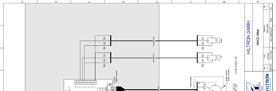
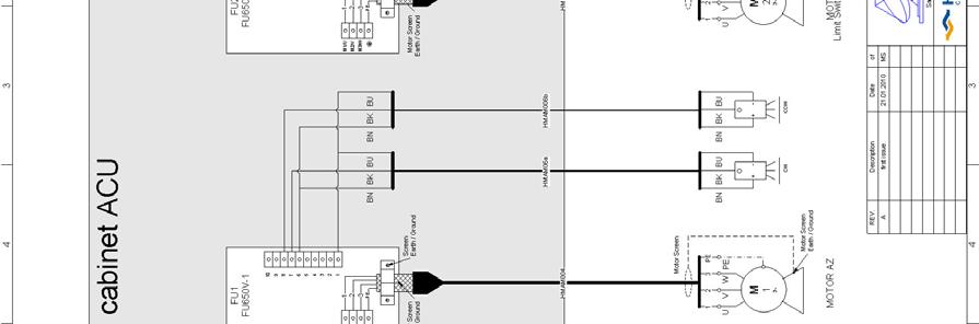
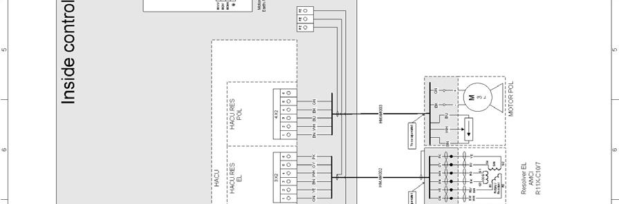
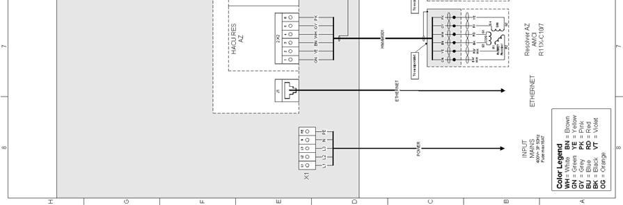
6 L1 L2 L3 N PE To encapsulatet GN YE BN WH GY PK BK/ RD/ WH WH S3 R1 Rotary / Resolver R2 COS S S4 SIN S2 To encapsulatet GN YE BN WH GY PK BK/ RD/ WH WH S3 R1 Rotary / Resolver R2 COS S1 S4 SIN S2 To encapsulatet 5 6 1~ PE PE PE M1/U M2/V M3/W PE 3~ CW CCW M1/U M2/V M3/W PE 3~ UP DOWN Hiltron GmbH HMAM_Install_A.doc Page 6 of 20 Inside control cabinet ACU FU1 FU650V-1 FU2 FU650V-1 HACU.RES AZ HACU HACU.RES EL HACU.RES POL * * BN BK BU BN BK BU * * BN BK BU BN BK BU Motor Screen Earth / Ground Screen Earth / Ground Motor Screen Earth / Ground Screen Earth / Ground J1 2.X2 3.X2 4.X2 X1 GN YE BN WH GY PK GN YE BN WH GY PK BN WH BU BK GN L1 L2 L3 N PE HMAM06a HMAM006b HMAM007a HMAM007b HMAM004 HMAM005 ETHERNET HMAM001 HMAM002 HMAM003 POWER Motor Screen Motor Screen BK GN BN WH BU PE PE - + U V W PE BN BK BU BN BK BU U V W PE BN BK BU BN BK BU BK RD BU YE BK RD BU YE M 3 M 1 O + - O + - M 2 O + - O + - INPUT ETHERNET MAINS 400V~ 3P 50Hz Fuse max16at Resolver AZ AMCI R11X-C10/7 Resolver EL AMCI R11X-C10/7 MOTOR POL Motor Screen Earth / Ground MOTOR AZ Motor Screen Earth / Ground MOTOR EL Limit Switch AZ Limit Switch EL HMAM AZ/EL Assembly, electrical interface Figure 5-3: Interface & electrical diagram of HMAM Electrical interface The HMAM is completely electrical integrated, tested and concerning parameter setting configured. There are only 3 electrical interfaces (see Figure 5-3) to be maintained: Terminals X1 Mains Power Supply (3 phases 400VAC or 1 phase 240VAC) J1 LAN connection RJ45 J2 Connector to Polarization drive assembly 6 Mechanical & Electrical Installation The HMAM allows the attachment of all kinds of reflectors with a diameter between 1.2M to 3.4M. The support is preferably adapted by Hiltron to the relevant type of antenna and its reflector. By default the design is selected for a 2.4m Ku-Band antenna System (e.g. Prodelin Serie ). The antenna mount should be suitable for the antenna to be integrated. should have a outer diameter 6 5/8 (~168 mm) to fit the HMAM rotating pedestal mount.
 3. Electrical Installation of HMAM 4. Set elevation position 20-30 5. Installation of antenna dish and feed support 6.")
7 HMAM_Install_A.doc Page 7 of 20 The installation has to be carried out in 6 (7) steps: 1. Mechanical Installation of mast mount 2. Mechanical Installation of HMAM (Azimuth and Elevation Drive Assembly) 3. Electrical Installation of HMAM 4. Set elevation position Installation of antenna dish and feed support 6. Installation of Polarization Drive Assembly 7. Final Testing and Calibration 6.1 Step1: Installation of Mast Mount As an example a Non Penetrating Mast Mount for a 2.4 m Antenna (NPMM for Antenna 1251 Footprint B) has been selected with a out diameter of 6 5/8. The installation of the mast mount should be performed according the guidelines of the Installation Manual Figure 6-1: NPMM for 2.4 m Antenna Deploy an position the mount according the supplier s instruction. Mount should be positioned such that the drop leg is aimed in the same direction as the azimuth heading of the antenna. It will allow clearance for the reflector a low lock angles. 6.2 Step 2: Mechanical Installation of the HMAM Fix the Azimuth and Elevation Drive Assembly to the adapter plate of the mast mount. (See Figure 6-2: )


.")
8 HMAM_Install_A.doc Page 8 of 20 Figure 6-2 Integration HMAM or mast mount The whole assembly should be arranged such that the antenna dish (mounted in a later stage) is pointing to the south (180 ) and fix the screws. Figure 6-3: Arrangement of HMAM 6.3 Step 3: Electrical Installation of HMAM Please follow the instructions for the electrical installation described in chapter Step 4: Set elevation position ~20 The HMAM is delivered when packed in elevation position ~80 (max. protected elevation jack screw and lowest size). The HMAM has to be put into operation to move the elevation position to to get easier access for mounting the antenna support and the dish. Please follow the instructions for the commissioning described in chapter 8

 Install first half of antenna")

9 HMAM_Install_A.doc Page 9 of Step 5: Installation of antenna dish & feed support a) Mount crossbar on HMAM main bracket Figure 6-4: Mounting the crossbar b) Install first half of antenna dish on the provided attachment points Attachment points Attachment points Attachment points Figure 6-5/6: Mounting the antenna dish


10 HMAM_Install_A.doc Page 10 of 20 Attachment points Attachment points Figure 6-7/8: Mounting the feed 6.6 Step 6: Installation of Polarization Drive Assembly In Figure 6-9/10 the polarization drive without feed is depicted. Front side Figure 6-9/10: Polarization drive Rear side The drive is assembled with the feed consisting of feed horn and OMT to the polarization drive assembly shown in figure 6-11/12.


11 HMAM_Install_A.doc Page 11 of 20 Rear side Front side Figure 6-11/12: Polarization drive assembly Please mount the polarization drive assembly to the provided rods of the feed support and connect the drive interface cable. Figure 6-13: Mounted polarization drive assembly
 has to be connected to the PE provided by the customer. It is recommended to ground the mast of the antenna via ground wire and clamp.")
12 HMAM_Install_A.doc Page 12 of 20 7 Electrical Installation (Steps) 7.1 Grounding For the HAMAM there is no external separate grounding point. On safety reasons the protective ground (see figure 17-1) has to be connected to the PE provided by the customer. It is recommended to ground the mast of the antenna via ground wire and clamp. The mast clamp must have a good electrical connection to the mast pole. However, each customer applies it own grounding and lightning protection concept to fulfill the general and national regulations. 7.2 Power and Network Connection For the power connection an flexible electric cable is required. Taking into account the total cable length and that a circuit breaker (16 Amp) on the power distributor is protecting the HMAM the correct cable type with the wire cross-section has to be selected accordningly. Root the electric cable through the provided feed-through (PG_M25 on rear bottom area of cabinet) and attach the wires to the terminals. By default a 3 phase power connection is provided. If only one phase is available, please use L1 and put bridges (see separate package in outdoor cabinet) from L1 to L2 and to L3. Root the network cable through the dedicated feed through (PG_M25 on front bottom area of cabinet) and connect this to the LAN connector (J1) on the antenna control. Figure 7-1: Power and network interface in HMAM Antenna Control Cabinet After the installation of power and network cables the antenna control is ready to operate and can be powered by switching on the circuit breakers (see F1 F5).
 installed.")

13 HMAM_Install_A.doc Page 13 of 20 8 Setting into Operation 8.1 Setting the IP Address In order to use the Web interface, the following prerequisites for a computer must be met: A standard web browser (e.g. Internet Explorer version 6 or higher) installed. Java Runtime Engine (JRE version 1.5 or higher) installed (can be downloaded from The antenna control unit has the default IP address setting of IP address Subnet Mask Default Gateway To configure the required IP address following procedure is proposed: Connect a computer via a crossover cable to the LAN connector J1 of the Antenna Control Unit. Configure the computer to the same network segment e.g. with following addresses IP-address Subnet Mask Set in Web browser the default IP address " " and open the web interface of the antenna control. The figure below shows the top view of the opened web interface Figure 8-1: Web interface of the Antenna Control Unit

14 HMAM_Install_A.doc Page 14 of 20 On the top the Web diagram you will find the menu line with the main menu items File and Download Figure 8-2: Menu items File and Download Select on the menu item Download the item HCS Tool and load down the Hiltron controller IP configuration program HCS Tool. With the start of the HCS tool program it is looking for all equipment accessible in the network and lists it with name and IP address. Figure 8-3: HCS Tool - control interface With an on the right click on the corresponding device the network configuration can be opened.

15 HMAM_Install_A.doc Page 15 of 20 Figure 8-4: Equipment addressing Set the new IP, Network Mask and Gateway address and confirm with the button Config. 8.2 Functionality Check and Adjustment of Axis Control The ACU setting is pre-adjusted to the default setting for control parameters. However, a final adjustment at lest a check of the setting parameters is necessary. Therefore a form has bee prepared to summarize and record all settings to document it as a final check of the functionalities. The list can be found on the end of the installation document (Annex 1) Check and Adjustment of Elevation Angle Eventually it can happen that the calibrated angle value is changed or in the worst case lost during the transport or antenna integration. Therefore please check the angle with an inclinometer and compare the result with the indicated value out of the Web-interface. In case there is a discrepancy please apply the procedure described in the document Manual_HMAM_en_A.doc: MANUAL for Monitoring & Control Antenna Control Unit HACU Click on button Elevation and select the tab Properties select the item Calibrate Angle set the correct value For a fine adjustment apply the same procedure when the geodetic latitude and the geodetic longitude is entered in the system ( of Manual_HMAM_en_A.doc) the antenna is pointed to a known satellite and the position is optimized.

.")

16 HMAM_Install_A.doc Page 16 of Check and Adjustment of Elevation Limit Switches The limit switches will be active when the metal plate is positioned above the sensors. This is the condition for normal operation with elevation angles within the allowed range. A limit alarm will be generated when the alarm contact is open (e.g. not connected sensor, broken line or a limit alarm when the sensor is not covered by the metal plate). Limit Switches Figure 8-5: Elevation limit switches (both active) In case the allowed Elevation angle range should be changed following steps become necessary: Open the housing for the Elevation resolver & limit switches Move the elevation of the antenna dish into the critical limit area you want to readjusted. Open the nut on one side of the metal plates carefully that these can be shifted slightly. Figure 8-6/7: Elevation limit switches adjustment
 Close the housing for the Elevation resolver & limit switches 8.2.")
17 HMAM_Install_A.doc Page 17 of 20 Turn the relevant metal plate in or from the direction to its dedicated limit switch. Fix the nut again which was opened before. Enter the new limit value into the form (see Annex 1) Close the housing for the Elevation resolver & limit switches Check and Adjustment of Azimuth Angle Point the antenna with the help of a compass into the south (180 ) and compare the result with the indicated value out of the Web-interface. The offset between the actual and the indicated value can be corrected applying the procedure described in the document Manual_HMAM_en_A.doc: MANUAL for Monitoring & Control Antenna Control Unit HACU Click on button Azimuth and select the tab Properties select the item Calibrate Angle set the correct value For a fine adjustment apply the same procedure when the geodetic latitude and the geodetic longitude is entered in the system ( of Manual_HMAM_en_A.doc) the antenna is pointed to a known satellite and the position is optimized Check and Adjustment of Azimuth Limit Switches The limit switches will be active when the metal plate is positioned above the sensors. This is the condition for normal operation with elevation angles within the allowed range. A limit alarm will be generated when the alarm contact is open (e.g. not connected sensor, broken line or a limit alarm when the sensor is not covered by the metal plate). Figure 8-8: Location of Azimuth limit switches


18 HMAM_Install_A.doc Page 18 of 20 Figure 8-9/10: Calibration of Azimuth limit switches In case the allowed Azimuth angle range should be changed following steps become necessary: Open the housing for the Azimuth resolver & limit switches Move the elevation of the antenna dish into the critical limit area you want to readjusted. Open the nut on one side of the metal plates carefully that these can be shifted slightly. Turn the relevant metal plate in or from the direction to its dedicated limit switch. Fix the nut again which was opened before. Enter the new limit value into the form (see Annex 1) Close the housing for the Azimuth resolver & limit switches Adjustment of Polarization Angle The angle value is pre-calibrated and cannot be changed manually. For fine adjustment please apply the procedure described in the document Manual_HMAM_en_A.doc: MANUAL for Monitoring & Control Antenna Control Unit HACU Polarization Limit Switches The limit switches are integrated in the housing and are calibrated. Therefore it is not necessary to set these values. The setting is documented in the form (s. Annex 1)
19 HMAM_Install_A.doc Page 19 of 20 Annex 1: Setting Protocol Function Specification Results Changes on Side Hardware Limits range of the antenna Azimuth to Elevation 1.75 to 67.2 Polarization to Software Limits range of the antenna Azimuth 125 to 240 Elevation 2 to 65 Polarization -45 to 60 Test manual positioning Antenna up, slow/fast Antenna down, slow/fast Antenna left, slow/fast Antenna right, slow/fast Polarization left, slow/fast Polarization right, slow/fast Positioning by angles Azimuth Elevation Polarization Antenna Emergency Stop no Alarm, error messages Limit switches Azimuth CW/ CCW Elevation DOWN/ UP Polarization CW/ CCW o.k.? o.k.? o.k.? o.k.? o.k.? o.k.? o.k.? o.k.? o.k.? Checked? Checked? Checked? Checked? Checked?
20 HMAM_Install_A.doc Page 20 of 20 Annex 2: HMAM Electrical Block Diagram
.84M Ku-Band Rx/O Antenna System
 4096-644 Revision A May 9, 2003 ASSEMBLY MANUAL.84M Ku-Band Rx/O Antenna System PRODELIN CORPORATION 1500 PRODELIN DRIVE NEWTON, NC 28658 .84M Ku-Band Rx/O Antenna System A ORIGINAL RELEASE 5/9/2003 A.Hahn
QDV120 Operation and Pointing manual
 QDV120 Operation and Pointing manual MPAD1 Plus OP-080316-E1 page 1 Contents Item Description Page 1.0 Health and Safety for Operators and Installation Staff 3 2.0 Transit case Reflector/Mount/BUC/LNB
1.2 METER SERIES 1130 Rx/O ANTENNA SYSTEM
 REVISION H April 20, 2016 ASSEMBLY MANUAL 1.2 METER SERIES 1130 Rx/O ANTENNA SYSTEM General Dynamics SATCOM Technologies 1700 Cable Drive NE Conover NC 28613 USA Phone 770-689-2040 www.gdsatcom.com 1.2
SERIES M Ku-BAND Rx / Tx ANTENNA SYSTEM
 4096-432 June 15, 2011 REVISION D ASSEMBLY MANUAL SERIES 1125 1.2M Ku-BAND Rx / Tx ANTENNA SYSTEM General Dynamics 1500 PRODELIN DRIVE NEWTON, NC 28658 PRODELIN CORPORATION 4096-432 SERIES 1125 1.2M Ku-BAND
1.2M Ku-BAND Rx/Tx SERIES 1132 ANTENNA SYSTEM
 August12, 2003 ASSEMBLY MANUAL Revision E 1.2M Ku-BAND Rx/Tx SERIES 1132 ANTENNA SYSTEM PRODELIN CORPORATION 1500 Prodelin Drive Newton NC 28658 1.2M Ku-BAND Rx/Tx SERIES 1132 ANTENNA SYSTEM E Revised
2005 ODU Point & Peak Job Aid
 Summary This Job Aid covers: Preparing the Antenna for Pointing and Peaking Point Elevation Set the Skew Point Azimuth Peak Azimuth Peak Elevation Push/Pull Test This Job Aid supports all Technician audiences.
PAP-240 Three Axis Antenna Pedestal and feed drive
 Présentation générale. ANTENNE MOTORISEE 3 AXES Versions : RxO Ku, RxO Ku&C (4 ports), RxTx Ku (2 ports), RxTx C (2 ports) PAP-240 Three Axis Antenna Pedestal and feed drive The two axis Motorized antenna
.98M Ku-BAND Rx/Tx ANTENNA SYSTEM
 Revision C January 2, 2002 ASSEMBLY MANUAL ANTENNA SYSTEM PRODELIN CORPORATION 1500 Prodelin Drive Newton NC 28658 ANTENNA SYSTEM C Revised Series text B Revised Address 1/2/02 RAH A Revise and Update
1.8 METER SERIES 1194 ANTENNA SYSTEM
 January 14, 2002 REVISION G ASSEMBLY MANUAL 1.8 METER SERIES 1194 ANTENNA SYSTEM PRODELIN CORPORATION 1500 Prodelin Drive Newton NC 28658 1.8 METER SERIES 1194 ANTENNA SYSTEM G Revise Address 1/14/02 F
Paradigm. Connect100 Installation Guide
 Paradigm GX Connect100 Installation Guide Paradigm GX Safe Use WARNING Radiation Hazard. Transmitter power levels are sufficient to cause blindness or other serious injury to body tissue. Do not power
1.8 METER SERIES 1184 ANTENNA SYSTEM
 REVISION F January 10, 2002 ASSEMBLY MANUAL 1.8 METER SERIES 1184 ANTENNA SYSTEM PRODELIN CORPORATION 1500 Prodelin Drive Newton NC 28658 1.8 METER SERIES 1184 ANTENNA SYSTEM F Revised Address 1/10/02
C-COM Satellite Systems Inc. Page 1 of 39
 Page 1 of 39 inetvu Fly-75V & Fly-98G/H/V & Fly-981 User Manual The inetvu brand and logo are registered trademarks of C-COM Satellite Systems, Inc. Copyright 2006 C-COM Satellite Systems, Inc. 1-877-iNetVu6
1.2M Ku-BAND Rx/Tx SERIES 1134 ANTENNA SYSTEM
 August 21, 1997 Revision D ASSEMBLY MANUAL 1.2M Ku-BAND Rx/Tx SERIES 1134 ANTENNA SYSTEM PRODELIN CORPORATION 1700 NE CABLE DRIVE CONOVER, NC 28613-0368 1.2M Ku-BAND Rx/Tx SERIES 1134 ANTENNA SYSTEM D
LinkAlign-360FER Set-up and Operation Manual
 LinkAlign-360FER Set-up and Operation Manual Proprietary, Nextmove Technologies Page 1 Proprietary, Nextmove Technologies Page 2 Table of Contents General Notes:... 4 Description of items included with
2009 ODU Point and Peak Job Aid
 Summary This Job Aid covers: Preparing the Antenna for Pointing and Peaking Point Elevation Set the Skew Point Azimuth Peak Azimuth Peak Elevation Push/Pull Test This Job Aid supports all Technician audiences.
MESA-HPX. Assembly and Installation Manual. w/appendix A for Prodelin Antenna. 901-Manual-MESA-HPX
 MESA-HPX Assembly and Installation Manual w/appendix A for Prodelin Antenna 901-Manual-MESA-HPX Rev 30 March 2011 2 INDEX Installation Cautions 4 Installation Pole Height Orientation of the Mount on the
Satellite Terminal. Installation Guide. Release 2.2 Ref. nr
 Satellite Terminal Installation Guide Release 2.2 Ref. nr. 37628 Table of Contents Table of Contents Table of Contents... 2 1 Introduction... 3 1.1 About this Guide... 3 1.2 Material Provided in the Box...
75cm ODU/SurfBeam 2 Point and Peak Job Aid
 Summary This Job Aid covers: 75cm ODU/SurfBeam 2 Point and Peak Job Aid Preparing the Antenna for Pointing and Peaking Configure the SurfBeam 2 Modem and 75cm TRIA Point Elevation Set the Skew Point Azimuth
LinkAlign-60RPT Set-up and Operation Manual
 LinkAlign-60RPT Set-up and Operation Manual LinkAlign Setup and Operation Proprietary, Nextmove Technologies Page 1 LinkAlign Setup and Operation Proprietary, Nextmove Technologies Page 2 Description of
Ground System Training Department
 Module 7: IPSTAR Uplink Access Test (IUAT) Ground System Training Department 2012-03-Standard (iuat1.14)-uti-101 THAICOM Public Company Limited Module Objectives At the end of the module the participant
RC2000. Cable Preparation ACU Installation Troubleshooting/Alarm codes. Patriot 1.8m
 RC2000 Cable Preparation ACU Installation Troubleshooting/Alarm codes Patriot 1.8m Installation Instructions I. Needed equipment: Multimeter, small flathead screwdriver, large phillips screwdriver,
M2 Antenna Systems, Inc. Model No:
 M2 Antenna Systems, Inc. Model No: 400-600-10 SPECIFICATIONS: Model... 400-600-10 Frequency Range... 390 To 650 MHz *Gain... 12 To 13 dbic Front to back... 20 db Nominal Beamwidth... 46 Nominal Feed Impedance....
Connecting the Radio:
 Connecting the Radio: Step 1: Connect the Cat5 cable from the radio into the RJ-45 jack marked CPE on the POE injector. The POE injector is not weather proof and should be installed indoors. Step 2: Connect
3 GHz Carrier Backhaul Radio. Model: AF-3X. Tel: +44 (0) Fax: +44 (0) LINK GPS MGMT DATA DATA
 Fax: +44 (0) LINK GPS MGMT DATA DATA") LINK GPS MGMT DATA DATA MGMT GPS LINK 3 GHz Carrier Backhaul Radio Model: AF-3X LINK GPS MGMT DATA 3 GHz Carrier Backhaul Radio Model: AF-3X LINK GPS MGMT DATA DATA MGMT GPS LINK Introduction Thank you
LINK GPS MGMT DATA DATA MGMT GPS LINK 3 GHz Carrier Backhaul Radio Model: AF-3X LINK GPS MGMT DATA 3 GHz Carrier Backhaul Radio Model: AF-3X LINK GPS MGMT DATA DATA MGMT GPS LINK Introduction Thank you
APPENDIX B - MOUNT SPECIFIC DATA for the Vertex 1.8m. FlyAway
 RC3000 Antenna Controller Appendix B Mount Specific Data 1 APPENDIX B - MOUNT SPECIFIC DATA for the Vertex 1.8m. FlyAway Revision: 14 December 2009, Software Version 1.60 1.1 Appendix B Organization This
Field Service Procedure Replacement Pol Motor Kit, Coastal
 1. Brief Summary: Troubleshooting document for diagnosing a fault with and replacing the pol motor on the Coastal series antennas. 2. Checklist: Verify Motor Drive Drive the Pol from Progterm Run the Built
Procedure, Field Replacement, PCU Kit, XX04
 1. Brief Summary: Troubleshooting document for diagnosing a fault with and replacing the XX04 series PCU assembly. 2. Checklist: Verify Initialization N0 Parameter Pedestal Error Test Motor 3. Theory of
Installation Guide. 2x2 MIMO Dish Antenna TL-ANT2424MD & TL-ANT5830MD
 Installation Guide 2x2 MIMO Dish Antenna TL-ANT2424MD & TL-ANT5830MD Contents Introduction 1 Specifications 1 Safety Notice 2 Package Contents 2 Installation Requirements 3 Hardware Overview 3 Hardware
APPENDIX B - MOUNT SPECIFIC DATA For VERTEX 2.4m. SM-LT
 RC3000 Antenna Controller Appendix B-Mount Specific Data B-1 APPENDIX B - MOUNT SPECIFIC DATA For VERTEX 2.4m. SM-LT This appendix describes RC3000 operations unique for the Vertex 2.4m. SM-LT mount. Revision
ANTENNA SYSTEMS. 1.8m Offset Rx & TxRx Antenna INSTALLATION & ASSEMBLY INSTRUCTIONS
 ANTENNA SYSTEMS.m Offset Rx & TxRx Antenna INSTALLATION & ASSEMBLY INSTRUCTIONS LIMITED TWELVE () MONTH WARRANTY This PATRIOT ANTENNA equipment is warranted to be free from defects in material and workmanship
GPSR400 Quick Start Guide
 GPSR400 Quick Start Guide Rev. 6 Introduction Microlab s digital GPS repeater system can be used for cellular communications UTC synchronization for locations where the GPS signals are not readily available.
Exercise 4. Angle Tracking Techniques EXERCISE OBJECTIVE
 Exercise 4 Angle Tracking Techniques EXERCISE OBJECTIVE When you have completed this exercise, you will be familiar with the principles of the following angle tracking techniques: lobe switching, conical
INSTALLATION INSTRUCTIONS
 Sheet 1 of 5 General: Upon receipt of fixture thoroughly inspect for any freight damage, which should be brought to the attention of the delivery carrier. Compare the catalog description listed on the
Absolute Encoders - Singleturn
 The Sendix 5853 and Sendix 5873 singleturn encoders with SSI or BiSS interface and optical sensor technology can achieve a resolution of max. 7 bits. These encoders are also available with an optional
Field Service Procedure PCU Kit, XX97, XX97A & XX00
 1. Brief Summary: Troubleshooting document for diagnosing a fault with and replacing the PCU assembly on the XX97, XX97A and XX00 series antennas. 2. Checklist: Verify Initialization N0 Parameter Pedestal
Antenna Pointing Guide
 Antenna Pointing Guide 1039429-0001 Revision B September 10, 2013 11717 Exploration Lane, Germantown, MD 20876 Phone (301) 428-5500 Fax (301) 428-1868/2830 Copyright 2013 Hughes Network Systems, LLC All
Quick Start Instructions EMV-INspektor V2
 Connecting the : The illustration below shows the connection diagram for the. Step 1: Before connecting the to the voltage supply, first establish the connection of the to the measuring clamp adapters.
LINK GPS MGMT DATA. 4 GHz Licensed Backhaul Radio DATA MGMT GPS. Model: AF-4X LINK
 LINK GPS MGMT DATA DATA MGMT GPS LINK 4 GHz Licensed Backhaul Radio Model: AF-4X 4 GHz Licensed Backhaul Radio Model: AF-4X LINK GPS MGMT DATA DATA MGMT GPS LINK Introduction Thank you for purchasing the
RC3000/ RC3050 INTERFACE SPECIFICATIONS
 RC3000/ RC3050 INTERFACE SPECIFICATIONS Research Concepts, Inc.; Lenexa, KS 66215; PH: (913)469-4125; FAX: (913)469-4168 WWW.RESEARCHCONCEPTS.COM SUPPORT@RESEARCHCONCEPTS.COM Overview The RC3000 Satellite
Procedure, Field Replacement, PCU Kit, 6003A/6004, 2406 & 4003A
 1. Brief Summary: Troubleshooting document for diagnosing a fault with and replacing the PCU assembly on the 6003A/6004, 2406 & 4003A series antennas. 2. Checklist: Verify Initialization N0 Parameter Pedestal
Assembly Manual for the 1.2m Quick-Deploy Antenna System
 704 North Clark Street Albion, MI 49224 USA Phone +1 517 680 0125 Fax +1 517 680 0133 www.challengercommunications.com Challenger Communications Assembly Manual for the 1.2m Quick-Deploy Antenna System
Elliptical Unpacking and Installation Instructions
 Elliptical Unpacking and Installation Instructions Use these instructions for the following Ellipticals: ClubStride 5100-LE Receiving When the carrier delivers your order, verify that the number of items
Absolute Encoders - Singleturn
 The Sendix 5 and Sendix 7 singleturn encoders with SSI or BiSS-C interface and optical sensor technology can achieve a resolution of max. 7 bits. These encoders are also available with an optional SinCos
74CM KU-BAND TYPE 741 ANTENNA SYSTEM HIGH WIND with Factory Assembled Az/El Mount
 JULY 2016 Revision A ASSEMBLY MANUAL 8001114-01 74CM KU-BAND TYPE 741 ANTENNA SYSTEM HIGH WIND with Factory Assembled Az/El Mount A ORIGINAL RELEASE - EC-02522 JUL 2016 R. Thompson REV. DESCRIPTION DATE
ANTENNA SYSTEMS. PTX Offset Antenna.60/.76/.90./1.1m INSTALLATION & ASSEMBLY INSTRUCTIONS
 ANTENNA SYSTEMS PTX Offset Antenna.60/.76/.90./1.1m INSTALLATION & ASSEMBLY INSTRUCTIONS LIMITED TWELVE (12) MONTH WARRANTY This PATRIOT ANTENNA equipment is warranted to be free from defects in material
AC and DC solutions- Multiple AC and DC solutions available, please contact factory for your application.
 The ATX-3000 antenna tracking controller is a user-friendly microprocessor-based intelligent positioning system to reliably track inclined orbit satellites or for use as a positioner for geosynchronous
RT-21 Az-El Controller Manual addendum to RT-21 - August 5, 2014
 RT-21 Az-El Controller Manual addendum to RT-21 - August 5, 2014 Overview: The RT-21 Az-El controller consists of two RT-21 units with a shared power supply and shared chassis. The unit features a pair
Pole Mount Installation Guide
 Pole Mount Installation Guide (No Fine Adjustment) 495R Billerica Ave. North Billerica, MA 01862 USA Tel (978)459-8800 fax (978)459-3310 / 8814 Email: sales@radiowaves.com www.radiowaves.com IMPORTANT!
Installation Job Aid (English) for Avaya WLAN 8100 series- WLAN AP 8120 with External Antenna
 for Avaya WLAN 8100 series- WLAN AP 8120 with External Antenna") Release 3.0 NN47251-311 Issue 02.01 June 2014 Installation Job Aid (English) for Avaya WLAN 8100 series- WLAN AP 8120 with External Antenna How to get help To access the complete range of services and
Release 3.0 NN47251-311 Issue 02.01 June 2014 Installation Job Aid (English) for Avaya WLAN 8100 series- WLAN AP 8120 with External Antenna How to get help To access the complete range of services and
Session 5. VSAT installation and Maintenance 1/74
 Session 5 VSAT installation and Maintenance 1/74 Sample Hardware list The VSAT system consists of the following hardware: The Outdoor Unit assembly The Indoor Unit assembly 2/74 Sample Hardware list The
Specifications Sheet: PRIME FOCUS MESH DISH KIT 1.2 Meter DISH
 Specifications Sheet: PRIME FOCUS MESH DISH KIT 1.2 Meter DISH Available F/D: 0.35 / 0.4 / 0.45 / 0.5 (Example Picture: 1.2 Meter dish (6mm mesh) 1M2_KIT_SPEC RF HAMDESIGN www.rfhamdesign.com This 8-Rib
SDR 4++ Dual Diversity SDR Receiver. Operating Guide. version 1.0
 Cross Country Wireless, 7 Thirlmere Grove, BOLTON, BL4 0QB, UK Email chrism@crosscountrywireless.net Web page http://www.crosscountrywireless.net Telephone +44 (0) 1204 410626 Mobile / Workshop +44 (0)
Installation Instructions
 903-CIS0143-C Installation Instructions 0.9m Antenna LEAX Arkivator Telecom disclaims any liability for the results of improper or unsafe installation, inspection, maintenance, or removal practices. Torsgatan
GPSR116 Quick Start Guide
 GPSR116 Quick Start Guide .21 [ 5,3] [482,6] 18.12 [460,3] GPSR116 Quick Start Guide Rev 2.35 [8,9] Introduction Microlab s digital GPS repeater system can be used for cellular communications UTC synchronization
These Installation Instructions are valid for antennas in the following version:
 Installation Instructions 4 ft CompactLine Antennas (with E-Mount 200 km/h) SB, SBX NMT 480-12(e) These installation instructions have been written for qualified, skilled personnel. The antenna shall be
Absolute Encoders Singleturn
 The absolute singleturn encoders Sendix 5853 SIL and 5873 SIL are perfectly suited for use in safety-related applications up to SIL3 according to DIN EN ISO 6800-5- or PLe to DIN EN ISO 3849. The extra
1.15m (45 ) Linear Ka-Band Maritime Stabilized VSAT System. For O3b System
 Linear Ka-Band Maritime Stabilized VSAT System. For O3b System") Installation Guide - 1.15m (45 ) Linear Ka-Band Maritime Stabilized VSAT System For O3b System Doc P/N: MAN34-0659 Rev.X1 OceanTRx 4-500 O3b System Installation Guide Copyright 2014 Orbit Communication
Installation Guide - 1.15m (45 ) Linear Ka-Band Maritime Stabilized VSAT System For O3b System Doc P/N: MAN34-0659 Rev.X1 OceanTRx 4-500 O3b System Installation Guide Copyright 2014 Orbit Communication
75 cm ODU (VS1300) Assembly Job Aid
 Assembly Job Aid") Summary This Job Aid covers: Verify AZ/EL Assembly Alignment Antenna Back Bracket Assembly Transport On Site Assembly This Job Aid supports all Technician audiences. This job aid covers the VS1200 ODU
Summary This Job Aid covers: Verify AZ/EL Assembly Alignment Antenna Back Bracket Assembly Transport On Site Assembly This Job Aid supports all Technician audiences. This job aid covers the VS1200 ODU
HANDLING AND ASSEMBLY INSTRUCTIONS FOR TRUE FOCUS 3.0M, 3.8M AND 4.2M ANTENNAS WITH POLAR MOUNT
 HANDLING AND ASSEMBLY INSTRUCTIONS FOR TRUE FOCUS 3.0M, 3.8M AND 4.2M ANTENNAS WITH POLAR MOUNT Introduction SECTION 1 Thank you for purchasing one of our fine True Focus products. This manual covers the
THIS SHOULD TWEAK YOUR IMAGINATION
 10-27-05 THIS SHOULD TWEAK YOUR IMAGINATION SPECIFICATIONS FOR SINGLE ANTENNA MODEL NUMBER... 432EME-12 FREQUENCY... 430-436 MHz GAIN... 14.4 dbd FRONT TO BACK... 23 db VSWR... 1.2:1 TYPICAL BEAMWIDTH...
APPENDIX B - MOUNT SPECIFIC DATA For SweDish Radar Finder
 RC3000 Antenna Controller Appendix F RC3000 Data Sheet 1 APPENDIX B - MOUNT SPECIFIC DATA For SweDish Radar Finder This appendix describes RC3000 operations unique for the SweDish Radar Finder mount. Differences
TL4100 Top 5 Build Tips
 TL4100 Top 5 Build Tips 1: Top Plate When assembling the top plate, align the top of the top plate brackets with the top of the rods. This can be done by placing a hard flat object (such as a ruler) on
ANTENNA SYSTEMS. 67cm/84cm Offset Antenna Receive only and Transmit-Receive Micro-Terminal INSTALLATION & ASSEMBLY INSTRUCTIONS
 ANTENNA SYSTEMS 67cm/84cm Offset Antenna Receive only and Transmit-Receive Micro-Terminal INSTALLATION & ASSEMBLY INSTRUCTIONS LIMITED TWELVE () MONTH WARRANTY This PATRIOT ANTENNA equipment is warranted
WINEGARD. Movin View
 WINEGARD TM Movin View Digital Satellite Mobile Antenna for Single Receiver Model MV-0055 Made in the U.S.A. U.S. Patent Nos. 6,023,247; 6,188,300 Winegard Company 3000 Kirkwood St. Burlington, IA 52601-2000
Absolute Encoders Multiturn
 Absolute Encoders Multiturn Functional Safety, optical The absolute multiturn encoders Sendix 5863 SIL and 5883 SIL are perfectly suited for use in safety-related applications up to SIL3 according to DIN
Installation Guide Flat Panel Antenna Mounting Kit For
 Installation Guide Flat Panel Antenna Mounting Kit For 103670-1 495R Billerica Ave. North Billerica, MA 01862 USA Tel (978)459-8800 fax (978)459-3310 / 8814 Email: sales@radiowaves.com www.radiowaves.com
CHC i80 GNSS Receiver QuickTour with LandStar7. (PDA Network Mode)
") CHC i80 GNSS Receiver QuickTour with LandStar7 (PDA Network Mode) 1.Prerequisites Hardware: CHC i80 rover, Controller Kit, SIM card,lithium Battery, pole Software: LandStar7 2.Steps to set i80 working
CHC i80 GNSS Receiver QuickTour with LandStar7 (PDA Network Mode) 1.Prerequisites Hardware: CHC i80 rover, Controller Kit, SIM card,lithium Battery, pole Software: LandStar7 2.Steps to set i80 working
AW58300HTA AW58300HTS USER S MANUAL
 AW58300HTA AW58300HTS USER S MANUAL 5.8 GHz Outdoor 300 Mbps Wireless Ethernet Access Point and Subscriber Unit Radios Industrial-grade, long-range wireless Ethernet systems AvaLAN W I R E L E S S The
HiSeasNet Maintenance Visit Report (Template dated 13 November 2007)
") HiSeasNet Maintenance Visit Report (Template dated 13 November 2007) Page 1 Ship Visited: Ship Location/Port: R/V Oceanus Woods Hole, Massachusetts Date(s) of work: 23, 24 June 2008 Work performed by:
HiSeasNet Maintenance Visit Report (Template dated 13 November 2007) Page 1 Ship Visited: Ship Location/Port: R/V Oceanus Woods Hole, Massachusetts Date(s) of work: 23, 24 June 2008 Work performed by:
Rotary Fixture M/V/X CLASS LASER SYSTEMS. Installation and Operation Instructions
 Rotary Fixture M/V/X CLASS LASER SYSTEMS Installation and Operation Instructions 02/01/2000 Introduction The Rotary Fixture controls in the Printer Driver are used along with the optional Rotary Fixture
75 cm ODU (VS1300 with the SurfBeam2 TRIA) Assembly Job Aid
 Assembly Job Aid") Summary This Job Aid covers: Verify AZ/EL Assembly Alignment Antenna Back Bracket Assembly TRIA, TRIA Bracket, and Boom Arm Assembly This Job Aid supports all Technician audiences. This job aid covers
Summary This Job Aid covers: Verify AZ/EL Assembly Alignment Antenna Back Bracket Assembly TRIA, TRIA Bracket, and Boom Arm Assembly This Job Aid supports all Technician audiences. This job aid covers
AvaLAN AW58103HTS MANUAL ADDENDUM. 5.8 GHz Outdoor 100 Wireless 3-Port Ethernet Subscriber Unit Radio
 AW58103HTS MANUAL ADDENDUM 5.8 GHz Outdoor 100 Wireless 3-Port Ethernet Subscriber Unit Radio Industrial-grade, long-range wireless Ethernet systems AvaLAN W I R E L E S S AW58103HTS Addendum The AW58103HTS
Remarks: Before Installation, please read the instruction carefully.
 30 cm antenna Z24A30T37301 Remarks: Before Installation, please read the instruction carefully. This instruction book is for the installation of 0.3m ultra-high performance microwave antenna. Installation,
1 1. Before you begin, please read the following guide lines.
 1 1. Before you begin, please read the following guide lines. 2. Open the Two Boxes A. Unpack the two boxes carefully. B. Take out all accessories and check everything is included. 3. Setting up the Antenna.
APPENDIX B - MOUNT SPECIFIC DATA For. Patriot 3.8m Mobile Antenna
 RC Antenna Controller Appendix B Mount Specific Data 1 APPENDIX B - MOUNT SPECIFIC DATA For Patriot.8m Mobile Antenna REVISION HISTORY 29 December 26, Software Version 1.58 27 October 29, Software Version
Antenna Control Outdoor Unit AC User Manual
 sat-nms ACU-ODU-AC Antenna Control Outdoor Unit AC User Manual Version 4.4 / 2018-01-04 Copyright SatService Gesellschaft für Kommunikatiosnsysteme mbh Hardstrasse 9 D-78256 Steisslingen www.satnms.com
MILL ONE. Assembly Manual. Manual Illustrated by Gontarz Design Studio
 MILL ONE Assembly Manual Manual Illustrated by Gontarz Design Studio Safety Warnings and Guidelines 1. Be sure to carefully follow provided machine assembly instructions before machine use to ensure operator
11 GHz FDD Licensed Backhaul Radio. Model: AF 11FX
 11 GHz FDD Licensed Backhaul Radio Model: AF 11FX 11 GHz FDD Licensed Backhaul Radio Model: AF 11FX Introduction Thank you for purchasing the Ubiquiti Networks airfiber AF 11FX. This Quick Start Guide
Rotary Encoder System Compact Model Range
 we set the standards RIK Rotary Encoder System Compact Model Range 2 Incremental rotary encoder Features Compact design, consisting of scanning head with round cable, 15pin D-sub connector and grating
8861 Controller Electrical Installation 9-/10-/11-Meter
 8861 Controller Electrical Installation 9-/10-/11-Meter Manual 42S060C April 2003 Notice All Rights Reserved The information contained in this document is proprietary to ViaSat, Inc. This document may
Rotary Measurement Technology Absolute Encoders, Multiturn
 Mechanical drive Safety-LockTM High rotational speed -40 to 90 C IP Temperature High IP High shaft load capacity Shock/ vibration resistant Magnetic field proof Short-circuit proof Reverse polarity protection
Sole Fitness E95 Elliptical Trainer TurnKey Delivery and Setup Training
 Sole Fitness E95 Elliptical Trainer TurnKey Delivery and Setup Training Delivery Requirements Ground delivery Inside delivery to customer-specified location Unpack and assemble machine, and remove packing
Type 100 and Type 120 SMC Antenna System 1.0 Meter and 1.2 Meter Reflector with Az/El Cap Mount
 Assembly Instructions Type 100 and Type 120 SMC Antenna System 1.0 Meter and 1.2 Meter Reflector with Az/El Cap Mount 8000284-01 Skyware Global 1315 Industrial Park Drive Smithfield, NC 27577 USA Telephone:
inetvu Service Manual
 inetvu Service Manual Page 1 of 109 inetvu Service Manual The inetvu brand and logo are registered trademarks of C-COM Satellite Systems, Inc. Copyright 2006 C-COM Satellite Systems, Inc. 1-877-iNetVu6
Remarks: Before Installation, please read the instruction carefully.
 60 cm antenna Z24A60T37301 Remarks: Before Installation, please read the instruction carefully. This instruction book is for the installation of 0.6m ultra-high performance microwave antenna. Installation,
1.2M KU-BAND TYPE 128 ANTENNA SYSTEM HIGH WIND with Factory Assembled Az/El Mount
 September 2015 Revision A ASSEMBLY MANUAL 8001101-01 1.2M KU-BAND TYPE 128 ANTENNA SYSTEM HIGH WIND with Factory Assembled Az/El Mount A ORIGINAL RELEASE EC-02178 OCT 2015 R. Thompson REV. DESCRIPTION
I n s t a l l a t i o n M a n u a l. T E D P r o L i t e A B C. f o r. Shop for The Energy Detective products online at: Rev 3.
 Rev 3.5 I n s t a l l a t i o n M a n u a l f o r T E D P r o H o m e T E D P r o L i t e A B C Shop for The Energy Detective products online at: 1.877.766.5412 IMPORTANT: The installation of your TED
Standard Pole Mount Parabolic Antenna Mounting Instructions 3 ft. (90cm) & 4 ft. (120cm)
 & 4 ft. (120cm)") 495 R Billerica Ave. N. Billerica, MA 01862 USA Tel: (978) 459-8800 Fax: (978) 459-3310 / 8814 www.radiowavesinc.com email: sales@radiowavesinc.com Standard Pole Mount Parabolic Antenna Mounting Instructions
495 R Billerica Ave. N. Billerica, MA 01862 USA Tel: (978) 459-8800 Fax: (978) 459-3310 / 8814 www.radiowavesinc.com email: sales@radiowavesinc.com Standard Pole Mount Parabolic Antenna Mounting Instructions
LIGHT BEAM ANTENNA MaxRange Antenna Series Assembly Instructions MaxRange Ultra Digital / High Definition Television Antennas
 LIGHT BEAM ANTENNA MaxRange Antenna Series Assembly Instructions MaxRange Ultra Digital / High Definition Television Antennas Assembly Instructions 1 MaxRange Ultra Antenna These instructions will lead
IG-2500 OPERATIONS GROUND CONTROL Updated Wednesday, October 02, 2002
 IG-2500 OPERATIONS GROUND CONTROL Updated Wednesday, October 02, 2002 CONVENTIONS USED IN THIS GUIDE These safety alert symbols are used to alert about hazards or hazardous situations that can result in
Exercise 6. Range and Angle Tracking Performance (Radar-Dependent Errors) EXERCISE OBJECTIVE
 EXERCISE OBJECTIVE") Exercise 6 Range and Angle Tracking Performance EXERCISE OBJECTIVE When you have completed this exercise, you will be familiar with the radardependent sources of error which limit range and angle tracking
Exercise 6 Range and Angle Tracking Performance EXERCISE OBJECTIVE When you have completed this exercise, you will be familiar with the radardependent sources of error which limit range and angle tracking
Hughes. Installation Manual for.74 m Ku-band Upgradeable Antenna Model AN6-074S
 Hughes Installation Manual for.74 m Ku-band Upgradeable Antenna Model AN6-074S 1036469-0001 Revision D March 31, 2006 Copyright 2005, 2006 Hughes Network Systems, LLC All rights reserved. This publication
Instruction and Assembly Manual
 Instruction and Assembly Manual.90m, 1.0m & 1.2m SMC ANTENNA SYSTEM WITH AZ/EL CAP MOUNT TYPE 900 -.9m TYPE 100-1.0m TYPE 120-1.2m SMC ANTENNA WITH AZ/EL CAP MOUNT (UK) Limited Premier Business Park, Croft
Antenna Control Unit (ACU) Graphical User Interface (GUI) Software Instruction Manual
 Graphical User Interface (GUI) Software Instruction Manual") ISO 9001:2015 Certified Antenna Control Unit (ACU) Graphical User Interface (GUI) Software Instruction Manual Quasonix, Inc. 6025 Schumacher Park Dr. West Chester, OH 45069 19 July 2018 Revision 1.5 Software
ISO 9001:2015 Certified Antenna Control Unit (ACU) Graphical User Interface (GUI) Software Instruction Manual Quasonix, Inc. 6025 Schumacher Park Dr. West Chester, OH 45069 19 July 2018 Revision 1.5 Software
Base Station Commissioning
 CHAPTER 7 Base Station Commissioning In This Chapter: Commissioning Overview, page 78 Alarms, page 80 Receiver Sensitivity Test, page 81 Transmit Power Tests, page 87 Network Connection and Ping Test,
2.4m Offset Antenna Receive only and Transmit-Receive
 2.4m Offset Antenna Receive only and Transmit-Receive LIMITED TWELVE (12) MONTH WARRANTY This PATRIOT ANTENNA equipment is warranted to be free from defects in material and workmanship under normal use
2.4 Meter 4 Piece C-Band Rx/Tx Antenna Feed System
 4096-354 Revision B July 14, 2009 ASSEMBLY MANUAL 2.4 Meter 4 Piece C-Band Rx/Tx Antenna Feed System General Dynamics 1500 PRODELIN DRIVE NEWTON, NC 28658 2.4 Meter C-Band Rx/Tx Antenna Feed System B Revised
DJA3000. Cellular Communication Jammer. Installation and Operations Manual. Series DJA3000. Description: Cellular Communication Jammer
 DJA3000 Cellular Communication Jammer Installation and Operations Manual Series DJA3000 Description: Cellular Communication Jammer Models: DJA3040 and DJA3120 Series DJA3000 up to 4 Bands Thank you for
User Manual CTP4/8/16
 KMT - Kraus Messtechnik GmbH Gewerbering 9, D-83624 Otterfing, Germany, 08024-48737, Fax. 08024-5532 Home Page http://www.kmt-telemetry.com, Email: info@kmt-telemetry.com User Manual CTP4/8/16 4/8/16-channel
MPA-9000 Universal Ceiling Projector Mount Kit
 I N S T R U C T I O N M A N U A L Universal Ceiling Projector Mount Kit The Universal Ceiling Projector Mount provides a unique, simplified method of ceiling mounting your inverted projector. This low