BOILER MANAGEMENT SYSTEM
|
|
|
- May Lynn Shaw
- 6 years ago
- Views:
Transcription

1 BOILER MANAGEMENT SYSTEM
2 g y ( )
3 Table of Contents Page SECTION 1 ABOUT YOUR NEW BOILER MANAGEMENT SYSTEM (BMS) 1-1 SECTION 2 FEATURES OF THE BMS 2-1 SECTION 3 INSTALLING THE BMS MOUNTING THE BMS GENERAL WIRING Pulse Width Modulation Wiring At the BMS Pulse Width Modulation Wiring At the Boiler SENSOR INSTALLATION AND WIRING Header Sensor Outside Air Sensor 3-3 SECTION 4 FAMILIARIZING YOURSELF WITH THE BMS ABOUT BMS MODES Selecting and Viewing Functions 4-1 4,1,2 Changing Function Settings NORMAL MODE FUNCTIONS HDR TEMP 4-4 4,2,2 AIR TEMP % LOAD SYS START TEMP REF TEMP HDR TEMP LIMIT FIELD ADJ SET POINT PROP BAND OFF SET RESET RATIO and Arrow Keys ON and OFF Keys CONFIG SYS FIELD ADJUST MODE FUNCTIONS HDR TEMP AIR TEMP % LOAD Setting the Internal Clock With the % LOAD Key SYS START TEMP REF TEMP HDR TEMP LIMIT FIELD ADJ SET POINT 4-7 i
4 Table of Contents (Continued) Boiler Management system (BMS) PROP BAND OFF SET Setting Up a Reset Schedule RESET RATIO and Arrow Keys ON and OFF Keys CONFIG SYS SYSTEM CONFIGURATION MODE FUNCTIONS TEMP FAIL MODE SYS ENABLE MAX PWR INPUT START AND STOP LEVEL Keys BLR OP MODE Sequential Mode Parallel Mode Combination Mode Designating the Number of Combination Boilers HDR SET MODE INTGL RATE GAIN and DERIV GAIN Keys TEMP BANDWIDTH INTGL RATE GAIN AUX RELAY and Arrow Keys ON and OFF Keys CONFIG SYS 4-14 SECTION 5 PROGRAMMING THE BMS MODE OF OPERATION 5.1 INDOOR/OUTDOOR RESET MODE Selecting Indoor/Outdoor Reset Mode Entering System Start Temperature Determining the Reset Schedule Entering the Building Reference Temperature Entering the Reset Ratio SETUP FOR 4-TO-20-MA REMOTE SETPOINT MODE Entering Header Set and Boiler Operating Modes Entering Building Reference Temperature SETUP FOR CONSTANT SETPOINT MODE Entering Header Set and Boiler Operating Mode Entering Header Reference Temperature CONFIGURING THE TEMPERATURE CONTROLLER FOR PULSE WIDTH MODULATION Temperature Controller Addressing Configuring the Temperature Controller 5-4 ii
5 Table of Contents (Continued) Boiler Management system (BMS) 5.5 SYSTEM INITIALIZATION AND POLLING TESTING THE SYSTEM 5-4 APPENDICES Appendix A Specifications A-1 Appendix B Methods for Determining Reset Schedule and Indoor/Outdoor Reset Ratio Charts B-1 Appendix C Normal (Read-Only) Mode Display Messages and Defaults C-1 Appendix D Field Adjust Mode Display Messages and Defaults D-1 Appendix E Config Sys Mode Display Messages and Defaults E-1 Appendix F Sensor Resistance Data Sheet F-1 Appendix G Parts List G-1 Appendix H Troubleshooting H-1 Appendix I General BMS Wiring I-1 Appendix J Programming the BMS Using RS-232 Communication J-1 iii
6 List of Figures Figure 1 Typical BMS Installation 3-4 Figure 2 BMS Mounting 3-5 Figure 3 Wire Routing Locations at the BMS 3-6 Figure 4 PWM Communication Outputs at the BMS 3-7 Figure 5 Pulse Width Modulation Connections at KC Series Boiler Boiler With Modular Control Box 3-8 Figure 6 Pulse Width Modulation Connections at KC Series Boiler Boiler With C-More Control Box 3-9 Figure 7 Pulse Width Modulation Connections at the Benchmark Figure 8 Boiler With Modular Control Box 3-10 Pulse Width Modulation Connections at the Benchmark Boiler With C-More Control Box 3-11 Figure 9 Header Sensor Installation With Well 3-12 Figure 10 Outside Air Sensor Mounting and Connections 3-13 Figure 11 Normal and Field Adjust Mode Overlay 4-2 Figure 12 System Configuration Mode Overlay 4-3 iv
7 Section 1 About Your New Boiler Management Sy stem (BMS) AERCO s Boiler Management System (BMS), stages and modulates AERCO KC Series and Benchmark boilers, allowing them to operate efficiently as a system. It provides a broad array of operating modes, so that the nuances of specific applications can be easily accommodated. The BMS will control eight boilers via pulse width modulation communication. PRECISE CONTROL Utilizing Pulse Width Modulation (PWM), the BMS fully exploits the condensing and modulating ability and efficiency of each boiler and regulates the output of the boiler plant with water supply temperature variation of no more than ±2 F Staging can be performed sequentially or in parallel. The BMS can sample building reference temperatures to modulate boiler plant output, and will perform water supply temperature night setback automatically referenced to its internal clock. SIMPLE INSTALLATION AND OPERATION Installation of the BMS is simple, and lowvoltage wiring is employed between the BMS panel and boiler modules. There are no complex design steps to be performed, since a keypad in conjunction with the LCD allows the operator to acquire, change, and program settings through easy-to-use labeled buttons. Each BMS function consists only of selecting the function and toggling values, which generally requires no more than pressing four keys. The instant a parameter is programmed, it is automatically entered into the BMS memory, avoiding multiple programming steps to store information. In the event of power loss, most factory default settings remain in nonvolatile memory for up to 10 years and need not be reprogrammed. However, date and time remain in memory for about 30 days. RS232 COMMUNICATION If desired, the BMS can be programmed by connecting a Laptop Computer, or other type of terminal emulation device, to the RS232 connector on the front panel. See Appendix J for programming using RS232 communication.. 1-1
8 g y ( )
9 Section 2 Features of the BMS APPLICATION FLEXIBILITY Three different system or control options can be selected at setup to match the needs of any closed-loop system - Indoor/Outdoor Reset, 4-to-20 ma Remote Setpoint, and Constant Setpoint. CONTINUOUS COMMUNICATIONS The BMS continually sends information to the boilers and receives information from them, providing total control of boiler plant dynamics. EXCEPTIONAL ACCURACY The BMS control system uses a PID (Proportional Integral Derivative) control algorithm to respond dynamically to system changes. Water temperatures are precisely controlled by modulating energy in put. A supply water temperature of ±2 F is assured. BUILDING INDOOR AIR TEMPERATURE INPUTS The BMS accepts building indoor air temperatures directly from a thermistor sensor or from a 4-to-20 ma signal. Adjustments can be made to the header setpoint temperature to compensate for varying building temperatures and conditions. SEQUENTIAL OR PARALLEL OPERATION Modules can be either sequenced on, or run in parallel, by selection from the front panel. In sequential mode, boilers are brought on one at a time, so turn-down ratio is 14 multiplied by the number of KC Series boilers, or 15 multiplied by the number of Benchmark boilers. This provides higher energy savings and seasonal efficiency. In parallel mode, all of the boilers are modulated together at the same firing rate. The turn-down ratio of the system is fixed at 14:1 for the KC Series boilers and 15:1 for the Benchmark boilers. BUMPLESS TRANSFER When in sequential mode, the BMS stages boilers on and off, one at a time, at selectable percentages of firing rate. The result is a seamless transition and undetectable room temperature changes. Sequential mode has several other unique features: Run-Time Equalization: The BMS sequences boilers on a first on-first off basis, which automatically equalizes the run time of all boilers in the plant. Automatic Load Distribution: The BMS continuously monitors the number of modules that are available for operation. In the event of a boiler malfunction or when service is performed, the BMS automatically compensates for a lack of response from any unit and brings on the next available boiler to satisfy demand. This feature operates in both parallel and sequential modes. 2-1
10 Time Delay Between Boiler Starts: A fixed, 30-second time delay between boiler starts ensures smooth energy input without spikes in electrical, gas, or venting conditions. AUTOMATIC SYSTEM START Automatic system start contacts for controlling auxiliary equipment such as pumps and dampers can be selected to close between 32 F and 100 F outside air temperature, eliminating the need for the plant operator to turn auxiliary equipment on and off. MINIMUM AND MAXIMUM HEADER SET CLAMPING The supply water temperature can be clamped at a maximum high temperature or minimum low temperature, to ensure that the building temperature is optimal for the greatest comfort. Two Interlock Circuits (Enable/Disable Contacts) The BMS contains two normally-open interlock circuits that require only a set of dry contacts to enable or disable the boiler plant. They can be used to monitor pumps, combustion air dampers, or other equipment. Out-of-limit conditions trip the interlocks, shutting down the boiler plant, and providing a high level of protection. ADJUSTABLE OFFSET The Offset feature can allow the temperature of the supply water to be offset in 1 increments over a range of -50 F below to +50 F above its current temperature. This feature is employed for night setback or morning warmup. The BMS lets you select, over a 7-day period, the time when the offset begins and ends. CONTROL OF AUXILIARY EQUIPMENT The auxiliary relay uses a dry set of contacts to operate auxiliary equipment. For example, when the boiler plant is at 100% load, these contacts close and can start an auxiliary boiler, or notify an energy management system of a full-load condition. FAULT ALARM SURVEILLANCE The BMS continually monitors its sensors for opens and shorts and the interlock circuits for opens. However, the BMS fault relay does not close or indicate when a boiler has failed. The alarm circuit consists of a dry set of 120 VAC contacts rated at 5 A. SIMPLE INSTALLATION The BMS operates from 120 VAC, 50 to 60 Hz, and uses Belden 9841 or equivalent wiring between modules for control and monitoring. The lightweight panel can be mounted up to 200 feet from the boilers when using pulse width modulation communication. RUGGED AND RELIABLE The BMS is housed in a NEMA 13-grade enclosure and operates in ambient temperatures as high as 131 F (55 C). POWER-OFF MEMORY Most system configuration values are retained in nonvolatile memory for up to 10 years. Date and time remain in memory for approximately 30 days. 2-2
11 Section 3 Installing the BMS Please follow the installation procedure in the order presented. Incorrect wiring may damage the unit and void the AERCO warranty Do not omit steps, and do not substitute other types of wiring for those specified. Figure 1 shows a typical BMS installation. 3.1 MOUNTING THE BMS Use the mounting plate (Figure 2) supplied with the BMS to securely mount the unit away from moisture, and at an appropriate height for easy reading of the display. To reduce the possibility of electrical noise entering the system, mount the BMS at least 6 feet away from electrical devices such as power panels, high voltage transformers and transmission lines, motors, and fluorescent lights. All wiring and fusing must be in compliance with the National Electrical Code and with local electrical codes. Control wiring for the sensors and communications links must run in separate conduit and not in the conduit providing line voltage in order to ensure immunity from electrical noise. All wiring should be installed in conduit leading up to the bottom of the BMS panel. There are five knock-outs in the bottom of the panel by which wiring must enter the BMS. 3.2 GENERAL WIRING Belden 9841 polyethylene-jacketed, shielded twisted-pair cable or equivalent should be used for all wiring. All power wiring should be at least 18 AWG and no more than 16 AWG. Signal and probe wiring should be at least 22 AWG and no more than 18 AWG. A complete BMS wiring diagram is included as Appendix H. Once mounting is complete and the BMS is securely in place, remove the wiring cover plate screws with a Phillips screwdriver. Feed all wiring through the knock-outs provided on the bottom of the panel. All pulse-width modulation control wires should be fed through the knock-outs furthest left. Shock Hazard! Extreme caution must be exercised when wiring the BMS. Line voltage to the area of the BMS must be turned off to avoid electrical shock Power wiring should be fed through the right-most knock-outs in the bottom of the panel (Figure 3). The two remaining knockouts are for control wiring located on the middle terminal block. The terminal blocks can be detached from the BMS to make field wiring easier. Once power wiring is complete, turn on the line voltage to the BMS, and turn on the BMS to verify proper connection. The display should show INITIALIZING EPROM REV. n where n is the current EPROM version. 3-1
12 3.2.1 Pulse Width Modulation Wiring At the BMS WARNING! Turn off AC input power from the BMS to avoid electrical shock. To wire boilers for pulse width modulation (PWM), connect the boiler control wires (Belden 9841 recommended) in ascending order according to the numbers on the BMS (Figure 4). For example, the control wiring for boiler 1 at the BMS would be connected as follows: Positive control wire connects to JP 2, terminal 1 (positive). Negative control wire connects to JP 2, terminal 2 (negative). Shield wiring connects to the negative control wire at Section BLR 1, terminal 2. The shield is not terminated at the boiler. All shields must be terminated on the BMS end. The wiring terminals labeled SHIELD at terminal block JP3 of the BMS are not internally connected to ground and are only used as a place to terminate the sensor shields. The pulse width modulation shield can be connected to any minus (-) terminal of the PWM terminal strip (JP2) Pulse Width Modulation Wiring At The Boiler The pulse-width modulation (PWM) control wiring from the BMS to each boiler is connected at each boiler s relay box or input/output (I/O) box, depending on the type of control system used. Modular control systems utilize a relay box as shown in Figure 5 (KC1000) and Figure 7 (Benchmark). The newer C-More control system utilizes an I/O box as shown in Figure 6 and Figure 8. Regardless of the type of control system used, the PWM wiring is connected to the BMS + and terminals as shown in the respective illustrations. It is imperative that positive (+) and negative (-) polarity be observed when making these connections. All boilers follow the same control wiring scheme. When using pulse width modulation, the BMS may be mounted up to 200 feet from the boilers. 3-2
13 3.3 SENSOR INSTALLATION AND WIRING There are two types of sensors that may be installed -- header sensors and outside air sensors. While an outside air sensor is required for Indoor/Outdoor Reset mode, it is not required for Constant Setpoint or 4-to- 20-mA modes of operation. However, it is recommended to take full advantage of all BMS features. The header sensor is required for all modes of operation. Sensor wiring and power wiring should be run separately to reduce the chance of electrical noise entering the sensor wiring Header Sensor The header sensor to be used with the BMS is a sensor that requires a well as shown in Figure 9. When installing the sensor, use a 1/2 inch NPT tapped coupling or a 4 x 4 x 1/2 T fitting. Use heat-conductive grease when installing to aid in its response. The sensor probe must be inserted at least 2 inches into the flow of water for proper response. The header sensor must be installed between 2 and 10 feet downstream of the LAST boiler in the plant s supply water header. Belden 9841 cable is recommended for header sensor wiring. There is no polarity to be observed. Connect the wires from the sensor to BMS terminals 4 and 5 on JP3. The ground for the shield is at BMS end of the link, not the header sensor. Connect the ground to JP3, terminal 8 (SHIELD). The header sensor can be installed up to 600 feet from the BMS Outside Air Sensor The Outside Air Sensor, AERCO part no. GP , must be mounted on the North side of the building, shielded from direct sunlight, and away from air intakes or outlets from the building. See Figure 10 for a typical installation. The sensor includes a plate for wall mounting. Belden 9841 cable, or equivalent, is recommended for sensor wiring. There is no polarity to be observed. Connect the sensor wires to BMS terminals 1 and 2 on JP3. Connect the shield to JP3, terminal 3 (SHIELD) at the BMS. The shield must not be grounded on the sensor end. The sensor can be mounted up to 600 feet from the BMS. The header sensor is a thermistor type sensor. The Resistance vs. Temperature Charts for the sensor are provided in Appendix F. See Figure 9 for installation details. 3-3
14 g y ( ) 3-4
15 Figure 2 BMS MOUNTING 3-5
16 Figure 3 RECOMMENDED WIRE ROUTING LOCATIONS AT THE BMS 3-6
17 Figure 4 PWM COMMUNICATION OUTPUTS AT THE BMS 3-7
18 Figure 5 PULSE WIDTH MODULATION CONNECTIONS AT KC SERIES BOILER WITH MODULAR CONTROL BOX 3-8
19 Remove sheet metal cover to access I/O Box OUTDOOR SENSOR IN SENSOR COMMON AUX SENSOR IN NOT USED + ANALOG IN - + B.M.S. (PWM) IN - SHIELD REMOTE INTL'K IN EXHAUST SWITCH IN DELAYED INTL'K IN NOT USED NC COM NO NC COM NO FAULT RELAY 120 VAC, 5A, RES NOT USED AUX RELAY 120 VAC, 5A, RES + ma OUT - RS G COMM. - NOT USED PWM Connections Figure 6 PULSE WIDTH MODULATION CONNECTIONS AT KC SERIES BOILER WITH C-MORE CONTROL BOX 3-9
20 Figure 7 PULSE WIDTH MODULATION CONNECTIONS AT BENCHMARK BOILER WITH MODULAR CONTROL BOX 3-10
21 Figure 8 PULSE WIDTH MODULATION CONNECTIONS AT BENCHMARK BOILER WITH C-MORE CONTROL BOX 3-11
22 1/2 NPT Figure 9 HEADER SENSOR INSTALLATION WITH WELL 3-12
23 Figure 10 OUTSIDE AIR SENSOR MOUNTING AND CONNECTIONS 3-13
24 g y ( )
25 Section 4 Familiarizing Yourself With the BMS 4.1 ABOUT BMS MODES The BMS has three basic modes: Normal Mode, Field Adjust Mode and Configure System Mode. The Normal Mode is a Read-Only mode which only allows you to view system settings. The Field Adjust (FIELD ADJ) Mode and System Configuration (CONFIG SYS) Mode allow you to view or change BMS settings to customize and tune the system to the specific needs of your site. The BMS keypad normally displays the functions applicable to the Normal and Field Adjust Mode. However, the keys perform slightly different functions for Normal and Field Adjust Modes. When operating in the System Configuration Mode, you must install the SYSTEM CONFIGURATION OVERLAY sheet, supplied with the BMS, over the keypad. Figures 9 and 10 show the Normal/Field Adjust layout and the System Configuration keypad layouts respectively Selecting and Viewing Functions As previously mentioned, the Normal mode, is a read-only mode which allows functions to be viewed, but not changed. However, functions associated with the keypad keys can also be viewed in the FIELD ADJ and CONFIG SYS modes, provided the appropriate mode key (FIELD ADJ or CONFIG SYS) is first selected. For example, pressing the HDR TEMP key displays the supply water temperature. You can view all mode functions by simply pressing its associated key. You must be in the System Configuration mode (CONFIG SYS) to view the functions associated with the SYSTEM CONFIGURATION OVERLAY Changing Function Settings To change, rather than simply display settings and functions, the BMS must be in the FIELD ADJ or CONFIG SYS mode. To change a function value, press the and arrow keys until the display shows the desired selection. Once you change the value, associated with one or more function keys they are automatically stored in nonvolatile memory. For example, if you change the values for three separate functions in the Field Adjust mode, you don t need to exit and then re-enter the mode for each function change. The following paragraphs describe the operation of the BMS keypad for each mode. In addition, tabular listings summarizing keypad operation for each mode are provided in Appendices C, D and E. Ensure that 120 Vac power is supplied to the BMS and the ON key LED is illuminated. If the LED is not illuminated, press the ON key. 4-1

26 Figure 11 NORMAL & FIELD ADJUST MODE OVERLAY 4-2

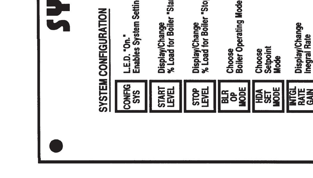

27 O 00 Figure 12 SYSTEM CONFIGURATION MODE OVERLAY 4-3
28 NOTE Sample Normal Mode displays with their Factory Default values are provided in Appendix C. 4.2 NORMAL MODE DISPLAYS AND FUNCTIONS When power is applied to the BMS, it is automatically placed in the Normal Mode. It allows you to view the settings currently stored in memory for BMS parameters. In addition, you can enter the Field Adjust or System Configuration Mode by pressing the FIELD ADJ or CONFIG SYS key. The functions provided by the keypad keys are described in the following paragraphs HDR TEMP Pressing and releasing this key displays the actual header sensor water temperature in F. Pressing and holding this key displays the header setpoint temperature presently stored in memory AIR TEMP Pressing and releasing this key displays the actual outside air temperature. Pressing and holding this key displays the actual inside air temperature, only if an indoor air temperature sensor is installed. If an indoor air sensor is not installed, INDOOR AIR TEMP NOT CONNECTED will be displayed % LOAD Pressing and releasing this key displays the actual firing rate percentage (% Load) for the boiler plant. It also displays the number of boilers presently operating SYS START TEMP Pressing and holding this key displays the System Start Relay temperature setting in F presently stored in memory. The system will start whenever the outside air temperatures drops below this setting REF TEMP Pressing and holding this key displays the Header Reference Temperature in F presently stored in memory HDR TEMP LIMIT Pressing and holding this key displays the header high limit temperature setting ( F) stored in memory FIELD ADJ Pressing and releasing this key places the BMS in the Field Adjust Mode and lights the FIELD ADJ key LED. When this key is pressed, the display will read FLD ADJUSTMENT MAKE SELECTION. Refer to paragraph 4.3 for key functions when in this mode SET POINT Pressing and holding this key displays the indoor setpoint temperature ( F) stored in memory PROP BAND Pressing this key displays the indoor air proportional bandwidth. This bandwidth is a variable used in an equation that solves for the proper offset of supply water temperature based on an indoor air temperature. Normally the display will read INDOOR PROP BAND 00.0 F/ F. See paragraph for additional information OFFSET Pressing and holding this key displays the Header Temperature Offset ( F) for the present time and day-of-the-week. See paragraph for additional information on setting up an offset schedule RESET RATIO Pressing and holding this key will display the header reset ratio if a value is currently stored in memory. This function is only used in the Indoor/Outdoor Reset Mode. If this function is not set, or the Constant Setpoint or Remote (4-20 ma) mode is used, the display will show FUNCTION NOT VALID. Also, ALARM CANCEL is printed directly above this key. Pressing and releasing this key will open the Alarm Relay contacts until the Alarm condition reappears. 4-4
29 and Arrow Keys The and arrow keys are not active in this mode, since no changes can be made to the displayed settings ON and OFF Keys Pressing and releasing the ON or OFF key enables or disables the BMS. In addition, the corresponding key LED will light when the key is pressed CONFIG SYS Pressing and releasing this key places the BMS in the System Configuration Mode and lights the CONFIG SYS key LED. When this key is pressed, the display will read CONFIG. SYSTEM MAKE SELECTION. Refer to paragraph 4.4 for key functions when in this mode. NOTE Sample Field Adjust Mode displays with their Factory Default values are provided in Appendix D. Boiler Management system (BMS) reading in F. This is also a Read Only display and cannot be changed % LOAD The % LOAD key has two separate and distinct functions in the Field Adjust Mode. Pressing and holding this key displays the actual firing rate (load) percentage and the number of boilers presently operating. Releasing the % LOAD key changes its function to Setting the Internal Clock as described in the following paragraph Setting the Internal Clock With The % LOAD Key Pressing and releasing the % LOAD key changes the first line of the display to SET TIME CLOCK. The second line of the display will show: MONTH, DATE, YEAR, DAY, HOURS, or MINS. Since these functions wrap around, it is strongly suggested that you repeatedly press the % LOAD key until the display shows MONTH: in the second line. This will make the following steps easier to follow: 4.3 FIELD ADJUST MODE DISPLAYS AND FUNCTIONS The Field Adjust Mode allows you to view or change settings currently stored in memory for BMS parameters. Many of the settings in this mode have been preset by AERCO to their Factory Defaults. However, you can reset many functions to suit the specific needs of your BMS installation. The following discussion refers to the functions of the keys. The Field Adjust Mode is entered by simply pressing the FIELD ADJ key and verifying that the FIELD ADJ key LED lights HDR TEMP Pressing and holding this key displays the actual header sensor water temperature in F. This is a Read Only display and cannot be changed AIR TEMP Pressing and holding this key displays the actual outside air temperature sensor NOTE When performing the following steps, use the and arrow keys to increment or decrement the displayed value. Pressing and holding the or key will change the displayed value at a rapid rate. 1. Press key until MONTH: is displayed. Set the actual number of the month (1-12). 2. Press key again to display DATE:. Set the actual day of the current month (1-31). 3. Press key again to display YEAR:. Set the last 2 digits of the year. 4. Press key again to display DAY:. Set the day that you want to be the first day of the week. AERCO normally sets Sunday as DAY 1, however any day of the week can be set as DAY 1. For example, if the actual DATE (day of month) entered in step 2 is a Monday, and you want Monday to be the first day 4-5
30 of the week, set DAY: to 1. Conversely, if you want to retain Sunday as the first day of the week, set DAY: to 2 to indicate you are currently in the second day of the week. 5. Press key again to display HOURS:. Set the hours using the 24-hour format (0 to 23). 6. Press key again to display MINS:. Set the minutes (0 to 59). 7. This completes the Internal Clock settings SYS START TEMP When in the Field Adjust Mode, the SYS START TEMP key has two functions. First, It lets you select the outdoor temperature at which the system starts. Second, it lets you select the system start option (TEMP ONLY or TEMP AND LOAD). For example, with the system start temperature set at 70 F (SYS. START RELAY 70 F), the system start relay will close and enable the boilers when the outside air temperature falls to 69 F (or lower). To always enable the boilers, regardless of the system start temperature, or if an outside air temperature sensor is not used, see paragraph in the System Configuration Mode section. Pressing and releasing the SYS START TEMP key once displays the System Start Relay temperature. (AERCO presets System Start to an outside air temperature of 70 F). Pressing and releasing this key a second time displays the System Start Option which can be set to either outside air temperature only (TEMP ONLY) or outside air temperature and load (TEMP AND LOAD). To change Start Option, press or key to toggle the setting. If TEMP ONLY is chosen, the BMS will close the system start relay contacts when the outdoor air temperature drops below the Boiler Management system (BMS) 4-6 system start temperature setting, without regard to load. The TEMP AND LOAD feature is used when the System Start Relay will control dampers. It keeps dampers closed until it is necessary to open them for combustion. This is designed to ensure that cold air is not always entering the boiler room. If TEMP AND LOAD is chosen, two conditions are necessary for the system start relay contacts to close and enable the boilers. First, the firing rate (displayed as % LOAD) must be above 11%. Second the outdoor air temperature must be below the system start temperature. The system start relay contacts will open when the load percentage falls below 7% REF TEMP The REF TEMP key has two functions, depending on the operating mode used by the boilers connected to the BMS. In the Indoor/Outdoor Reset Mode, pressing and releasing this key displays the Building Reference Temperature. In the Constant Setpoint Mode, pressing this key displays the header supply water temperature setpoint (HEADER REF. TEMP). To change the displayed Reference Temperature, press the or arrow key HDR TEMP LIMIT This key allows you to view or change the low and high temperature limits for the header supply water temperature. In addition, when in the 4-to-20 ma Remote Setpoint Mode, it automatically scales the 4- to-20 ma signal. Accordingly, 4 ma will be equal to the header low limit setting and 20 ma will be equal to the header high limit setting. Pressing and releasing this key once displays the header high limit temperature (HDR HIGH LIMIT).
31 Pressing and releasing this key a second time displays the header low limit temperature (HDR LOW LIMIT). Pressing and releasing this key a third time displays the header offset temperature (HEADER OFFSET). To change the displayed header high, low or offset temperature limits, press the or arrow key. Boiler Management system (BMS) temperature. The schedule can be set up for a 7-day period. Pressing and releasing this key once will display OFFSET ENABLE followed by OFF or ON (Default is OFF). If an Offset Schedule will be used, toggle the display to ON using the or arrow key. See paragraph for step-by-step procedures on how to set up an Offset Schedule FIELD ADJ The FIELD ADJ key LED should be lit to indicate that the BMS is already in the Field Adjust Mode. Pressing and releasing this key when already in the Field Adjust Mode will cause the BMS to exit the Field Adjust Mode and switch the BMS to the Normal (Read-Only) Mode SET POINT Pressing and releasing this key allows you to view or change the indoor setpoint temperature. This function is only used when an indoor air temperature sensor is connected to the BMS. If used, the input can be provided by a resistive type sensor, or a 4-to-20 ma input PROP BAND Pressing this key displays the indoor air proportional bandwidth. This bandwidth is a variable used in an equation that solves for the proper offset of supply water temperature based on an indoor air temperature. Normally, the display will read INDOOR PROP BAND 00.0 F/ F. AERCO presets the proportional bandwidth to F/ F. It should NOT be readjusted unless your system has an indoor air temperature sensor and is operating in the Indoor Setpoint mode. If the indoor temperature feature is not being used, PROP BAND MUST be set to F/ F or the BMS will not run the boiler plant OFFSET The OFFSET key is used to enable and set up an Offset Schedule for the header supply IMPORTANT Prior to setting up a Reset Schedule, refer to the paragraph to determine which Day of the Week has been set as Day 1. AERCO presets Day 1 of the week as Sunday. However, any day of the week can be specified as Day 1 by performing the steps outlined in paragraph Setting Up A Reset Schedule The basic steps for setting up a Reset Schedule consist of first selecting the temperature offset and then entering the start and stop times for which the offset will be in effect. Keep in mind that the BMS uses a 24-hour clock (00:00 to 23:59). In the following example, for Day 1, we want to offset the setpoint temperature by -15 F starting at 12:30 am (00:30) and return it to the normal setpoint at 8:15 am (08:15). Proceed as follows: 1. Press OFFSET key once and toggle the display to OFFSET ENABLE ON. 2. Press key a second time. OFFSET TEMP DAY 1 is displayed prompting entry of the offset temperature. Set the offset temperature to -15 using the and arrow keys. 3. Press key a third time. OFFSET ON TIME DAY 1 0: 0 is displayed prompting Hours to be entered for the start time. Set the Hours to zero (midnight) using the and arrow keys. 4-7
32 4. Press key a fourth time. OFFSET ON TIME DAY 1: 0 0 is displayed, prompting Minutes to be entered for the start time. Set the Minutes to 30 using the and arrow keys. 5. Press key a fifth time. OFFSET OFF TIME DAY 1 0: 0 is displayed prompting Hours to be entered for off time. Since the BMS uses a 24-hour clock format, set the Hours to 8 using the and arrow keys. 6. Press key a sixth time. OFFSET OFF TIME DAY 1: 8 0 is displayed prompting Minutes to be entered. Set the Minutes to 15 using the and arrow keys. 7. This completes the steps for setting the Offset Temperature, and Start/Stop Times for Day 1. For a 7-Day Schedule, the above steps would be repeated as needed. Offset Schedule entries stored in memory can be reviewed by repeatedly pressing the OFFSET key as needed RESET RATIO The Reset Ratio is only used in the Indoor/Outdoor Reset Mode of operation. This ratio the amount that the supply water temperature will rise for each degree drop in outside air temperature. A reset ratio of 2.0 means that the supply water temperature will increase 2 F for every 1 F decrease in outdoor air temperature. For example, if the building reference temperature is set at 70 F, when outside air temperature drops to 69 F, and the reset ratio is 1.8, the water supply temperature will increase to 71.8 F. AERCO presets the Reset Ratio to 1.2 F/ F. See Appendix B for Reset Ratio Charts. Pressing and releasing this key will display the Header Reset Ratio ( F/ F) if a value is currently stored in memory. When operating in the Constant Setpoint or Remote (4-20 ma) mode, the display will show FUNCTION NOT VALID. Boiler Management system (BMS) and Arrow Keys These keys are used to increment ( ) or decrement ( ) the displayed variable, or toggle the display through available options. When these keys are depressed and held the displayed value will increment or decrement at a rapid rate ON and OFF Keys Pressing and releasing the ON or OFF key enables or disables the BMS. In addition, the corresponding LED will light when the corresponding key is pressed CONFIG SYS When the BMS is in the Field Adjust Mode, this key has two functions. First, it allows you to select the types of faults which will cause an alarm. Second, it allows you to select how alarms are cleared. Pressing and releasing the CONFIG SYS key once displays the FAULT ALARM RELAY status and allows you to select the types of faults which will cause an alarm. The choices are: ALL FAULTS, NO INTERLOCK, INTERLOCK 2 or INTERLOCK 1. Selecting ALL FAULTS causes the BMS Fault Relay to close and generate an alarm when either Interlock 1 or Interlock 2 opens. Selecting INTERLOCK 2 causes the Fault Relay to close and generate an alarm only when Interlock 2 opens. However, if INTERLOCK 1 opens, a fault message will be generated but the Fault Relay will not be closed. Selecting INTERLOCK 1 causes the Fault Relay to close and generate an alarm only when Interlock 1 opens. However, if INTERLOCK 2 opens, a fault message will be generated but the Fault Relay will not be closed. Selecting NO INTERLOCK causes the Fault Relay to remain open and not generate an alarm when either Interlock 1 or Interlock 2 opens. It should be noted
33 however that the BMS will always shut down the boilers when Interlock 1 or 2 opens, regardless of the selected Fault Relay option. Select the desired option using the or arrow keys. Pressing and releasing the CONFIG SYS key a second time displays FAULT ALARM CLEAR and allows you to select how faults are cleared. The available choices are MANUAL RESET or AUTOMATIC. Toggle to the desired option using the or arrow key. Prior to placing the BMS in the System Configuration Mode, the FIELD ADJ key must be pressed to exit the Field Adjust Mode. Pressing and releasing the CONFIG SYS key places the BMS in the System Configuration Mode and lights the CONFIG SYS key LED. When this key is pressed, the display will read CONFIG. SYSTEM MAKE SELECTION. Refer to paragraph 4.4 for key functions when in this mode. NOTE Sample System Configuration mode displays with their Factory Default values are provided in Appendix E. 4.4 SYSTEM CONFIGURATION MODE DISPLAYS AND FUNCTIONS The System Configuration Mode allows you to program and operate the BMS to effectively run and manage the performance of the boiler plant. In order to effectively use this mode, the SYSTEM CONFIGURATION OVERLAY provided with the BMS must be placed over the keypad for proper identification of key functions (Figure 12). The System Configuration Mode is entered by simply pressing the CONFIG SYS key and verifying that the CONFIG SYS key LED lights. Boiler Management system (BMS) The keys described in the following paragraphs allow you to view or change settings currently stored in memory. If the desired setting is not displayed for the selected BMS parameter, press the or arrow key to increase, decrease or toggle the displayed setting. All changes made will be stored in memory TEMP FAIL MODE Pressing and holding this key displays the actual header sensor water temperature in F. This is a Read Only display and cannot be changed. Pressing and releasing this key allows you to display and select a Temperature Failure Mode (TEMP FAIL MODE) of either SHUTDOWN or SWITCH INPUTS. If SHUTDOWN is selected, regardless of the operating mode, the BMS will shut down the boiler plant whenever a temperature sensor fails or either interlock opens. If the BMS is operating in the 4-to-20-mA mode, the BMS will also shut down the boiler plant if the 4-to-20-mA signal drops below 3 ma. If any of these failures occur, the fault relay will close and the BMS will display the appropriate failure message. If SWITCH INPUTS is selected, the BMS will automatically switch to Constant Setpoint mode if a sensor or remote input error occurs. Once the sensor or remote input error has been cleared, the BMS will automatically switch to the previous mode. When selecting SWITCH INPUTS, the reference temperature for the Constant Setpoint mode must be preset. See Section 5 for programming steps. Regardless of whether SHUTDOWN or SWITCH INPUTS is selected, the BMS will shut down and close the fault relay contacts if the header sensor circuit fails. 4-9
34 4.4.2 SYS ENABLE Pressing and releasing this key allows you to select the INTERLOCK 1 enable setting of START ENABLED or ALWAYS ENABLED. The START ENABLED feature will not enable the boiler plant until the outside air temperature falls below the system start temperature. If the boiler plant begins to operate and Interlock 1 is open, the BMS will wait 30 seconds before stopping the boilers and displaying a fault message. This feature is intended for use with auxiliary equipment having limit switches. For instance, dampers with proving end switches, can be triggered by the BMS system start relay or the boiler s AUX relay as the boilers start. If the dampers do not open, the end switch wired to Interlock 1 will not make (close) and the BMS will shut down the boilers. The ALWAYS ENABLED feature allows the boilers to run, regardless of the system start and outside air temperature settings. This feature is used when there is a loss of an outside air sensor or one is not installed. It will also function if an outside air temperature sensor is present. It should be noted that if either Interlock 1 or 2 opens, the BMS will shut down the boilers. The system start relay will close only after the outside air temperature falls below the system start temperature, whether START ENABLED or ALWAYS ENABLED is selected. AERCO recommends that the system be equipped with a flow switch that is interlocked to the BMS. This is especially important if ALWAYS ENABLED is selected and the BMS is controlling the pumps based on outside air temperature, or the BMS is interfaced with an energy management system that is controlling the pumps MAX PWR INPUT This key is used to establish the maximum firing rate percentage for the boilers being controlled by the BMS. If desired, the maximum firing rate of the boilers can be Boiler Management system (BMS) 4-10 limited to values below 100%. This is useful if there are problems with gas supply pressure. For example, if gas pressure is too low, the boilers can be run at a lower firing rate temporarily until proper gas pressure can be restored. Pressing the MAX PWR INPUT key displays the maximum allowable firing rate percentage for the boilers START LEVEL and STOP LEVEL Keys These keys allow you to set the energy levels (firing rate percentages) at which additional boilers are staged-in or stagedout of the system during Sequential or Combination mode operation. While the start level can be set at any percentage up to 100%, it is best to keep it below 60%. This allows the system to operate at optimum efficiency under low loads. The BMS is preset with 45% start and 18% stop levels, which generally provide the best performance. When changing the start or stop levels, it is important to remember that load-balancing affects bumpless transfer. A sufficiently wide gap between the start and stop levels must be maintained to prevent cycling between units. For example, in a two-boiler system with a start level of 60% and a stop level of 30%, when the first boiler reaches 60%, the BMS will distribute the load between the two boilers, so that each will have a firing rate of 30%. However, since the stop level is 30%, the BMS will automatically shut down one boiler and allow the firing rate of the second boiler to increase to 60%. The BMS will then repeat this undesirable cycling. To avoid this, the start level could be set to 65%, leaving the stop level at 30%. When the BMS distributes the load after the first boiler reaches a 65% firing rate, the individual load would be 32.5%, sufficiently above the stop level. Conversely, the stop level could be changed to 25%, leaving the start level at 60%. In this case, when the BMS distributes the load, there will be 5% margin between this load (30%) and the stop level (25%).
35 Pressing the START LEVEL key displays firing rate percentage at which the boilers will start. Pressing the STOP LEVEL key displays firing rate percentage at which the boilers will stop BLR OP MODE This key is used to select the Boiler Operating Mode. It allows you to make choices concerning the effective and efficient way to fire the boilers based on the building load. The mode choices include: Parallel, Sequential, or Combination Mode. Pressing the BLR OP MODE key displays BOILER OP MODE followed by the currently selected mode (PARALLEL, SEQUENTIAL or COMBINATION). AERCO presets the mode to SEQUENTIAL. If necessary, use the and arrow keys to toggle between the 3 available modes. The following paragraphs describe the advantages of each mode selection. Boiler Management system (BMS) 25% for each boiler. If the firing rate of both boilers reach the start level, a third boiler is started by the BMS (after a 30 second delay), and the load will be distributed across all three boilers. This sequence will continue base on load demand and the number of boilers connected to the BMS. As the load drops off, the firing rates decrease. When all boilers reach the stop level, the first boiler turned on will be shut off by the BMS and its load will be evenly distributed to the remaining firing boilers. This off-sequencing continues until only one boiler is left firing. The last boiler will turn off when its stop level is reached Parallel Mode When operating in Parallel Mode, the boilers are simultaneously started by the BMS. The start and stop levels have no effect when in Parallel Mode. The turn-down ratio in Parallel Mode is fixed at 14:1 for KC 1000 Series boilers and 15:1 for Benchmark boilers, regardless of the number of boilers in the plant Sequential Mode The Sequential Mode provides a greater turn-down ratio than Parallel Mode. This is because the turn-down ratio in Sequential Mode is equal to the number of boilers multiplied by 14 for KC Series boilers and by 15 for Benchmark boilers. In Parallel Mode, the turn-down ratio is fixed at 14:1 for KC Series boilers and 15:1 for Benchmark boilers, and does not consider the number of boilers in the plant. In Sequential Mode, each boiler is started one at a time based on the load and start/stop levels programmed in the BMS. The BMS will start a single boiler when there is a load demand. Once the first boiler reaches the start level, a second boiler will be started and the load will be distributed evenly between the two boilers Combination Mode Combination mode is used only when the boiler plant will be used to satisfy both space heating and domestic hot water needs. This configuration, known as a Combination System, is used in conjunction with an AERCO Combination Control Panel (CCP). This system uses BMS-mode boilers dedicated to space heating and Combination boilers that are primarily used to satisfy the domestic hot water need. The domestic combination boilers are also available for the space heating load when the domestic hot water load is satisfied. This is accomplished using a motorized valve and storage tank equipped with a heat exchanger. For more information concerning the Combination System, see AERCO s CCP-1 literature. For instance, if a start level of 50% is chosen, when the first boiler reaches 50% a second boiler will start (after a 30 second delay), and the BMS will distribute the load 4-11
36 Designating the Number of Combination Boilers Up to 4 combination boilers can be connected to the BMS. However, when using the Combination Mode, it is necessary to tell the BMS how many combination boilers there are, and their size in millions of BTUs (MBTUs). This is accomplished as follows: 1. With the COMBINATION MODE selected, press the BLR OP MODE key. The display will read: COMBINATION MODE X OF CCP BOILERS, (where X is the number of Combination boilers). 2. Enter the number of Combination boilers connected to the BMS using the and arrow keys. 3. Press the BLR OP MODE key again. The display will read: COMBINATION MODE X OF.5MBTU BLR. 4. Enter the number of.5mbtu boilers (if any) connected to the BMS using the and arrow keys. 5. Press the BLR OP MODE key again. The display will read: COMBINATION MODE X OF 1 MBTU BLR. 6. Enter the number of 1 MBTU boilers (KC1000 Series) connected to the BMS using the and arrow keys. 7. Press the BLR OP MODE key again. The display will read: COMBINATION MODE X OF 2 MBTU BLR. 8. Enter the number of 2 MBTU boilers (Benchmark Series) connected to the BMS using the and arrow keys. 9. This completes the entries required for COMBINATION MODE operation. IMPORTANT When connecting combination boilers to the BMS, it is important that you start at the BLR 8 terminals on Terminal Strip JP2 and work towards BLR 1. Boiler Management system (BMS) HDR SET MODE This key has two functions. First, it is used to select the Indoor/Outdoor Reset, Constant Setpoint, or Remote 4-to-20-mA boiler mode operation. Second, it is used to select the type of indoor temperature sensor used with the BMS, if one is installed. The type of sensor can be either resistive (thermistor) or a constant voltage signal with current varying from 4 to 20 ma. Pressing the HDR SET MODE key once selects the Header Set Mode function. If the desired mode is not displayed, toggle the display to the desired mode (IN/OUTDOOR RESET, REMOTE (4-20ma.) or CONSTANT SETTEMP) using the or arrow key. Pressing the HDR SET MODE key a second time toggles the display to indicate the type of indoor temperature sensor which will be used with the BMS (INDOOR TEMP INP. THERMISTOR INPUT or 4-20 ma INPUT). If necessary, toggle the display using the or arrow key. If the 4-to-20-mA boiler mode is selected and the Indoor Temperature Sensor feature is used, the Sensor input must be THERMISTOR (resistive) since the BMS has only one 4-to-20 ma input INTGL RATE GAIN TEMP BANDWIDTH and DERIV GAIN Keys These three keys provide PID (Proportional Integral Derivative) control functions which govern temperature control and response of the BMS to the boiler system. Since each system is different, these PID controls can tune the BMS to the characteristics of your specific installation. The factory defaults preset by AERCO work well for most applications. In instances when there is a large error between the setpoint and the actual supply water temperature, the BMS may appear to require PID tuning. However, It is best to observe BMS operation over a period of time prior to making any PID changes. Contact AERCO or an AERCO representative prior to making any PID setting changes.
37 The functions provided by the PID function keys are described in the following paragraphs TEMP BANDWIDTH Header Temperature Bandwidth (HDR TEMP B.W.) concerns the system s response to the setpoint error. Setpoint error is the difference between the supply water temperature setpoint and the actual supply water temperature. A constant setpoint error will yield a constant and proportionate correction factor for the duration of the error. If there is a deviation from the constant error, the correction factor will be changed in proportion to the deviation. For instance, a temperature bandwidth of 50 F is chosen. The header temperature setpoint is 180 F and the actual incoming supply water temperature is 130 F. This is a 50 error and the following is true: Temp. Error Prop Bandwidth Therefore: X 100% = Firing Rate 1 X 100 = 100 % Firing Rate Boiler Management system (BMS) X 100 = Firing Rate in % 60% firing rate +9% firing rate = 69% firing rate If the error continues and is present for another minute, another 9% correction factor will be added: 69% firing rate +9% firing rate = 78% firing rate If, after a load change, the supply water temperature stabilizes at a temperature above or below the setpoint, the integral gain should be increased. If, after a load change, the supply water temperature overshoots and oscillates excessively, integral gain should be reduced DERIV GAIN Derivative gain is a function of time. It senses and responds to the rate of change of the setpoint error. A slow rate of change will yield a small amount of derivative gain. Conversely, a fast rate of change will yield a large derivative gain. Too high a derivative gain setting will produce a large output for a short time. This can result in overshoot of the setpoint. Too low a derivative gain setting will have the opposite effect, producing a small output for a longer period, and may result in slow system response or the system undershooting the setpoint.. With an error of 30 and a bandwidth of 50, the following would be true: 30/50 X 100 =.6 X 100 = 60% Firing Rate INTGL RATE GAIN Integral gain responds to the setpoint error over a period of time. Integral references the proportional bandwidth error signal and sums itself with respect to the period of time that an error exists. Based on the example in the previous paragraph ( ), if the integral is 0.15 repeats per minute and the firing rate is 60%, and a temperature error exists for 1 minute, then the following is true: (0.15 reps/min.) x (60% firing rate) = 9% actual firing rate AUX RELAY This key is used to display or change the firing rate at which the Auxiliary Relay opens and closes. The Auxiliary Relay is typically used with AERCO s Combination Control Panel (CCP) system or to start an auxiliary boiler for use under peak load conditions. If this boiler is of the noncondensing type, the OFF firing rate percentage must be high enough to prevent the boiler from operation in condensing mode. Pressing the AUX RELAY key once displays the firing rate percentage at which the relay opens (AUX RELAY OPEN). The default value of 45% is acceptable for a CCP system. However, to run another noncondensing boiler, this percentage may need to be changed to approximately 70%. 4-13
BOILER MANAGEMENT SYSTEM
 Applicable to Serial Numbers 329985 and above (EPROM Rev. K and above) BOILER MANAGEMENT SYSTEM Table of Contents Boiler Management system (BMS) Page SECTION 1 ABOUT YOUR NEW BOILER MANAGEMENT SYSTEM (BMS)
BMS II BOILER MANAGEMENT SYSTEM
 Instruction No. AERCO INTERNATIONAL, Inc., Northvale, New Jersey, 07647 USA Installation, Operation & Maintenance Instructions GF-124 BMS II BOILER MANAGEMENT SYSTEM JANUARY, 2009 Telephone Support Direct
OVEN INDUSTRIES, INC. Model 5C7-362
 OVEN INDUSTRIES, INC. OPERATING MANUAL Model 5C7-362 THERMOELECTRIC MODULE TEMPERATURE CONTROLLER TABLE OF CONTENTS Features... 1 Description... 2 Block Diagram... 3 RS232 Communications Connections...
Series 962. Operation Manual. Electronic Stager Control TIME OF DAY TIME OF REGEN HARDNESS FLOW SERIES 962 CAPACITY REGEN TIME REMAINING
 Series 962 Electronic Stager Control Operation Manual TIME OF DAY TIME OF REGEN HARDNESS FLOW PM SERIES 962 CAPACITY SET REGEN REGEN TIME REMAINING 2 Table of Contents Declaration of Conformity................
OWNERS MANUAL FOR STERLING SERIES CONTROLLERS
 OWNERS MANUAL FOR STERLING SERIES CONTROLLERS 24950 AVENUE KEARNY, VALENCIA, CALIFORNIA 91355-2142 PHONE (661) 257-3533 FAX (661) 257-9472 TABLE OF CONTENTS Selecting the Location for the Controller...3
Instruction Notes for 108A L Sensor Input
 Operation Manual Instruction Notes for 108A L14-1800 Digital Control Module ON/OFF Main Power Switch Alarm Limits/ Cycle Switch Load Outlet (x2) General Description Sensor Input This temperature control
PowerFlex 400 AC Drive Guide Specification
 PowerFlex 400 AC Drive Guide Specification Adjustable Frequency Drives 3.0 50HP @ 200 to 240V AC 3.0 350HP @ 380 to 480V AC PART 1 GENERAL 1.01 Quality Assurance A. The manufacturer shall have minimum
Fuzzy Temperature Controllers E5AF
 Fuzzy Temperature Controllers 1/4 DIN Controller Combines Fuzzy and PID Control For Fast Response to Process Disturbances Advanced PID control provides optimal response during start-up and steadystate
R PROFLAME Instruction Book Collection
 9.956.028 R00 584 PROFLAME Instruction Book Collection 4-17 18-29 584 PROFLAME System 30-39 Appendix: DIP SWITCH NUMBER (0=ON 1=OFF) 40-41 4-17 Fig. 1 The SIT is a device that allows, in conjunction with
Operation. Section 4. Additional Information. Operation 4-1
 4-1 Section 4 WARNING: Allow only personnel with appropriate training and experience to operate or service the equipment. The use of untrained or inexperienced personnel to operate or service the equipment
INTAC Microprocessor Humidifier Controller
 PURE Humidifier Company Read and Save These Instructions INTAC Microprocessor Humidifier Controller Installation Instructions Operation and Maintenance Manual 002 % Power 68% Heaters 1 2 3 4 INTAC Humidifier
Temperature Controller model MFC-301/T-Dry. Version for Dry Transformers and Motors. Technical Manual. Licht
 Temperature Controller model MFC-301/T-Dry Version for Dry Transformers and Motors Technical Manual Licht Contents 1 Introduction 2 2 Operating principle 3 2.1 General principle 3 2.2 RTD operation 3 3
BCV-1203 Barcode Verification System Users Guide Version 1.2
 BCV-1203 Barcode Verification System Users Guide Version 1.2 6 Clock Tower Place Suite 100 Maynard, MA 01754 USA Tel: (866) 837-1931 Tel: (978) 461-1140 FAX: (978) 461-1146 http://www.diamondt.com/ Liability
Digital Room Sensor Technical Guide
 www.orioncontrols.com Digital Room Sensor Technical Guide TABLE OF CONTENTS OVERVIEW... 3 BASIC OPERATION... 4 Sensor Operation... 4 LED Operation... 4 MOUNTING AND WIRING... 5 Environmental Requirements...
This product is for use in a dry, indoor environment only. This product is not to be installed near water, liquid, or flammable materials.
 The equipment described in this manual contains high voltage. Always disconnect power to the equipment before installing, disconnecting, or servicing the product. This product is for use in a dry, indoor
TC 204 Heating Controller
 TC 204 Heating Controller ver. 1.32-01 The TC204 is a multi-purpose heating controller with built-in programs for different types of heating systems. General Data Power requirement 24 volts ac, 2 va Inputs
E-BUS Digital Room Sensor Technical Guide
 E-BUS Digital Room Sensor Technical Guide TABLE OF CONTENTS OVERVIEW... 3 BASIC OPERATION... 4 Sensor Operation... 4 LED Operation... 4 MOUNTING AND WIRING... 5 Dimensions... 5 Environmental Requirements...
Owner s Manual S10 SERIES ELECTRONIC STEP CONTROLLER WITH VERNIER CONTROL
 Owner s Manual S10 SERIES ELECTRONIC STEP CONTROLLER WITH VERNIER CONTROL This manual covers installation, setup, operation and troubleshooting. Read carefully before attempting to install, operate or
ADI-100 Interrupter. Operator s Manual. 526 S. Seminole Bartlesville, OK /
 ADI-100 Interrupter Operator s Manual 526 S. Seminole Bartlesville, OK 74003 918/336-1221 www.sescocp.com ADI - 100 Interrupter FEATURES Clock Accuracy 100% during GPS lock Clock Drift 30 µsec per degree
+GF+ SIGNET Temperature Transmitter Instructions
 GF SIGNET 80- Temperature Transmitter Instructions ENGLISH -80.090- B-/00 English CAUTION! Remove power to unit before wiring input and output connections. Follow instructions carefully to avoid personal
VT8300 Series Installation Guide 24 Vac Low Voltage
 VT00 Series Installation Guide Low Voltage mercial and Hotel/Lodging HVAC Fan Coil Applications CONTENTS Installation Terminal Identification & Function Terminal identification Wiring Typical Applications
Series 70 Servo NXT - Modulating Controller Installation, Operation and Maintenance Manual
 THE HIGH PERFORMANCE COMPANY Series 70 Hold 1 sec. Hold 1 sec. FOR MORE INFORMATION ON THIS PRODUCT AND OTHER BRAY PRODUCTS PLEASE VISIT OUR WEBSITE www.bray.com Table of Contents 1. Definition of Terms.........................................2
Fiber Coupled Laser Sources
 Fiber Coupled Laser Sources Operating Manual FIBER LASER SOURCE LD PWR ADJ. OFF mw LASER APERTURE ENABLE LASER POWER FIBER DFB LASER SOURCE LD PWR ADJ. TEMP. ADJUST OFF LASER APERTURE POWER ENABLE LASER
April 1994 UCM-420A. Setpoint Controller. Operating and Installation Instructions
 April TM UCM-A Setpoint Controller Operating and Installation Instructions A LARGE number of applications in a SMALL package... REMOTE SETPOINT CONTROLLER LOCAL SETPOINT CONTROLLER - ma SIGNAL GENERATOR
Installation Instructions
 SYSTXBBSAM01 EVOLUTION SYSTEM ACCESS MODULE Installation Instructions NOTE: Read the entire instruction manual before starting the installation. pointsett U.S. Pat No. 7,415,102 Fig. 1 - Evolution System
MODEL 421 Over/Under Motor Load Monitor
 MODEL 421 Over/Under Motor Load Monitor Monitors True Motor Power (volts x current x power factor) Detects Motor Overload or Underload Operates on 120 or, Single-phase or 3-phase Built-in Trip and Restart
BAPI-Stat 4 X-Combo, Room %RH and Temp. Sensor BA/BS4XC Installation & Operating Instructions
 Overview and Identification The BAPI-Stat 4 X-Combo () Room Unit features 4 output channels and optional local indication of temperature and humidity. Additional options include Temperature Setpoint, Humidity
Experiment 9. PID Controller
 Experiment 9 PID Controller Objective: - To be familiar with PID controller. - Noting how changing PID controller parameter effect on system response. Theory: The basic function of a controller is to execute
HLC-1000 High-limit Humidity Control
 FANs 216, 1628.3 Product/Technical Bulletin HLC-1000 Issue Date 1197 HLC-1000 High-limit Humidity Control The HLC-1000 is designed to limit duct humidity by comparing a controller s request for humidification
Smartzone LCD TOUCHPAD USER GUIDE.
 Smartzone LCD TOUCHPAD USER GUIDE www.ias.net.au TOUCHPAD USER GUIDE Touchpad and Display Layout PAGE 2 TOUCHPAD USER GUIDE Dual Line Back lit LCD Display With scrolling zone summary Change variable values
MODEL P-1400 OPERATION MANUAL. Four Loop Inputs, Two Vital Outputs, and One Vital Input
 Reno A & E 4655 Aircenter Circle Reno, NV 89502-5948 USA Telephone: (775) 826-2020 Facsimile: (775) 826-99 Website: www.renoae.com E-mail: contact@renoae.com MODEL P-400 OPERATION MANUAL Four Loop Inputs,
BULLETIN # B
 Page 1 of 9 BULLETIN # B-18-2002 From: Parts and Service Division Date: February 14, 2002 To: All Authorized Service Agencies SUBJECT: Convection Oven Controller Troubleshooting MODELS AFFECTED: All Garland
SmartZone-2 & SmartZone-4
 SmartZone-2 & SmartZone-4 Quick-Start Guide UPDATED 2011-7-26 This guide is intended to give the installer a brief set of instructions about how to set up the XCI Zoning SmartZone System. For more detailed
F3 08AD 1 8-Channel Analog Input
 F38AD 8-Channel Analog Input 42 F38AD Module Specifications The following table provides the specifications for the F38AD Analog Input Module from FACTS Engineering. Review these specifications to make
Operating Guide. HT25 Multi Side Tabber & Stamp Affixer. HASLER America s better choice. Mailing Systems And Solutions
 Operating Guide Mailing Systems And Solutions HASLER America s better choice HT25 Multi Side Tabber & Stamp Affixer An ISO 9001 Quality System Certified company Rev. 8/25/2010 Please record the following
Relay (R1) 003. Balancing Valve. Slab Pump (P1) Max. 4 pipe diameters apart. Injection Pump (P2) 150 No 24V only. Power. Off.
 003. Balancing Valve. Slab Pump (P1) Max. 4 pipe diameters apart. Injection Pump (P2) 150 No 24V only. Power. Off.") Mechanical - Application e Stage Setpoint Control A -1 12/08 /Off Switch Relay (R1) 003 Slab Sensor (S1) 072 or 073 Balancing Valve Slab Pump (P1) Max. 4 pipe diameters apart Pump Heating System Injection
Mechanical - Application e Stage Setpoint Control A -1 12/08 /Off Switch Relay (R1) 003 Slab Sensor (S1) 072 or 073 Balancing Valve Slab Pump (P1) Max. 4 pipe diameters apart Pump Heating System Injection
Think About Control Fundamentals Training. Terminology Control. Eko Harsono Control Fundamental - Con't
 Think About Control Fundamentals Training Terminology Control Eko Harsono eko.harsononus@gmail.com; 1 Contents Topics: Slide No: Advance Control Loop 3-10 Control Algorithm 11-25 Control System 26-32 Exercise
The MFT B-Series Flow Controller.
 The MFT B-Series Flow Controller. There are many options available to control a process flow ranging from electronic, mechanical to pneumatic. In the industrial market there are PLCs, PCs, valves and flow
F4-04DA-1 4-Channel Analog Current Output
 F4-4DA- 4-Channel Analog Current 32 Analog Current Module Specifications The Analog Current Module provides several features and benefits. ANALOG PUT 4-Ch. Analog It is a direct replacement for the popular
MA7200 PLUS INVERTER SERIES PID Quick Start Manual For Fan and Pump Applications
 MA7200 PLUS INVERTER SERIES PID Quick Start Manual For Fan and Pump Applications 3 to 75 HP Models- MA7200-2003-N1 Thru MA7200-2040-N1 (230V) & MA7200-4003-N1 Thru MA7200-4075-N1 (460V) speed time Rev.
F3 16AD 16-Channel Analog Input
 F3 6AD 6-Channel Analog Input 5 2 F3 6AD 6-Channel Analog Input Module Specifications The following table provides the specifications for the F3 6AD Analog Input Module from FACTS Engineering. Review these
Configuration Example of Temperature Control
 Controllers Technical Information Configuration Example of Control controllers The following is an example of the configuration of temperature control. Controller Relay Voltage Current SSR Cycle controller
- Wiring Brochure Universal Reset Module 423e
 - Wiring Brochure Universal Reset Module 4e W 4e 0/08 Information Brochure Choose controls to match application Application Brochure Design your mechanical applications Rough In Wiring Rough-in wiring
F4 08DA 2 8-Channel Analog Voltage Output
 8-Channel Analog Voltage In This Chapter.... Module Specifications Setting the Module Jumper Connecting the Field Wiring Module Operation Writing the Control Program 92 8-Ch. Analog Voltage Module Specifications
Control module 2 circuits AD290. Installation and Service Manual
 EN Control module 2 circuits AD290 Installation and Service Manual 129443-02 Contents 1 Introduction...4 1.1 Symbols used...4 1.2 Abbreviations...4 2 Safety instructions and recommendations...5 2.1 Recommendations...5
Optional end of travel limit switches for user setting of minimum and maximum pressure values.
 A M/P Converters Features (Varies with s) AC Control Unit (CC) Output pressure locks in last position in event of power failure. Continuous AC Motor unit is instant start-stop, heavy duty impedance protected
Optional end of travel limit switches for user setting of minimum and maximum pressure values.
 A M/P Converters Features (Varies with s) AC Control Unit (CC) Output pressure locks in last position in event of power failure. Continuous AC Motor unit is instant start stop, heavy duty impedance protected
ControlMaster CM10, CM30, CM50 Universal process controllers, 1 /8, 1 /4 and 1 /2 DIN
 User Guide Standard Functionality IM/CM/S-EN Rev. B ControlMaster CM10, CM30, CM50 Universal process controllers, 1 /8, 1 /4 and 1 /2 DIN The Company We are an established world force in the design and
HC-220 PID Controller
 HC-220 PID Controller Operation and Maintenance Manual The information contained in this manual was current at the time of printing. The most current versions of all Hydro Instruments manuals can be found
ETC Installation Guide
 Unison Echo Light Sensor Overview The provides light level measurement and lighting control for the connected Echo control system. The sensor measures lighting conditions to maintain a programmed lighting
UR200SI / UR200WE ENGLISH
 ENGLISH Hersteller Wörlein GmbH Tel.: +49 9103/71670 Gewerbestrasse 12 Fax.: +49 9103/716712 D 90556 Cadolzburg Email. info@woerlein.com GERMANY Web: www.woerlein.com UR200SI / UR200WE ENVIRONMENTAL PROTECTION
WLDS-10 Mk3 MAJOR WATER LEAK DETECTION SYSTEM INSTALLATION & COMMISSIONING
 WLDS-10 Mk3 MAJOR WATER LEAK DETECTION SYSTEM INSTALLATION & COMMISSIONING DESCRIPTION: An electronic control panel used in conjunction with one pulse meter (a water meter with pulse output proportional
Multi-function, Compact Inverters. 3G3MV Series
 Multi-function, Compact Inverters 3G3MV Series There has been a great demand for inverters with more functions and easier motor control than conventional i OMRON's powerful, compact 3G3MV Series with versat
MODEL P-1400 OPERATION MANUAL Firmware Version 4.02
 Reno A&E Telephone: (775) 826-2020 4655 Aircenter Circle Facsimile: (775) 826-99 Reno, Nevada 89502 Internet: www.renoae.com USA e-mail: contact@renoae.com MODEL P-400 OPERATION MANUAL Firmware Version
Relay Driver Overview and Applications
 Relay Driver Overview and Applications Describes Basic and Advanced Settings for common and alternative/novel uses for the Relay driver (RD-1). Morningstar s Relay Driver (RD-1) is a fully programmable
ETC Installation Guide
 Unison Echo Overview The Echo is a ceiling mounted sensor that utilizes passive infrared (PIR) technology, providing reliable vacancy and occupancy detection for lighting control. The sensor allows for
ET Water SmartWorks Panel Installation Guide
 ET Water SmartWorks Panel Installation Guide You are installing a new piece of equipment that retrofits into an existing irrigation controller in order to create a weather-based irrigation control system.
JPQ2 PULSE ACCUMULATOR
 INSTRUCTION MANUAL PULSE ACCUMULATOR (field-programmable; built-in excitation) MODEL JPQ JPQ BEFORE USE... Thank you for choosing M-System. Before use, check the contents of the package you received as
OSMAC RDR Low-voltage Retrofit Kit
 OSMAC RDR Low-voltage Retrofit Kit Part Number RDR0160LVN0 User s Guide Installation of the RDR (Radio Data Receiver) low-voltage unit will enable you to remotely operate your existing Vari-Time 4000 satellite
YD (MOD A-C) WITH OPTIVIEW CONTROL CENTER FIELD CONTROL MODIFICATIONS
 WITH OPTIVIEW CONTROL CENTER FIELD CONTROL MODIFICATIONS") Supersedes: 160.69-PW2 (815) Form 160.69-PW2 (116) WIRING DIAGRAM CONTRACTOR ORDER NO. JCI CONTRACT NO. JCI ORDER NO. YD (MOD A-C) WITH OPTIVIEW CONTROL CENTER FIELD CONTROL MODIFICATIONS PURCHASER JOB
Supersedes: 160.69-PW2 (815) Form 160.69-PW2 (116) WIRING DIAGRAM CONTRACTOR ORDER NO. JCI CONTRACT NO. JCI ORDER NO. YD (MOD A-C) WITH OPTIVIEW CONTROL CENTER FIELD CONTROL MODIFICATIONS PURCHASER JOB
- Wiring Brochure Universal Reset Module 423
 - Wiring Brochure Universal Reset Module 423 W 423 03/09 1 Information Brochure Choose controls to match application Application Brochure Design your mechanical applications 2 3 Rough-in Wiring Rough-in
Universal Controller
 Universal Controller Overview and Configuration Manual Overview... 1 About this Manual... 1 Introduction... 5 Hardware Overview... 5 Software Overview... 7 Interpreting Flow Diagrams... 8 Foreign Language
Viconics VT76x7 Series Rooftop Unit Controllers Engineering Guide Specification
 Viconics VT76x7 Series Rooftop Unit Controllers Engineering Guide Specification General The VT76x7 series is designed for single-stage and multi-stage control of heating/cooling equipment such as rooftop
Series 962. Electronic Stager Control TIME OF DAY TIME OF REGEN HARDNESS FLOW SERIES 962 CAPACITY REGEN TIME REMAINING
 Series 962 Electronic Stager Control TIME OF DAY TIME OF REGEN HARDNESS FLOW PM SERIES 962 CAPACITY SET REGEN REGEN TIME REMAINING Table of Contents Declaration of Conformity................ 3 Caution
LVTX-10 Series Ultrasonic Sensor Installation and Operation Guide
 LVTX-10 Series Ultrasonic Sensor Installation and Operation Guide M-5578/0516 M-5578/0516 Section TABLE OF CONTENTS 1 Introduction... 1 2 Quick Guide on Getting Started... 2 Mounting the LVTX-10 Series
ph/orp Transmitter SIGNET
 SIGNET 8750- ph/orp Transmitter -8750.090- D-4/0 English CAUTION! Remove power to unit before wiring input and output connections. Follow instructions carefully to avoid personal injury. Contents. Installation.
Model: 5301P INSTALLATION AND OPERATION INSTRUCTIONS
 Model: 5301P INSTALLATION AND OPERATION INSTRUCTIONS INTRODUCTION IF YOU CANNOT READ OR UNDERSTAND THESE INSTALLATION INSTRUCTIONS DO NOT ATTEMPT TO INSTALL OR OPERATE This SKYTECH remote control system
Generator Speed Controller Model GSC 1
 enerator Speed Controller odel SC 1 RA 29 977/09.95 Replaces: 4.92 Self contained controller for driving electrical power generators with a hydrostatic transmission 16 Bit microprocessor based controller
Enhanced PID for Air Compressors F7 Drive Software Technical Manual
 Software Number: VSF11020X, Drive Models: CIMR-F7UXXXXXX-096 Document Number: TM.F7SW.096, Date: 08/01/05, Rev: 05-08 Enhanced PID for Air Compressors F7 Drive Software Technical Manual This document is
INSTALLATION AND OPERATION MANUAL IODA INPUT/OUTPUT MULTI-FUNCTION BOARD (Part No. 9668)
") INSTALLATION AND OPERATION MANUAL IODA INPUT/OUTPUT MULTI-FUNCTION BOARD (Part No. 9668) Use with Models KBDA-24D, 27D, 29, 45, 48 See Safety Warning, on page 4. RoHS The information contained in this
INSTALLATION AND OPERATION MANUAL IODA INPUT/OUTPUT MULTI-FUNCTION BOARD (Part No. 9668) Use with Models KBDA-24D, 27D, 29, 45, 48 See Safety Warning, on page 4. RoHS The information contained in this
This Errata Sheet contains corrections or changes made after the publication of this manual.
 Errata Sheet This Errata Sheet contains corrections or changes made after the publication of this manual. Product Family: DL35 Manual Number D3-ANLG-M Revision and Date 3rd Edition, February 23 Date: September
Model # PCYFC-10kW-250A PCYFC-20kW-250A PowerCycle Battery Conditioner Operation Manual
 Model # PCYFC-10kW-250A PCYFC-20kW-250A PowerCycle Battery Conditioner Operation Manual MAN-000014-00 REV. B TABLE OF CONTENTS SPECIFICATIONS... 1 CYCLER CONTROLS AND USER INTERFACE... 3 OPERATING PROCEDURE...
User's Manual: Series 450T AC Current Input (External Sensor), AC-Powered Transmitters
, AC-Powered Transmitters") User's Manual: Series 450T AC Current Input (External Sensor), AC-Powered Transmitters Table of Contents Page Introduction 1 Description 1 Specifications 2 Installation 3 Calibration 4 General Maintenance
User's Manual: Series 450T AC Current Input (External Sensor), AC-Powered Transmitters Table of Contents Page Introduction 1 Description 1 Specifications 2 Installation 3 Calibration 4 General Maintenance
Universal Controller
 7 863 Universal Controller POLYGYR RWF32... ISO 9001 RWF32... with casing ARG61.01 The RWF32... is a universal digital boiler temperature / pressure controller designed for use in oil- and / or gas-fired
Milliamp Calibrator. Model 434. General description. Calibrate with laboratory accuracy. All 4 to 20 ma loop functions
 Milliamp Calibrator Model 434 General description Calibrate Loop Instruments Calibrate and troubleshoot all the signals in a standard 4 to 20 milliamp process control loop with Altek s Model 434 Milliamp
Signet Flow Transmitter
 Signet 80- Flow *-80.090-* English -80.090- Rev. L 0/ English WARNING! Remove power to unit before wiring input and output connections. Follow instructions carefully to avoid personal injury. Contents.
Rev.8.8 SSRMAN-1P SERIES USERS MANUAL SSR INTELLIGENT PHASE ANGLE CONTROL MODULE COPYRIGHT 2015 NUWAVE TECHNOLOGIES, INC.
 Rev.8.8 MAN-1P SERIES USERS MANUAL INTELLIGENT PHASE ANGLE CONTROL MODULE COPYRIGHT 2015 MAN-1P Users Manual Page 2 TABLE OF CONTENTS 1. Ordering Codes... 2 2. Description... 3 2.1 Features... 3 3. Installation
vacon 100 flow ac drives application manual
 vacon 100 flow ac drives application manual vacon 1 TABLE OF CONTENTS Document: DPD01083A Version release date: 16.11.12 Corresponds to software package FW0159V121106.vcx 1. Vacon 100 FLOW - Quick Startup
UNICONT. PMG-400 Universal controller and display unit USER'S AND PROGRAMMING MANUAL 1. pmg4111a0600p_01 1 / 24. ST edition
 UNICONT PMG-400 Universal controller and display unit USER'S AND PROGRAMMING MANUAL 1 ST edition pmg4111a0600p_01 1 / 24 TABLE OF CONTENTS 1. GENERAL DESCRIPTION... 3 2. ORDER CODE... 3 3. TECHNICAL DATA...
TECHNICAL. Time and Temperature Announcer DVA-TNT. Time and Temp Announcer
 TECHNICAL Practice TELECOM SOLUTIONS FOR THE 21ST CENTURY DVA-TNT Time and Temp Announcer August 31, 2001 Features Phone...715.386.8861 Time and Temperature Announcer The DVA-TNT Time and Temperature Announcer
WATER MADE EASY MARINE ENERGY MUNICIPAL INDUSTRIAL
 MicroChem Water Analysis System The MicroChem is a versatile multi-parameter instrument capable of being configured as a transmitter or PID controller. Specifically designed for drinking and wastewater
Expandable Controller 3, 7, 11, 15 stations Installation and Programming Guide
 seconds. This blinking cycle is to go on until the low battery condition is corrected. At that time the normal display returns. Also, while LO BA is blinking, if the dial is turned or any button is pressed,
EUROSTER 2026/2026TX
 EUROSTER 2026/2026TX - User Manual 1 EUROSTER 2026/2026TX 1. CHARACTERISTICS 4 different programs for each day of the week (28 different ranges and temperatures altogether). Time programming with 10 minutes
TECHNICAL DOCUMENT EPC SERVO AMPLIFIER MODULE Part Number L xx EPC. 100 Series (1xx) User Manual
 User Manual") ELECTRONIC 1 100 Series (1xx) User Manual ELECTRONIC 2 Table of Contents 1 Introduction... 4 2 Basic System Overview... 4 3 General Instructions... 5 3.1 Password Protection... 5 3.2 PC Interface Groupings...
ELECTRONIC 1 100 Series (1xx) User Manual ELECTRONIC 2 Table of Contents 1 Introduction... 4 2 Basic System Overview... 4 3 General Instructions... 5 3.1 Password Protection... 5 3.2 PC Interface Groupings...
NX Series Inverters. HVAC Pocket Programming Guide
 NX Series Inverters HVAC Pocket Programming Guide HVAC Pocket Programming Guide HVAC Pocket Programming Guide / Contents This guide provides a single reference document for the user of NXL HVAC (product
SMART TOILET CONTROL
 WARNING: WARNING: SMART TOILET CONTROL Installation and Maintenance Instructions Part# STC THE FOLLOWING ARE CAUTIONARY STATEMENTS THAT MUST BE READ AND FOLLOWED DURING BOTH INSTALLATION AND OPERATION.
CX105 Conductivity/Resistivity Transmitter
 CX105 Conductivity/Resistivity Transmitter User Manual REV A.15 Sensorex Corporation, USA 11751 Markon Drive Garden Grove, CA. 92841 U.S.A. www.sensorex.com IMPORTANT SAFETY INFORMATION Please read and
RC2000. Cable Preparation ACU Installation Troubleshooting/Alarm codes. Patriot 1.8m
 RC2000 Cable Preparation ACU Installation Troubleshooting/Alarm codes Patriot 1.8m Installation Instructions I. Needed equipment: Multimeter, small flathead screwdriver, large phillips screwdriver,
Chapter 4 Setup. Chapter 4: Setup Page 35. Chapter 4: Setup
 Chapter 4 Setup Because all irrigation applications are not identical, the Evolution DX2 controller has been designed to allow users to establish a wide variety of individual programmable options. These
Rev.8 03/08 SSRMAN-1P SERIES USERS MANUAL SSR INTELLIGENT PHASE ANGLE CONTROL MODULE COPYRIGHT 2008 NUWAVE TECHNOLOGIES, INC.
 Rev.8 03/08 MAN-1P SERIES USERS MANUAL INTELLIGENT PHASE ANGLE MODULE COPYRIGHT 2008 MAN-1P Users Manual Page 2 TABLE OF CONTENTS 1. Ordering Codes... 2 2. Description... 2 2.1 Features... 3 3. Installation...
Signet ph/orp Transmitter * *
 Signet 8750-3 ph/orp *3-8750.090-3* 3-8750.090-3 Rev. G 0/06 English English CAUTION! Remove power to unit before wiring input and output connections. Follow instructions carefully to avoid personal injury.
INDEX. i 1. B Braking Resistor Dimensions: A 24 Braking Resistors: A 20 Braking Units: A 20. DURAPULSE AC Drive User Manual
 INDEX A AC Drive Cover: 1 6 Dimensions: 2 4 External Parts and Labels: 1 6 Heat Sink Fins: 1 6 Input Mode Switch (Sink/Source): 1 6 Introduction to DuraPulse GS3 AC drive: 1 3 Keypad: 1 6 Model Number
Series R48 Single Zone Load Sequenced Economizer System: Installation & Troubleshooting
 FANs 216, 121 Technical Bulletin R48 Issue Date 0695 Series R48 Single Zone Load Sequenced Economizer System: Installation & Troubleshooting Table of Contents Mounting... 1 Output Control... 2 Wiring...
Beat the Competition. A Remote Will Make Your Crew work smarter not harder and earn more money!!!
 Contents Page Number Range Problems 2 TRC Commander Transmitter 3 TRC Commander Receiver 4 SideKick Transmitter 5 SideKick Receiver 5 Permanent Receiver Card for Rainbird ESP MC, SAT, PAR, & Maxicom Controllers
WLDS-10 Mk2 MAJOR WATER LEAK DETECTION SYSTEM INSTALLATION & COMMISSIONING
 WLDS-10 Mk2 MAJOR WATER LEAK DETECTION SYSTEM INSTALLATION & COMMISSIONING DESCRIPTION: An electronic control panel used in conjunction with one pulse meter (a water meter with pulse output proportional
F4 16DA 2 16-Channel Analog Voltage Output
 F46DA2 6-Channel Analog Voltage In This Chapter.... Module Specifications Setting Module Jumpers Connecting the Field Wiring Module Operation Writing the Control Program 22 F46DA2 6-Ch. Analog Voltage
TECO F510 Inverter. Quick Start Guide. Step 1. Supply & Motor connection
 Quick Start Guide TECO F510 Inverter This guide is to assist you in installing and running the inverter and verify that it is functioning correctly for it s main and basic features. For detailed information
TECHNICAL PRODUCT DATASHEET
 FORM-ENG-0018 REV A 06-02-03 ISO 9001 CERTIFIED Phone: (352) 629-5020 or 800-533-3569 Fax: (352)-629-2902 SUITABLE FOR OEM DISTRIBUTION ONLY TECHNICAL PRODUCT DATASHEET High Density PDM 21 Output / 10
MicroManager. Velocity Mode PID Dancer/Loadcell Control. Instruction Manual MM3000-PID
 MicroManager Velocity Mode PID Dancer/Loadcell Control Instruction Manual MM3000-PID Table of Contents 1. General Description... 5 2. Specifications... 5 2.1 Electrical... 5 2.2 Physical... 6 3. Installation...
Aqua-Gen 3PV INSTRUCTIONS
 Aqua-Gen 3PV INSTRUCTIONS INSTALLATION INSTRUCTIONS CONTROLLER: Find a suitable location to mount the control box* radio note. The controller must be installed out of direct weather and no closer than