R&S NRPC Calibration Kits Calibration of power sensors
|
|
|
- Basil Rogers
- 6 years ago
- Views:
Transcription


1 R&S NRPC Calibration Kits Calibration of power sensors Test & Measurement Product Brochure 02.00

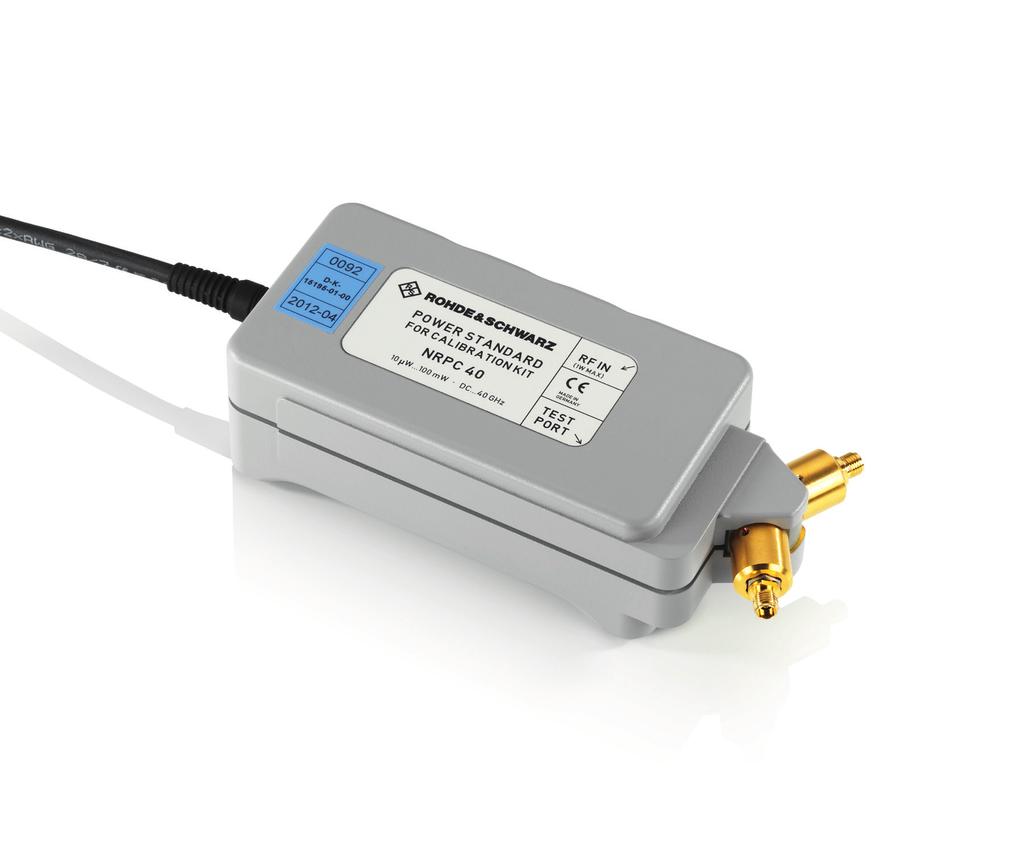
2 R&S NRPC Calibration Kits At a glance The four modular R&S NRPC calibration kits are used to calibrate power sensors of the R&S NRP, R&S FSH and R&S NRV families, as well as other makes, to a very high level of accuracy. Following calibration, the sensors are within the specified calibration uncertainties and usually remain below these uncertainties. Each calibration kit includes a highly accurate power standard that is traceable to primary power standards of the Physikalisch- Technische Bundesanstalt (PTB, Germany s national metrology institute) by means of a calibration certified by the Deutsche Akkreditierungsstelle (DAkkS, Germany s national accreditation body). In combination with a remote-controllable microwave generator, an R&S NRP/NRP2 power meter and the freeof-charge R&S Recal+ PC software, the calibration kits enable users to calibrate the power sensors of the R&S NRP, R&S FSH and R&S NRV 1) families as well as the voltage sensors of the R&S URV5 1) family in just a few minutes. Calibration also includes writing the updated calibration values to the sensor s data memory. Plug-ins for the R&S ZVA/R&S ZVB and R&S ZVK/R&S ZVM vector network analyzers are available for impedance calibration. The calibration uncertainty is determined individually for each power sensor, taking the relevant influence quantities into account. Four models are currently available: R&S NRPC18 for power sensors with N connector (DC to 18 GHz) R&S NRPC33 for power sensors with 3.5 mm connector (DC to 33 (26.5) GHz) R&S NRPC40 for power sensors with 2.92 mm connector (DC to 40 GHz) R&S NRPC50 for power sensors with 2.4 mm connector (DC to 50 GHz) The R&S NRPCxx-B1 option is used for regular verification of each R&S NRPC model. It consists of a thermal power sensor calibrated to the associated power standard and aligned such that it displays, for each frequency point, the same value as the power standard. Key facts Program-controlled calibration of the power sensors of the R&S NRP/R&S FSH/R&S NRV/R&S URV5 families Short measurement times for high throughput Modular concept for cost-effective, flexible operation DAkkS-certified, PTB-traceable 1) R&S NRVD base unit additionally required for these sensors. Calibration of an R&S NRP-Z55 thermal power sensor. 2
3 R&S NRPC Calibration Kits Benefits and key features High quality and reliability More than 25 years of experience in manufacturing power meters Superior to thermistor-based power standards Verification sensor for daily checking Exchangeable test port page 4 Precise and accurate Direct link to Germany s national metrology institute Gamma correction as an important prerequisite Dependable specifications page 6 Cost-efficient Flexible, modular concept High throughput page 8 Remote-control calibration R&S Recal+ user interface ZVX_Recal plug-in for integrating Rohde & Schwarz vector network analyzers No miscalibrations Integration into application programs page 9 Rohde & Schwarz R&S NRPC Calibration Kits 3

4 High quality and reliability Examples of R&S NRP power sensors. More than 25 years of experience in manufacturing power meters Calibration is a matter of trust, especially when using power meters, which are at the top of the calibration hierarchy, for high-frequency test and communications equipment. Rohde & Schwarz and its solid, innovative products have played a key role in shaping this market segment for many years. The company s location in Germany, its experienced development and production experts, and high manufacturing depth ensure that more and more users involved in R & D, production and service worldwide rely on power sensors from Rohde & Schwarz. The technologies developed for these sensors are also used in the R&S NRPC calibration kits power standards. Superior to thermistor-based power standards Especially when extremely high measurement accuracy is required, as is normally the case for power standards, a sensor type based on the antiquated thermistor technology is still being used today. The big advantage of inherent stability is offset by significant limitations that make it extremely difficult to work with these sensors. These limitations include poor impedance matching, long settling times in the seconds range and a small dynamic range. Thermoelectric transducer: used in all thermal power sensors and standards of the R&S NRP family The thermal sensors used in the R&S NRPC calibration kits power standards provide more accurate measurements and, at the same time, higher measurement speed, eliminating the disadvantages mentioned above. In addition, the new sensors feature the same high stability provided by thermistor-based sensors but are easier to verify, which is a further advantage. The key lies in the frequency range (up to DC) of the thermoelectric transducers used, an exclusive characteristic of all Rohde & Schwarz thermal power sensors. While the R&S NRVC calibration kit can be tested and readjusted by means of externally supplied DC voltages, the R&S NRPC calibration kits go a step further: The entire DC reference circuit has been integrated into the power standard. This allows a fully automatic test to be performed at any time in just a few seconds. Coplanar RF feeder Ground RF termination (1st heater) 2nd heater DC reference circuit for thermoelectric transducer Silicon membrane Thermopile (36 sections) P ref DC reference 2nd heater Silicon frame 2.0 mm P RF 1st heater Thermoelectric transducer + g Power sensor U out 4

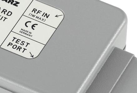
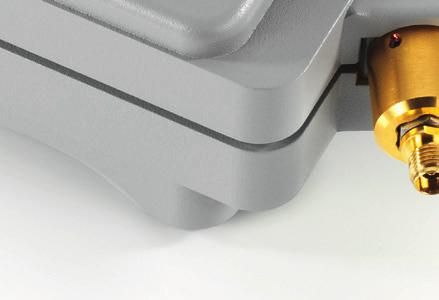
5 Verification sensor for daily checking One problem is unsolvable even for the integrated DC reference circuit: detecting a possible degradation of the integrated power splitter or the test port. This is why the R&S NRPCxx-B1 option is available. It provides a verification sensor that was pre-aligned to the associated power standard during manufacture and exhibits only negligibly small deviations from this standard at least as long as everything functions properly. With an impedance of 100 Ω, the verification sensor is extremely mismatched, which makes it possible to detect test port degradation whose only effect is a change in the test port s impedance matching. As a result, the sensor reacts much more sensitively to changes in the source matching than does a normal power sensor, allowing reliable detection of defects. Exchangeable test port The test port connector of all R&S NRPC calibration kits (except R&S NRPC18) can be easily replaced by the user, eliminating the need for immediate servicing if a power standard s test port is damaged. For this purpose, each calibration kit includes a second connector and corresponding calibration data for the power standard and the verification sensor. As a result, work can continue with unchanged accuracy after only a brief interruption. Equipment supplied with the R&S NRPC33/40/50, plus R&S NRPCxx-B1 option Verification sensor Microwave cable Power standard 20 db precision attenuator (with R&S NRPC33/40 only) Spare test port connector Torque wrench CD-ROM Rohde & Schwarz R&S NRPC Calibration Kits 5


6 Precise and accurate Direct link to Germany s national metrology institute The power standards stability that is ensured by the DC reference circuit and the verification sensor is an important prerequisite for reproducible, precise measurements. However, to provide a tool suitable for calibrating power sensors, stability needs to be combined with high absolute accuracy. High absolute accuracy means that the traceability to Germany s national metrology institute (PTB) is as direct as possible. For this reason, Rohde & Schwarz has set up a metrological infrastructure at its production site that allows integration of the transfer standards suitable for exchange with the PTB. Since these transfer standards are also part of the national primary standards, the highest possible level of accuracy is obtained. To keep the influence of random errors as low as possible already at the top of the calibration hierarchy, each frequency point is traced back to the primary standards via the weighted average of multiple transfer standards. Gamma correction as an important prerequisite Gamma correction is a synonym for a numeric compensation method that minimizes the mismatch uncertainties accompanying power transfers. As the term implies, the gamma correction method is based on the knowledge of the reflection coefficients of the test port and the DUT and compensates for the measurement errors caused by mul- Calibration hierarchy for Rohde & Schwarz power sensors and standards Thermistor-based, transfer standards Coaxial (N) and waveguide sizes National standard DAkkS-accredited calibration lab Reference standards NRP-Zxx thermocouple-based, coaxial transfer standards 1.85 mm 2.4 mm NRPC50 NRPC40 Company calibration lab Working or factory standards 2.92 mm Company inspection, test and measuring equipment 3.5 mm NRPC33 Product N NRPC18 6
7 tiple reflections. For power calibrations in the microwave range, gamma correction is mandatory, because impedance matching generally gets poorer as the frequency increases. This applies to the calibration of power sensors using the R&S NRPC calibration kits as well as to the calibration of the power standards. The difficult-to-measure, complex reflection coefficient of the test port plays a key role in gamma correction, since the uncertainty of this coefficient significantly determines the effect of the correction. Through in-house developments and by improving existing methods, Rohde & Schwarz has done pioneering work in this field. The residual mismatch uncertainty following gamma correction has become so small that it is practically negligible. Prior to the power calibration, the DUT s complex reflection coefficients must be determined with a vector network analyzer. If the R&S Recal+ PC software is used, this procedure can be integrated into power calibration. The user does not have to configure the vector network analyzer or reformat and upload the determined reflection coefficients. The vector network analyzers and calibration kits that are suitable for integration into R&S Recal+ are listed in the ordering information. Dependable specifications It is difficult to verify the accuracy of power standards, since their measurement uncertainties are in the order of those of the reference instruments. A reliable verification in this respect would require many comparisons with many different reference instruments. This is why the specifications do not state error limits but rather uncertainties for the results delivered by the power standard. Uncertainties are expectation values that are computed according to fixed rules and indicate the spread of measurement results. The computation takes into account stochastic influences such as measurement noise or the reproducibility of the plug connection, as well as systematic influences whose exact magnitude and sign are unknown. These include, in particular, measurement errors that persist after the correction of known influences due to insufficient knowledge of their exact value. For the power sensors of the R&S NRP/R&S FSH families and the R&S NRPC calibration kits, Rohde & Schwarz specifies exclusively the measurement uncertainty limits defined in the IEC/EN standard. Measurement uncertainty limits designate the greatest possible measurement uncertainties that are obtained by a computation according to the rules stated in the GUM 1) and assuming the most unfavorable conditions. The measurement uncertainties achieved in the individual case are usually considerably smaller. 1) Guide to the Expression of Uncertainty in Measurement (ISO/BIPM guideline). Measurement uncertainty caused by mismatch as a function of the reflection coefficients of the test port (Γ eq ) and of the DUT (Γ L ) Without gamma correction With gamma correction 10 % U 0.4 % U 5 % 0.2 % 0 % Г L Г eq 0 % Г L Г eq Rohde & Schwarz R&S NRPC Calibration Kits 7
8 Cost-efficient Flexible, modular concept Power measurement assemblies with the R&S NRPC calibration kit are set up quickly and, because they are compact, can be integrated into almost any work environment. Due to the modular concept, existing signal generators and power meters (R&S NRP/NRP2 and also R&S NRVD) can be used without having to settle for reduced accuracy or performance. This makes good economical sense especially when the power measurement assemblies set up with the R&S NRPC do not have to be constantly kept ready for operation. High throughput The R&S NRPC calibration kits perform calibration at unprecedented speed. The thermoelectric sensors used in the power standards need only a fraction of the time required by thermistor-based sensors. This is particularly advantageous when measurements have to be repeated or when multiple measurement paths must be calibrated. The R&S Recal+ PC software supports the measurementtime-optimized calibration of power sensors by means of sensor-specific measurement times and parallel measurements on the power standard and the DUT. For an R&S NRP-Z55 40 GHz thermal power sensor, a calibration of the absolute accuracy can be expected to take approx. 4 min. Such calibration includes three sweeps from 10 MHz to 40 GHz and subsequent averaging. For an R&S NRP-Z31 33 GHz three-path power sensor, the same procedure, including all three measurement paths, takes approx. 15 minutes. Achievable measurement times per frequency point for the R&S NRPC and for a thermistor-based power standard 10 Time in s 1 Thermistor-based power standard with state-of-the-art base unit NRPC 2-sigma noise content 0.1 % 0.2 % 0.5 % ± Power level in dbm 8

9 Remote-control calibration R&S Recal+ user interface In combination with a microwave generator, an R&S NRP/ NRP2 power meter and the free-of-charge R&S Recal+ PC software, the calibration kits enable users to calibrate the power sensors of the R&S NRP, R&S FSH and R&S NRV families in just a few minutes. The software s interactive user interface offers various standard functions for the measurements and for reading out, computing and writing calibration data to the sensor s data memory. Results can be displayed graphically or in table format. In addition, a complete input or output test report with a cover sheet and a list of measuring equipment can be printed out. The standard scope of functions also includes an archiving function and the possibility to output in plain text the calibration data saved for a sensor. All measuring instruments are controlled via IEC/IEEE bus. R&S Recal+ supports all components of the tried-andtested R&S NRVC power sensor calibration kit (DC to 18 GHz) for power sensors with N connectors. The R&S NRVC-B2 accessory set for linearity measurements will continue to be available until further notice. ZVX_Recal plug-in for integrating Rohde & Schwarz vector network analyzers This plug-in allows different Rohde & Schwarz vector network analyzers to be integrated into the power calibration. Suitable analyzers and associated calibration kits are listed in the ordering information. For users, the integrated reflection measurement has the great advantage that the vector network analyzer is configured and the determined reflection coefficients are uploaded in a suitable format by automatic control. The data can be used for gamma correction and for reporting purposes. No miscalibrations Calibration with R&S Recal+ gives users a certain degree of operating freedom but effectively prevents miscalibrations. All measurements are power-sensor-specifically configured, and critical process steps such as testing and readjusting the power standards via the DC reference circuit are completely inaccessible to the user. If gamma correction is required for a power calibration but the DUT s complex reflection coefficients are not available, it is not possible to generate new correction data from the calibration values. This applies to all power sensors with a frequency limit above 18 GHz. The amount of influence the user exerts on accuracy therefore depends on how much care is taken when screwing the DUT onto the power standard. This means that power sensors can also be calibrated by semi-skilled staff at no major risk. Integration into application programs The R&S NRPC calibration kits can, of course, also be remote-controlled via application programs, for example to calibrate power sensors from other manufacturers or to perform other measurement tasks. The physical connection can be made directly via the power standard s USB interface or via one of the R&S NRP/NRP2 remote-control interfaces (IEC/IEEE bus, Ethernet, USB). All parameters required for the measurements are stored in the power standard s data memory. These parameters include the calibration factors and the test port s equivalent reflection coefficients. For gamma correction, only the DUT s complex reflection coefficients for each frequency point need to be transferred to the power standard, which then performs the complete gamma correction automatically. User interface of the R&S Recal+ PC software with graphical display of the calibration result for an R&S NRP-Z56 50 GHz thermal power sensor. Rohde & Schwarz R&S NRPC Calibration Kits 9
10 Example The table below shows a simplified uncertainty budget for the calibration of an R&S NRP-Z56 power sensor with an R&S NRPC50 calibration kit at 1 mw (0 dbm). It comprises the major terms only, i.e. the calibration uncertainty of the R&S NRPC50 and the residual mismatch uncertainty M u after gamma correction. M u has been calculated with the following formula: M 2 2 U UΓ_ eq 2 2 Γ_ DUT = 200% 2 Γ + 2 Γ u eq DUT where Γ eq and Γ DUT denote the complex reflection coefficients of the test port and the DUT, whereas U Γ_eq and U Γ_DUT denote the expanded uncertainties of these coefficients (see footnote 1 on next page). Frequency range DUT reflection coefficient Uncertainty of Γ DUT Mismatch uncertainty (k = 2) Calibration uncertainty of R&S NRPC50 Total uncertainty (k = 2) Symbol Γ DUT U Γ_DUT M u DC to 100 MHz < % 0.7 % (0.030 db) 0.71 % (0.031 db) > 100 MHz to 2.4 GHz < % 1.0 % (0.042 db) 1.01 % (0.044 db) > 2.4 GHz to 8.0 GHz < % 1.1 % (0.049 db) 1.11 % (0.048 db) > 8.0 GHz to 12.4 GHz < % 1.3 % (0.057 db 1.31 % (0.057 db) > 12.4 GHz to 18.0 GHz < % 1.7 % (0.075 db) 1.82 % (0.079 db) > 18.0 GHz to 26.5 GHz < % 1.5 % (0.065 db) 1.57 % (0.068 db) > 26.5 GHz to 33.0 GHz < % 1.8 % (0.078 db) 1.91 % (0.083 db) > 33.0 GHz to 40.0 GHz < % 1.9 % (0.084 db) 2.12 % (0.092 db) > 40.0 GHz to 50.0 GHz < % 2.7 % (0.116 db) 2.81 % (0.122 db) 10
11 Specifications Power standards R&S NRPC18 R&S NRPC33 R&S NRPC40 R&S NRPC50 Frequency range DC to 18 GHz DC to 33 GHz DC to 40 GHz DC to 50 GHz Test port power range 10 µw to 100 mw ( 20 dbm to +20 dbm) Max. input power average/peak envelope 0.5 W (+27 dbm) continuous/40 W (+46 dbm) for max. 1 µs Test port connector N female 3.5 mm female 2.92 mm female 2.4 mm female Test port equivalent SWR (equivalent reflection coefficient Γ eq ) DC to 4.0 GHz > 4.0 GHz to 8.0 GHz > 8.0 GHz to 12.4 GHz > 12.4 GHz to 18.0 GHz > 18.0 GHz to 26.5 GHz > 26.5 GHz to 33.0 GHz > 33.0 GHz to 40.0 GHz > 40.0 GHz to 50.0 GHz Uncertainty of Γ 1) eq DC to 4.0 GHz > 4.0 GHz to 8.0 GHz > 8.0 GHz to 12.4 GHz > 12.4 GHz to 18.0 GHz > 18.0 GHz to 26.5 GHz > 26.5 GHz to 33.0 GHz > 33.0 GHz to 40.0 GHz > 40.0 GHz to 50.0 GHz < 1.06 (< 0.029) < 1.10 (< 0.048) < 1.10 (< 0.048) < 1.14 (< 0.065) < 1.35 (< 0.15) < 1.35 (< 0.15) < 1.50 (< 0.20) < 1.65 (< 0.25) < 1.35 (< 0.15) < 1.35 (< 0.15) < 1.50 (< 0.20) < 1.65 (< 0.25) < 1.65 (< 0.25) < 1.35 (< 0.15) < 1.35 (< 0.15) < 1.50 (< 0.20) < 1.65 (< 0.25) < 1.65 (< 0.25) < 1.65 (< 0.25) Zero offset after external zeroing 2) < 26 nw (15 nw (typ.)) < 28 nw (17 nw (typ.)) Zero drift 3) < 8 nw < 10 nw Measurement noise 4) < 26 nw (15 nw (typ.)) < 28 nw (17 nw (typ.)) Calibration factor 84 % 75 % 70 % 65 % Calibration uncertainty 5), 6) DC to 1 MHz > 1 MHz to < 10 MHz 10 MHz to 100 MHz > 100 MHz to 2.4 GHz > 2.4 GHz to 8.0 GHz > 8.0 GHz to 12.4 GHz > 12.4 GHz to 18.0 GHz > 18.0 GHz to 26.5 GHz > 26.5 GHz to 33.0 GHz > 33.0 GHz to 40.0 GHz > 40.0 GHz to 50.0 GHz 0.28 % (0.012 db) 0.33 % (0.014 db) 0.33 % (0.014 db) 0.50 % (0.022 db) 0.68 % (0.029 db) 0.84 % (0.036 db) 1.10 % (0.048 db) 0.7 % (0.029 db) 1.0 % (0.041 db) 1.1 % (0.048 db) 1.3 % (0.055 db) 1.7 % (0.074 db) 1.4 % (0.062 db) 1.7 % (0.075 db) Linearity 7) 0 C to +50 C 0.2 % (0.008 db) +23 C ±3.3 C 0.1 % (0.004 db) from 20 dbm to +10 dbm 0.7 % (0.029 db) 1.0 % (0.041 db) 1.1 % (0.048 db) 1.3 % (0.056 db) 1.7 % (0.075 db) 1.5 % (0.063 db) 1.7 % (0.075 db) 1.9 % (0.081 db) 0.7 % (0.030 db) 1.0 % (0.042 db) 1.1 % (0.049 db) 1.3 % (0.057 db) 1.7 % (0.075 db) 1.5 % (0.065 db) 1.8 % (0.078 db) 1.9 % (0.084 db) 2.7 % (0.116 db) 1) Denotes the estimated magnitude of the complex-valued difference between the equivalent test port reflection coefficient and its calibrated value (expressed with a coverage factor of two). Uncertainties of reflection coefficients need to be known for the calculation of the residual mismatch uncertainty after vector-corrected power calibration (gamma correction). The uncertainties given for the test port equivalent reflection coefficient are valid only after calibration at Rohde & Schwarz. 2) Specifications expressed as an expanded uncertainty with a confidence level of 95 % (two standard deviations). For calculating zero offsets at higher confidence levels, use the properties of the normal distribution (e.g % confidence level for three standard deviations). 3) Within one hour after zeroing, permissible temperature change ±1 C, following a two-hour warm-up of the power standard. 4) Two standard deviations at s integration time in continuous average mode, with aperture time set to default value. The integration time is defined as the total time used for signal acquisition, i.e. the product of twice the aperture time and the averaging number. Multiplying the noise specifications by (10.24 s/integration time) yields the noise contribution at other integration times. 5) Limits of expanded uncertainty (k = 2) for the results delivered by the power standard for measurements performed at the calibration level (0 dbm) within a temperature range of +23 C ±3.3 C and at the calibration frequencies, referenced to the output power available on a perfectly matched load, within one year after calibration. Specifications include uncertainty of calibration, stability over time, temperature effect, zero offset and measurement noise (up to a 2σ value of db). 6) Calibration frequencies: DC; from 10 MHz to 100 MHz in 10 MHz steps; from 250 MHz to the upper frequency limit in 250 MHz step. The power standard of R&S NRPC18 is calibrated at additional frequencies: 9 khz, 14 khz, 20 khz, 30 khz, 50 khz, 100 khz, 200 khz, 500 khz, 1 MHz, 2 MHz, 5 MHz. 7) Limits of expanded uncertainty (k = 2) for relative power measurements referenced to the calibration level (0 dbm), excluding zero offset, zero drift and measurement noise. Rohde & Schwarz R&S NRPC Calibration Kits 11
12 Power standard with test port power attenuated by 20 db 8) R&S NRPC18 R&S NRPC33 R&S NRPC40 Frequency range DC to 18 GHz DC to 26.5 GHz DC to 40 GHz Test port power range 40 dbm to 0 dbm Test port connector N female 3.5 mm female 2.92 mm female Test port equivalent SWR (equivalent reflection coefficient Γ eq ) DC to 4.0 GHz > 4.0 GHz to 8 GHz 8 GHz to 18 GHz 18 GHz to 26.5 GHz > 26.5 GHz to 40.0 GHz Uncertainty of Γ 1) eq DC to 8.0 GHz > 8.0 GHz to 12.4 GHz > 12.4 GHz to 18 GHz 18 GHz to 26.5 GHz > 26.5 GHz to 40.0 GHz Calibration uncertainty 5) DC to 1 MHz > 1 MHz to < 10 MHz 10 MHz to 100 MHz > 100 MHz to 2.4 GHz > 2.4 GHz to 4 GHz > 4.0 GHz to 8.0 GHz > 8.0 GHz to 12.4 GHz > 12.4 GHz to 18.0 GHz > 18.0 GHz to 26.5 GHz > 26.5 GHz to 33.0 GHz > 33.0 GHz to 40.0 GHz < 1.06 (< 0.03) < 1.06 (< 0.03) < 1.11 (< 0.05) % (0.023 db) 0.57 % (0.025 db) 0.57 % (0.025 db) 0.68 % (0.029 db) 0.81 % (0.035 db) 0.94 % (0.041 db) 1.30 % (0.056 db) 1.46 % (0.063 db) < 1.11 (< 0.05) % (0.031 db) 1.0 % (0.043 db) 1.2 % (0.050 db) 1.2 % (0.050 db) 1.3 % (0.058 db) 1.8 % (0.077 db) 1.5 % (0.065 db) < 1.11 (< 0.05) < 1.35 (< 0.15) % (0.031 db) 1.0 % (0.043 db) 1.1 % (0.050 db) 1.1 % (0.050 db) 1.4 % (0.059 db) 1.8 % (0.078 db) 1.5 % (0.066 db) 1.8 % (0.078 db) 1.9 % (0.083 db) 8) Using the precision attenuator supplied with the R&S NRPC18, R&S NRPC33 and R&S NRPC40. Verification sensors R&S NRPC18-B1 R&S NRPC33-B1 R&S NRPC40-B1 R&S NRPC50-B1 Frequency range DC to 18 GHz DC to 33 GHz DC to 40 GHz DC to 50 GHz Power measurement 1 µw to 100 mw ( 30 dbm to +20 dbm) range Max. input power average/peak envelope 0.2 W (+23 dbm) continuous/5 W (+37 dbm) for max. 1 µs Test port connector N male 3.5 mm male 2.92 mm male 2.4 mm male Impedance matching (SWR) < 3 (< 2 (typ.)) Calibration not specified; sensors are calibrated and aligned to associated power standard uncertainty Additional characteristics Sensor type power standard thermoelectric power sensor combined with a resistive power splitter in a power leveling setup verification sensors thermoelectric power sensor Measurand power standard power of wave emanating from test port 9) verification sensors power of incident wave Insertion loss (power standards only) between signal input and test port 6 db nominal at DC over entire frequency range of power standard; including microwave cable R&S NRPC18 < 9.0 db (< 8.0 db (typ.)) R&S NRPC33 < 10.9 db (< 10.0 db (typ.)) R&S NRPC40 < 11.6 db (< 10.5 db (typ.)) R&S NRPC50 < 12.3 db (< 11.0 db (typ.)) Measurement function stationary and recurring waveforms continuous average Continuous average function measurand mean power over recurring acquisition interval aperture 1 ms to 300 ms (5 ms default) window function uniform or von Hann 10) duty cycle correction 11) % to % measurement buffer capacity 12) 1 to 1024 results 12
13 Additional characteristics Averaging filter modes auto off (fixed averaging number) auto on (continuously auto-adapted) auto once (automatically fixed once) auto off averaging number 2 N ; N = 0 to 16 auto on/once operating mode: normal averaging number adapted to resolution setting and power to be measured operating mode: fixed noise averaging number adapted to specified noise content result output mode: moving continuous, independent of averaging number rate can be limited to 0.1 s 1 mode: repeat final result only Attenuation correction function corrects the measurement result by means of a fixed factor (db offset) range db to db Embedding (power standards only) function incorporates a two-port device at the RF output so that the measurement plane is shifted to the output of this device parameters S 11, S 21, S 12 and S 22 of device frequencies 1 to 1000 Gamma correction (power standards only) function removes the influence of impedance mismatch from the measurement result so that the power of the wave emanating at the test port can be read more accurately parameters magnitude and phase of reflection coefficient of DUT Frequency response correction function removes the influence of frequency response for the sensor section and the power splitter parameter center frequency of test signal residual uncertainty see calibration uncertainty specifications Measurement time 13) 2 N : averaging number 2 (aperture µs) 2 N + 4 ms + t d t d must be taken into account when auto delay 14) is active. t d equals 40 ms with R&S NRPC33/40/50 and 80 ms with R&S NRPC18 10 s Zeroing (duration) Temperature effect 15) DC to 100 MHz < 0.05 %/K (< db/k) 100 MHz to 50 GHz < 0.10 %/K (< db/k) Precision termination (part of R&S NRPC18) frequency range SWR max. input power RF connector for calibration of R&S URV5-Z2/-Z4 voltage sensors DC to 3 GHz < 1.02 (< 1.01 (typ.)) 1 W (+30 dbm) N male 9) Gamma correction can be applied to reduce mismatch uncertainty. 10) Preferably used with determined modulation when the aperture time cannot be matched to the modulation period. Compared with a uniform window, measurement noise is about 22 % higher. 11) For measuring the power of periodic bursts based on an average power measurement. 12) To increase measurement speed, the power standard can be operated in buffered mode. In this mode, measurement results are stored in a buffer of user-definable size and then output as a block of data when the buffer is full. To enhance measurement speed even further, the power standard and the verification set can be set to record the entire series of measurements when triggered by a single event. In this case, the power standard and the verification set automatically start a new measurement as soon as the previous measurement is completed. 13) Valid for repeat mode, extending from the beginning to the end of all transfers via the USB interface of the power standard. Measurement times under remote control of the R&S NRP2 base unit via IEC/IEEE bus are approximately 2.5 ms longer, extending from the start of the measurement up to when the measurement result has been supplied to the output buffer of the R&S NRP2. 14) With activated auto delay, the beginning of a measurement sequence is delayed so that settled readings are obtained even if the measurement command (remote trigger) coincides with a signal step up to ±10 db. 15) Error of the measurement result with respect to temperature. Rohde & Schwarz R&S NRPC Calibration Kits 13
14 General data Environmental conditions Temperature operating temperature range 0 C to +50 C permissible temperature range 10 C to +55 C storage temperature range 40 C to +70 C Damp heat +25 C/+40 C, 95 % relative humidity, cyclic, in line with EN with restriction: non-condensing Mechanical resistance Vibration sinusoidal 5 Hz to 55 Hz, 0.15 mm amplitude constant, 55 Hz to 150 Hz, 0.5 g constant, in line with EN random 10 Hz to 300 Hz, acceleration 1.2 g (RMS), in line with EN Shock 40 g shock spectrum, in line with MIL-STD-810E, method 516.4, procedure I Product conformity Electromagnetic compatibility EU: in line with EMC Directive 2004/108/EC applied harmonized standards: EN (industrial environment) EN EN (class B) Safety in line with EN Calibration interval 1 year Dimensions and weight Dimensions (W H D) case 467 mm 242 mm 84 mm (18.39 in 9.53 in 3.31 in) power standard of R&S NRPC18 67 mm 47 mm 245 mm (2.64 in 1.85 in 9.65 in) power standard of R&S NRPC33/40/50 67 mm 47 mm 192 mm (2.64 in 1.85 in 7.56 in) verification sensor 48 mm 31 mm 155 mm (1.89 in 1.22 in 6.10 in) length (D) including connecting cable power standard 1.70 m (67 in) verification sensor 1.62 m (64 in) Weight case of R&S NRPC18, fully equipped 4.2 kg (9.3 lb) case of R&S NRPC33/40/50, fully equipped 3.5 kg (7.7 lb) power standard of R&S NRPC kg (4.1 lb) power standard of R&S NRPC33/40/ kg (3.1 lb) verification sensor 0.26 kg (0.57 lb) Product contents R&S NRPC18 power standard, precision attenuator, precision termination, microwave cable, adapter cable for R&S FSH-Z1/-Z18 power sensors, N (male) to BNC (male) adapter, CD-ROM R&S NRPC33/40/50 power standard, precision attenuator (not with R&S NRPC50), microwave cable, spare test port connector, torque wrench, adapter from N (male) to connector type (female) of the specific calibration kit, CD-ROM Your local Rohde & Schwarz expert will help you determine the optimum solution for your requirements. To find your nearest Rohde & Schwarz representative, visit 14
15 Ordering information Designation Type Order No. Power sensor calibration kits + options Calibration Kit, N, DC to 18 GHz, 0.1 µw to 100 mw R&S NRPC Verification Kit for R&S NRPC18 R&S NRPC18-B Calibration Kit, 3.5 mm, DC to 33 GHz, 0.1 µw to 100 mw R&S NRPC Verification Kit for R&S NRPC33 R&S NRPC33-B Calibration Kit, 2.92 mm, DC to 40 GHz, 0.1 µw to 100 mw R&S NRPC Verification Kit for R&S NRPC40 R&S NRPC40-B Calibration Kit, 2.4 mm, DC to 50 GHz, 10 µw to 100 mw R&S NRPC Verification Kit for R&S NRPC50 R&S NRPC50-B Accessory Set for linearity measurements, 100 khz to 50 MHz, 0.5 µw to 2 W R&S NRVC-B (R&S NRVD base unit and suitable signal generator required) Power meter base units + mandatory options Power Meter R&S NRP Second Sensor Input (B) R&S NRP-B Dual-Channel Power Meter R&S NRVD Signal generators + mandatory options Signal Generator (base unit) R&S NRPC18 R&S SMA100A (up to 6 GHz only) + Frequency Range 9 khz to 6 GHz with step attenuator R&S SMA-B RF and Microwave Signal Generator (base unit) R&S NRPC18 R&S SMB100A (up to 6 GHz only) + Frequency Range 9 khz to 6 GHz R&S SMB-B RF and Microwave Signal Generator (base unit) R&S NRPC18 R&S SMB100A Frequency Range 100 khz to 20 GHz with step attenuator R&S SMB-B High Power Option for R&S SMB-B120 R&S SMB-B Signal Generator (base unit) R&S NRPC33/ R&S SMB100A NRPC40 + Frequency Range 100 khz to 40 GHz with step attenuator R&S SMB-B High Power Option for R&S SMB-B140 R&S SMB-B Vector network analyzers + mandatory options Vector Network Analyzer, 20 GHz, 2 ports R&S NRPC18 R&S ZVB Calibration Kit, N type, 0 Hz to 18 GHz R&S ZV-Z Vector Network Analyzer, 24 GHz, 2 ports R&S NRPC18 R&S ZVA Calibration Kit, N type, 0 Hz to 18 GHz R&S ZV-Z Vector Network Analyzer, 40 GHz, 2 ports R&S NRPC33 R&S ZVA Calibration Kit, 3.5 mm, 0 Hz to 33 GHz R&S ZV-Z235E Vector Network Analyzer, 40 GHz, 2 ports R&S NRPC40 R&S ZVA Calibration Kit, 2.92 mm, 0 Hz to 40 GHz R&S ZV-Z Vector Network Analyzer, 50 GHz, 2 ports R&S NRPC50 R&S ZVA Calibration Kit, 2.4 mm, 0 Hz to 50 GHz R&S ZV-Z Service options Extended Warranty, one year R&S WE1NRPC Please contact your local Rohde & Schwarz Extended Warranty, two years R&S WE2NRPC sales office. Extended Warranty, three years R&S WE3NRPC Extended Warranty, four years R&S WE4NRPC Extended Warranty with Calibration Coverage, one year R&S CW1NRPC Extended Warranty with Calibration Coverage, two years R&S CW2NRPC Extended Warranty with Calibration Coverage, three years R&S CW3NRPC Extended Warranty with Calibration Coverage, four years R&S CW4NRPC Rohde & Schwarz R&S NRPC Calibration Kits 15
16 Service you can rely on Worldwide Local and personalized Customized and flexible Uncompromising quality Long-term dependability About Rohde & Schwarz Rohde & Schwarz is an independent group of companies specializing in electronics. It is a leading supplier of solutions in the fields of test and measurement, broadcasting, radiomonitoring and radiolocation, as well as secure communications. Established more than 75 years ago, Rohde & Schwarz has a global presence and a dedicated service network in over 70 countries. Company headquarters are in Munich, Germany. Environmental commitment Energy-efficient products Continuous improvement in environmental sustainability ISO certified environmental management system Certified Quality System ISO 9001 Rohde & Schwarz GmbH & Co. KG Regional contact Europe, Africa, Middle East customersupport@rohde-schwarz.com North America TEST RSA ( ) customer.support@rsa.rohde-schwarz.com Latin America customersupport.la@rohde-schwarz.com Asia/Pacific customersupport.asia@rohde-schwarz.com China / customersupport.china@rohde-schwarz.com R&S is a registered trademark of Rohde & Schwarz GmbH & Co. KG Trade names are trademarks of the owners Printed in Germany (sk) PD Version May 2013 R&S NRPC Data without tolerance limits is not binding Subject to change Rohde & Schwarz GmbH & Co. KG München, Germany
R&S NRPC Calibration Kits Calibration of power sensors
 R&S NRPC Calibration Kits Calibration of power sensors Product Brochure Version 03.00 year NRPC_bro_en_5214-6297-12_v0300.indd 1 10.04.2018 10:30:29 R&S NRPC Calibration Kits At a glance The five modular
R&S ZVT Vector Network Analyzer Specifications
 R&S ZVT Vector Network Analyzer Specifications Test & Measurement Data Sheet 08.00 CONTENTS Definitions... 3 Specifications... 4 Measurement range...4 Measurement speed...5 Measurement accuracy...6 Effective
R&S ZNC Vector Network Analyzer Specifications
 ZNC3_dat-sw_en_5214-5610-22_v0300_cover.indd 1 Data Sheet 03.00 Test & Measurement R&S ZNC Vector Network Analyzer Specifications 04.09.2012 13:39:47 CONTENTS Definitions... 3 Measurement range... 4 Measurement
R&S ZNB Vector Network Analyzer Specifications
 Umschlag_ZNB4-8_dat-sw_en_5214-5384-22.indd 1 Data Sheet 02.00 Test & Measurement R&S ZNB Vector Network Analyzer Specifications 07.11.2011 10:03:35 CONTENTS Definitions... 3 Measurement range... 4 Measurement
R&S RSC Step Attenuator Specifications
 R&S RSC Step Attenuator Specifications Data Sheet Version 05.00 CONTENTS Definitions... 3 Specifications... 4 Step attenuator, 139 db, 1 db steps, DC to 6 GHz (models.03 and.13)... 4 Step attenuator, 139.9
R&S ZV-Z5x Calibration Units Specifications
 R&S ZV-Z5x Calibration Units Specifications Test & Measurement Data Sheet 10.00 Specifications apply under the following conditions: Sufficient warm-up time (approx. 15 minutes) at ambient temperature,
Voltage Sensors URV5-Z
 Data sheet Version 05.00 Voltage Sensors URV5-Z May 2005 Universal voltage measurements from RF to microwaves The voltage sensors of the URV5-Z series are indispensable tools in RF and microwave laboratories,
R&S ZV-Z3xx T-Checker Specifications
 ZV-Z3xx_dat-sw_en_3607-0575-22_cover.indd 1 Data Sheet 01.00 Test & Measurement R&S ZV-Z3xx T-Checker Specifications 17.06.2014 15:14:20 CONTENTS Definitions... 3 Specifications... 4 Measurement range...
R&S ZNBT8 Vector Network Analyzer Specifications
 E stablished 1981 Advanced Test Equipment Rentals www.atecorp.com 800-404-ATEC (2832) ZNBT8_dat-sw_en_3606-9727-22_v0200_cover.indd 1 Data Sheet 02.00 Test & Measurement R&S ZNBT8 Vector Network Analyzer
R&S ZN-Z5x Calibration Units Specifications. Data Sheet V03.00
 R&S ZN-Z5x Calibration Units Specifications Data Sheet V03.00 CONTENTS Definitions... 4 Specifications... 6 Model description R&S ZN-Z5x... 6 Model description R&S ZN-Z15x... 7 Input power limits... 7
R&S ZVT Vector Network Analyzer Specifications
 ZVT_dat-sw_en_0758-065-22_v0900_cover.indd Data Sheet 09.00 Test & Measurement R&S ZVT Vector Network Analyzer Specifications 06.03.205 5:50:4 CONTENTS Definitions... 3 Specifications... 4 Measurement
R&S ZN-Zxxx Calibration Units Specifications. Data Sheet V04.00
 R&S ZN-Zxxx Calibration Units Specifications Data Sheet V04.00 Version 03.00, January 2019 CONTENTS Definitions... 4 Specifications... 6 Model description R&S ZN-Z5x... 6 Model description R&S ZN-Z15x...
R&S ZV-Z5x Calibration Units Specifications
 R&S ZV-Z5x Calibration Units Specifications Test & Measurement Data Sheet 09.01 Specifications apply under the following conditions: Sufficient warm-up time (approx. 15 minutes) at ambient temperature,
R&S NRP-Zxx Power Sensors Specifications
 R&S NRP-Zxx Power Sensors Specifications year Data Sheet Version 11.00 CONTENTS Definitions... 3 Overview of the R&S NRP-Zxx power sensors... 4 Specifications in brief of the R&S NRP-Zxx power sensors...
R&S FU129 Antenna Filter Unit Antenna switching, rotator control and signal attenuation, amplification and filtering
 Radiomonitoring & Radiolocation Product Brochure 02.01 R&S FU129 Antenna Filter Unit Antenna switching, rotator control and signal attenuation, amplification and filtering R&S FU129 Antenna Filter Unit
R&S ZV-Z135 Calibration Kit Specifications
 R&S ZV-Z135 Calibration Kit Specifications Test & Measurement Data Sheet 01.01 CONTENTS Definitions... 3 Specifications... 4 Mechanical data... 4 Electrical data of R&S ZV-Z135 (3.5 mm, female)... 4 Electrical
R&S NRP USB and LAN Power Sensors Specifications
 NRP-Family_dat-sw_en_3607-0852-22_v0200_Cover.indd 1 Data Sheet 02.00 Test & Measurement R&S NRP USB and LAN Power Sensors Specifications 01.12.2015 13:55:03 CONTENTS Definitions... 3 Overview of the R&S
R&S NRP USB and LAN Power Sensors Specifications
 R&S NRP USB and LAN Power Sensors Specifications year warranty Test & Measurement Data Sheet 03.00 CONTENTS Definitions... 3 Overview of the R&S NRP power sensors... 4 Specifications in brief of the R&S
R&S NRP USB and LAN Power Sensors Specifications
 R&S NRP USB and LAN Power Sensors Specifications year Test & Measurement Data Sheet 04.00 CONTENTS Definitions... 3 Overview of the R&S NRP power sensors... 4 Specifications in brief of the R&S NRP power
R&S NRPM Over-the-Air (OTA) Power Measurement Solution For 5G, WLAN IEEE ad and IEEE ay
 Power Measurement Solution For 5G, WLAN IEEE ad and IEEE ay") year Product Brochure Version 0.00 R&S NRPM Over-the-Air (OTA) Power Measurement Solution For 5G, WLAN IEEE 80.ad and IEEE 80.ay NRPM_bro_en_607-4687-_v000.indd 8.0.09 5:59:08 R&S NRPM Over-the-Air (OTA)
year Product Brochure Version 0.00 R&S NRPM Over-the-Air (OTA) Power Measurement Solution For 5G, WLAN IEEE 80.ad and IEEE 80.ay NRPM_bro_en_607-4687-_v000.indd 8.0.09 5:59:08 R&S NRPM Over-the-Air (OTA)
Technical Information
 Technical Information Power Sensors R&S NRP-Z51, -Z55 Thermoelectric accuracy at its best The new power sensors for the frequency ranges DC to 18 GHz (R&S NRP-Z51) and DC to 40 GHz (R&S NRP-Z55) for the
Vector Network Analyzers ZVB
 Specifications Version 05.00 Vector Network Analyzers ZVB September 2005 Specifications MEASUREMENT RANGE...3 MEASUREMENT SPEED...5 MEASUREMENT ACCURACY...6 EFFECTIVE SYSTEM DATA...8 TEST PORT OUTPUT...8
R&S ZVA-Zxx Millimeter-Wave Converters Network analysis up to 500 GHz
 ZVA-Zxx_bro_en_5214-2033-12.indd 1 Product Brochure 06.02 Test & Measurement R&S ZVA-Zxx Millimeter-Wave Converters Network analysis up to 500 GHz 28.10.2014 21:05:04 R&S ZVA-Zxx Millimeter-Wave Converters
R&S FSC Spectrum Analyzer Specifications
 R&S FSC Spectrum Analyzer Specifications year Data Sheet Version 03.00 CONTENTS Base unit... 3 Frequency... 3 Sweep time... 3 Bandwidths... 3 Level... 4 Trigger functions... 5 Tracking generator (model.13/.16
R&S NRP Power Meter Family Specifications
 R&S NRP Power Meter Family Specifications year Data Sheet Version 06.00 CONTENTS Definitions... 3 Overview of the R&S NRP power sensors... 4 Specifications in brief of the R&S NRP power sensors... 5 Multipath
R&S EB500 Monitoring Receiver Specifications
 Radiomonitoring & Radiolocation Data Sheet 01.02 R&S EB500 Monitoring Receiver Specifications CONTENTS Definitions... 3 Specifications... 4 Frequency...4 Linearity...4 Interference rejection...4 Noise
Technical Information
 Technical Information Power Sensor R&S NRP-Z91 Universal power measurement from 9 khz to 6 GHz The Power Sensor R&S NRP-Z91 is designed for measuring average power in a very wide frequency range. In particular,
Noise Figure Measurement Applications Specifications
 Noise Figure Measurement Applications Specifications R&S FSW-K30 R&S FSWP-K30 R&S FPS-K30 R&S FSV-K30 R&S FPL1-K30 Data Sheet Version 02.02 CONTENTS Definitions... 3 Specifications... 4 Frequency... 4
Thermal Power Sensor
 Test and Measurement Division Manual Thermal Power Sensor R&S NRP-Z51 DC to 18 GHz / 1 µw to 100 mw 1138.0005.02 R&S NRP-Z55 DC to 40 GHz / 1 µw to 100 mw 1138.2008.02 Printed in the Federal Republic of
Power Added Efficiency Measurement with R&S ZNB/ R&S ZVA
 Power Added Efficiency Measurement with R&S ZNB/ R&S ZVA Application Note Products: R&S ZNB R&S ZVA Power Added Efficiency (PAE) is a key parameter for the characterization of an amplifier. This application
R&S FS-K112PC NFC Measurement Software Specifications
 FS_K112-PC_dat-sw_3606-7047-22_cover.indd 1 Data Sheet 03.00 Test & Measurement R&S FS-K112PC NFC Measurement Software Specifications 06.10.2014 18:19:15 CONTENTS Definitions... 3 Specifications... 4 Minimum
R&S FSH4/8 Spectrum Analyzer Specifications
 R&S FSH4/8 Spectrum Analyzer Specifications Test & Measurement Data Sheet 02.00 CONTENTS Specifications... 3 Frequency...3 Sweep time...3 Bandwidths...4 Level...4 Trigger functions...5 Inputs and outputs...6
Power Meter NRVS. Power, level and voltage measurements from DC to 40 GHz
 Power Meter NRVS Power, level and voltage measurements from DC to 40 GHz Accurate, general-purpose, easy-to-use Intelligent measuring heads: just plug them in and measure DC frequency input for tracking
R&S CBT/R&S CBT32 Bluetooth Tester Specifications
 Established 1981 Advanced Test Equipment Rentals www.atecorp.com 800-404-ATEC (2832) R&S CBT/R&S CBT32 Bluetooth Tester Specifications Test & Measurement Data Sheet 06.00 CONTENTS Unit specifications...
R&S SMC100A Signal Generator Specifications
 R&S SMC100A Signal Generator Specifications Test & Measurement Data Sheet 01.00 CONTENTS Key features... 3 Specifications... 4 RF characteristics...4 Frequency...4 Frequency sweep...4 Reference frequency...4
Attenuators and Matching Pads, Terminations 75 mw to 1000 W, DC to 18 GHz
 Product Brochure Version 8. Attenuators and Matching Pads, Terminations 75 mw to W, DC to 8 GHz Attenuators_dat-bunt_en_758-96_3_v8.indd 3.3.7 7:33:39 Attenuators As a rule, the reflection coefficient
R&S ENV216 Two-Line V-Network For disturbance voltage measurements on single-phase EUTs
 R&S ENV216 Two-Line V-Network For disturbance voltage measurements on single-phase EUTs Test & Measurement Data Sheet 03.00 R&S ENV216 Two-Line V-Network At a glance The R&S ENV216 two-line V-network meets
Analog Modulation Analysis (AM/FM/φM) Specifications
 Specifications") Analog Modulation Analysis (AM/FM/φM) Specifications R&S FSW-K7 R&S ESW-K7 R&S FSWP-K7 R&S FSV-K7 R&S FSL-K7 R&S FPS-K7 R&S FPL1-K7 R&S VSE-K7 Data Sheet Version 06.00 CONTENTS Definitions... 3 Specifications...
Analog Modulation Analysis (AM/FM/φM) Specifications R&S FSW-K7 R&S ESW-K7 R&S FSWP-K7 R&S FSV-K7 R&S FSL-K7 R&S FPS-K7 R&S FPL1-K7 R&S VSE-K7 Data Sheet Version 06.00 CONTENTS Definitions... 3 Specifications...
R&S ESCI/ESCI7 EMI Test Receiver Specifications
 R&S ESCI/ESCI7 EMI Test Receiver Specifications Test & Measurement Data Sheet 03.00 Specifications Specifications apply under the following conditions: 15 minutes warm-up time at ambient temperature, specified
Complimentary Reference Material
 Complimentary Reference Material This PDF has been made available as a complimentary service for you to assist in evaluating this model for your testing requirements. TMG offers a wide range of test equipment
R&S TS8997 Regulatory Test System for Wireless Devices
 R&S TS8997 Regulatory Test System for Wireless Devices Product Brochure Version 03.01 ETSI EN 300328 V1.8.1/ETSI EN 301893 V1.7.1 compliance tests in the 2.4/5 GHz band TS8997_bro_en_3606-8095-12_v0301.indd
R&S ZVL Vector Network Analyzer Specifications
 R&S ZVL Vector Network Analyzer Specifications Data Sheet Version 10.00 CONTENTS Definitions... 3 Specifications... 4 Measurement range... 4 Measurement speed... 4 Measurement accuracy... 5 Effective system
Power Sensors NRV-Z. For RF and microwave power measurements
 Data sheet Version 04.01 Power Sensors NRV-Z October 2004 For RF and microwave power measurements Thermal sensors and diode sensors for high-precision power measurements Compatible with NRVS, NRVD, URV35
R&S ZNA Vector Network Analyzer Specifications
 R&S ZNA Vector Network Analyzer Specifications Data Sheet Version 01.02 year ZNA_dat-sw_en_5215-4652-22_v0102_cover.indd 1 07.01.2019 12:23:03 Version 01.02 January 2019 CONTENTS Definitions... 3 Measurement
Spectrum Analyzer FSL
 Specifications Version 02.00 Spectrum Analyzer FSL August 2005 Specifications Specifications Specifications apply under the following conditions: 15 minutes warm-up time at ambient temperature, specified
Measuring Receiver FSMR
 Product brochure Version 01.00 02.00 Measuring Receiver FSMR November April 2004 2006 All-in-one solution for the calibration of signal generators and attenuators Frequency range from 20 Hz to 3/26.5/50
PXIe Contents. Required Software CALIBRATION PROCEDURE
 CALIBRATION PROCEDURE PXIe-5160 This document contains the verification and adjustment procedures for the PXIe-5160. Refer to ni.com/calibration for more information about calibration solutions. Contents
R&S FSV Signal and Spectrum Analyzer Specifications
 R&S FSV Signal and Spectrum Analyzer Specifications Test & Measurement Data Sheet 02.02 CONTENTS Specifications... 3 Frequency...3 Sweep time...4 Resolution bandwidths...4 Level...5 Measurement speed...8
R&S CMU-Z10/-Z11 Antenna Coupler/ RF Shielding Cover Simple interference-free testing of all mobiles
 R&S CMU-Z1/-Z11 Antenna Coupler/ RF Shielding Cover Simple interference-free testing of all mobiles Test & Measurement Data Sheet 3. R&S CMU-Z1 /-Z11/-Z1/-Z13/-Z1 At a glance Anyone engaged in mobile phone
R&S ZVH Cable and Antenna Analyzer Specifications
 Umschlag_ZVH_dat-sw_v0300.indd 1 Data Sheet 03.00 Test & Measurement R&S ZVH Cable and Antenna Analyzer Specifications 18.05.2011 11:30:50 CONTENTS Definitions... 3 Specifications of the R&S ZVH cable
MA24104A. Inline High Power Sensor. True-RMS, 600 MHz to 4 GHz
 Product Brochure MA24104A Inline High Power Sensor True-RMS, 600 MHz to 4 GHz A Standalone, Compact, and Highly Accurate Inline High Power Sensor for your RF Power Measurement Needs MA24104A at a Glance
Guide Version Five techniques for fast, accurate power integrity measurements
 Guide Version 01.00 Five techniques for fast, accurate power integrity measurements Rail voltages are getting smaller, and tolerances are decreasing. As a result, making accurate power rail measurements
Spectrum Analyzer R&S FS300
 Spectrum Analyzer R&S FS300 9 khz to 3 GHz The new product family from Rohde & Schwarz Professional test equipment for laboratory, service and production The R&S FS300 is a highly accurate spectrum analyzer
R&S FSV Signal Analyzer Specifications
 R&S FSV Signal Analyzer Specifications Test & Measurement Data Sheet 01.00 CONTENTS Specifications... 3 Frequency...3 Sweep time...4 Resolution bandwidths...4 Level...5 Measurement speed...7 Trigger functions...8
Data Sheet Version R&S RT-ZVCxx Multi-Channel Power Probe Specifications
 Data Sheet Version 05.01 R&S RT-ZVCxx Multi-Channel Power Probe Specifications CONTENTS Definitions... 3 Probe characteristics... 4 Voltmeter of the R&S RT-ZVC02/02A/04/04A... 4 Amperemeter of the R&S
R&S NRT Power Reflection Meter Family R&S NRT2 and R&S NRT-Zxx
 R&S NRT Power Reflection Meter Family R&S NRT2 and R&S NRT-Zxx Product Brochure Version 01.00 year NRT_bro_en_5215-0986-12_v0100.indd 1 07.08.2017 10:45:57 R&S NRT Power Reflection Meter Family At a glance
R&S FSWP Phase Noise Analyzer Specifications
 R&S FSWP Phase Noise Analyzer Specifications Test & Measurement Data Sheet 02.01 CONTENTS Definitions... 3 Specifications... 4 Frequency... 4 Phase noise measurements... 4 Phase noise sensitivity with
R&S FSWP Phase Noise Analyzer Specifications
 FSWP_dat-sw_en_3607-2090-22_v0300_cover.indd 1 Data Sheet 03.00 Test & Measurement R&S FSWP Phase Noise Analyzer Specifications 19.05.2016 10:13:04 CONTENTS Definitions... 3 Specifications... 4 Frequency...
Signal Generator SMA 100A
 Specifications Version 01.01 Signal Generator SMA 100A April 2006 Specifications CONTENTS CONTENTS... 2 KEY FEATURES... 3 SPECIFICATIONS... 4 RF CHARACTERISTICS... 4 Frequency... 4 Frequency sweep... 4
Signal Generator SMA100A
 Product brochure Version 02.01 Signal Generator SMA100A November 2006 The new standard of excellence in the analog signal generator class Excellent signal quality Ideal for use in production All-purpose
Handheld Spectrum Analyzer R&S FSH khz to 3 GHz
 Handheld Spectrum Analyzer R&S FSH3 100 khz to 3 GHz Spectrum analysis anywhere, anytime The R&S FSH3 is the ideal spectrum analyzer for rapid, high-precision, cost-effective signal investigations. It
Receiver requirements for a TDOA-based radiolocation system
 Receiver_requirements_app-bro_en_3606-9162-92.indd 1 Receiver requirements for a TDOA-based radiolocation system Radiomonitoring & Radiolocation Application Brochure 01.00 Receiver requirements for a TDOA-based
Agilent N1911A/N1912A P-Series Power Meters and N1921A/N1922A Wideband Power Sensors. Data sheet
 Agilent N1911A/N191A P-Series Power Meters and N191A/N19A Wideband Power Sensors Data sheet Specification Definitions There are two types of product specifications: Warranted specifications are specifications
RF Signal Generator SM300
 RF Signal Generator SM300 9 khz to 3 GHz With compliments Helmut Singer Elektronik www.helmut-singer.de info@helmut-singer.de fon +49 241 155 315 fax +49 241 152 066 Feldchen 16-24 D-52070 Aachen Germany
R&S ESRP EMI Test Receiver Specifications
 R&S ESRP EMI Test Receiver Specifications Test & Measurement Data Sheet 01.01 CONTENTS Definitions... 3 Specifications... 4 Frequency... 4 Preselection and preamplifier (R&S ESRP-B2 option)... 6 RF preamplifier
R&S ZVH Cable and Antenna Analyzer Specifications
 ZVH_dat-sw_en_5214-4588-22_cover.indd 1 Data Sheet 06.00 Test & Measurement R&S ZVH Cable and Antenna Analyzer Specifications 26.03.2015 15:40:31 CONTENTS Definitions... 3 Specifications... 4 Frequency...
R&S NRP USB and LAN Power Sensors Taking power measurements to the next level
 R&S NRP USB and LAN Power Sensors Taking power measurements to the next level R&S NRPxxS(N) three-path diode power sensors R&S NRPxxT(N) thermal power sensors R&S NRPxxA(N) average power sensors NRP-Family_bro_en_3607-0852-12_v0500.indd
Handheld Spectrum Analyzer R&S FSH3
 Handheld Spectrum Analyzer R&S FSH3 100 khz to 3 GHz Fourth Edition July 2003i Spectrum analysis anywhere, anytime The R&S FSH3 is the ideal spectrum analyzer for rapid, high-precision, cost-effective
Testing S-Parameters on Pulsed Radar Power Amplifier Modules
 Application Note Mahmud Naseef, Roland Minihold, Thilo Bednorz 3.2013-1MA126_2E Testing S-Parameters on Pulsed Radar Power Amplifier Modules Application Note Products: ı ı ı ı ı R&S ZVA8 R&S ZVAX24 R&S
PM Series Microwave Power Calibration System
 PM Series Microwave Power Calibration System Supports Sensors from most major manufacturers from 6 khz to 50 GHz Faster than direct compare method Lowest total uncertainty National Metrology Institute
R&S SMA100A Signal Generator The new standard of excellence in the analog signal generator class
 SMA100A_bro_en_5213-6412-12.indd 1 Product Brochure 06.01 Test & Measurement R&S SMA100A Signal Generator The new standard of excellence in the analog signal generator class 04.06.2013 10:13:49 R&S SMA100A
Reflectometer Series:
 Reflectometer Series: R54, R60 & R140 Vector Network Analyzers Clarke & Severn Electronics Ph +612 9482 1944 Email sales@clarke.com.au BUY NOW - www.cseonline.com.au KEY FEATURES Patent: US 9,291,657 No
Handheld Spectrum Analyzer R&S FSH3
 Handheld Spectrum Analyzer R&S FSH3 100 khz to 3 GHz Third Edition March 2003i Spectrum analysis anywhere, anytime The R&S FSH3 is the ideal spectrum analyzer for rapid, high-precision, cost-effective
R&S FPC Spectrum Analyzer Specifications
 R&S FPC Spectrum Analyzer Specifications year Data Sheet Version 04.00 CONTENTS Definitions... 3 Specifications... 4 Frequency... 4 Sweep time... 4 Bandwidth... 4 Level... 5 Trigger functions... 6 Tracking
Handheld Spectrum Analyzer R&S FSH 3
 Handheld Spectrum Analyzer R&S FSH 3 100 khz to 3 GHz Fifth Edition December 2003i Spectrum analysis anywhere, anytime The R&S FSH3 is the ideal spectrum analyzer for rapid, high-precision, cost-effective
R&S TS-PSAM Analog Source and Measurement Module Scanning multimeter and data acquisition unit
 TS-PSAM_bro_en_0758-0580-12.indd 1 Product Brochure 03.00 Test & Measurement R&S TS-PSAM Analog Source and Measurement Module Scanning multimeter and data acquisition unit 12.12.2013 15:34:44 R&S TS-PSAM
Noise Figure Measurement in the 60 GHz Range Application Note
 Noise Figure Measurement in the 60 GHz Range Application Note Products: R&S FSU67 Noisecom Noise Figure Test Set - NC5115-60G - NC5115-60GT This application note describes how noise figure and gain of
 Options and their applications Extensions for basic model OCXO Reference Oscillator For long-term stability OCXO Reference Oscillator For extremely high long-term stability Duplex Modulation Meter Allows
Measurement Setup for Phase Noise Test at Frequencies above 50 GHz Application Note
 Measurement Setup for Phase Noise Test at Frequencies above 50 GHz Application Note Products: R&S FSWP With recent enhancements in semiconductor technology the microwave frequency range beyond 50 GHz becomes
Contents. CALIBRATION PROCEDURE NI PXIe-5668R 14 GHz and 26.5 GHz Signal Analyzer
 CALIBRATION PROCEDURE NI PXIe-5668R 14 GHz and 26.5 GHz Signal Analyzer This document contains the verification procedures for the National Instruments PXIe-5668R (NI 5668R) vector signal analyzer (VSA)
N432A Thermistor Power Meter DATA SHEET
 N432A Thermistor Power Meter DATA SHEET Why Keysight s Power Meters and Sensors? Keysight s only power meter that supports thermistor mount with useful enhancements for metrology and calibration lab environments.
Modulation Accuracy Measurements of DVB-S2 and DVB-S2X Signals Application Note
 Modulation Accuracy Measurements of DVB-S2 and DVB-S2X Signals Application Note Products: ı ı ı ı R&S FSW-K70 R&S FSW-K70M R&S FPS-K70 R&S VSE-K70 This Application Note gives a short overview how signals
R&S SMZ Frequency Multiplier Precise andadjustable output levels from 50 GHz to 110 GHz
 Test & Measurement Product Brochure 01.00 R&S SMZ Frequency Multiplier Precise andadjustable output levels from 50 GHz to 110 GHz R&S SMZ Frequency Multiplier At a glance The new R&S SMZ family of frequency
R&S FSWP Phase Noise Analyzer Specifications
 R&S FSWP Phase Noise Analyzer Specifications Data Sheet Version 06.00 CONTENTS Definitions... 4 Specifications... 5 Frequency... 5 Phase noise measurements... 5 Phase noise sensitivity with R&S FSWP-B61
R&S ZVH Cable and Antenna Analyzer Where mobility counts
 Test & Measurement Product Brochure 01.00 R&S ZVH Cable and Antenna Analyzer Where mobility counts R&S ZVH Cable and Antenna Analyzer At a glance The R&S ZVH cable and antenna analyzer is rugged, handy
Frequency range 100 khz to 3 GHz 100 khz to 6 GHz 10 MHz to 18 GHz Reference frequency. 2 ppm in addition 2 ppm/10 C. 0 Hz, 100 Hz to 3 GHz
 Specifications Specifications apply under the following conditions: 15 minutes warm-up time at ambient temperature, specified environmental conditions met, and calibration cycle adhered to. Data without
R&S OSP Open Switch and Control Platform Specifications
 R&S OSP Open Switch and Control Platform Specifications Data Sheet Version 18.00 CONTENTS Definitions... 4 Introduction... 5 R&S OSP120... 5 R&S OSP130... 5 R&S OSP150... 5 R&S OSP-B200S2... 5 General
R&S SMB100N SIGNAL GENERATOR
 R&S SMB100N SIGNAL GENERATOR PERFORMANCE SPECIFICATIONS VERSION 02.00, SEPTEMBER 2009 CONTENTS Specifications...3 Definitions... 3 RF performance... 4 Frequency... 4 Frequency sweep... 4 Reference frequency...
R&S OSP Open Switch and Control Platform Specifications
 R&S OSP Open Switch and Control Platform Specifications Data Sheet Version 15.00 CONTENTS Definitions... 4 Introduction... 5 R&S OSP120... 5 R&S OSP130... 5 R&S OSP150... 5 R&S OSP-B200S2... 5 General
Chapter 5 Specifications
 RIGOL Specifications are valid under the following conditions: the instrument is within the calibration period, is stored for at least two hours at 0 to 50 temperature and is warmed up for 40 minutes.
Agilent U2000 Series USB Power Sensors. Data Sheet
 Agilent U2000 Series USB Power Sensors Data Sheet Features Perform power measurement without a power meter Frequency range from 9 khz to 24 GHz (sensor dependent) Dynamic range from 60 dbm to +20 dbm Internal
R&S ZVH Cable and Antenna Analyzer For more efficiency in the field
 Test & Measurement Product Brochure 04.00 R&S ZVH Cable and Antenna Analyzer For more efficiency in the field R&S ZVH Cable and Antenna Analyzer At a glance The R&S ZVH is a rugged, handy cable and antenna
PLANAR R54. Vector Reflectometer KEY FEATURES
 PLANAR R54 Vector Reflectometer KEY FEATURES Frequency range: 85 MHz 5.4 GHz Reflection coefficient magnitude and phase, cable loss, DTF Transmission coefficient magnitude when using two reflectometers
Contents. CALIBRATION PROCEDURE NI PXIe GHz and 14 GHz RF Vector Signal Analyzer
 CALIBRATION PROCEDURE NI PXIe-5665 3.6 GHz and 14 GHz RF Vector Signal Analyzer This document contains the verification procedures for the National Instruments PXIe-5665 (NI 5665) RF vector signal analyzer
Compact Series: S5065 & S5085 Vector Network Analyzers KEY FEATURES
 Compact Series: S5065 & S5085 Vector Network Analyzers KEY FEATURES Frequency range: 9 khz - 6.5 or 8.5 GHz Measured parameters: S11, S12, S21, S22 Wide output power adjustment range: -50 dbm to +5 dbm
Keysight Technologies N9320B RF Spectrum Analyzer
 Keysight Technologies N9320B RF Spectrum Analyzer 9 khz to 3.0 GHz Data Sheet Definitions and Conditions The spectrum analyzer will meet its specifications when: It is within its calibration cycle It has
HF Transmit/Receive Broadband System XB 2900
 Data sheet HF Transmit/Receive Broadband System XB 2900 Especially designed for naval operational environment Full HF frequency band (2 MHz to 30 MHz) for voice, data, and ALE operation Flexible system
Provided by R&S FSH4/FSH8 Spectrum Analyzer Specifications
 Provided by www.aaatesters.com R&S FSH4/FSH8 Spectrum Analyzer Specifications Test & Measurement Data Sheet 04.00 CONTENTS Specifications...3 Frequency...3 Sweep time...3 Bandwidths...4 Level...4 Trigger
Agilent N9320B RF Spectrum Analyzer
 Agilent N9320B RF Spectrum Analyzer 9 khz to 3.0 GHz Data Sheet Definitions and Conditions The spectrum analyzer will meet its specifications when: It is within its calibration cycle It has been turned
R&S FSx-K91/-K91n, R&S FSW/FSQ-K91ac WLAN Application Firmware WLAN TX measurements with Rohde & Schwarz analyzers
 Test & Measurement Product Brochure 03.00 R&S FSx-K91/-K91n, R&S FSW/FSQ-K91ac WLAN Application Firmware WLAN TX measurements with Rohde & Schwarz analyzers R&S FSx-K91/-K91n R&S FSW-K91ac/ R&S FSQ-K91ac