Angular Position Engineering
|
|
|
- Jacob Dickerson
- 6 years ago
- Views:
Transcription
1 Angular Position Engineering Camille Bauer Heavy current engineering Angular position engineering Process control engineering Rely on us.
2 Angular Position Engineering at a glance Only the best have always been working for us, i.e. our customers and the market with all of its changing and new challenges. This implies a permanent learning aptitude which is consistently implemented in our products - particularly in customised solutions. And this world-wide, always considering local requirements, conditions and regulations. We launch new products as announced. We adhere strictly to confirmed delivery dates. And: Our responsibility in relation to customers does not end upon the conclusion of a sale. Systematic and innovative thinking determines our actions. The concept of all product groups is comprehensive and integrative. In this respect, high priority is given to the interaction of hardware and software. Our program may be subdivided as follows: Heavy current engineering Angular position engineering Process control engineering Camille Bauer offers two options for orders: The versatile products of Camille Bauer have different product features. You can obtain products via Order Code or as stock versions. The Order Code is stated on the data sheets on our homepage: For standard applications, use the 6-digit Article Number stated in this catalogue. These products are on stock and can be supplied within 3 days. It is a matter of course that our competent sales partners in your country will support you in ordering (please see the inside of the rear cover or visit our homepage). Our in-house area sales manager will support you in countries which are not listed. Heavy current engineering Angular position engineering Process control engineering Introduction Transmitters for angular position Position feedback transmitters Inclination transmitters Software and accessories Rely on us: We provide a 3-year warranty for all Camille Bauer products. Rely on us. Basics


3 Transmitters for angular position Inclination transmitters 3 Shaft transmitter for angular position for heavy duty applications, dia. 58 mm Hollow-shaft transmitter for angular position for heavy duty applications, dia. 78 mm Shaft transmitter for angular position for heavy duty applications, > dia. 100 mm Shaft transmitter for angular position to be installed Shaft transmitter for angular position for surface mounting Position feedback transmitter 5 27 Unidimensional 33 Software for angular position transmitters Mounting brackets 37 Connection technology Shaft couplings Basics Products of heavy current engineering Products of process control engineering Overview/Index Our sales partners 45
4 2
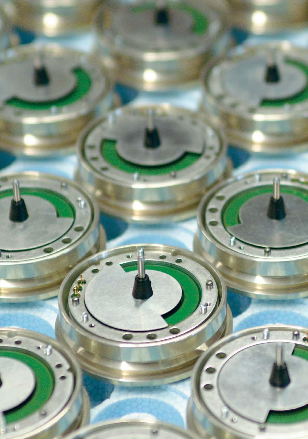
5 Introduction Transmitters for angular position 3 Positioning tasks have to be solved in all areas of machine and plant construction. Safety demands and requirements continually rise, particularly so if failures endanger people and the environment. Angular position, inclination or position transmitters are used for the exact acquisition and monitoring of positions. The ability of allocating an exact and unambiguous position value to a distance or angular position at any time make angular position transmitters one of the most important links between mechanical components and the control system. Angular position transmitters acquire the angular position of a shaft and convert the mechanical movement into a proportionate DC signal. They may be divided into two main categories. Incremental angular position transmitters An incremental encoder measures angles by counting measuring steps or the interpolation of signal periods always starting from an optional point of reference (zero). A pulse is emitted for each position step. This measuring method does not provide an absolute allocation of a position to the signal. This means that every time the control is activated or after an interruption of the supply voltage, a point of reference has to be set. Absolute angular position transmitters Absolute angular position transmitters provide an unambiguously allocated position immediately after activation or an interruption of the supply voltage. Contrary to incremental angular position transmitters, the time-consuming determination of a point of reference is not required. The measuring task of an angular position transmitter may be solved by different measuring principles. Capacitive measuring principle Capacitive measuring principles are among the best non-contact sensor scanning systems for analog and digital output signals. The principle of an ideal plate capacitor. The measured value generator consists of two capacitor plates fixed in a housing and facing each other at a short distance. An electric field is generated between the plates and influenced by a flag which can rotate around a central axis fixed on one axis. A spacer ring is arranged between the emitting and receiving electrode plate and ensures a firm, defined distance of the electrode plates and the flag. The analysis electronics are positioned on the outer side of the capacitor plates where they are supplied with energy via feedthrough filters and read out. Together with the shells of the aluminium housing, these feedthrough filters form an effective protection against external electric fields influencing the angular position transmitter. If the axis is turned in relation to the housing, the capacities of the differential capacitors change in accordance with the angle position of the axis. These changes are acquired by the measuring circuit and correspondingly displayed. The measured value is thus issued as an absolute angle position. Magnetic measuring principle Angular position encoders using a magnetic measuring principle consist of a rotatable shaft with a fixed permanent magnet and a sensor. The magnetic field generated by the permanent magnet is scanned by the sensor and the measured value is allocated to an un ambiguous, absolute angle position. Optical measuring principle Angular position encoders using an optical measuring principle consist of a rotatable shaft with a code disk and an optoelectronic scanning unit composed of an aperture and photoreceivers. Optical information is converted into electrically analysable signals. The system is predominantly limited to visible light, infrared radiation and ultraviolet light. The principle is based on the signal change caused by the quantum mechanical properties of light. This means that infrared light of a source penetrates the code disk and the aperture behind it. In each angle step, a different number of photoreceivers is covered due to the dark fields of the code disk. Single and multiturn angular position encoders Angular position encoders which issue an absolute position by one revolution of the shaft, i.e. 360, are called single turn angular position encoders. The entire measuring range has been covered after one revolution and starts again with its initial value. Many applications, e.g. spindles, engine shafts or cables require the acquisition of several revolutions. Multiturn angular position encoders provide in addition to the angle position of the shaft also information on the number of revolutions. Camille Bauer AG offers a range of sophisticated and high-quality angular position transmitters. For a long time, the company has focussed on the patented capacitive measuring principle. The instruments are characterised by features and advantages which predestine them for heavy-duty operation. The emphasis is always on quality, reliability and robustness. Common applications Wind and solar energy plants Horizontal nacelle alignment to determine the wind direction, monitor the rotor blade position and speed of the rotor Exact alignment of solar panels and parabolic mirrors Guide vanes, throttle valves and slidegates of power plants Exact positioning and monitoring of guide vanes, turbine controls, throttle valves and slidegates Shipping Exact determination of rudder and propeller position Crane vehicles, fork-lift trucks and heavyduty vehicles Exact positioning of crane jibs and the fork of fork-lift trucks Precise position measurement in industrial and dockside cranes as well as swivel measurement in heavy-duty vehicles Dredgers and drilling equipment Measurement of suction arm depths in suction dredgers Acquisition and positioning of dredger arms and depth measurement in rotary drilling equipment
6 Introduction 4 Inclination transmitter The determination of the exact position of an object is important when monitoring moving objects. There is hardly any moving object whose position cannot be monitored by an inclination transmitter. They are the allrounders in instrumentation. Applications cover from the acquisition of the angular position of crane jibs, the lateral inclination of vehicles, the orientation of lifting platforms, of weir traps and similar facilities through to machine monitoring. Inclination transmitters work like a plummet. They measure the deviation from the horizontal or vertical within the reference point provided by the direction of gravity. In relation to angular position transmitters, inclination transmitters feature the advantage of a direct acquisition of inclination values in which they do not require any mechanical interconnection with the actuators. One or two inclination axes are monitored depending on the application purpose of the object. For this reason, inclination transmitters are divided into two types. One-dimensional inclination transmitters As the name indicates, a one-dimensional inclination transmitter can only measure one axis. Two-dimensional inclination transmitters Two axes can be measured simultaneously. A separate measured value is available for both axes. The base plate must be horizontally aligned, i.e. parallel to the horizontal plane. The inclination angle in relation to the surface of the earth can be measured by different methods. Oil-damped pendulum system In this method, a test mass in form of a pendulum surrounded by oil is changed in its position by inclination or gravitational acceleration. The angle is measured by the pendulum swing. oil-damped pendulum system axis X Liquid level analysis In liquid levels, the medium to be measured always aligns itself vertically in relation to gravity. Electrodes are arranged parallel to the tilting axis on the bottom of an electrolyte chamber filled with conductive liquid. If alternating current is applied between the two electrodes, a stray field develops. The stray field is constricted as tilting of the sensor reduces the liquid level. The constant conductibility of the electrolyte causes a resistance change related to the level. If electrodes are arranged in pairs on the right and left half of the bottom of the sensor cell in relation to the tilt axis, the inclination angle can be determined by the differential measurement principle. Thermic method The thermic method uses convection: A gas heated in a measuring cell always rises. Temperature sensors are arranged around the measuring cell which acquire the direction of the generated flow of heat according to a difference method. The inclination angle is determined on basis of the temperature change. Microelectromechanical system (MEMS) Another measuring method concerns the microelectromechanic system (MEMS). The design of the MEMS sensor element is based on a fixed and a movable electrode in form of two engaging comb structures (or interdigital structures). An acceleration in the direction of the measuring axis moves the mass and changes the capacity values between the fixed and the moveable electrodes. This capacity change is processed by the integrated ASIC and converted into an output signal which can easily be acquired for measuring purposes. N S μc The one-dimensional inclination transmitters used by Camille Bauer are based on the magnetic measuring principle with an oildamped pendulum system. The instruments are characterised by numerous special features which predestine them for heavyduty operation. The emphasis is always on quality, reliability and robustness. Common applications Solar energy plants Exact alignment of solar panels and parabolic mirrors Throttle valves and slidegates of power plants Exact acquisition of weir trap positions Shipping and offshore plants Exact acquisition of the lateral inclination of ships and offshore plants Exact acquisition of the position of a lifting platform Crane vehicles, fork-lift trucks and heavy duty vehicles Exact positioning of a crane jib Exact acquisition of the lateral inclination of a vehicle Dredgers and drilling equipment Exact acquisition and positioning of dredger arms Exact acquisition of the lateral inclination of a dredger or drill
7 Transmitters for Angular Position Content Transmitters for Angular Position Programmable shaft transmitter for angular position for heavy duty applications, dia. 58 mm KINAX WT Programmable hollow-shaft transmitter for angular position for heavy duty applications, dia. 78 mm KINAX HW Shaft transmitter for angular position for heavy duty applications, > dia. 100 mm KINAX WT KINAX WT707-SSI Programmable shaft transmitter for angular position for heavy duty applications, > dia. 100 mm KINAX WT KINAX WT707-CANopen Shaft transmitter for angular position to be installed KINAX 3W Programmable shaft transmitter for angular position to be installed KINAX 2W Shaft transmitter for angular position for surface mounting KINAX WT Programmable shaft transmitter for angular position for surface mounting KINAX WT


8 Transmitters for Angular Position Programmable shaft transmitter for angular position for heavy duty applications, dia. 58 mm KINAX WT720 Converts the angular position of a shaft into a load independent direct current signal, proportional to the angular shaft position. The unit is contact free. 6 Main features Robust transmitter for angular position suitable for field applications Highest degree of mechanical and electrical safety Capacitive scanning system provides absolute position immediately after activation Measuring range and sense of rotation can be adjusted by a switch and two push-buttons Zero position and end position are independently adjustable Linear and V characteristic of the output value free programmable No wear, low annual maintenance and mountable anywhere Vibration and shock-resistant Analog output signal 4 20 ma, 2-wire connection Technical data Measuring range: Free programmable between Measuring output: 4 20 ma, 2-wire connection Power supply: V DC (protected against wrong polarity) Output variable I A : Load-independent DC current, proportional to the input angle Max. residual ripple: < 0.3% p.p. Accuracy: Error limit ±0.5% (at reference conditions) Sense of rotation: Adjustable for sense of rotation clockwise or counterclockwise Electrical connection: Spring-type terminal block or plug connector M12, 4 poles Mechanical data Starting torque: < 0.03 Nm Clearance influence: ±0.1% Drive shaft diameter: Admissible static loading of shaft: Mounting position: Material: Connections: Weight: 10 mm 19 mm, with adapter flange NLB1019 Max. 80 N (radial) Max. 40 N (axial) Any Front: aluminium Back: aluminium anodized Shaft: rust-proof, hardened steel Cable gland metal or plug metal (M12 / 4 poles) Approx. 360 g Approx. 900 g, with adapter flange NLB1019 with adapter flange NLB1019 Environmental conditions Temperature range: C C with improved climatic rating) Humidity: Relative humidity max. 90%, non-condensing Relative humidity max. 95%, non-condensing (with improved climatic rating) Housing protection: IP 67 according to EN IP 69k according to EN Vibration: IEC , 100 m/s 2 / Hz Shock: Electromagnetic compatibility: IEC , 500 m/s 2 / 11 ms The standards for noise immunity EN and interference emission EN are observed
 are free adjustable via DIP switch.")
9 Transmitters for Angular Position Programming: The transmitter is programmable via switch and push-button. These will be visible after opening the top cover. Zero and end position can be independently programmed via push-buttons. The direction of rotation and the shape of the output curve (linear or V characteristic) are free adjustable via DIP switch. Connection allocation plug Pin Plug not connected 4 7 Dimensions h M4x6 Ø10 h Dimensions KINAX WT720 M6 Ø62 f8 Ø60 Ø19 f6 Ø ± Dimensions KINAX WT720 with adapter flange NLB1019 Accessories Article No. Description see page Plug connector for M12 sensor plug, 5 poles Mounting angle Mounting plate Kit mounting clamp 39

10 Transmitters for Angular Position Programmable hollow-shaft transmitter for angular position for heavy duty applications, dia. 78 mm KINAX HW730 Converts the angular position of a shaft into a load independent direct current signal, proportional to the angular shaft position. The unit is contact free. 8 Main features Robust transmitter for angular position suitable for field applications Highest degree of mechanical and electrical safety Proven capacitive scanning system No wear, low annual maintenance and mountable anywhere Vibration and shock-resistant Measuring range, sense of rotation, zero position and linear/v characteristic can be adjusted by a switch and two push-buttons Analog output signal 4 20 ma, 2-wire connection Zero position and end position are independently adjustable Capacitive scanning system provides absolute position immediately after activation Technical data Measuring range: Free programmable between Measuring output: 4 20 ma, 2-wire connection Power supply: V DC (protected against wrong polarity) Output variable I A : Load-independent DC current, proportional to the input angle Reproducibility: < 0.1 Accuracy: Error limit ±0.35 (at reference conditions) Sense of rotation: Adjustable for sense of rotation clockwise or counterclockwise Electrical connection: Spring-type terminal block or plug connector M12, 4 poles Mechanical data Starting torque: max 0.7 Nm Clearance influence: ±0.1% Hollow-shaft diameter: 30 mm, by reduction 10, 12, 16 or 20 mm Mounting position: Any Material: Front: aluminium Back: aluminium anodized Shaft: rust-proof, hardened steel Connections: Cable gland metal or plug metal (M12 / 4 poles) Weight: Approx. 820 g Environmental conditions Temperature range: C Humidity: Relative humidity max. 95%, non-condensing Housing protection: IP 67 according to EN IP 69k according to EN Vibration: IEC , 100 m/s 2 / Hz Shock: IEC , 1000 m/s 2 / 11 ms Electromagnetic compatibility: The standards for noise immunity EN and interference emission EN are observed
 are free adjustable via DIP switch.")
11 Transmitters for Angular Position Programming: The transmitter is programmable via switch and push-button. These will be visible after opening the top cover. Zero and end position can be independently programmed via push-buttons. The direction of rotation and the shape of the output curve (linear or V characteristic) are free adjustable via DIP switch. Connection allocation plug Pin Plug not connected 4 9 Dimensions 55,7 55,7 M4 Ø50 65,5 28 H , , max. 77 Accessories Article No. Description see page Plug connector for M12 sensor plug, 5 poles Adapter sleeve ø10mm Adapter sleeve ø12mm Adapter sleeve ø16mm Adapter sleeve ø20mm Kit of torque support HW730 39


 0... 10, 0... 30, 0... 60, 0... 90, 0... 180, 0... 270 up to max. 1600 turns (with additional gear) Measuring output: 0 1 ma, 0... 5 ma, 0.")
12 Transmitters for Angular Position 10 Shaft transmitter for angular position for heavy duty applications, > dia. 100 mm Converts the angular position of a shaft into a load independent direct current signal, proportional to the angular shaft position. The unit is contact free and has minimal mechanical abrasion. Main features Robust transmitter for angular position in singleturn und multiturn suitable for field applications Highest degree of mechanical and electrical safety Capacitive scanning system provides absolute position immediately after activation No wear, low annual maintenance and mountable anywhere Zero position and end position are adjustable Small bearing play influence < 0.1% Available with explosion protection Intrinsic safety Ex ia IIC T6 Can be mounted in hazardous area Also available as sea-water resistant version Technical data Measuring range: , , , , , , (without gear) , , , , , up to max turns (with additional gear) Measuring output: 0 1 ma, ma, ma, ma, 4 20 ma with 3 or 4-wire connection ma with 2-wire connection Output variable I A : Load-independent DC current, proportional to the input angle Current limitation: I A max. 40 ma Residual ripple in output current: <0.3% p.p. Power supply: DC and AC voltage (DC/AC power pack) Nominal voltage UN Tolerance V DC / AC DC % V DC / AC AC ±15% DC voltage only V DC (version non-intrinsically safe, without electric isolation) V DC (version intrinsically safe, without electric isolation) Max. current consumption approx. 5 ma + I A Max. residual ripple 10% p.p. (must not fall below 12 V) Accuracy: Error limit 0.5% for ranges Error limit 1.5% for ranges of up 0... >150 to Reproducibility: <0.2% Response time: Electrical connection: <5 ms Plug connector or cable glands, connection print with screw terminals Mechanical data Starting torque: Approx. 25 Ncm Clearance influence: ±0.1% Drive shaft diameter: 19 mm or 12 mm Admissible static loading of shaft: Max N (radial) Max. 500 N (axial) Mounting position: Any Material: Housing flange standard: steel Housing flange sea-water: high-grade steel Housing cover with plug connector: plastic Housing cover with cable glands: aluminium Shaft: rust-proof hardened steel Weight: Approx. 2.9 kg (without additional gear) Approx. 3.9 kg (with additional gear) KINAX WT707 Version with plug connector Sea-water resistant version
 40... +75 C at T5 (version intrinsically safe) Humidity: Relative humidity max. 90%, non-condensing Relative humidity max.")
13 Transmitters for Angular Position Version with additional gear Environmental conditions Temperature range: C C (with improved climatic rating) C at T6 (version intrinsically safe) C at T5 (version intrinsically safe) Humidity: Relative humidity max. 90%, non-condensing Relative humidity max. 95%, non-condensing (with improved climatic rating) Housing protection: IP 66 acc. to EN Vibration: IEC , 10g continuously, 15g (every 2 h in 3 directions) / Hz 5g continuously, 10g (every 2 h in 3 directions) / Hz Shock: Electromagnetic compatibility: Explosion protection: Dimensions IEC , 3 x 50g (10 pulses per axis and direction) The standards for noise immunity EN and interference emission EN are observed Intrinsically safe Ex II 2 G / Ex ia IIC T6 acc. to EN : 2006 and EN : Ø 62 f8 Ø 60 Ø 19 f6 approx approx M6 15 Ø 62 f8 Ø 60 Ø 19 f6 approx approx M6 15 Sea-water resistant version with additional gear approx. 25 approx M ± approx. 25 approx M ± Ø 62 f8 Ø 60 Ø 19 f PG 11 approx ± Ø 62 f8 Ø 60 Ø 19 f approx. 71 PG ± Auxiliary transmission Using an optimum auxiliary transmission KINAX WT707 can also be employed for multiturn applications. The selection of the correct gear ratio results in up to 1600 revolutions. You may choose auxiliary transmissions with a gear ratio from 2:1 up to 1600:1. Special sea water design Using the special sea water design, KINAX WT707 can be employed under extreme environmental conditions. The special steel housing makes it particularly suited to applications in aggressive media like sea water, lyes, acids and cleaning agents. Data on explosion protection (type of protection Intrinsic safety ) Marking Mounting location of Order Code Certificates Instrument Meas. output the instrument Ex ia IIC T6 U i = 30 V I i = 160 ma P i = 1 W C i 10 nf L i = 0 ZELM 10 ATEX 0427X Within the hazardous area, zone 1 Accessories Article No. Description see page Mounting foot Mounting flange 41

14 Transmitters for Angular Position Shaft transmitter for angular position for heavy duty applications, > dia. 100 mm KINAX WT707-SSI The KINAX WT707-SSI transmitter is a precision instrument. It serves the acquisition of angular position and rotation, processing and the provision of measured values as electric output signals for the downstream device. 12 Main features Robust SSI-transmitter for angular position in singleturn and multiturn suitable for field applications Highest degree of mechanical and electrical safety Absolute position immediately after activation No wear, low annual maintenance and mountable anywhere Zero setting input Also available as sea-water resistant version Technical data Measuring range: Power supply: V DC Power consumption: Typ. 50 ma (at 24 V DC) Measuring output: SSI, antivalent RS422 Signal coding: Binary or gray-code Max resolution: Singleturn 12 bit (1 measuring step = 5 16 ) Multiturn 13 bit (8192 turns) Accuracy: Error limit ±1 Repeatability: 0.3 Max. clock rate: 1 MHz Zero setting signal: Zero setting: < 0.4 V, min. 2 ms Idle position: 3.3 V or open Direction of rotation: Looking at the flange in clockwise rotation increasing position values result Electrical connection: Plug connector M12, 8 poles Sea-water resistant version Mechanical data Starting torque: Approx. 25 Ncm Clearance influence: ±0.1% Drive shaft diameter: 19 mm or 12 mm Admissible static loading of shaft: Max N (radial) Max. 500 N (axial) Mounting position: Any Material: Housing flange standard: steel Housing flange sea-water: high-grade steel Housing cover with plug connector: aluminium Shaft: rust-proof hardened steel Weight: Approx. 2.9 kg Environmental conditions Temperature range: C Humidity: Relative humidity max. 95%, non-condensing Housing protection: IP 66 according to EN Vibration: IEC , 300 m/s 2 / Hz Shock: IEC , 1000 m/s 2 / 6 ms Electromagnetic compatibility: The standards for noise immunity EN and interference emission EN are observed
15 Transmitters for Angular Position Dimensions (without connector) M6 15 Ø 62 f8 Ø 60 Ø 19 f ± Readout of positional values t1 T n clock t3 clock data t2 Bit n Bit n-1 Bit 3 Bit 2 Bit 1 Output circuits encoder circuit schematic typical user interface encoder circuit schematic typical user interface +Vs +Vs +Vs +Vs e.g. MAX 490 Data 100 Ω 0 V 0 V e.g.mc 3489 SN AM 26 LS 32A 100 Ω Clock 0 V 0 V Pin configuration of connector Pin Cable colour Signals Description 1 White 0 V Power supply 2 Brown +Vs Power supply 3 Green Clock + Clocking lead Yellow Clock Clocking lead Grey Data + Data line 6 Pink Data Data line 7 Blue Zero Zero setting input 8 Red open Not connected Shield Housing Special sea water design Using the special sea water design, KINAX WT707-SSI can be employed under extreme environmental conditions. The special steel housing makes it particularly suited to applications in aggressive media like sea water, lyes, acids and cleaning agents. Accessories Article No. Description see page Plug connector for M12 sensor plug, 8 poles Mounting foot Mounting flange 41
16 Transmitters for Angular Position Programmable shaft transmitter for angular position for heavy duty applications, > dia. 100 mm KINAX WT717 Converts the angular position of a shaft into a load independent direct current signal, proportional to the angular shaft position. The unit is contact free and has minimal mechanical abrasion. 14 Main features Robust transmitter for angular position in singleturn and multiturn suitable for field applications Highest degree of mechanical and electrical safety Capacitive scanning system provides absolute position immediately after activation No wear, low annual maintenance and mountable anywhere Measuring range, sense of rotation, characteristic, switching point programmed using PC Adjustement / Independent fine adjustment of the analog output, zero position and measuring range Simulation of measured values / The testing of the subsequent device chain is already possible during the installation phase Measured value acquisition / Display of the instantaneous value and a trend graph of the measured value on the screen Characteristic of the output value / Programmable as a linear, V-characteristic, or any characteristic curve Small bearing play influence < 0.1% Available with explosion protection Intrinsic safety Ex ia IIC T6 Can be mounted within the hazardous area Also available as sea-water resistant version Technical data Measuring range: Measuring output: Output variable I A : Current limitation: Power supply: Programmable between , , (without gear) Programmable between , , up to max turn (with gear) ma with 2-wire connection Load-independent DC current, proportional to the input angle I A max. 40 ma V DC (version non-intrinsically safe, without electric isolation) V DC (version intrinsically safe, without electric isolation) Power consumption max.: Approx. 5 ma + I A Residual ripple in output current: < 0.3% p.p. Accuracy: Error limit ±0.5% Reproducibility: < 0.2% Response time: < 5 ms Electrical connection: Cable glands, connection print with screw terminal Sea-water resistant version Mechanical data Starting torque: Approx. 25 Ncm Clearance influence: ±0.1% Drive shaft diameter: 19 mm or 12 mm Admissible static loading of shaft: Max N (radial) Max. 500 N (axial) Mounting position: Any Material: Housing flange standard: steel Housing flange sea-water: high-grade steel Housing cover with cable glands: aluminium Shaft: rust-proof hardened steel Weight: Approx. 2.9 kg (without additional gear) Approx. 3.9 kg (with additional gear)
 40... +71 C at T5 (intrinsically safe version) Humidity: Relative humidity max. 90%, non-condensing Relative humidity max.")
 Shock: IEC 60 068-2-27, 500 m/s 2 (10 pulses per axis and direction) Electromagnetic compatibility: The standards for noise immunity EN 61 000-6-2 and")
17 Transmitters for Angular Position Version with additional gear Environmental conditions Temperature range: C C (with improved climatic rating) C at T6 (intrinsically safe version) C at T5 (intrinsically safe version) Humidity: Relative humidity max. 90%, non-condensing Relative humidity max. 95%, non-condensign (with improved climatic rating) Housing protection: IP 66 according to EN Vibration: IEC , 50 m/s 2 / Hz (every 2 h in 3 directions) Shock: IEC , 500 m/s 2 (10 pulses per axis and direction) Electromagnetic compatibility: The standards for noise immunity EN and interference emission EN are observed Explosion protection: Intrinsically safe Ex II 2 G / Ex ia IIC T6 acc. to EN : 2006 and EN : Programming: Interface: Serial interface A PC, the programming cable PK 610 plus ancillary cable and the configuration software 2W2 (see section Software and accessories ) are required to program the KINAX W717. Dimensions See-water resistant version with additional gear ± ± Auxiliary transmission Using an optimum auxiliary transmission KINAX WT717 can also be employed for multiturn applications. The selection of the correct gear ratio results in up to 1600 revolutions. You may choose auxiliary transmissions with a gear ratio from 2:1 up to 1600:1. Special sea water design Using the special sea water design, KINAX WT717 can be employed under extreme environmental conditions. The special steel housing makes it particularly suited to applications in aggressive media like sea water, lyes, acids and cleaning agents. Data on explosion protection (Type of protection Intrinsic safety ) Order Code Marking Instrument Meas. output Certificates U i = 30 V I i = 160 ma Ex ia IIC T6 P i = max. 1 W ZELM 03 ATEX 0123 C i 6.6 nf L i = 0 Mounting location of the instrument Within the hazardous area, zone 1 Accessories Article No. Description see page Mounting foot Mounting flange 41
18 Transmitters for Angular Position Programmable shaft transmitter for angular position for heavy duty applications, > dia. 100 mm KINAX WT707-CANopen 16 Converts the angular position of a shaft into a load independent direct current signal, proportional to the angular shaft position. The unit is contact free and has minimal mechanical abrasion. Main features Robust CANopen-transmitter for angular position in singleturn and multiturn suitable for field applications Highest degree of mechanical and electrical safety Absolute position immediately after activation No wear, low annual maintenance and mountable anywhere Resolution and zero point may be programmable Also available as sea-water resistant version Magnetic measuring principle Technical data Measuring range: Power supply: V DC Max. power consumption: Typ. 100 ma (at 24 V DC) Measuring output: CAN-Bus standard ISO/DIS Protocole: CANopen Profil: CANopen CIA, DS-301 V4.01 DSP-305 V1.0, DS-406 V3.0 CAN-specification: CAN 2.0B Operating mode: Event-triggered / Time-triggered Remotely-requested Sync (cyclic) / Sync-Code Signal coding: Natural binary code Max. resolution: Singleturn 12 bit (1 measuring step = 5 16 ) Multiturn 13 bit (8192 turns) Accuracy: Error limit ± 1 Repeatability: 0.3 Max. Baudrate: Direction of rotation: 1 MBit/s Parameterisable, rising position values as a standard when viewing the flange side and clockwise rotation of the shaft Electrical connections: Plug connector M12, 8 poles Mechanical data Starting torque: Approx. 25 Ncm Clearance influence: ±0.1% Drive shaft diameter: 19 mm or 12 mm Admissible static loading of shaft: Max N (radial) Mounting position: Material: Max. 500 N (axial) Any Housing flange standard: steel Housing flange sea-water: high-grade steel Housing cover with cable glands: aluminium Shaft: rust-proof hardened steel Weight: Approx. 2,9 kg Environmental conditions Temperature range: C Humidity: Relative humidity max. 95%, non-condensing Housing protection: IP 66 according to EN Vibration: IEC , 300 m/s 2 / Hz Shock: IEC , 1000 m/s 2 / 6 ms Electromagnetic compatibility: The standards for noise immunity EN and interference emission EN are observed Sea-water resistant version
19 Transmitters for Angular Position Dimensions (without connector) M6 15 Ø 62 f8 Ø 60 Ø 19 f ± Pin configuration of connector Pin Signals 1 CAN Shld V DC 3 GNC 4 CAN High 5 CAN Low Special sea water design Using the special sea water design, KINAX WT707-CANopen can be employed under extreme environmental conditions. The special steel housing makes it particularly suited to applications in aggressive media like sea water, lyes, acids and cleaning agents. Accessories Article No. Description see page Plug connector for M12 sensor plug, 5 poles Mounting foot Mounting flange 41


20 Transmitters for Angular Position Shaft transmitter for angular position to be installed KINAX 3W2 Converts the angular position of a shaft into a load independent direct current signal, proportional to the angular shaft position. The unit is contact free and has minimal mechanical abrasion. 18 Main features Compact transmitter for angular position to be installed into other equipments Capacitive scanning system provides absolute position immediately after activation No wear, low annual maintenance and mountable anywhere Adjustable zero point and measuring span Small bearing play influence < 0.1% Small starting torque < Ncm Available with explosion protection Intrinsic safety Ex ia IIC T6 Can be mounted within the hazardous area Technical data Measuring range: , , , , , Measuring output: 0 1 ma, ma, ma, ma, ma Each with 3 or 4-wire connection ma with 2-wire connection Power supply: V DC (version non-intrinsically safe) V DC (version intrinsically safe) Residual ripple in output current: < 0.3% p.p. Residual ripple max.: 10% p.p. (must not fall below 12 V) Accuracy: Error limit ±0.5% for ranges Error limit 1.5% for ranges of 0... > 150 to Reproducibility: < 0.2% Response time: < 5 ms Electrical connection: Soldering terminals (protection class IP 00 acc. to EN ) or wiring print with screw terminals or wiring print with AMP connections or wiring print with pads or wiring print with trans-zorb-diode Mechanical data Starting torque: < Ncm with shaft 2 mm < 0.03 Ncm with shaft 6 mm resp. 1/4 Clearance influence: ±0.1% Drive shaft diameter: 2 mm, 6 mm or 1/4 Admissible static loading of shaft : Sense Drive shaft diameter 2 mm 6 mm resp. 1/4 radial max 16 N 83 N axial max 25 N 130 N Wiring print with screw terminals Wiring print with AMP connections Wiring print with pads Mounting position: Material: Weight: Any Chromated aluminium Shaft: rust-proof hardened steel Approx. 100 g Wiring print with trans-zorb-diode
21 Transmitters for Angular Position Environmental conditions Temperature range: C C (with improved climatic rating) C at T6 (intrinsically safe version) C at T5 (intrinsically safe version) Humidity: Relative humidity max. 90%, non-condensing Relative humidity max. 95%, non-condensing (with improved climatic rating) Housing protection: IP 50 according to EN Vibration: IEC , 50 m/s 2 / Hz (every 2 h in 3 directions) Shock: IEC , 500 m/s 2 (10 pulses per axis and direction) Electromagnetic compatibility: The standards for noise immunity EN and interference emission EN are observed Explosion protection: Intrinsically safe Ex II 2 G / Ex ia IIC T6 acc. to EN : 2006 and EN : Dimensions 48 M3 4.5 low ±0.1 Ø 20 f7 Ø 40 f7 Ø 20 f7 Ø 40 f Ø Ø6 g Data on explosion protection (Type of protection Intrinsic safety ) Order Code Marking Instrument Meas. output U i = 30 V I i = 160 ma Ex ia IIC T6 P i = 1 W C i 10 nf L i = 0 Certificate ZELM 10 ATEX 0427X Mounting location of the device Within the hazardous area


22 Transmitters for Angular Position Programmable shaft transmitter for angular position to be installed KINAX 2W2 Converts the angular position of a shaft into a load independent direct current signal, proportional to the angular shaft position. The unit is contact free and has minimal mechanical abrasion. 20 Main features Compact transmitter for angular position to be installed into other equipments Capacitive scanning system provides absolute position immediately after activation No wear, low annual maintenance and mountable anywhere Measuring range, sense of rotation, characteristic, switching point programmed using PC Adjustement / Independent fine adjustment of the analog output, zero position and measuring range Simulation of measured values / The testing of the subsequent device chain is already possible during the installation phase Measured value acquisition / Display of the instantaneous value and a trend graph of the measured value on the screen Characteristic of the output value / Programmable as a linear, V-characteristic, or any characteristic curve Small bearing play influence < 0.1% Small starting torque < Ncm Available with explosion protection Intrinsic safety Ex ia IIC T6 Can be mounted within the hazardous area Technical data Measuring range: Programmable between , , Measuring output: ma with 2-wire connection Power supply: V DC (non intrinsically safe version) V DC (intrinsically safe version) Residual ripple in output current: < 0,3% p.p. Accuracy: Error limit ±0.5% Reproducibility: < 0,2% Response time: < 5 ms Electrical connections: Soldering terminals (protection class IP 00 acc. to EN ) or wiring print with screw terminals Wiring print with screw terminals Mechanical data Starting torque: < Ncm with shaft 2 mm < 0.03 Ncm with shaft 6 mm resp. 1/4 Clearance influence: ±0.1% Drive shaft diameter: 2 mm, 6 mm or 1/4 Admissible static loading of shaft: Sense Drive shaft diameter 2 mm 6 mm resp. 1/4 radial max 16 N 83 N axial max 25 N 130 N Mounting position: Material: Weight: Any Chromated aluminium Shaft: rust-proof hardened steel Approx. 100 g
23 Transmitters for Angular Position Environmental conditions Temperature range: C C (with improved climatic rating) C at T6 (intrinsically safe version) C at T4 (intrinsically safe version) Humidity: Relative humidity max. 90%, non-condensing Relative humidity max. 95%, non-condensing (with improved climatic rating) Housing protection: IP 50 according to EN Vibration: IEC , 50 m/s 2 / Hz (every 2 h in 3 directions) Shock: IEC , 500 m/s 2 (10 pulses per axis and direction) Electromagnetic compatibility: The standards for noise immunity EN and interference emission EN are observed Explosion protection: Intrinsically safe Ex II 2 G / Ex ia IIC T6 acc. to EN : 2006 and EN : Programming: Interface: Serial interface A PC, the programming cable PK610 plus ancillary cable and the configuration software 2W2 (see section Software and accessories ) are required to program the KINAX 2W2. Dimensions 48 M3 4.5 low ±0.1 Ø 20 f7 Ø 40 f7 Ø 20 f7 Ø 40 f Ø Ø6 g Basic configuration Order Code Mechanical angle range Measuring range Switching point Sense of rotation Characteristic of output variable Clockwise linear Clockwise linear Data on explosion protection (Type of protection Intrinsic safety ) Order Code Marking Instrument Meas. output Certificate U i = 30 V I i = 160 ma Ex ia IIC T6 P i = 1 W ZELM 03 ATEX 0123 C i = 6.6 nf L i = 0 Mounting location of the instrument Within the hazardous area, zone 1
24 Transmitters for Angular Position Shaft transmitter for angular position for surface mounting KINAX WT710 Converts the angular position of a shaft into a load independent direct current signal, proportional to the angular shaft position. The unit is contact free and has minimal mechanical abrasion. 22 Main features Transmitter for angular position for surface mounting for building onto other equipments in singleturn and multiturn Capacitive scanning system provides absolute position immediately after activation No wear, low annual maintenance and mountable anywhere Adjustement of the zero position and measuring range Small bearing play influence < 0.1% Small starting torque < Ncm Available with explosion protection Intrinsic safety Ex ia IIC T6 Can be mounted within the hazardous area Technical data Measuring range: , , , , , , (without gear) , , , , , up to max. 48 turns (with additional gear) Measuring output: 0 1 ma, ma, ma, ma, ma each with 3 or 4-wire connection ma with 2-wire connection Nominal voltage: Nominal voltage U N Tolerance V DC / AC DC % V DC / AC AC ±15% Power supply: V DC (non intrinsically safe version) V DC (intrinsically safe version) Residual ripple in output current: < 0.3% p.p. Max. residual ripple: 10% p.p. (must not fall below 12 V) Accuracy: Error limit ±0.5% for ranges Error limit 1.5% for ranges of 0... > 150 to Reproducibility: < 0.2% Response time: < 5 ms Electrical connections: Screw type terminals and cable glands Mechanical data Starting torque: Clearance influence: ±0.1% Drive shaft diameter: 2 mm, 6 mm or 1/4 Admissible static loading of shaft: Sense Mounting position: < Ncm with shaft 2 mm (without additional gear) < 0.03 Ncm with shaft 6 mm resp. 1/4 Welle (without additional gear) Ncm depending on transmission ratio (with additional gear) Drive shaft diameter 2 mm 6 mm resp. 1/4 radial max 16 N 83 N axial max 25 N 130 N Any
25 Transmitters for Angular Position Material: Weight: Housing: aluminium. corrosion resistant finish Plastic protection cap Shaft: rust-proof hardened steel Approx. 550 g (without additional gear) Approx. 900 g (with additional gear) Environmental conditions Temperature range: C C (with improved climatic rating) C at T6 (intrinsically safe version) C at T5 (intrinsically safe version) Humidity: Relative humidity max. 90%, non-condensing Relative humidity max. 95%, non-condensing (with improved climatic rating) Housing protection: IP 43 according to EN (without additional gear) IP 64 according to EN (with additional gear) Vibration: IEC , 50 m/s 2 / Hz (every 2 h in 3 directions) Shock: IEC , 500 m/s 2 (10 pulses per axis and direction) Electromagnetic compatibility: The standards for noise immunity EN and interference emission EN are observed Explosion protection: Intrinsically safe Ex II 2 G / Ex ia IIC T6 acc. to EN : 2006 and EN : Dimensions Ø75-f8 Ø Ø75-f8 Ø6-g Basic version Basic version with additional gear Additional gear for multiturn Order Code Transmission Shaft G 1 : 4 H 4 : 1 J 32 : 1 Shaft dia. 6 mm, length 15 mm K 64 : 1 N 1 : 1 Data on explosion protection (Type of protection Intrinsic safety ) Order Code Marking Instrument Meas. output Certificate U i = 30 V I i = 160 ma Ex ia IIC T6 P i = 1 W ZELM 99 ATEX 0006 C i 10 nf L i = 0 Mounting location of the instrument Within the hazardous area, zone 1

26 Transmitters for Angular Position Programmable shaft transmitter for angular position for surface mounting KINAX WT711 Converts the angular position of a shaft into a load independent direct current signal, proportional to the angular shaft position. The unit is contact free and has minimal mechanical abrasion. 24 Main features Transmitter for angular position for surface mounting for building onto other equipments in singleturn and multiturn Capacitive scanning system provides absolute position immediately after activation No wear, low annual maintenance and mountable anywhere Measuring range, sense of rotation, characteristic, switching point programmed using PC Adjustement / Independent fine adjustment of the analog output, zero position and measuring range Simulation of measured values / The testing of the subsequent device chain is already possible during the installation phase Measured value acquisition / Display of the instantaneous value and a trend graph of the measured value on the screen Characteristic of the output value / Programmable as a linear, V-characteristic, or any characteristic curve Small bearing play influence < 0.1% Small starting torque < Ncm Available with explosion protection Intrinsic safety Ex ia IIC T6 Can be mounted within the hazardous area Technical data Measuring range: Programmable between , , Measuring output: ma with 2-wire connection Power supply: V DC (non intrinsically safe version) V DC (intrinsically safe version) Residual ripple in output current: < 0.3% p.p. Accuracy: Error limit ±0.5% Reproducibility: < 0,2% Response time: < 5 ms Electrical connections: Screw type terminals and cable glands Mechanical data Starting torque: Clearance influence: ±0.1% Drive shaft diameter: 2 mm, 6 mm or 1/4 Admissible static loading of shaft: Sense < Ncm with shaft dia. 2 mm (without additional gear) < 0.03 Ncm with shaft dia. 6 mm resp. 1/4 (without additional gear) Ncm depending on transmission (with additional gear) Drive shaft diameter 2 mm 6 mm resp. 1/4 radial max 16 N 83 N axial max 25 N 130 N Mounting position: Material: Weight: Any Housing: aluminium, corrosion resistant finish Plastic protection cap Shaft: rust-proof hardened steel Approx. 550 g (without additional gear) Approx. 900 g (without additional gear)
27 Transmitters for Angular Position Environmental conditions Temperature range: C C (with improved climatic rating) C at T6 (intrinsically safe version) C at T5 (intrinsically safe version) Humidity: Relative humidity max. 90%, non-condensing Relative humidity max. 95%, non-condensing (with improved climatic rating) Housing protection: IP 43 according to EN (without additional gear) IP 64 according to EN (with additional gear) Vibration: IEC , 50 m/s 2 / Hz (every 2 h in 3 directions) Shock: IEC , 500 m/s 2 (10 pulses per axis and directions) Electromagnetic compatibility: The standards for noise immunity EN and interference emission EN are observed Explosion protection: Intrinsically safe Ex II 2 G / EEx ia IIC T6 acc. to EN : 2006 and EN : 2007 Programming: Interface: Dimensions 6 Serial interface A PC, the programming cable PK610 plus ancillary cable and the configuration software 2W2 (see section Software and accessories ) are required to program the KINAX WT Ø75-f8 Ø Ø75-f8 Ø6-g Basic instrument Additional gear for multiturn Order Code Transmission Shaft G 1 : 4 H 4 : 1 Shaft dia. 6 mm, J 32 : 1 Length 15 mm K 64 : 1 N 1 : 1 Basic configuration Order Code Mechanical angle range 25 Measuring range Basic instrument with additional gear Switching point Sense of rotation 25 Characteristic of output variable Clockwise linear Clockwise linear Data on explosion protection (Type of protection Intrinsic safety ) Order Code Marking Instrument Meas. output Certificate U i = 30 V I i = 160 ma EEx ia IIC T6 P i = 1 W ZELM 99 ATEX 0006 C i 10 nf L i = 0 Mounting location of the instrument Within the hazardous area, zone 1

28 26
29 Position Feedback Transmitters Content Position feedback transmitters Transmitter for position feedback KINAX SR Programmable transmitter for position feedback KINAX SR
30 Position Feedback Transmitters Transmitter for position feedback KINAX SR709 The transmitter is used for to measure and transmit linear displacement (stroke) on various types of control valves and other control devices. The output is a load independent DC signal. Main features Robust transmitter for position feedback Capacitive scanning system provides absolute position immediately after activation No wear, low annual maintenance and mountable anywhere Setting of the measuring range is achieved via adjusting the lever system pivot point Available in type of protection Intrinsic safety Ex ia IIC T6 Can be mounted within the hazardous area 28 Technical data Measuring range: Measuring output: Nominal voltage: mm, mm 0 1 ma, ma, ma, ma, ma each with 3 or 4-wire connection ma with 2-wire connection Nominal voltage U N Tolerance V DC / AC DC % V DC / AC AC ±15% Output variable I A : Current limitation: Power supply: Load-independent DC current, proportional to the input angle I A max. 40 ma V DC (non intrinsically safe version) V DC (intrinsically safe version) Max. current consumption: Approx. 5 ma + I A Residual ripple in output current: < 0.3% p.p. Max. residual ripple: 10% p.p. Accuracy: Linearity error 0.5% Electrical connections: Screw type terminals or cable glands Mechanical data Mounting position: Operating angle: Any Operating lever set for minimum operating angle Operating lever set for maximum operating angle
31 Position Feedback Transmitters Material: Weight: Housing: aluminium Approx g Environmental conditions Temperature range: C C (with improved climatic rating) C at T6 (intrinsically safe version) C at T5 (intrinsically safe version) Humidity: Relative humidity max. 90%, non-condensing Relative humidity max. 95%, non-condensing (with improved climatic rating) Housing protection: IP 54 according to EN Vibration: IEC , 10g continuously, 15g (each 2h in 3 directions) / Hz IEC , 5g continuously, 10g (each 2 h in 3 directions) / Hz Shock: Electromagnetic compatibility: Explosion protection: IEC , 3 x 50g (10 pulses per axis and direction) The standards for noise immunity EN and interference emission EN are observed Intrinsically safe Ex II 2 G / Ex ia IIC T6 acc. to EN : 2006 and EN : Dimensions M PG Data on explosion protection (Type of protection intrinsic safety ) Order Code Marking Instrument Meas. output Certificate U i = 30 V I i = 160 ma Ex ia IIC T6 P i = 1 W ZELM 10 ATEX 0427X C i 10 nf L i = 0 Mounting location of the instrument Within the hazardous area Accessories Article No. Description NAMUR mounting part

32 Position Feedback Transmitters Programmable transmitter for position feedback KINAX SR719 The transmitter is used for to measure and transmit linear displacement (stroke) on various types of control valves and other control devices. The output is a load independent DC signal. Main features Robust transmitter for position feedback Capacitive scanning system provides absolute position immediately after activation No wear, low annual maintenance and mountable anywhere Setting of the measuring range is achieved via adjusting the lever system pivot point Adjustement / Independent fine adjustment of the analog output, zero position and measuring range Simulation of measured values / The testing of the subsequent device chain is already possible during the installation phase Measured value acquisition / Display of the instantaneous value and a trend graph of the measured value on the screen Characteristic of the output value / Programmable as a linear, V-characteristic, or any characteristic curve 30 Technical data Measuring range: mm, mm Measuring output: ma with 2-wire connection Output variable I A : Load-independent DC current, proportional to the input angle Current limitation: I A max. 40 ma Power supply: V DC (non intrinsically safe version) Max. current consumption: Approx. 5 ma + I A Residual ripple in output current: < 0.3% p.p. Accuracy: Linearity error 0.5% Electrical connections: Screw type terminals or cable glands Mechanical data Mounting position: Operating angle: Any Operating lever set for minimum operating range Operating lever set for maximum operating angle Material: Weight: Housing: aluminium Approx g
33 Position Feedback Transmitters Environmental conditions Temperature range: C C (with improved climatic rating) C at T6 (intrinsically safe version) C at T5 (intrinsically safe version) Humidity: Relative humidity max. 90%, non-condensing Relative humidity max. 95%, non-condensing (with improved climatic rating) Housing protection: IP 54 according to EN Vibration: IEC , 10g continuous, 15g (each 2 h in 3 directions) / Hz IEC , 5g continuous, 10g (each 2 h in 3 directions) / Hz Shock: Electromagnetic compatibility: IEC , 3 x 50g (10 pulses per axis and direction) The standards for noise immunity EN and interference emission EN are observed Programming: Interface: Serial interface A PC, the programming cable PK610 plus ancillary cable and the configuration software 2W2 (see section Software and accessories ) are required to program the KINAX SR Dimensions M PG Accessories Article No. Description NAMUR mounting part

34 32
35 Inclination Transmitters Content Inclination transmitters Inclination transmitter unidimensional KINAX N KINAX N702-CANopen KINAX N702-SSI
36 Inclination Transmitters Inclination transmitter unidimensional KINAX N702 The transmitter converts the tilt angle into a direct current signal, proportional to the angle. Tilt angle values of a platform stand for important measuring data as a part of the safety and control system of that type of machinery. Main features Robust magnetoresistive angular position transmitter, conctact free, freely rotatable without stops With oil-damped pendulum system The sensor is contact free and has minimal abrasion on the pendulum Measuring range, sense of rotation and zero position programmed directly at the transmitter Technical data Measuring princip: Magnetoresistive angular position transmitter, contact free, freely rotatable Measuring range: , freely programmable Measuring output: ma with 3-wire connection Power supply: V DC No protection against wrong polarity Current consumption: < 80 ma Load resistant: Max. 600 Ω Accuracy: ±0.2 Resolution: 14 Bit Transient response: By 25 tilts < 1 sec. Electrical connection: Connector M12 x 1, 5 poles 34 Mechanical data Pendulum damping: Mounting position: Material: Weight: With silicon oil Any Housing: coated aluminium Approx. 300 g Environmental conditions Temperature range: C Humidity: Relative humidity max. 90%, non-condensing Housing protection: IP 66 according to EN Vibration: IEC , 40 m/s 2 / Hz Pin configuration of connector M12 Pin assignments = 0 V 2 = +24 V 4 = +20 ma or +10 V Dimensions Ø50 f7 Ø58 Ø Ø6.4 Ø11

37 Inclination Transmitters KINAX N702-CANopen Inclination transmitter unidimensional The transmitter converts the tilt angle into a direct current signal, proportional to the angle. Tilt angle values of a platform stand for important measuring data as a part of the safety and control system of that type of machinery. Main features Robust magnetoresistive CANopen angular position transmitter, conctact free, freely rotatable without stops With oil-damped pendulum system The sensor is contact free and has minimal abrasion on the pendulum Pendulum shaft has no mechanical stops and can be 360 infinitely rotated Reduced wiring expenditure Autoconfiguration of the network Comportable access of all instrument parameters Instrument synchronisation, simultaneous data read-in and read-out Technical data Measuring principle: Magnetoresistive angular position transmitter, contact free, freely rotatable Measuring range: Tilt angle: Measuring output: CAN-Bus interface Protocole: CANopen Power supply: V DC, no protection against wrong polarity Power consumption: < 80 ma Baudrate: 1 MBit/s Accuracy: ±0,2 Resolution: 14 Bit Transient response: By 25 tilts < 1 sec. Electrical connection: Connector M12 x 1, 5 poles Mechanical data Pendulum damping: With silicon oil Mounting position: Any Material: Housing: coated aluminium Weight: Approx. 300 g Environmental conditions Temperature range: C Humidity: Relative humidity max. 90%, non-condensing Housing protection: IP 66 according to EN Vibration: IEC , 40 m/s 2 / Hz 35 Pin configuration of connector M Pin assignments 1 = CAN Shld 2 = +24 V DC 3 = GND 4 = CAN High 5 = CAN Low Dimensions Ø Ø50 f7 Ø58 Ø Ø6.4 Ø11

38 Inclination Transmitters Inclination transmitter unidimensional KINAX N702-SSI The transmitter converts the tilt angle into a direct current signal, proportional to the angle. Tilt angle values of a platform stand for important measuring data as a part of the safety and control system of that type of machinery. 36 Mains feature Robust magnetoresistive angular position transmitter with interface SSI, contact free, freely rotatable without stops With oil-damped pendulum system The sensor is contact free and has minimal abrasion on the pendulum Measuring range, sense of rotation, zero position and measuring span programmed directly at the transmitter Technical data Measuring principe: Magnetoresistive angular position transmitter, contact free, freely rotatable Measuring range: , freely programmable Measuring output: SSI binary code Power supply: V DC, no protection against wrong polarity Power consumption: < 100 ma Accuracy: ±0.2 Resolution: 14 Bit Transient response: By 25 tilts < 1 sec. Electrical connection: Connector M12 x 1, 8 poles Max. clock rate: 1 MHz Mechanical data Pendulum damping: With silicon oil Mounting position: Any Material: Housing: coated aluminium Weight: Approx. 300 g Environmental conditions Temperature range: C Humidity: Relative humidity max. 90%, non-condensing Housing protection: IP 66 according to EN Vibration: IEC , 40 m/s 2 / Hz Pin configuration of connector M12 Pin Cable colour Signals Description White 0 V Operating voltage 2 Brown +Vs Operating voltage 3 Green Clock + Clocking line 4 Yellow Clock Clocking line 5 Grey Data + Data line 6 Pink Data Data line 7 Blue open Not used 8 Red open Not used Screening Housing Dimensions Ø50 f7 Ø58 Ø Ø6.4 Ø11
39 Software and Accessories Content Software and accessories Software for angular position transmitters Configuration software Accessories for configurations software Programming and ancillary cable Accessories mounting brackets Adapter sleeve Kit of torque support HW Kit mounting clamp Mounting angle Mounting plate Mounting foot Mounting flange Accessories connection technology Plug connector Accessories shaft coupling Bellow coupling Helical and cross-slotted coupling...43 Spring washer coupling
. In this way, parameterising and the documentation for all devices to be used can be performed and stored prior to commissioning.")
 or any characteristic durve Determination of the")


40 Software and Accessories Configuration software to parameterise programmable CB devices All software products of Camille Bauer can be used ONLINE (connected to the device) and OFFLINE (without a connected device). In this way, parameterising and the documentation for all devices to be used can be performed and stored prior to commissioning. The CD contains the following PC software for angular position transmitters. 2W2 Programming of angle position range Programming of a characteristic of the output values linear, V-characteristic (with or without offset) or any characteristic durve Determination of the direction of rotation Independent fine adjustment of the analog output, zero position and measuring span Simulation of measured values for testing of the subsequent device chain during the installation phase Measured value acquisition and display for a longer period of time on the screen of a PC Password protection The CD contains further PC software for heavy current and process control engineering. Content of the CD Software for instruments Language Operating system 2W2 KINAX 2W2, WT711, WT717 and SR719 D, E, F, N 9x, NT4.x, 2000, ME, XP V600plus SINEAX VK616, VK626, V608, V624, D, E, F, N, I, S 9x, NT4.x, 2000, ME, XP V611, SIRAX V606 VC600 SINEAX/EURAX V604, VC603, D, E, F, N 9x, NT4.x, 2000, ME, XP SIRAX V644 TV800plus SINEAX TV809 D, E, F, N 9x, NT4.x, 2000, ME, XP 38 DME 4 SINEAX/EURAX DME4xx D, E, F, N, I 9x, NT4.x, 2000, ME, XP M560 SINEAX M561, M562, M563 D, N, F, N, S 9x, NT4.x, 2000, ME, XP A200plus SINEAX A210, A220, A230, A230s D, E, F, N 9x, NT4.x, 2000, ME, XP with EMMOD201 or EMMOD203 A200plus Handheld A210-HH, A230-HH D, E, F, N 9x, NT4.x, 2000, ME, XP Article No. Description Configuration software (on CD) Programming and ancillary cable serve programming of the instruments in connection with the respective configuration software and using a PC Customer benefits Programming operation with or without power supply connection Programming of transmitters in standard and Ex version Safe galvanic isolation of instrument and PC Article No. Description 2W2 WT717 WT711 SR Programming cable PK610 (Ex) Ancillary cable


 Kit")


41 Software and Accessories Adapter sleeve serve to reduce the shaft diameter for the KINAX HW730 Article No. Description diameter d Adapter sleeve HW mm/h Adapter sleeve HW mm/h Adapter sleeve HW mm/h Adapter sleeve HW mm/h8 69 d Ø30 h8 Kit of torque support HW730 are used for mounting and resistance against rotation of the KINAX HW730 Article No. Description Torque support set HW730 (Bracket, pin, screws) Kit mounting clamp At least three mounting clamps are required to mount angular position transmitters and inclination sensors. The M4 screws are not included in the scope of delivery B A Article No. Description A B Kit mounting clamp for KINAX WT F Kit mount. clamp for KINAX N702, N702-CANopen and N702-SSI F Kit mounting clamp for KINAX 2W2 and 3W F8

.")


42 Software and Accessories Mounting angle Simple mounting option of angular position transmitters using synchroflange. Additional three clamping bracket are required to mount the transmitter on the angle (see mounting clamp kit) Mounting plate To fasten angular position transmitters for robust applications, dia. 58 mm and inclination sensors. Additional three clamping bracket are required to mount the transmitter on the angle (see mounting clamp kit) F8 A 6.4 M F8 M Article No. Description Mounting angle for WT Article No. Description A Mounting plate for WT Mount. plate for KINAX N702, N702-CANopen and N702-SSI Mounting foot To fasten angular position transmitters for robust applications, dia. > 100 mm H8 56 Ø 9 90 ± ± Article No. Description Mounting foot for KINAX WT707, WT707-SSI, WT707-CANopen and WT717


43 Software and Accessories Mounting flange To fasten angular position transmitters for robust applications, dia. > 100 mm H8 Ø 102 Ø 110 f7 130 ± Article No. Description Mounting flange for KINAX WT707, WT707-SSI, WT707-CANopen and WT717 Plug connector Straight, field-wired plug For simple on-site assembly without soldering Technical data Plug connector serie 713 (M12 x 1) Article No Number of poles 5 8 Locking M12 x 1 Cable diameter max mm Connection mode Screws Connection cross section max mm 2 Mechanical useful life > 500 plugging cycles Protection IP 67 Temperature range Rated voltage 125 V 60 V Rated surge voltage 1500 V 800 V Rated current (40 C) 4 A 2 A Contact pins CuZn (Brass) Contact sleeve CuSn (Bronze) Plug body PA 66 (UL 94 HB) Sleeve body PA 66 (UL 94 HB) Housing cable plug PBT (UL 94 V-0) 41 ~54 Dimensions 20 M12 x 1


44 Software and Accessories Bellow coupling Backlash-free transmission with angular synchronism Optimum compensation of misalignments Very high torsion spring stiffness, small retractive force Vibration-damping Special steel bellow and threaded hubs Technical data Unit BKXK1624 BKXK2429 BKXK3030 BKXK4048 Max. speed min Torque max. Ncm Max. shaft misalignm. radial mm ±0.25 ±0.25 ±0.3 ±0,3 Max. shaft misalignm. axial mm ±0.45 ±0.4 ±0.4 ±0,5 Max. shaft misalignm. angular Degree ±4 ±4 ±4 ±1,5 Torsion spring stiffness Nm/rad Radial spring stiffness N/mm Moment of inertia gcm 2 2, Max. torque screws Ncm Temperature range C Weight g Material flange Aluminium, corrosion resistant finish Material bellow High-grade steel BKXK1624 BKXK2429 BKXK3030 Ordering data Description Article No. d1 d2 BKXK1624 d1 H8 d2 H ± Ordering data 42 BKXK d1 H d2 H BKXK4048 Ordering data BKXK3030 d1 H8 d2 H ± Ordering data BKXK d1 H8 48 ±1 d2 H


45 Software and Accessories WKAK1625 Helical and cross-slotted coupling Backlash-free transmission with angular synchronism Optimum compensation of misalignments Very high torsion spring stiffness, small retractive force Vibration-damping No moving parts Manufactured from one piece with clamping hub for shaft connection without damage WKAK2532 SKAK4048 Technical data Unit WKAK1625 WKAK2532 SKAK4048 Max. speed min Torque max. Ncm Max. shaft misalignment radial mm ±0.2 ±0.35 ±0.3 Max. shaft misalignment axial mm ±0.3 ±0.5 ±0.3 Max. shaft misalignment angular Grad ±3.5 ±4 ±1 Torsion spring stiffness Nm/rad Radial spring stiffness N/mm Moment of intertia gcm 2 3, Max. torque screws Ncm Temperature range C Weight approx. g Material flange Aluminium, corrosion resistant finish Ordering data Description Article No. d1 d2 WKAK1625 d1 H8 d2 H Ordering data Description Article No. d1 d WKAK2532 d1 H8 d1 H Ordering data Description Article No. d1 d2 SKAK ,3 d1 H ,3 0 d2 H
 Technical data Einheit FSKK3027 FSXK3850 Max.")


46 Software and Accessories Spring washer coupling FSKK3027 Backlash-free transmission with angular synchronism Optimum compensation of misalignments Very high torsion spring stiffness, middle retractive force Vibration-damping Electrically isolating, pluggable (only FSKK 3027) Technical data Einheit FSKK3027 FSXK3850 Max. speed min Torque max. Ncm Max. shaft misalignment radial mm ±0.3 ±0.8 Max. shaft misalignment axial mm ±0.4 ±0.8 Max. shaft misalignment angular Grad ±2.5 ±2.5 Torsion spring stiffness Nm/rad Radial spring stiffness N/mm Moment of inertia gcm Max. torque screws Ncm Temperature range C Weight g Material flange Aluminium, corrosion resistant finish Material diaphragm Polyamide 6.6 High-grade steel FSXK3850 Ordering data Description Article No. d1 d2 FSKK3027 d1 H8 d2 H Ordering data Description Article No. d1 d2 FSXK3850 d1 H8 d2 H

47 Basics Content Basics Electromagnetic compatibility Environmental testing Explosion protection through intrinsic safety ia Selection criteria for shaft couplings...50 Important drive system variables Technical definitions Mounting instructions

48 Basics Electromagnetic compatibility What is it all about? Electromagnetic compatibility (EMC) signifies that electrical and electronical products work safely at their place of use. To safeguard this, the interfering emission of electromagnetic signals of devices, systems or plants must be limited. On the other hand, it must also be safeguarded that devices, systems or plants are not impaired by the interfering signals present in their environment. These relatively simple facts are stipulated in the EMC Directive 89/336/EC and can only be achieved if all those involved play the game. All manufacturers are obliged to test their products accordingly or have them tested. The CE-mark is the basic precondition that a product may be put into circulation in Europe. In this way, manufacturers confirm that their products conform to applicable directives for their type of product. The EMC directive is an integral part of this requirement profile. Outside of Europe, other identification obligations are partly applicable. These are now harmonised to such an extent that also in relation to EMC comparable requirements can be assumed. The problem The increase of electrical and electronical products in the industrial environment but also in products of daily use is still immense. More and more functionality with even higher performance is implemented in these products. Processor systems with increasingly higher clock frequencies are being used. They generate higher and higher levels of interference unintentionally and also become more and more sensitive to interfering sources in their environment. To make matter worse, the applications using radio frequencies are also increasing. For example, mobile telephones must be in a position of sending and receiving signals. Though their transmission output is limited, incompatibilities might result if they are used inconsiderately in the vicinity of sensitive devices. Systems may be interfered with to such an extent that they provide wrong signals or break down completely. This is the reason, why their use is often limited, e.g. in aircrafts or also in hospitals where sensitive medical devices might be affected. The awareness of EMC problems in aircrafts has been established over years but must still be pointed out to passengers prior to every take-off. When entering a hospital hardly anybody turns of his or her mobile telephone despite warning messages on the walls. Operational managers of power plants are often not aware of the fact that the use of mobile telephones in the vicinity of measuring, controlling and regulating units can be critical. Radio and television stations, mobile radio antennae or remote controls also work with frequencies which might interfere with sensitive devices and impair their operation. Sources of interference In the industrial environment, frequency converters, motors and other consumers are increasingly operated parallel to sensitive measuring and control systems. Higher levels of interference must generally be expected in all places where high power is applied, switched or pulsed or electronic systems with high pulse frequencies are used. The use of wireless telecommunication facilities or networks also increases the probability of incompatible levels of interference in the environment of sensitive equipment. Standards Applicable specific basic standards define the requirements of products and systems for use in their original environment. A limited number of tests with evaluation criteria and the expected operating behaviour are determined using defined measuring and test procedures. Specific basic standards contain details of the measuring method and general conditions. Specific EMC standards are available for certain products or product groups and have priority over the general requirements mentioned above. EMC safety can only be achieved by a complete examination in accordance with standards. Since all standards are interrelated only their sum total provides a satisfactory result. Partial examination is not permitted, however still done by some manufacturers due to lacking measuring equipment or for reasons of costs. Meeting standards does not necessarily provide smooth operation. A device may be subjected to higher loads in operation than envisaged by the standard. This might be caused by insufficient protection of the equipment or by EMC-incompatible wiring. In such a case, the behaviour of the device is largely undefined since it has not been tested. 46 Tests at Camille Bauer Camille Bauer has its own EMC laboratory where the complete scope of all required tests (see below) can be performed. Even if our laboratory is not accredited, comparative measurements at the premises of respective service providers as well as subsequent checks by customers confirmed our test results in each case. We also test our devices under higher loads than demanded by the standard even if this is not explicitly stated in our data sheets. Measurement of the behaviour of the devices in voltage dips, brief interruptions or voltage fluctuations of the power supply Specific basic standards IEC / EN Immunity standard for industrial environments IEC / EN Emission standard for industrial environments

49 Basics Basic standards IEC / EN Immunity to static discharge which occurs as potential differences - mainly caused by friction electricity - are reduced. The most known effect is surely when persons get charged as they walk across a carpet and discharged with the generation of a spark when they touch a metal part. If this is, e.g., the plug of an electronic device the brief current impulse might be sufficient to destroy the device. IEC / EN Immunity to high-frequency electromagnetic fields. Typical sources of interference are radiotelephones used by the operating, maintenance or service staff, mobile telephones and transmitting facilities needing these fields. Coupling happens via the air. Unintentional fields also occur in welding facilities, thyristor-controlled inverters or fluorescent lamps. Coupling might as well be generated via the line in such cases. IEC / EN Immunity to fast transient interference variables (bursts) which are generated in switching operations (interruption of inductive loads or bouncing of relay contacts).. IEC / EN Immunity to impulse voltages (surges) which are generated in switching operations or lightning and arrive at the device via the connecting lines. IEC / EN Immunity to conducted disturbances, induced by high-frequency fields which are typically generated by radio transmission facilities. Coupling takes place via the connecting line of the device. For further sources of interference see IEC / EN Immunity to magnetic fields with power frequencies. Strong magnetic fields result, e.g., in the immediate vicinity of power lines or bus bars. IEC / EN Immunity to voltage dips, brief interruptions and voltage fluctuations. Dips and brief interruptions of the supply voltage result from errors in the supply system or when large loads are switched. Voltage fluctuations are caused by fast-changing loads, e.g. in arc furnaces, and also generate flickering. Determination of device behaviour under the influence of a magnetic external field generated by a Helmholtz coil 47
50 Basics Environmental testing 48 What is it all about? Products are exposed to many environmental impacts during their useful life. These are not limited to impacts during operation in the intended application in the field but also comprise detrimental influences during storage or transport to customers. The impacts include temperature, climate, water and dust conditions but also mechanical stress like vibration or shock. The tests have the objective of checking the resistance against possible environmental impacts and to ensure reliability in later operation. Assumptions are made, e.g. concerning the reference range for environmental temperature or the annual average relative humidity. Users must compare these details with their own requirements (see data sheet). It is only after this check that they can be certain that the device suits their applications and will show the desired behaviour. Standards The requirement of testing the behaviour of devices in changing environmental conditions is derived from product group standards for Camille Bauer products, e.g. EN / IEC Electrical measuring transducers for converting a.c. electrical quantities to analogue or digital signals. The normal place and type of use and the prevailing environmental conditions to which these instruments are exposed are known. Tests and test criteria which the device has to meet are derived from this information. For firmly installed instruments these tests concern the operational behaviours in changing temperatures (cold, dry and humid heat) as well as the influence of vibration and shocks. Operation The ambient temperature in which a device is operated can change quickly, e.g. if a part of the plant in which the device has been installed heats up due to operational demands or because of the difference of day and night temperatures in rooms which are not heated. Usually, devices heat themselves up. This can occur due to dissipated heat of passive components or selfheating of processors. Depending on the season and the environment, the heat may be dry or humid, i.e. precipitating or not precipitating. Thermic testing might take hours or days. The device is operated under normal conditions, i.e. with input signals and loaded outputs. The ambient temperature is changed step by step in regular intervals, kept constant and then changed again, either positively or negatively. In this way, the entire operating temperature range of the device is applied upwards and downwards. Any change in the behaviour of the device and the extent of the same is verified after each step. On the one hand, the test shows whether the instrument meets the accuracy requirements within the reference range and, on the other hand, the temperature influence outside of the reference range is checked. If the devices are installed in the vicinity of rotating machines, assembled in ships or transported to customers by lorries and aeroplanes, they are exposed to permanent vibration. This might lead to larger components being cut off or mechanical locking devices of the housings being opened. Vibration testing in which the tested object is exposed to repeated harmonic vibration helps to find weak points and to eliminate them. Shock testing, on the other hand, subjects the device to a specified form of shock through acceleration and breaking at irregular intervals. In this way, the behaviour of the device can be tested if it is dropped from a certain level. Special measurements Not all instruments are used in applications covered by standard tests. Earthquake vibration tests, for example, require low-frequency vibration of a high amplitude. Our test facilities cannot process the required test schedule exactly. Therefore, the measurements have to be done externally. Normally, customers assume the costs for this service. Upon request, we will be pleased to make test instruments available if you intend to perform the tests yourself. Standard tests can also be performed with changed general conditions. Whether and to what extent customers participate in the costs incurred will be decided in each case. Tests at Camille Bauer Camille Bauer has test facilities to perform all required product tests in-house. Overview of tests EN / IEC cold EN / IEC dry heat EN / IEC humid heat EN / IEC vibration EN / IEC shock
51 Basics Explosion protection through intrinsic safety Camille Bauer I&C instruments for the acquisition of signals in potentially explosive atmospheres are designed to comply with the explosion protection category intrinsically safe. Intrinsically safe electrical circuits are incapable of igniting potentially explosive atmospheres either by means of sparking or thermal effect under the fault conditions specified below. To this end, the electrical energy of the circuit is restricted by voltage and current limiters. The term intrinsic safety is generally abbreviated to the letter i. Categories ia and ib Electrical circuits do not cause ignition during normal operation: ia If a single fault or a combination of any two faults occurs ib If a single fault occurs Zones and Gases The zones in which potentially explosive atmospheres occur are classified as follows: Zone 0 Gas is present continuously or for long periods Zone 1 Gas is likely to occur Zone 2 Gas is seldom present and only for short periods of time The large number of various gases are categorised into explosion groups IIA, IIB and IIC. The danger of explosion is greatest for Category IIC. Intrinsically safe equipment All circuits are intrinsically safe Installation within the explosion hazard area Marking and Electrical Data, e.g.: Ex ia IIC T6 Ex Complies with EN 50 ia Type of protection IIC Explosion group T6 Temperature class U i I i P i C i L i Max. permissible input voltage Max. permissible input current Max. permissible input power Internal capacitance Internal inductance The temperature class indicates the max. surface temperature of the apparatus: T1 450 C T4 135 C T2 300 C T5 100 C T3 200 C T6 85 C The lowest ignition temperature of the potentially explosive atmosphere must be greater than the max. surface temperature. Associated Electrical Apparatus Electrical circuits are intrinsically safe and non intrinsically safe Installation outside of the potentially explosive atmosphere Marking and Electrical Data, e.g.: [Ex ia] IIC [ ] Associated electrical apparatus Ex Complies with EN 50 ia Type of protection IIC Explosion group U o I o P o C o L o Max. output voltage Max. output current Max. output power Max. permissible external capacitance Max. permissible external inductance The manufacturer, the device type, the mark and the test number from the testing authority are affixed to both apparatus types. Guideline RL 94/9/EG / ATEX This guideline has been in effect since The most important part is the conformity evaluation procedure. This requires that a manufacturer classifies his Ex device into one of three categories, which is then assigned to a zone. Depending on the category, various QA measures must be implemented for the manufacture of explosion protected devices. E.G., Category 1 requires QS production. The ref. number of the notified body (NB) is located next to the CE mark. The group, category and letter G (gas) or D (dust) explosion protection must appear next to the Ex mark on the label. Marking with Type Examination Certificate: PTB 97 ATEX 2074 X 97 Year of approval ATEX EC guideline 2074 Test laboratory no X Special condition(s) Marking: II (1) G 0102 Identification of Ex protection II Group (1) Category, with ( ) = associated, without ( ) = intrinsically safe equipment G G = Gas explosion protection D = Dust-Ex 0102 NB number (production monitoring body) 0102 = PTB The CAMILLE BAUER AG product range is designed for Zone 1. Explosion Group IIC. It is thus permissible to use them in zone 2 and also as Group IIB or IIA devices. All Category ia devices with electrical insulation and Category 1 devices conforming to Guideline 94/9/EC fulfil the requirements for Zone 0. Note, however, that Category 1 is only one of the conditions required for Zone 0. Installation according to EN Additional specifications for intrinsic safety are given in Section 12 of EN which is in force as VDE 0165 in Germany. Most importantly, this standard sets forth installation rules for Zones 1 and 2, supplementary precautions for Zone 0 and the wiring requirements for and verification of intrinsic safety. The following applies where active and passive devices are interconnected: U i U o and I i I o and P i P o Providing the circuit does not include energy storing components, the cable length is determined on the basis of its C and L values. The maximum permissible cable length is given by. C o C i and L o L i and the specific C and L of the cable. 49
52 Basics Selection criteria for shaft couplings Manufacturing and assembling tolerances as well as bearing backlash, temperature influences and wearout of shaft bearings cause misalignments between shafts in drive systems and lead to considerable stress on bearings. Consequently, increased wear and significantly shorter runtimes of machines or plants occur. Shaft couplings can compensate these misalignments and reduce the stress on bearings to a minimum. Three different misalignments occur: Radial, lateral or parallel misalignment Assembly instructions: 1. Check shafts for misalignment. 2. Align couplings on the shafts. 3. Fasten tightening screws/clamping bolts carefully. Avoid excessive fastening. 4. Protect the coupling against damage and excessive bending during assembly. Selection: In the selection of the correct coupling, the torsion spring stiffness (Ct) of the coupling is decisive. To calculate the torsional angle, the coupling torque must be known. The same results from: The converstion of rad (360 = 2 rad) into the more common degree unit is thus unavoidable. If, for example, 200 Nm/rad are to be converted into a degree value in the denominator, proceed as follows: 200 Nm/rad = 200 Nm [1rad = 360 ] rad 2 Insertion leads to the torsion spring stiffness related to angle degrees: 50 Angular misalignment Axial or longitudinal misalignment While in backlash-free, torsionally rigid but resiliently flexible shaft couplings axial shaft shifting generates static forces only in the coupling, radial and angular shifting results in alternating stress, retractive forces and torques which can strain the adjacent components, primarily the shaft bearings. Depending on the type of coupling, special attention has to be paid to radial shaft shifting, which must be kept as small as possible. Further useful properties of shaft couplings are the mechanical, thermic and - in some designs - also electric decoupling of the shaft encoder of the drive or machine. To avoid natural resonance and thus the tendency of vibration of the control loop in which the shaft coupling is located, the torsion spring stiffness should be sufficient. Depending on the design principle of the coupling, an increasing torsion spring stiffness unfortunately also causes increased retractive forces. These intensify, as stated above, the bearing load. In principle, this is applicable to the selection of a shaft coupling: The torsion spring stiffness must be as high as required and the retractive forces as low as possible. Mk = Mmax K JK The transfer error by elastic deformation of the flexible part results from: fi = (180 / ) (Mk / Ct) The unit of the torsion spring stiffness (Ct) of shaft couplings is stated physically correct as [Nm/rad]. In small couplings, this unit is frequently also stated in fractions (e.g. [Ncm/rad]). Some providers also refer to degree (full circle amounts to 360 ) in the denominator. To get an impression how elastic a shaft coupling is in the direction rotation or how much this coupling twists as a rotatory force bears on it, many mechanics find the degree unit more helpful. Questions concerning the selection of couplings 200 Nm/rad = 200 Nm = 3,49 Nm/Grad It should be stated that this value [Nm/rad] is extrapolated to the standardised unit, for if a torsionally stiff, resiliently flexible coupling were twisted by an angle of 1 rad (1 rad = 360/2= ), it would be destroyed. Legend: fi = Torsional angle in degrees Ct = Torsion spring stiffness in Nm/rad Mk = Coupling torque in Nm Mmax = Acceleration torque of the drive K = Load factor (2...3) JK = Moment of inertia in kgm 2 Which shaft diameters must be connected and which installation space is available for the couplings? Is the frictional connection between the encoder shaft and the coupling hub to be achieved via a screw or clamp connection? Which is the maximum speed the coupling must be able to transfer? Which torque acts on the coupling? Starting torque = break-away torque Irentia of the encoder Acceleration value of the drive Which maximum lateral, angular and axial misalignment must be offset? To which climatic conditions is the coupling exposed? Temperature, moisture, aggressive media, pressure, vacuum Is electric insulation required? Is the torsional stiffness sufficient for the application? Resolution of the encoder Exact positioning Is the coupling in harmony with the control time constant of the control loop? Is the coupling available as a serial product also for later replacements at short notice?
53 Basics Important drive system variables Every electrical machine must be designed for a certain mode of operation which is determined by the designated use of the machine. For example, a motor which continually starts and stops must be designed larger than a motor running with a constant load. In turn, a motor in temporary operation can be designed smaller. The mode of operation must be defined in order not to overload the motor. EN differentiates between the following modes of operation. Continuous operation S1 Operation with a constant load sufficient in duration for the drive to reach the thermic balance. This corresponds to the nominal operation. Temporary operation S2 Operation with a constant load not sufficient in duration for the drive to reach the thermic balance. Temporary operation S3 Operation composed of a succession of the same cycles of which each one comprises a time with constant load and an idle time with zero-current windings. Gear or reduction ratio [-] i = x 1 x 2 Circumference [mm] U = d π Torque [Nm] M = F r M = 9.55 P n Gear torque [Nm] M gear = M motor i η Work (energie) [Nm = Ws = Joule] W = F s = m g s W = J n M P M P M P t t t t t t Operating ratio f B The operating ratio of a machine results from the impact factor, the average operating time/day and the average number of switching operations/hour. The impact factor results from the mass acceleration factor of the machine. FJ = Output [W] Stroke motion m g v P = η Translation P = F R v = Rotation P = M ω = F R s t F R = μ m g M 2πn M n = Acceleration or deceleration time [s] Stroke motion J n t a = 9.55 M a Accelaration or deceleration time [1/min] n gear = Jred Jmot Impact factor I - uniform II - moderate impacts III - strong impacts n motor i FJ M Nutz = f B M max Switching per hour Oper. time hour/day < > 200 Operating ratio f B < < < Type of load Imp. factor Examples of load types of gears and gear motors I Uniform Light conveyor screws, fans, assembly belts, light conveyor belts, small agitators, cleaning machines, filling machines II III Moderate impacts Strong impacts Hoists, medium-sized agitators and mixers, heavy conveyor belts, sliding gates, wood processing machines, gear pumps Heavy mixers, shearing machines, presses, centrifuges, punches, stone crushers, vibrators, breakers, rolling mills, bucket conveyors Legend F Force [N] r Moment arm (radius) [m] P Output [W] n Speed [1/min] s Distance [m] m Mass [kg] n Speed [1/min] g Gravity acceleration (9.81) [m/s 2 ] J Moment of inertia [kgm 2 ] F R Force [N] f B Operating ratio v Velocity [m/s] η Efficiency in decimal fraction μ Friction coefficient M Torque [Nm] ω Angular velocity M a Acceleration/deceleration torque [Nm] M gear Gearbox output axis [Nm] M max Permitted maximum torque M NUTZ Effective torque i Gearbox reduction U Circumference [mm] d Shaft diameter [mm] F J Mass acceleration factor J red All external mass moments of inertia reduced to the motor Mass moment of inertia of the motors J mot 51
54 Basics Technical definitions Protection classes In many applications, electric and electronic devices must work safely under difficult environmental conditions for many years. The penetration of moisture and foreign matter, e.g. dust, is to be avoided to safeguard reliable operation. Systems are classified in so-called IP codes which relate to their suitability for different environmental conditions. According to DIN standard, the abbreviation IP stands for International Protection while in English Ingress Protection is used. DIN EN contains these classes under the heading of Classes of Protection by Housings (IP code). The description is always composed of the letters IP to which a two-digit number is added showing the scope of protection a housing provides in relation to contact or foreign matter (first digit) and moisture (second digit). If one of the two digits is not required, it is replaced by the letter X (e.g. IPX1 ). Protection class for contact and foreign matter (1st digit) Digit Protection against contact Protection against foreign matter 0 No protection No protection 1 Protection against large-area body parts 50mm Large foreign bodies (from 50mm) 2 Finger protection ( 12mm) Medium-sized foreign bodies (from 12.5mm, length up to 80mm) 3 Tools and wires (from 2.5mm) Small foreign bodies (from 2.5mm) 4 Tools and wires (from 1mm) Grain-shaped foreign bodies (from 1mm) 5 Wire protection (like IP 4) dust-protected Dust deposits 6 Wire protection (like IP 4) dust-tight No dust penetration Protection class water protection (2nd digit) Digit Protection against water 0 No protection 1 Protection against vertically falling water drops 2 Protection against diagonally falling (up to 15 ) water drops 3 Protection against falling spray water up to 60 against the plumb line 4 Protection against splash water from all sides 5 Protection against jets of water from any angle 6 Protection against strong jets of water (flooding) 7 Protection against temporary immersion 8 Protection against permanent immersion 9k Protection against water in high-pressure /steam cleaning Baud rate The baud rate states the transmission frequency of a serial interface in bits per second. Accuracy The absolute accuracy states the degree of agreement between the indicated and true value. Code types Binary code The binary code is structured in accordance with the decimal system. Messages can be represented by sequences of two different symbols (e.g. 1/0 or correct/incorrect). 52 Resolution The resolution represents the capability of a facility to separate physical variables of the same dimension from each other. The resolution thus indicates the smallest distinguishable difference. In physical instruments, the resolution is often confused with accuracy. The resolution states in which degree of detail the measured value can be read out while it does not have to agree with the respective accuracy. The resolution is thus generally higher than the accuracy. In single-turn angular position transmitters, the resolution states the number of measuring steps per revolution. In multiturn angular position transmitters, it states the number of measuring steps per revolution and the number of revolutions. Resolution = Circumference = U Accuracy G Bits Angle/bit Resolution Error limit The error limit refers to the maximum deviation of all measured values from the set point of a reference standard during a 360 revolution. Repeatability According to DIN , the repeatability indicates the maximum dispersion of measured values of at least five successive deviation diagrams taken in the same direction of rotation. Gray code The Gray code is a single-step code in which adjacent code words differ only in one dual digit. This ensures that only one bit changes from item to item. If one uses a certain part of the complete Gray code, a symmetrically capped Gray code results. In this way, an even-numbered division is obtained. If the shaft of the encoder turns clockwise, the code values ascend. With an inversion of the highest-order bit, while the shaft is turning clockwise, also descending code values may be generated. Decimal BCD code To avoid the conversion of a decimal figure into a binary figure, often the natural binary
55 Basics code is not used but only the individual digits of the decimal figure are binarily encoded. Synchronous Serial Interface (SSI) The SSI function provides absolute information on the position via a serial interface. It is particularly suited for applications requiring reliability and robustness in an industrial environment. The SSI design is very simple, only two conduction pairs are required (for clock and data) and in the sensor little more than a shift register and a monoflop to control the same. This provides a cost-effective design. SSI also facilitates the connection of up to three encoders to one common clock. This enables the read-out of several sensors at a defined point in time. Data transmission is effected as follows: The pulse provided by the control synchronises the data transmission between the encoder and the higher-ranking system. To a transmitted pulse group, the sensor responds with the transmission of position data. The time and speed is thus determined exactly. Clock and data lines are on high level in idle state. The first trailing edge starts the transmission. The respectively rising edge outputs clock data t1 t2 T n clock Bit n Bit n-1 Bit 3 Bit 2 the data bits successively to the data line starting with MSB. The multiturn value output occurs first. The transmission of a complete data word requires n+1 rising edges (n = resolution in bits), e.g. 14 clock signals for a complete readout of a 13 bit encoder. After the last positive edge of the clock signal, the data line remains on low for t3 until the encoder is ready for a new data word. The Bit 1 clock line must stay just as long on high and can subsequently start a new read-out sequence of the encoder with a trailing edge. Twisted pair data and clock lines should be used for wiring. In case of line lengths above 100m, data and clock lines with a cross section of at least 0.25mm 2 and supply voltage with at least 0.5mm 2 should be installed. The clock rate is 1MHz. The SSI clock rate depends on the max. line length and should be adapted as follows: Line length SSI clock rate 12.5 m 810 khz 25 m 750 khz 50 m 570 khz 100 m 360 khz 200 m 220 khz 400 m 120 khz 500 m 100 khz Clock rate SSI The clock rate of angular position transmitters with an SSI is the frequency of the clock signal during data transmission. The clock rate is provided by subsequent electronics and must range in the respective limits. t3 Clock +, clock These are SSI control lines for synchronous data transmission. Clock + and clock form a current loop for the assumption of the clock rate free of potential in SSI angular position transmitters. Zero adjustment In SSI angular position transmitters, zero may be set at any point of the resolution range without any mechanical adjustment. CANopen CANopen is a communication protocol based on CAN and used mainly in automation engineering and networking in complex devices. CANopen is predominantly used in Europe. However, user numbers are increasing both in North America and Asia. CANopen was developed by CiA (CAN in automation), the user and manufacturer association for CANopen, and has been standardised in the European EN Standard since the end of Basic services of CANopen Several basic services are defined in CANopen: Request: Request of a CANopen service by the application Indication: Report to the application that a result or a certain message is available Response: Response of the application to an indication Confirmation: Confirmation to the application that a CANopen service is being performed Communication objects CANopen uses four communication objects: Service Data Objects (SDO) to parameterise object directory entries, Process Data Objects (PDO) to transport realtime data, Network Management Objects (NMT) to control the finite state machine of the CANopen device and to monitor nodes, Further objects like synchronisation objects, time stamps and error messages. Object directory All of the device parameters are included in an Object Directory (OD). In the CANopen device model, the object directory is the link between the application and the CANopen communication unit and contains the description, data type and structure of the parameters as well as the address (index). The object directory is subdivided into 3 parts: Communication profile Device profile Manufacturer-specific part. Further information under 53
56 M M6 Camille Bauer Basics Mounting instructions for KINAX WT720 M4 6 low Directly mounting with 3 cheese head screws M4 120 ± Directly mounting with 3 mounting clamps and 3 cheese head screws M4 50 F8 ± 0.1 M4 68 Mounting with mounting plate, 3 mounting clamps, 3 cheese head screws M4 and 4 cheese head screws M Mounting with mounting angle, 3 mounting clamps, 3 cheese head screws M4 and 2 cheese head screws M6 60
57 Basics Mounting instructions for KINAX HW730 Installation example * M6 (60) H Ø30 h9 R47.5 ±5 (47.5) (50) min * With spacers, this measure will be increased. M6 55
58 Basics Mounting instructions for KINAX WT707, WT707-SSI, WT707-CANopen and WT ±0.2 Directly mounting with 3 cheese head screws M6, 3 spring washers and 3 washers 6.4/12.5 x H8 120º Mounting with mounting foot, with 3 cheese head screws M6, 3 spring washers, 3 washers 6.4/12.5 x 1.6 and 4 cheese head screws M8, 4 spring washers, 4 washers 8.4/18 x 2 M8 71 ± ±0.2 M8 Mounting with mounting flange, with 3 cheese head screws hexagon socket M6, 3 spring washers, 3 washers 6.4/12.5 x 1.6 and 4 cheese head screws M8, 4 spring washers and 4 washers 8.4/18 x H7 130 ±0.2 56
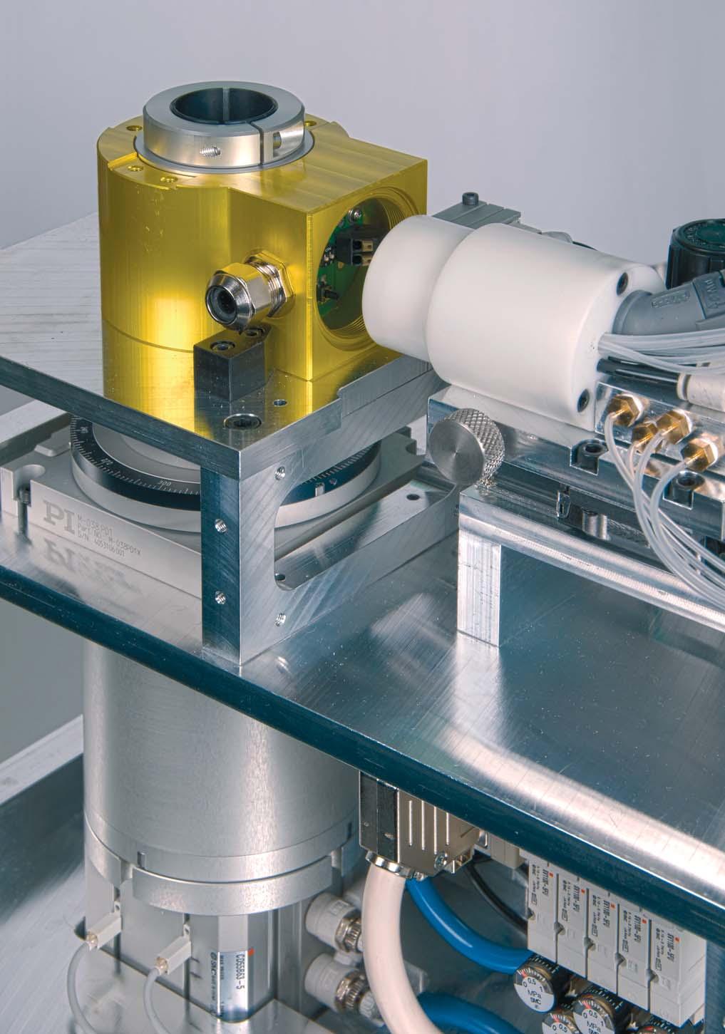
59 57


 and the behaviour of the analogue and digital outputs can be set by PC software without hardware variants.")


60 Products for Heavy Current Engineering Display units Multifunctional display units are used to monitor energy consumption in distribution facilities. They can replace numerous analogue indicators, have an integrated energy counter and partly network analysis functions. They may be connected to a PLC or control system via I/Os or bus connections (Modbus, Profibus, Ethernet, LON). Network configuration and connection parameters can be conveniently set via buttons or via PC software. Some versions permit customised parameterising of display data, e.g. the suppression of displays, priority displays or changing displays with interval control. Transducers The properties of multifunctional heavy current transducers can be completely programmed. They measure any variable of an electric network. The application (network configuration) and the behaviour of the analogue and digital outputs can be set by PC software without hardware variants. Measured value acquisition during operation is also supported via the programming or bus interface (Modbus, Profibus, Ethernet or LON). Programmable transducers are more resistant to interference in comparison with indicators and designed for more dynamic behaviour of the input signals. Unifunctional transducers are of an analogue design. They are customised to the required measuring task during the manufacturing process. The DC signal proportionate to the measured value can be used for visualising via analogue indicators or further PLC processing. Converters are available for all basic variables in the electric network Power quality The quality of energy available in electric networks is determined by the consumers connected. Their power consumption is often non-linear and influences the network quality negatively. This may impair the smooth operation of sensitive consumers (e.g. computers). The quality of network voltage which a power supplier has to provide is thus determined by international standards. But also energy consumers and equipment manufacturers must limit their feedback to the power system. For monitoring the compliance with standard values devices for temporary, mobile use and firm installation in the facility part to be monitored are available. Energy management Acquisition, analysis and optimising of the energy consumption and its allocation to generating cost centres is one of the central tasks of any company. To perceive the same on every level, we offer different product groups: 58 Active power meters (calibrateable) Summation stations. To record meter readings centrally via pulse inputs or via LON bus. Peak load optimisers: To avoid power peaks the current energy requirement is determined and optimised by direct consumer control. Energy Control System (ECS): The solution for energy data acquisition in the industrial environment. This system provides the data for cost centre allocation and the basis for consumer and load optimising.


61 Products of Process Control Engineering Temperature Temperature is the most measured variable in industry. However, the requirements of temperature measuring points vary from one application to the other. Camille Bauer offers extensive temperature transducers in the most varied designs for the analysis, conversion and transmission of temperature sensor signals. Head transmitters Head transmitters are directly installed in the connecting head of the temperature sensor. The sensor signal is converted into a ma signal, HART signal or Profibus PA signal directly on site. The head transmitters may be freely programmed and parameterised. Transmitter for top-hat rail assembly Intelligent terminals in 2-wire technology are suited to the installation in subdistributor systems close to the process or control cabinets. Their very small dimensions permit a space-saving installation. Temperature transmitters are directly assembled in the control cabinet and mainly use 4-wire technology. Measured variables and measuring ranges can be fully programmed which facilitates univeral usage and cost-saving stocks. All of our devices are galvanicly isolated, on principle, and also available in Ex-variants. Signal conversion As a link between the actual physical process and control engineering, we provide an extensive program for safe isolation, conversion and amplifying of signals, also for Ex-zones. Safety has the first priority also at this point. Power Supply Units Our power supply units provide 2-wire transducers with DC power and transmit the measuring signal 1:1 galvanicly separated to the measuring output. Isolation amplifiers Active isolation amplifiers have the task of galvanicly separating input signals from output signals, amplifying them and/or converting them to another level or type of signal (current or voltage). Different Ex-variants are also available. Passive isolators Passive DC signal isolators serve the galvanic isolation of a direct current signal which is transferred to a direct current or direct voltage signal depending on the device variant. They prevent the diversion of interference voltages and interference currents and solve earthing problems. Process Management Videographic recorders The vidographic recorders of the LINAX A300 family are paperless recorders of the latest generation. Their modular concept facilitates the flexible adaptation to the most varied needs. Depending on the type and design of the device users have up to 36 universal input channels at their disposal. Digital inputs and outputs, relay outputs, Ethernet interface, RS485 (Modbus) interface as well as transducer power supply are additional properties of the LINAX vidoegraphic recorders. Temperature control systems The goal of any control is to correct the change of the setpoint and the influence of interfering variables without overshooting and swinging. However, this is only possible if the controller behaves dynamically and is adjusted to the time behaviour of the controlling system. Our controllers and controller systems are the professional tool for optimum and high-quality control. A specially developed PDPI control action and optimising procedure corrects changes without overshooting and swinging. The integrated data loggers and histories register all relevant control process data in real time thus facilitating a detailed analysis of interferences. User-friendly software tools for commissioning (configuration, parameterising), remote diagnosis and remote maintenance support and simplify all relevant tasks. Our controller program comprises compact controllers, control modules for Simatic platforms, OEM control modules, software controllers (control algorithm) and modular temperature control systems. 59
KINAX 2W2 Programmable Transmitter for Angular Position
 Application The KINAX 2W2 (Figs. 2 and 3) converts the angular position of a shaft into a load independent direct current signal, proportional to the angular position. The unit is contact free and has
KINAX WT 717 Programmable Transmitter for Angular Position
 Ruggedized version Application The KINAX WT 717 (Fig. 1) converts the angular position of a shaft into a load-independent direct current signal, proportional to the angular position. The unit is contact
Rudder or propeller angular position transmitter KINAX WT720
 Description The is a robust, absolute angular position transmitter, which is particularly suitable for use in marine applications such as the detection of rudder or propeller positions. In contrast to
KINAX SR 719 Programmable Transmitter for Position Feedback
 Position transmitter with NAMUR valve fitting Application The position feedback transmitter KINAX SR 719 (Figs. 1 and 2) is used to measure and transmit linear displacement (stroke) on various types of
POSITION SENSORS TRANSMITTERS FOR ANGULAR POSITION AND INCLINATION TRANSMITTERS ROBUST RELIABLE FLEXIBLE
 POSITION SENSORS TRANSMITTERS FOR ANGULAR POSITION AND INCLINATION TRANSMITTERS ROBUST RELIABLE FLEXIBLE The correct position decides YOUR BENEFITS AT A GLANCE RELIABLE OPERATION DUE TO ROBUST DESIGN AND
Inclination Transmitters Heavy Duty
 High precision in all angle ranges Robust and compact design High resistance to aggressive media High degree of housing protection up to IP68 / IP69K Different output options Fast and easy assembly Easy
Technical data. General specifications. Linearity error ± 0.1 Electrical specifications Operating voltage U B
 Model Number SYNCHRON SERIELLES INTERFACE Features Very small housing Up to 32 Bit multiturn SSI interface Free of wear magnetic sampling High resolution and accuracy Description The ENA36IL series are
KINAX WT 707 Transmitter for angular position
 Ruggedized version pplication The KINX WT 707 (Figs. 1 to 6) converts the angular position of a shaft into a load-independent direct current signal, proportional to the angular position. The unit is contact
Technical data. General specifications. Linearity error ± 0.1 Functional safety related parameters MTTF d 700 a at 40 C Mission Time (T M ) L 10
 L 10") Model Number SYNCHRON SERIELLES INTERFACE Features Recessed hollow shaft SSI interface Up to Bit multiturn Free of wear magnetic sampling High resolution and accuracy Additionally push buttons for preset
Model Number SYNCHRON SERIELLES INTERFACE Features Recessed hollow shaft SSI interface Up to Bit multiturn Free of wear magnetic sampling High resolution and accuracy Additionally push buttons for preset
Technical data. General specifications V DC Power consumption P 0. 1 W Time delay before availability t v
 Model Number SYNCHRON SERIELLES INTERFACE Features Very small housing Up to 32 Bit multiturn SSI interface Free of wear magnetic sampling High resolution and accuracy Description The ENA36IL series are
Technical data. General specifications. Linearity error ± 0.1 Functional safety related parameters MTTF d 700 a at 40 C Mission Time (T M ) L 10
 L 10") Model Number SYNCHRON SERIELLES INTERFACE Features Solid shaft SSI interface Up to Bit multiturn Free of wear magnetic sampling High resolution and accuracy Additionally push buttons for preset function
Model Number SYNCHRON SERIELLES INTERFACE Features Solid shaft SSI interface Up to Bit multiturn Free of wear magnetic sampling High resolution and accuracy Additionally push buttons for preset function
Multiturn absolute encoder
 0102 Model Number SYNCHRON SERIELLES INTERFACE Features Up to 30 Bit multiturn ATEX approval IECEx approval Flameproof enclosure Removable connection cap Galvanically isolated RS 22 interface Description
Absolute encoders - SSI Solid shaft with clamping or synchro flange Optical multiturn encoders up to 14 bit ST / 16 bit MT
 Features Encoder multiturn / SSI Optical sensing method Resolution: max. singleturn 14 bit, multiturn 16 bit Clamping or synchro flange Electronic setting of zero point Counting direction input Available
Technical data. General specifications V DC No-load supply current I 0. typ. 50 ma Power consumption P 0
 Model Number SYNCHRON SERIELLES INTERFACE Cable pull rotary encoder with SSI interface Features Solid yet lightweight plastic construction Compact, slim design (the shaft of the mounted rotary encoder
Absolute encoders - SSI Solid shaft with clamping or synchro flange Optical multiturn encoders up to 14 bit ST / 16 bit MT
 Features Encoder multiturn / SSI Optical sensing method Resolution: max. singleturn 14 bit, multiturn 16 bit Clamping or synchro flange Electronic setting of zero point Counting direction input Available
Absolute encoders - SSI Solid shaft with clamping or synchro flange Optical multiturn encoders 18 bit ST / 12 bit MT
 Features High resolution encoder multiturn / SSI Optical sensing method Resolution: singleturn 18 bit, multiturn 12 bit Electronic setting of zero point Counting direction input Available with additional
Encoder - Absolut 2RMHF-SSI
 Absolute Encoder: Ø24 mm Hollow Shaft: Ø3 mm to ¼ Inch Singleturn or Multiturn SSI Interface Binary or Gray Code Preset of Zero Position Choice of Counting Direction IP-Rating: IP64 or IP67 Mechanical
Multiturn absolute encoder
 SYNCHRON SERIELLES INTERFACE Multiturn absolute encoder Model Number Features Industrial standard housing Ø58 mm 30 Bit multiturn Data transfer up to 2 MBaud Optically isolated RS 422 interface Recessed
Magnetic absolute multi-turn hollow shaft encoder BMMH MAGRES SSI
 Magnetic absolute multi-turn hollow shaft encoder BMMH MAGRES SSI features robust multi-turn encoder up to - 2 bit single-turn resolution - 3 bit multi-turn resolution miniature housing zero point programmable
Absolute encoders - SSI
 with through hollow shaft Features Encoder multiturn / SSI Optical sensing method Resolution: singleturn 14 bit, multiturn 12 bit Compact design Cost-efficient mounting High reliability by self-diagnostics
Incremental encoders Blind or through hollow shaft ø12 mm pulses per revolution
 Blind or through hollow shaft ø mm...5 pulses per revolution Features Encoder with blind or through hollow shaft ø mm Optical sensing method Max. 5 pulses per revolution Small profile depth Versatile mounting
Angular Position Transducers. inductive magnetoresistive optoelectronic
 Angular Position Transducers inductive magnetoresistive optoelectronic Angular Position Transducers with inductive, magnetoresistive or optoelectronic measuring systems Construction Measuring systems For
Multiturn absolute encoder
 SYNCHRON SERIELLES INTERFACE Multiturn absolute encoder Release date: 2016-07-12 16:14 Date of issue: 2016-07-12 t4917_eng.xml Model Number Features Industrial standard housing Ø58 mm 0 Bit multiturn Data
ABSOLUTE ROTARY ENCODER SSI
 Main Features - Compact and heavy-duty industrial model - Interface: Synchronous-serial (RS422/485) - Housing: 58 mm - Shaft: 6 or 10 mm - Resolution: Max. 25 Bit =,554,42 steps over 4,096 revolutions
Absolute encoders - SSI Shaft with clamping or synchro flange Optical multiturn encoders 14 bit ST / 12 bit MT
 Features Encoder multiturn / SSI Optical sensing Resolution: singleturn 14 bit, multiturn 12 bit Clamping or synchro flange Electronic setting of zero point Counting direction input Suitable for high positive,
LENORD. +BAUER... automates motion. GEL 2037 with heavy duty flange or tooth wheel adapter. Technical information Version General.
 GEL 2037 with heavy duty flange or tooth wheel adapter LENORD +BAUER... automates motion. Technical information Version 2014-07 General Multiturn absolute rotary encoders with a resolution of up to 25
Magnetic absolute single-turn encoder BMSH MAGRES parallel
 Magnetic absolute single-turn encoder BMSH MAGRES parallel features robust single-turn encoder up to 9 bit parallel interface miniature housing zero-point programmable general data voltage supply 5 VDC
Magnetic absolute encoder GEL 2035 Serial interface (SSI), 24 Bit
, 24 Bit") Magnetic absolute encoder GEL 2035 Serial interface (SSI), 24 Bit Technical information Version 03.09 Resolution: Precision: 0.8 Signal pattern: Singleturn (ST): Multiturn (MT): up to 24 Bit SSI and SSI
Magnetic absolute encoder GEL 2035 Serial interface (SSI), 24 Bit Technical information Version 03.09 Resolution: Precision: 0.8 Signal pattern: Singleturn (ST): Multiturn (MT): up to 24 Bit SSI and SSI
Absolute encoders - SSI EX approval ATEX EEx d IIC T6 Optical single and multiturn encoders 14 bit ST / 12 bit MT
 Features Encoder single- or multiturn / SSI / ATEX Optical sensing Resolution: singleturn 14 bit, multiturn 12 bit Clamping flange with shaft ø10 mm Explosion protection per EEx d IIC T6 Area of application:
ABSOLUTE ROTARY ENCODER MULTI-TURN BIT PARALLEL
 Main Features - Compact and heavy-duty industrial model - Interface: Bit-parallel, push pull ΠShort circuit proof - Housing: 58 mm - Shaft: 6 or 10 mm - Resolution: Max. 25 Bit =,554,42 steps over 4,096
ABSOLUTE ROTARY ENCODER SSI
 Main Features - Compact and heavy-duty industrial model - Interface: Synchronous-serial (RS 422) - Housing: 58 mm - Shaft: 6 or 10 mm - Hollow shaft 12 mm - Blind hollow shaft 15 mm - Max. 65,56 steps
Incremental encoders Redundant sensing, isolated blind hollow shaft ø mm, cone shaft ø17 mm pulses per revolution
 Features Robust, compact housing Two bearings with large distance, one at each end High shaft load up to 450 N Shock resistant up to 250 g Shaft insulation up to 2.8 kv Highest operating speed 10000 rpm
Magnetic absolute rotary encoder GEL 235 Singleturn, Multiturn up to 28 bits (SSI)
") Magnetic absolute rotary encoder GEL 25 Singleturn, Multiturn up to 28 bits (SSI) Technical information version 09.06 Unique Nonius-evaluation Measuring principle: magnetic, high resolution Evaluation:
Magnetic absolute rotary encoder GEL 25 Singleturn, Multiturn up to 28 bits (SSI) Technical information version 09.06 Unique Nonius-evaluation Measuring principle: magnetic, high resolution Evaluation:
Oil & Gas / Heavy Industry Type 2REX-A-NA-SSI
 Oil & Gas / Heavy Industry Type 2REX-A-NA-SSI EN 60079 Electrical Specifications Encoder Type: Singleturn Resolution: Number of Revolutions: Supply Voltage: Typical Current Consumption: Accuracy: ± 0,35ᴼ
Absolute Rotary Encoder EXAG Explosion Proof. Canopen
 Main Features - Approval: II 2 G/D EEx d II C T6 - Heavy-duty industrial model - Interface: CAN - Protocol: - Max. 65536 steps per revolution (16 Bit) - Max. 16384 revolutions (14 Bit) - Code: Binary Programmable
Technical data. General specifications. Measurement range min max. 360
 Model Number Features Very small housing High climatic resistance 12 Bit singleturn Analog output Surge and reverse polarity protection Description This absolute rotary encoder with internal magnetic sampling
LENORD. +BAUER... automates motion. Magnetic absolute rotary encoder GEL 2037 with heavy duty flange or tooth wheel adapter
 Magnetic absolute rotary encoder GEL 2037 with heavy duty flange or tooth wheel adapter LENORD +BAUER... automates motion. Technical information Version 01.12 General Multiturn absolute rotary encoders
Angular Position Transducers
 Angular Position Transducers Angular Position Transducers Construction Measuring systems For measuring angular positions and converting them into electrical signals for teletransmission purposes, either
ABSOLUTE ROTARY ENCODER DEVICE NET
 Main Features - Compact and heavy-duty industrial model - Certified: By ODVA - Interface: Device Net - Housing: 58 mm - Full or hollow shaft: 6 or 0 mm / 5 mm - Max. 6556 steps per revolution (6 Bit) -
KINAX 3W2 Transmitter for angular position
 KINX 3W2 For installation KINX 3W2 is a compact transmitter for angular position for installation in devices and apparatus. Due to its unique capacitive measuring principle, it acquires the angular position
ABSOLUTE ROTARY ENCODER SSI
 Main Features - Compact and heavy-duty industrial model - Interface: Synchronous -serial (RS 422) - Housing: 58 mm - Shaft: 6 or 10 mm - Hollow shaft 12 mm - Blind hollow shaft 15 mm - Max. 65,56 steps
Incremental encoders With blind or through hollow shaft pulses per revolution programmable
 Features Size mm Precise optical sensing Output signal level programmable (TTL or HTL) Blind or through hollow shaft, ø8 15 mm Connection axial, radial or tangential Pulses per revolution 1...65536, programmable
Absolute Rotary Encoder EXAG Explosion Proof. Device Net
 Main Features - Approval: II 2 G/D EEx d II C T6 - Heavy-duty industrial model - Interface: - Max. 65536 steps per revolution (16 Bit) - Max. 16384 revolutions (14 Bit) - Code: Binary Programmable Parameters
XXXX e. X d.. X X X a
 The Heavy Duty incremental encoder type 0H boasts a high degree of ruggedness in a very compact design. Its special construction makes it perfect for all applications in very harsh environments. / RoHS
Incremental encoders Blind hollow shaft or cone shaft pulses per revolution
 Features TTL output driver for cable length up to 550 m Very high resistance to shock and vibrations Hybrid bearing for extended service life Shaft insulation up to.8 kv Large terminal box, turn by 80
DATASHEET ABSOLUTE MAGNETIC ROTARY ENCODER SSI
 Robust rotary sensor based on reliable magnetic technology. Stainless steel housing capable to withstand extreme environmental conditions. Ideal suited for outdoor applications. Sturdy ball bearings for
DRS61: Incremental encoders, number of lines and zero pulse width freely programmable DRS60: Incremental Encoders with Zero-Pulse-Teach
 NEW DRS: Incremental encoders, number of lines and zero pulse width freely programmable DRS: s with Zero-Pulse-Teach Further highlights of this generation of encoders: Simple zero-pulse-teach by pressing
Absolute Encoders - Singleturn
 The Sendix 5853 and Sendix 5873 singleturn encoders with SSI or BiSS interface and optical sensor technology can achieve a resolution of max. 7 bits. These encoders are also available with an optional
Online data sheet AFS60A-BJPA AFS/AFM60 SSI ABSOLUTE ENCODERS
 Online data sheet FS0-JP FS/FM0 SSI FS0-JP FS/FM0 SSI C D E F H I J K L M N O P Q R S T Ordering information Type Part no. FS0-JP 09 Other models and accessories www.sick.com/fs_fm0_ssi Illustration may
Rotary encoders. absolute / optical. Bright ideas in the measurement of rotation: robust, precise, versatile.
 Rotary encoders absolute / optical right ideas in the measurement of rotation: robust, precise, versatile. Absolute encoder WK02/1 Hollow shaft WK02/1 - robust single-turn angle encoder with through hollow
MHAD 50 - HDmag. Features
 Magnetic sensing, hollow shaft 30 mm MHAD 50 with cable Features Absolute encoder with magnetic sensing and without bearings Absolute resolution max. 16 bit singleturn Additional incremental signals Robust
Lexium integrated drives
 Description ILp for CANopen, PROFIBUS DP, RS ILA with AC synchronous servo motor Description ILA comprise control electronics with a fieldbus interface for CANopen DS, PROFIBUS DP or RS and an AC synchronous
Material: Weight: Shaft Loads:
 Absolute Encoder Type SCA36NA-SSI Absolute Encoder - Ø 36 mm Shaft - Ø 6 mm Singleturn or Multiturn SSI Interface Binary or Gray Code Preset of Zero Position Choice of Counting Direction Enclosure Rating
Online data sheet AFS60E-S1AA AFS/AFM60 SSI ABSOLUTE ENCODERS
 Online data sheet FS0E-S0009 FS/FM0 SSI SOLUTE ENCODERS FS0E-S0009 FS/FM0 SSI SOLUTE ENCODERS C D E F Ordering information Type Part no. FS0E-S0009 0 Other models and accessories www.sick.com/fs_fm0_ssi
Absolute multi-turn hollow shaft encoder BOMH Dignalizer SSI
 features high resolution multi-turn encoder up to - 8 bit single-turn - 8 bit multi-turn interface programmable permanent self-test reference point programmable general data voltage supply 5 VDC (05C)
ABSOLUTE ROTARY ENCODER CAN-BUS
 Main Features - Compact and heavy-duty industrial model - Interface: CAN according to CAL - Housing: 8 mm - Shaft: 6 or 0 mm - Resolution: Max. 2 Bit =,,2 steps over,096 revolutions - Code: Binary - EMC:
Absolute Encoders Multiturn
 Absolute Encoders Multiturn Functional Safety, optical The absolute multiturn encoders Sendix 5863 SIL and 5883 SIL are perfectly suited for use in safety-related applications up to SIL3 according to DIN
Incremental EX and Stainless Steel Encoders
 Incremental EX and Stainless Steel Encoders RX 70-TI / RX 71-TI (Stainless) RI 59 explosion-proof according to EX II 2 G/D EEX d IIC T6/T4 highest operating safety applications e.g. lacquering lines, surface
NOVOTURN Multiturn Sensor non-contacting. Series RSM-2800
 NOVOTURN Multiturn Sensor non-contacting Series RSM-2800 Special features Non-contacting, magnetic Long life Electrical range 720 up to 5760 in 360 -steps available (2 to 16 turns) True-Power-On System:
Absolute Encoders Multiturn
 The Sendix F36 multiturn with the patented Intelligent Scan Technology is an optical multiturn encoder in miniature format, without gears and with 00% insensitivity to magnetic fields. With a size of just
Absolute Encoders - Singleturn
 The Sendix 5 and Sendix 7 singleturn encoders with SSI or BiSS-C interface and optical sensor technology can achieve a resolution of max. 7 bits. These encoders are also available with an optional SinCos
RoHS. High shaft load capacity. Shock / vibration resistant
 Due to their sturdy bearing construction in Safety Lock Design, the Sendix 5000 and 5020 offer high resistance against vibration and installation errors. The rugged housing, high protection level of up
Electrical data Units FVS 58, FHS 58. Operating voltage (PELV) [VDC] Current consumption at 24 VDC [ma] 85
![Electrical data Units FVS 58, FHS 58. Operating voltage (PELV) [VDC] Current consumption at 24 VDC [ma] 85](/thumbs/80/82459193.jpg "Electrical data Units FVS 58, FHS 58. Operating voltage (PELV) [VDC] Current consumption at 24 VDC [ma] 85") Parallel Singleturn bsolute Value Encoder Features 13-bit Singleturn High code change frequency Inputs for: - Selection of counting direction - Buffer memory (LTCH) - Multiplex operation (TRISTTE) Short-circuit
Parallel Singleturn bsolute Value Encoder Features 13-bit Singleturn High code change frequency Inputs for: - Selection of counting direction - Buffer memory (LTCH) - Multiplex operation (TRISTTE) Short-circuit
NOVOHALL Rotary Sensor non-contacting. Series RSC2800 digital SSI, SPI, Incremental
 NOVOHALL Rotary Sensor non-contacting Series RSC2800 digital SSI, SPI, Incremental The RSC 2800 sensor utilizes a contactless magnetic measurement technology to determine the measured angle. Unlike conventional
ABSOLUTE ROTARY ENCODER DEVICE NET
 Main Features - Compact and heavy-duty industrial model - Interface: CAN according to Device Net - Housing: 8 mm - Shaft: 6 or 0 mm - Resolution: Max. 2 Bit =,,2 steps over,096 revolutions - Code: Binary
LENORD. +BAUER... automates motion. GEL 295x Customer-specific precision encoder. Technical Information Version General information.
 GEL 95x Customer-specific precision encoder LENORD +BAUER... automates motion. Technical Information Version 04- General information Extremly robust rotary encoder with stainless steel housing for measuring
Online data sheet AFS60B-S4PA AFS/AFM60 SSI ABSOLUTE ENCODERS
 Online data sheet FS60-S4P032768 FS/FM60 SSI FS60-S4P032768 FS/FM60 SSI C D E F Ordering information Type Part no. FS60-S4P032768 1037483 Other models and accessories www.sick.com/fs_fm60_ssi Illustration
Absolute encoders - analog Blind hollow shaft ø12 mm Magnetic single- or multiturn encoders 12 bit ST / 16 bit MT
 Blind hollow shaft ø mm Magnetic single- or multiturn encoders bit ST / bit MT BMSH 8, BMMH 8 analog - MAGRES Features Encoder single- or multiturn / analog Magnetic sensing Resolution: singleturn bit,
Online data sheet AFM60B-S4PC AFS/AFM60 SSI ABSOLUTE ENCODERS
 Online data sheet FM60-S4PC032768 FS/FM60 SSI C D E F H I J K L M N O P Q R S T Ordering information Type Part no. FM60-S4PC032768 1037504 Other models and accessories www.sick.com/fs_fm60_ssi Illustration
ABSOLUTE ROTARY ENCODER SSI PROGRAMMABLE
 Main Features - Compact and heavy-duty industrial model - Interface: Synchronous-serial (RS422/485) - Housing: 58 mm - Shaft: 6 or 10 mm - Resolution: Max. 25 Bit =,554,42 steps over 4,096 revolutions
Incremental encoders With blind or through hollow shaft pulses per revolution programmable
 Features Size ø58 mm Precise optical sensing Output signal level programmable (TTL or HTL) Blind or through hollow shaft, ø8 15 mm Connection axial, radial or tangential Pulses per revolution 1...65536,
Incremental Encoder Model: FOI58
 Incremental Encoder Model: FI58 Document no. FI 188 BE Date: 1.01.201 Robust mechanical construction, high vibration and shock resistance 1 to 16,8 pulses/ revolution perating temperature - 0 C to + 85
Online data sheet. ACM60B-S1KE13x06 ACM60 ABSOLUTE ENCODERS
 Online data sheet ACM60B-S1KE1x06 ACM60 A B C D E F H I J K L M N O P Q R S T Illustration may differ Detailed technical data Performance Number of steps per revolution Number of revolutions Ordering information
SINEAX TV809, 1 channel Programmable Isolating Amplifier
 For electrically insulating, ampliflying and converting DC signals 0102 II (1) Ga II (1) Da Application The purpose of the isolating amplifi er SINEAX TV809 (Fig. 1) is to electrically insulate input and
Rotary Measurement Technology Incremental Encoders
 -20 to 60 C Temperature Shock/vibration resistant Short-circuit protection Reverse polarity protection High rotational speed Rugged Balanced, stainless-steel clamping rings, special bearing-shaft connection
ABSOLUTE MAGNETIC ROTARY ENCODER ANALOG
 High-resolution absolute encoder based on magnetic technology. Singleturn sensing based on 360 Hall effect technology. Multiturn sensing based on magnetic pulse counter. No batteries used. Main Features
Rotary Measuring Technology
 Our ATEX encoders now also carry approval for Dust Flameproof-enclosure type of construction with approval for Zone 1 and 21 ExII2GEExdIICT6 and ExII2DIP6xT85 C Shaft ø 12 mm One type for every situation:
Absolute Encoders Singleturn
 The absolute singleturn encoders Sendix 5853 SIL and 5873 SIL are perfectly suited for use in safety-related applications up to SIL3 according to DIN EN ISO 6800-5- or PLe to DIN EN ISO 3849. The extra
XXXX e. X d.. X X X a
 The Heavy uty incremental encoder type 0H boasts a high degree of ruggedness in a very compact design. Its special construction makes it perfect for all applications in very harsh environments. / RoHS
Data Sheet for Angle Sensors
 ETA25PM - R ETA25PM - F ETA25PM - TS 10 to 100-times longer life compared with multiturn potentiometers Free user programmable start and end position (electrical angle 10 up to 72000 ) Simple user programming
Rotary Measuring Technology
 SSI or parallel interface Highest shock resistance on the market ( 2500 m/s2, 6 ms acc. to DIN IEC 68-2-27) Divisions: up to 16384 (14 bits), singleturn Housing Ø 58 mm IP 66 Various options (e.g. LATCH,
Measurement and Sensor Systems with conception
 Measurement and Sensor Systems with conception Rope Length Transmitter Rope Length Transmitter Rope Length Transmitters were used for length and speed measurements of linear movement operations in several
Analog Universal Module HART for Zone 2 Series 9468/33
 > 8 channels can be adjusted individually as analog inputs or outputs > Intrinsically safe inputs/outputs Ex ia > For 0/4 20 ma + HART signals > Line fault monitoring per channel > Diagnostics based on
IXARC Incremental Encoder UCD-IPT M100-PRD. Interface Programmable Incremental. Configuration Tool UBIFAST Configuration Tool (Version 1.6.
 IXARC Incremental Encoder UCD-IPT00-08192-M100-PRD Interface Interface Programmable Incremental Programming Functions PPR (1-16384), Output, Counting Direction Configuration Tool UBIFAST Configuration
Series BC 58. Absolute Rotary Encoder Series BC 58
 Mechanical specifications Shaft diameter Shaft load 6 mm (synchro flange) 10 mm (clamping flange) 10/12 mm (blind hollow shaft) Series BC 58 E Absolute single- and multiturn rotary-encoder with solid shaft
Inductive Angle Sensor With Analog Output RI360P1-QR14-ELIU5X2
 Rectangular, plastic Many mounting possibilities P1-Ri-QR14 included in delivery Measuring range displayed via LED Immune to electromagnetic interference Resolution, 12-bit 4-wire, 15 30 VDC Analog output
Online data sheet AFS60E-S4AC AFS/AFM60 SSI ABSOLUTE ENCODERS
 Online data sheet FS60E-S4000256 FS/FM60 SSI FS60E-S4000256 FS/FM60 SSI D E F Ordering information Type Part no. FS60E-S4000256 1052119 Other models and accessories www.sick.com/fs_fm60_ssi Illustration
Online data sheet. DBS60E-TECJD1024 DBS60 Core INCREMENTAL ENCODERS
 Online data sheet DS60ETECJD1024 DS60 Core C D E F H I J K L M N O P Q R S T Ordering information Type Part no. DS60ETECJD1024 DS60ETECJD1024 Other models and accessories www.sick.com/ds60_core Illustration
Wind Direction Transmitter - compact - GMR, analogue output xxx xxx
 THE WORLD OF WEATHER DATA - THE WORLD OF WEATHER DATA - THE WORLD OF WEATHER DATA Instruction for Use 021488/06/09 Wind Direction Transmitter - compact - GMR, analogue output - 4.3129.60.xxx 4.3129.80.xxx
SALES SERVICE +358 (0)
") SALES SERVICE +358 (0)17 262 3555 info@econosto.fi ADCATROL ELECTRO-PNEUMATIC POSITIONERS PE 986 (ATEX) DESCRIPTION The ADCATROL PE986 positioner requires an input signal of 4 20 ma for proportional control
SALES SERVICE +358 (0)17 262 3555 info@econosto.fi ADCATROL ELECTRO-PNEUMATIC POSITIONERS PE 986 (ATEX) DESCRIPTION The ADCATROL PE986 positioner requires an input signal of 4 20 ma for proportional control
SINEAX TV 808, 1 channel Isolating Amplifier unipolar/bipolar
 For electrically insulating, amplifying and converting DC signals 0102 II (1) G Application The purpose of the isolating amplifi er SINEAX TV 808 (Fig. 1 and 2) is to electrically insulate input and output
Positioning drives DC motor, brushless Absolute multiturn position detection, Profibus-DP
 Features Positioning drive with worm gear bevel geared shaft Profibus-DP Brushless DC motor Absolute multiturn position detection Nominal power output 80 W inputs programmable Separate communication and
Online data sheet ACM36-L1K0-K01 ACS/ACM36 ABSOLUTE ENCODERS
 Online data sheet ACM36-L1K0-K01 ACS/ACM36 ACM36-L1K0-K01 ACS/ACM36 A B C D E F H I J K L M N O P Q R S T Illustration may differ Detailed technical data Performance Number of steps per revolution Number
Catalogue. Stepper Motors VRDM, ExRDM
 Catalogue Stepper Motors VRDM, ExRDM Stepper Motors Table of Contents -phase stepper motors Product description...................................... VRDM 6 Technical data........................................
Wind Direction Transmitter - compact - with serial output x0.x00
 THE WORLD OF WEATHER DATA - THE WORLD OF WEATHER DATA - THE WORLD OF WEATHER DATA Instruction for Use 021450/11/05 Wind Direction Transmitter - compact - with serial output - 4.3129.x0.x00 ADOLF THIES
n Measuring range ,02 N m to N m n Clockwise and counter-clockwise torque n Low linearity deviation of ± 0.05 % F.S.
 Precision Torque Sensor Non-contact transmission for rotating applications Optional measurement of angle and speed Model 8661 Code: Delivery: Warranty: 2-3 weeks 24 months Application The 8661 precision
Motor Encoders. With Motor encoders Series M - Optimal control of motor feedback -
 Motor Encoders With Motor encoders Series M - Optimal control of motor feedback - Hengstler supplies the new high-performance motor encoder series M for use with brushless servo motors and stepper motors.
Incremental encoders 6
 Incremental encoders ELECTRONIC GmbH Incremental encoders 6 6.1 Explanatory notes...6-3 6.2 Functional description...6-4 6.3 Applications...6-5 6.4 Assembly examples...6-6 6.5 Alternative designs...6-8
ABSOLUTE MAGNETIC ROTARY ENCODER ANALOG
 High-resolution absolute encoder via magnetic technology. Singleturn encoding based on 360 Hall effect technology. Multiturn encoding based on magnetic pulse counter. No batteries used. Main Features -
LENORD. +BAUER... automates motion. Magnetic incremental encoder GEL 293 for heavy duty applications. Technical Information Version 04.
 Magnetic incremental encoder GEL 293 for heavy duty applications LENORD +BAUER... automates motion. Technical Information Version 04.14 General information High-resolution magnetic incremental rotary encoder