University of Technology, Jamaica School of Engineering. Electrical Workshop Notes On Electrical components
|
|
|
- Cory Walker
- 6 years ago
- Views:
Transcription
1 University of Technology, Jamaica School of Engineering Electrical Workshop Notes On Electrical components
2 Resistors Resistors are fundamental components in electronic circuits. A resistor is constructed to have a specific amount of resistance to current flow. The range of resistors may be from less than one ohm to well over 20 million ohms. Fixed resistors have a single value of resistance, but variable resistors can provide different values of resistance.
3 Resistors Resistors are rated by their value of resistance and the power they can safely dissipate. Every resistor has a power rating. The power rating is to a large degree, determined by its size. The greater the surface area, the more power it can dissipate. Power ratings of resistors vary from less than one tenth of a watt to many hundreds of watts.
4 Resistors Resistor tolerance is a measure of the resistor s variation from the specified value. Resistor tolerance is expressed as a percentage of its nominal value. Typical resistor tolerances are 1% and 5%, with tighter-tolerance resistors being somewhat more expensive. Resistors with tolerances lower than 2% are called precision resistors.
5 Resistance All materials exhibit electrical resistance The resistance of a material of uniform cross section is determined by: Material Length Cross-sectional area Temperature
6 Material Each material has a unique molecular structure Each material will react differently to pressures to establish a current through it Each material has a characteristic property called resistivity The symbol for resistivity is ρ (rho)
7 Length and Area The resistance R of a material of uniform cross-section is: Directly proportional to its length (longer, more resistance) Inversely proportional to its crosssectional area (bigger area, smaller resistance)
8 Resistivity Relationship R = ρl/a The resistance of a material of uniform cross-section is given by: R = ρl/a Where R = resistance (Ω) ρ = resistivity (Ω.m) l = length (cm) A = area (m 2 )
9 Resistor Technology There are four major classes of fixed resistor technology (see following slides): Carbon-composition Film resistors Wirewound resistors Surface-mount technology
10 Resistor Technology Carbon-composition Film resistors
11 Resistor Technology Wirewound resistors Surface-mount technology
12 Resistor Colour Code The resistor may have three, four or five coloured bands The first three bands represent the resistance value The fourth band represents the tolerance (accuracy) The fifth band (if present) represents a reliability factor
13 Resistor Color Code (3-4 Band) Since resistors are physically small, it is impractical to print the value of the resistor on it. Manufacturers mark resistors with three to five colored bands to indicate its value. Three- or four-band resistors can be interpreted by the following procedure: The first two bands represent the first two digits of the resistance value Multiply the digits obtained in step one by the multiplier value If a fourth band is present, it indicates the tolerance. If there is no fourth band, the tolerance is ±20%
14 Resistor Color Codes Bad beer rots our young guts but vodka goes well! Band Type Color Value Multiplier Tolerance Digit/Multiplier Black Digit/Multiplier Brown Digit/Multiplier Red Digit/Multiplier Orange Digit/Multiplier Yellow Digit/Multiplier Green Digit/Multiplier Blue Digit/Multiplier Violet Digit/Multiplier Gray Digit/Multiplier White Multiplier/Tolerance Gold ±5% Multiplier/Tolerance Silver ±10% Multiplier/Tolerance None - - ±20%
15 Variable Resistors Sometimes it is desirable to change the value of a resistor installed in a circuit. The resistance of a variable resistance is controlled by turning a knob, rotating a screw, or moving a slider. Two major classes of variable resistors are: Rheostats Potentiometers
16 Resistors Surface-mount resistor markings: Many surface-mounted components have no visible markings and must be measured with test equipment to determine their value. Some manufacturers indicate the value of a surface mount resistor with a numerical code. The first digit or digits indicate the value of the resistor and the last digit indicates the multiplier. A code of 103 would indicate a value of 10,000 ohms.

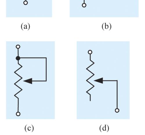
17 Resistor Symbols
18 Resistor Colour Code The resistor may have three, four or five coloured bands The first three bands represent the resistance value The fourth band represents the tolerance (accuracy) The fifth band (if present) represents a reliability factor
19 Resistor Colour Code Each of the first three bands represents a single digit number The resistance value is found by forming a two digit number from the first two bands The two digit number is then multiplied by a power of ten given by the digit representing the third band The resistor tolerance is given by the fourth band
20 Learning the Code Step 1: Memorise the colour values: 0 Black Multipliers 1 Brown 0.1 Gold 2 Red 0.01 Silver 3 Orange 4 Yellow Tolerance 5 Green 5% Gold 6 Blue 10% Silver 7 Violet 20% No band 8 9 Grey White
21 Learning the Code Step 2: The first three bands represent the resistance value Each of the first three bands represents a single digit number The third band digit is the power of ten that multiplies the number formed by the first two digits The third band represents the number of zeros following the first two digits
22 Sample Calculation Say the first three coloured bands are brown, red, orange The digits are: 1 = brown 2 = red 3 = orange (3 zeros) The value is 12x10 3 = 12,000Ω
23 Learning the Code Step 3: The fourth band gives the tolerance In this example the fourth band is silver 10% = silver
24 Learning the Code Thus the resistor in this example has a value of 12,000Ω (12KΩ) and a tolerance of 10%
25 Resistance
26 Capacitors A capacitor is a basic electronic component that stores electrical energy in the form of an electrostatic charge. The operation of nearly every electronic The operation of nearly every electronic system depends upon capacitors.
27 Inductors An inductor is also a fundamental electronic component, sometimes referred to as a coil. It consists of a spiraled or coiled wire. The inductor stores electrical energy in the form of an electromagnetic field.
28 Transformers A transformer is basically two or more coils whose electromagnetic fields interact. Transformers are used to increase or decrease alternating voltages.
29 Switches Switches are yet another group of basic electrical devices. Switches break (open) or make (close) circuit connections. See below and following slide for examples.
30 Switches
31 Basic Switch Operation The pole in a switch is the moveable part. The term throw refers to how many circuits are opened or closed during the switching operation. A double-throw switch opens or closes two circuits on each pole. Basic switch types include SPST, SPDT, DPST, DPDT, etc. Some switches do not maintain contacts when operated and are called momentary-contact switches.
32 Relays Relays are electromagnetically operated switches. They are used extensively in electrical systems, especially industrial systems. Relays are used for motor control circuits, circuits to protect workers, switching circuits, and power switching.
33 Transistors and Diodes Transistors and Diodes are solid-state devices or semiconductors. They are used in many electronic devices, including amplifiers, computers, and industrial controls. Diodes are used to alter information signals, convert AC current into DC current, and as protective devices and switches.
34 Single Way Switching
35 Two Way Switching

36 THANK YOU FOR YOUR ATTENTION!!
DEPARTMENT OF ELECTRONIC ENGINEERING ELECTRONIC WORKSHOP # 03. Resistors
 MEHRAN UNIVERSITY OF ENGINEERING AND TECHNOLOGY, JAMSHORO DEPARTMENT OF ELECTRONIC ENGINEERING ELECTRONIC WORKSHOP # 03 Resistors Roll. No: Checked by: Date: Grade: Object: To become familiar with resistors,
2007 The McGraw-Hill Companies, Inc. All rights reserved.
 Chapter 2 Resistors Topics Covered in Chapter 2 2-1: Types of Resistors 2-2: Resistor Color Coding 2-3: Variable Resistors 2-4: Rheostats and Potentiometers 2-5: Power Ratings of Resistors 2-6: Resistor
6. Resistor Colour Code
 6. Resistor Colour Code We saw in the previous tutorial that there are many different types of Resistors available and that they can be used in both electrical and electronic circuits to control the flow
Circuit LED 1 LED 2 A on or off on or off B on or off on or off C on or off on or off
 Cornerstone Electronics Technology and Robotics Week 8 Chapter 3, Introduction to Basic Electrical Circuit Materials Continued Administration: o Prayer o Turn in quiz Review LED s: o Wire the following
BASIC ELECTRICITY - PART 3
 Reading 3 Ron Bertrand VK2DQ http://www.radioelectronicschool.com BASIC ELECTRICITY - PART 3 MORE ON RESISTANCE As discussed briefly in Basic Electricity Part II, resistance is the opposition to current
Electronic component
 Electronic component Electronic component: An electronic component is any basic discrete device or physical entity in an electronic system used to affect electrons or their associated fields. 2 TYPES OF
Techo notes. Resistors. Composition Resistors. Resistor Symbol
 Resistors Techo notes Resistors (R), are the most commonly used of all electronic components, to the point where they are almost taken for granted. There are many different resistor types available with
ENGINEERING COUNCIL CERTIFICATE LEVEL ENGINEERING SCIENCE C103
 ENGINEERING COUNCIL CERTIFICATE LEVEL ENGINEERING SCIENCE C03 TUTORIAL 4 ELECTRICAL RESISTANCE On completion of this tutorial you should be able to do the following. Explain resistance and resistors. Explain
LABORATORY Experiment 1
 LABORATORY Experiment 1 Resistivity Measurement, Resistors and Ohm s Law 1. Objectives To measure the resistance of conductors, insulators and semiconductor and calculate the resistivity of a copper wire.
ELECTRONICS An Introduction
 BHAGAVATULA CHARITABLE TRUST ELECTRONICS An Introduction ఎల - ప చయ BCT-RHS BCT Farm Complex Haripuram Rambilli Mandal Visakhapatnam, AP 531061 Phone +91 (8924) 253 770 Fax +91 (8924) 253 780 Author: Sriram
Introduction. Inductors in AC Circuits.
 Module 3 AC Theory What you ll learn in Module 3. Section 3.1 Electromagnetic Induction. Magnetic Fields around Conductors. The Solenoid. Section 3.2 Inductance & Back e.m.f. The Unit of Inductance. Factors
Chap. 5 Electronic Components and Sensing Devices
 1 Chap. 5 Electronic Components and Sensing Devices Today, practically all mechanical devices contain some sort of electronic components. The function of a product often relies on the integration of mechanical
Electrical Functions Notes
 Electrical Functions Notes Electrical Function An electrical function is the role that a component plays in the control or transformation of electric current. Power Supplies Power supply is the electrical
Component Identification
 Generic Skills for Microelectronic Engineers Component Identification AIM: To be able to identify common electronic components used in miniature and medium power applications. Methods of labelling, range
Kirchoff s Current Law
 Kirchoff s Current Law If you have water flowing into and out of a junction of several pipes, water flowing into the junction must equal water flowing out. The same applies to electric currents. I I 3.
Pre-Laboratory Assignment
 Measurement of Electrical Resistance and Ohm's Law PreLaboratory Assignment Read carefully the entire description of the laboratory and answer the following questions based upon the material contained
Resistance. Department of Physics & Astronomy Texas Christian University, Fort Worth, TX. April 23, 2013
 Resistance Department of Physics & Astronomy Texas Christian University, Fort Worth, TX April 23, 2013 1 Introduction Electrical resistance is a measure of how much an object opposes (or resists) the flow
Workshop Part Identification Lecture N I A G A R A C O L L E G E T E C H N O L O G Y D E P T.
 Workshop Part Identification Lecture N I A G A R A C O L L E G E T E C H N O L O G Y D E P T. Identifying Resistors Resistors can be either fixed or variable. The variable kind are called potentiometers
Voltage, Current, and Resistance. Objectives
 Voltage, Current, and Resistance ELEC 111 Objectives Define voltage and discuss its characteristics Define current and discuss its characteristics Define resistance and discuss its characteristics 21 January
Electrical Components and their Functions
 Electrical Components and their Functions Electricity & Electronics All electrical appliances and electronic devices depend on electrical circuits. The main difference between electricity & electronics
Main improvements are increased number of LEDs and therefore better temperature indication with one Celsius degree increments.
 LED Thermometer V2 (Fahrenheit/Celsius/±1 ) PART NO. 2244754 After completing this great starter kit, users will have a nice interactive LED thermometer. You will learn one principle how temperature can
DC Circuits, Ohm's Law and Multimeters Physics 246
 DC Circuits, Ohm's Law and Multimeters Physics 246 Theory: In this lab we will learn the use of multimeters, verify Ohm s law, and study series and parallel combinations of resistors and capacitors. For
EET140/3 ELECTRIC CIRCUIT I
 SCHOOL OF ELECTRICAL SYSTEM ENGINEERING UNIVERSITI MALAYSIA PERLIS EET140/3 ELECTRIC CIRCUIT I MODULE 1 PART I: INTRODUCTION TO BASIC LABORATORY EQUIPMENT PART II: OHM S LAW PART III: SERIES PARALEL CIRCUIT
A.M. WEDNESDAY, 19 May minutes
 Candidate Name Centre Number Candidate Number 0 GCSE 293/02 ELECTRONICS MODULE TEST E1 HIGHER TIER AM WEDNESDAY, 19 May 2010 45 minutes For s use Total Mark ADDITIONAL MATERIALS In addition to this examination
SPINE ROAD HIGH SCHOOL TECHNOLOGY TEST 2 GRADE 9 SEPTEMBER 2017 EXAMINER: MRS N GOVENDER MODERATOR: MR LUKIE TIME: 1 HOUR 30 MINUTES INSTRUCTIONS
 SPINE ROAD HIGH SCHOOL TECHNOLOGY TEST 2 GRADE 9 SEPTEMBER 2017 EXAMINER: MRS N GOVENDER MODERATOR: MR LUKIE TIME: 1 HOUR 30 MINUTES INSTRUCTIONS 1. Answer all questions 2. Rule off after each question.
Electronics & Control
 Electronics & Control Analogue Electronics Introduction By the end of this unit you should be able to: Know the difference between a series and parallel circuit Measure voltage in a series circuit Measure
Circuit Components Lesson 4 From: Emergency Management Ontario
 4.1 Amplifier Fundamentals The role of a amplifier is to produce an output which is an enlarged reproduction of the features of the signal fed into the input. The increase in signal by an amplifier is
12V Dimmer Kit, version 2
 12V Dimmer Kit, version 2 User Manual Description The 12V Dimmer Kit V2 is an especially efficient PWM (pulse-width modulation) controller for 12V loads up to 60 watts. It features a single dial control
Technology and Design Unit 2: Systems and Control Element 1: Electronic and Microelectronic Control Systems
 New Specification Centre Number 71 Candidate Number General Certificate of Secondary Education 2011 Technology and Design Unit 2: Systems and Control Element 1: Electronic and Microelectronic Control Systems
Electronics Technology and Robotics I Week 5 Resistors and Potentiometers
 Electronics Technology and Robotics I Week 5 Resistors and Potentiometers Administration: o Prayer o Turn in quiz o Using two switches, design a circuit that correspond to an AND gate. Resistors: o Function:
3.5 Types of Resistors
 7 Chapter 3 Resistance IN-PROCESS LERNING CHECK 4 Explain what is meant by the terms positive temperature coefficient and negative temperature coefficient. To which category does aluminum belong? (nswers
Inductors and Transformers
 MEHRAN UNIVERSITY OF ENGINEERING AND TECHNOLOGY, JAMSHORO DEPARTMENT OF ELECTRONIC ENGINEERING ELECTRONIC WORKSHOP # 05 Inductors and Transformers Roll. No: Checked by: Date: Grade: Object: To become familiar
The Discussion of this exercise covers the following points:
 Exercise 5 Resistance and Ohm s Law EXERCISE OBJECTIVE When you have completed this exercise, you will be familiar with the notion of resistance, and know how to measure this parameter using an ohmmeter.
VCE VET ELECTROTECHNOLOGY
 Victorian Certificate of Education 2010 SUPERVISOR TO ATTACH PROCESSING LABEL HERE STUDENT NUMBER Letter Figures Words VCE VET ELECTROTECHNOLOGY Written examination Thursday 4 November 2010 Reading time:
BASIC ELECTRONICS PROF. T.S. NATARAJAN DEPT OF PHYSICS IIT MADRAS LECTURE-2 ELECTRONIC DEVICES -1 RESISTOR, IDEAL SOURCE VOLTAGE & CAPACITOR
 BASIC ELECTRONICS PROF. T.S. NATARAJAN DEPT OF PHYSICS IIT MADRAS LECTURE-2 ELECTRONIC DEVICES -1 RESISTOR, IDEAL SOURCE VOLTAGE & CAPACITOR In the last lecture we saw the importance of learning about
Control Unit Series 8208
 > Installation of various components such as Snap action switch Potentiometer Relay Time relay Diodes Fuses Resistors www.stahl.de 01776E00 Components of various functions such as diodes, resistors, fuses
AC/DC ELECTRONICS LABORATORY
 Includes Teacher's Notes and Typical Experiment Results Instruction Manual and Experiment Guide for the PASCO scientific Model EM-8656 012-05892A 1/96 AC/DC ELECTRONICS LABORATORY 1995 PASCO scientific
Lab 3 DC CIRCUITS AND OHM'S LAW
 43 Name Date Partners Lab 3 DC CIRCUITS AND OHM'S LAW AMPS + - VOLTS OBJECTIVES To learn to apply the concept of potential difference (voltage) to explain the action of a battery in a circuit. To understand
UNIVERSITY OF NORTH CAROLINA AT CHARLOTTE Department of Electrical and Computer Engineering
 UNIVERSITY OF NORTH CAROLINA AT CHARLOTTE Department of Electrical and Computer Engineering EXPERIMENT 2 BASIC CIRCUIT ELEMENTS OBJECTIVES The purpose of this experiment is to familiarize the student with
2 Resistors. Air Washington Electronics Direct Current. Page 1 of 41
 2 Resistors This work is licensed under the Creative Commons Attribution 3.0 Unported License. To view a copy of this license, visit http://creativecommons.org/licenses/by/3.0/. Air Washington is an equal
Basic Electronics for Model Railroaders By Gene Jameson NMRA Convention, Kansas City MO., August 5 12, 2018
 Basic Electronics for Model Railroaders By Gene Jameson NMRA Convention, Kansas City MO., August 5 12, 2018 Please turn off your cell phones. If it rings I will ask you to leave the room and I will NOT
Electronic Components (Elements)
") Lecture_3 Electronic Components (Elements) Instructor: IBRAHIM ABU-ISBEIH 25 July 2011 Reverse Engineering 1 Objectives: After completing this class, you will be able to identify the most commonly used
Lecture_3 Electronic Components (Elements) Instructor: IBRAHIM ABU-ISBEIH 25 July 2011 Reverse Engineering 1 Objectives: After completing this class, you will be able to identify the most commonly used
Embedded Systems Analog Electronics
 Embedded Systems Analog Electronics Units physical units = length [meter], mass [kilogram], time [second] force - [Newton]: kg m/s 2 (F=ma) torque - [N m] energy - [joule]: 1N acting through distance of
EET 150 Introduction to EET Lab Activity 1 Resistor Color Codes and Resistor Value Measurement
 Required Parts, Software and Equipment Parts 20 assorted 1/4 watt resistors 5% tolerance Equipment Required Solderless Experimenters' Board Digital Multimeter Optional Alligator clip leads hookup wire
FCC Technician License Course
 FCC Technician License Course 2014-2018 FCC Element 2 Technician Class Question Pool Presented by: Tamiami Amateur Radio Club (TARC) WELCOME To the SECOND of 4, 3-hour classes presented by TARC to prepare
ELECTRIC CIRCUITS AND ELECTRONICS
 Circuitos eléctricos y electrónicos ELECTRIC CIRCUITS AND ELECTRONICS Technology, programming and robotics II Electric Circuitos circuits eléctricos and y electronics electrónicos AN ELECTRICAL CIRCUIT
II. Experimental Procedure
 Ph 122 July 27, 2006 Ohm's Law http://www.physics.sfsu.edu/~manuals/ph122/ I. Theory In this lab we will make detailed measurements on one resistor to see if it obeys Ohm's law. We will also verify the
Embedded Control. Week 1 (6/29/11)
") Embedded Control Week 1 (6/29/11) Week 1 15:00 Lecture Circuit theory, terminology Overview of elementary circuit components Reading circuit diagrams 16:00 Lab NXT GPIO with HiTechnic sensor expansion
Embedded Control Week 1 (6/29/11) Week 1 15:00 Lecture Circuit theory, terminology Overview of elementary circuit components Reading circuit diagrams 16:00 Lab NXT GPIO with HiTechnic sensor expansion
DC Circuits. Date: Introduction
 Group # Date: Names: DC Circuits Introduction In this experiment you will examine how to make simple DC measurements that involve current, voltage, and resistance. The current I through a resistor R with
Electronic Components
 Engineering Project (1) Lecture_2 Electronic Components (Elements) Instructor: Eng. IBRAHIM ABU-ISBEIH 6 March 2012 Eng. Ibrahim Abu-Isbeih 1 Objectives: After completing this class, you will be able to
University of Jordan School of Engineering Electrical Engineering Department. EE 219 Electrical Circuits Lab
 University of Jordan School of Engineering Electrical Engineering Department EE 219 Electrical Circuits Lab EXPERIMENT 4 TRANSIENT ANALYSIS Prepared by: Dr. Mohammed Hawa EXPERIMENT 4 TRANSIENT ANALYSIS
Tutorial Using a multimeter
 Tutorial Using a multimeter The multimeter You might have already seen or worked with a multimeter. It is an electronic measuring device that combines several instruments such as the voltmeter (to measure
UNIT E1 (Paper version of on-screen assessment) A.M. WEDNESDAY, 8 June hour
 A.M. WEDNESDAY, 8 June hour") Candidate Name GCSE 46/0 Centre Number Candidate Number 0 ELECTRONICS UNIT E (Paper version of on-screen assessment) A.M. WEDNESDAY, 8 June 20 hour For s use 46 0000 Total Mark ADDITIONAL MATERIALS Information
Candidate Name GCSE 46/0 Centre Number Candidate Number 0 ELECTRONICS UNIT E (Paper version of on-screen assessment) A.M. WEDNESDAY, 8 June 20 hour For s use 46 0000 Total Mark ADDITIONAL MATERIALS Information
Ohm's Law and DC Circuits
 Physics Lab II Ohm s Law Name: Partner: Partner: Partner: Ohm's Law and DC Circuits EQUIPMENT NEEDED: Circuits Experiment Board Two Dcell Batteries Wire leads Multimeter 100, 330, 560, 1k, 10k, 100k, 220k
OHM'S LAW AND RESISTANCE NETWORKS OBJECT
 17 E7 E7.1 OHM'S LAW AND RESISTANCE NETWORKS OBJECT The objects of this experiment are to determine the voltage-current relationship for a resistor and to verify the series and parallel resistance formulae.
Lab 1: Basic Lab Equipment and Measurements
 Abstract: Lab 1: Basic Lab Equipment and Measurements This lab exercise introduces the basic measurement instruments that will be used throughout the course. These instruments include multimeters, oscilloscopes,
DC CIRCUITS AND OHM'S LAW
 July 15, 2008 DC Circuits and Ohm s Law 1 Name Date Partners DC CIRCUITS AND OHM'S LAW AMPS - VOLTS OBJECTIVES OVERVIEW To learn to apply the concept of potential difference (voltage) to explain the action
Aim: To learn the resistor color codes and building a circuit on a BreadBoard. Equipment required: Resistances, millimeter, power supply
 Understanding the different components Aim: To learn the resistor color codes and building a circuit on a BreadBoard Equipment required: Resistances, millimeter, power supply Resistors are color coded
Lesson 3: Electronics & Circuits
 Lesson 3: Electronics & Circuits Preparation for Amateur Radio Technician Class Exam Topics Review Ohm s Law Energy & Power Circuits Inductors & Inductance Capacitors & Capacitance Analog vs Digital Exam
National Quali cations Date of birth Scottish candidate number
 N5FOR OFFICIAL USE X860/75/01 National Quali cations 2018 Mark Practical Electronics WEDNESDAY, 30 MAY 9:00 AM 10:00 AM *X8607501* Fill in these boxes and read what is printed below. Full name of centre
Elements of Electronics Electronics Engineering Group
 Written as per the revised G Scheme syllabus prescribed by the Maharashtra State Board of Technical Education (MSBTE) w.e.f. academic year 2012-2013 Elements of Electronics Electronics Engineering Group
Electricity Fundamentals Training System
 Electricity Fundamentals Training System LabVolt Series Datasheet Festo Didactic en 120 V - 60 Hz 07/2018 Table of Contents General Description 2 Courseware 2 Topic Coverage 2 List of Available Training
Lab 4 OHM S LAW AND KIRCHHOFF S CIRCUIT RULES
 57 Name Date Partners Lab 4 OHM S LAW AND KIRCHHOFF S CIRCUIT RULES AMPS - VOLTS OBJECTIVES To learn to apply the concept of potential difference (voltage) to explain the action of a battery in a circuit.
Home Map Projects Construction Soldering Study Components 555 Symbols FAQ Links
 Home Map Projects Construction Soldering Study Components 555 Symbols FAQ Links Circuit Symbols Wires Supplies Output devices Switches Resistors Capacitors Diodes Transistors Audio & Radio Meters Sensors
Cornerstone Electronics Technology and Robotics I Week 19 Electrical Relays
 Cornerstone Electronics Technology and Robotics I Week 19 Electrical Relays Administration: o Prayer o Turn in quiz o Review voltage regulators: Review SPST, SPDT, DPST, DPDT switches http://cornerstonerobotics.org/curriculum/lessons_year1/er%20week8,%
NIRMA UNIVERSITY INSTITUTE OF TECHNOLOGY ELECTRICAL ENGINEERING DEPARTMENT EE101: Elements of Electrical Engineering DC CIRCUIT
 NIRMA UNIVERSITY INSTITUTE OF TECHNOLOGY ELECTRICAL ENGINEERING DEPARTMENT EE101: Elements of Electrical Engineering DC CIRCUIT Learning Objective: Resistance, Effect of temperature on resistance, temperature
CHAPTER OBJECTIVES > > > > > > > >
 CHAPTER OBJECTIVES Resistors CHAPTER TOPICS 5.0 RESISTANCE 5.1 FACTORS AFFECTING RESISTANCE 5.1.1 Length 5.1.2 Cross-sectional area (CSA) 5.1.3 Type of material (resistivity) 5.1.4 Temperature 5.1.5 Superconductors
MOSFET as a Switch. MOSFET Characteristics Curves
 MOSFET as a Switch MOSFET s make very good electronic switches for controlling loads and in CMOS digital circuits as they operate between their cut-off and saturation regions. We saw previously, that the
Experiment 1: Circuits Experiment Board
 01205892C AC/DC Electronics Laboratory Experiment 1: Circuits Experiment Board EQUIPMENT NEEDED: AC/DC Electronics Lab Board: Wire Leads Dcell Battery Graph Paper Purpose The purpose of this lab is to
Experiment no -1: Components Testing *
 OpenStax-CNX module: m50547 1 Experiment no -1: Components Testing * Bijay_Kumar Sharma This work is produced by OpenStax-CNX and licensed under the Creative Commons Attribution License 4.0 Abstract This
Resistive components in circuits
 Resistive components in circuits Learners should be able to: (a) describe the effect of adding resistors in series and (b) use equations for series and parallel resistor combinations resistors in series
SHOP LEARN BLOG SUPPORT
 SHOP LEARN BLOG SUPPORT Resistors CONTRIBUTORS: JIMB0 FAVORITE 25 Take a Stance, The Resist Stance Resistors - the most ubiquitous of electronic components. They are a critical piece in just about every
EXPERIMENT 2 Laboratory Components (Resistors)
") Đzmir University of Economics ETE 00 Introduction to Electronics and Communications Engineering EXPERIMENT 2 Laboratory Components (Resistors) A. Background Different resistor structures has been developed
Đzmir University of Economics ETE 00 Introduction to Electronics and Communications Engineering EXPERIMENT 2 Laboratory Components (Resistors) A. Background Different resistor structures has been developed
HANDS-ON LAB INSTRUCTION SHEET MODULE 3 CAPACITORS, TIME CONSTANTS AND TRANSISTOR GAIN
 HANDS-ON LAB INSTRUCTION SHEET MODULE 3 CAPACITORS, TIME CONSTANTS AND TRANSISTOR GAIN NOTES: 1) To conserve the life of the Multimeter s 9 volt battery, be sure to turn the meter off if not in use for
OPERATINGINSTRUCTIONS for SIXTEENCHANNEL SERVO MOTOR CONTROLLER and SIXTEENCHANNEL JOYSTICK AMPLIFIER February 27, 1999
 OPERATINGINSTRUCTIONS for SIXTEENCHANNEL SERVO MOTOR CONTROLLER and SIXTEENCHANNEL JOYSTICK AMPLIFIER February 27, 1999 The 16 Channel Servo Motor Controller is used to adapt a 0 to 10 volt analog control
Unit 1 Electronics Name: Form:
 Unit 1 Electronics Name: Form: Electronics Electronics is the study of components and techniques used to be able to build circuits controlled by electricity. An electronic system uses discrete components.
UNSIGNED HARDCOPY NOT CONTROLLED. REFERENCES MS90178 Standard 24-Value Series Decade for Electronic Components of 5-, 10-, and 20-Percent Tolerance
 Subject: APPROVED BY STATUS PURPOSE AFFECTED FUNCTIONS Electrical Component Identification Manager, Hardware Engineering Maintenance Revision Defines and explains the techniques used for identifying the
4. An overheated resistor is usually a symptom of a problem rather than its cause.
 TRUE/FALSE 1. Voltage can exist only where there is a current path. Page: 1 2. An open circuit condition is one where R =. 3. One ampere equals 1 joule per second. 4. An overheated resistor is usually
Lab Equipment EECS 311 Fall 2009
 Lab Equipment EECS 311 Fall 2009 Contents Lab Equipment Overview pg. 1 Lab Components.. pg. 4 Probe Compensation... pg. 8 Finite Instrumentation Impedance. pg.10 Simulation Tools..... pg. 10 1 - Laboratory
5. The Different Types of Resistors
 5. The Different Types of Resistors Resistors ( R ), are the most fundamental and commonly used of all the electronic components, to the point where they are almost taken for granted. There are many different
FCC Technician License Course
 FCC Technician License Course 2018-2022 FCC Element 2 Technician Class Question Pool Presented by: Tamiami Amateur Radio Club (TARC) WELCOME To the SECOND of 3, 4-hour classes presented by TARC to prepare
Electric Circuit I Lab Manual. Session # 1
 Electric Circuit I Lab Manual Session # 1 Lab Policies 1. Each lab session lasts 90 min and starts promptly. A brief introduction with demo may be given by the instructor at the beginning of the lab. Everybody
AME140 Lab #2 INTRODUCTION TO ELECTRONIC TEST EQUIPMENT AND BASIC ELECTRONICS MEASUREMENTS
 INTRODUCTION TO ELECTRONIC TEST EQUIPMENT AND BASIC ELECTRONICS MEASUREMENTS The purpose of this document is to guide students through a few simple activities to increase familiarity with basic electronics
DC Circuits and Ohm s Law
 DC Circuits and Ohm s Law INTRODUCTION During the nineteenth century so many advances were made in understanding the electrical nature of matter that it has been called the age of electricity. One such
DC Circuits and Ohm s Law
 DC Circuits and Ohm s Law INTRODUCTION During the nineteenth century so many advances were made in understanding the electrical nature of matter that it has been called the age of electricity. One such
Exercise 1: The Rheostat
 Potentiometers and Rheostats DC Fundamentals Exercise 1: The Rheostat EXERCISE OBJECTIVE When you have completed this exercise, you will be able to vary current by using a rheostat. You will verify your
FUNCTION GENERATOR KIT
 FUNCTION GENERATOR KIT MODEL FG-500K Assembly and Instruction Manual Elenco Electronics, Inc. Copyright 2005 by Elenco Electronics, Inc. All rights reserved. Revised 2005 REV-B 753069 No part of this book
I N T R O D U C T I O N T O E L E C T R O N I C R E S T O R A T I O N
 I N T R O D U C T I O N T O E L E C T R O N I C R E S T O R A T I O N This is a brief introduction to the various components used in vintage equipments. The basic function of each component is explained,
EGR 101 LABORATORY 1 APPLICATION OF ALGEBRA IN ENGINEERING Wright State University
 EGR 101 LABORATORY 1 APPLCATON OF ALGEBRA N ENGNEERNG Wright State University OBJECTVE: The objective of this laboratory is to illustrate applications of algebra (lines and quadratics) in engineering.
Basic Electronics. Jonathan Bachrach. September 20, EECS UC Berkeley
 Basic Electronics Jonathan Bachrach EECS UC Berkeley September 20, 2016 Last Time 1 Basic JITPCB Today 2 Basic Electronics Circuit 3 Loop of conductive material Graph of electrical components Edges are
Basic Electronics. Chapter 2, 3A (test T5, T6) Basic Electrical Principles and the Functions of Components. PHYS 401 Physics of Ham Radio
 Basic Electrical Principles and the Functions of Components. PHYS 401 Physics of Ham Radio") Basic Electronics Chapter 2, 3A (test T5, T6) Basic Electrical Principles and the Functions of Components Figures in this course book are reproduced with the permission of the American Radio Relay League.
Basic Electronics Chapter 2, 3A (test T5, T6) Basic Electrical Principles and the Functions of Components Figures in this course book are reproduced with the permission of the American Radio Relay League.
Revision: April 16, E Main Suite D Pullman, WA (509) Voice and Fax
 Voice and Fax") Revision: April 16, 010 15 E Main Suite D Pullman, WA 99163 (509) 334 6306 Voice and Fax Overview Resistance is a property of all materials this property characterizes the loss of energy associated with
Revision: April 16, 010 15 E Main Suite D Pullman, WA 99163 (509) 334 6306 Voice and Fax Overview Resistance is a property of all materials this property characterizes the loss of energy associated with
Voltage Current V I. Resistors are colour-coded: the number of Ohms resistance is indicated by a series of coloured bands on the resistor.
 Introduction to Electronics Part 1: Some Basic Ideas and omponents urrent, Voltage and esistance urrent is a measure of the rate of flow of charge (unit: the Amp). Voltage is a measure of the force with
Instant MTBF Data Input Sheet Commercial / Bellcore TR Integrated Circuits, Bipolar, Digital
 Instant MTBF Data Input Sheet Commercial / Bellcore TR-332 Probabilistic Software, Inc. http://www.e-mtbf.com System / Equipment Name: Assembly Name: Quantity Of This Assembly: Parts List Number: Environment:
Electronics Review 1 Cornerstone Electronics Technology and Robotics II Week 1
 Electronics Review 1 Cornerstone Electronics Technology and Robotics II Week 1 Administration: o Prayer o Welcome back o Review Quiz 1 Review: o Reading meters: When a current or voltage value is unknown,
GENERAL REQUIREMENTS FOR THE MARKING OF ESCC COMPONENTS. ESCC Basic Specification No
 Pages 1 to 14 GENERAL REQUIREMENTS FOR THE MARKING OF ESCC COMPONENTS ESCC Basic Specification No. 21700 Issue 2 Draft E November 2007 Document Custodian: European Space Agency - see https://escies.org
Today s Menu. Resistors
 Today s Menu Resistors (Review), Voltage, Current Power, batteries Switches Simple Circuits > Voltage divider, pull up/down resistors, variable resistors, resistor ladder network A/D System > Bump sensors,
Series and Parallel Resistors
 Lab 8. Series and Parallel Resistors Goals To understand the fundamental difference between resistors connected in series and in parallel. To calculate the voltages and currents in simple circuits involving
DC Circuits PHYS 501 Homework 2
 DC Circuits PHYS 501 Homework 2 NAME: (partner if any: ) In-class Laboratory. Worth 12 points. A "circuit" is a circular (completed) path from the red or "+" side of a voltage source through various "circuit
CIRCUITS THAT ARE AVAILABLE ON LODAR RECEIVERS Features listed below are available on 92 Series and 93 Series
 CIRCUITS THAT ARE AVAILABLE ON LODAR RECEIVERS Features listed below are available on 9 Series and 9 Series STOP CIRCUIT uses are: - OVER TEMPERATURE and OVER PRESSURE, etc. ALLOWS AN EXTERNAL SENSOR TO