LD /10/2016. Green-Mode PWM Controller with Frequency Swapping and Integrated Protections. General Description. Features.
|
|
|
- Bryce Allison
- 6 years ago
- Views:
Transcription
1 Green-Mode PWM Controller with Frequency Swapping and Integrated Protections REV: 00 General Description The is built-in with several functions, protection and EMI-improved solution in a tiny package. It takes less components counts or circuit space, especially ideal for those total solutions of low cost. The implemented functions include low startup current, green-mode power-saving operation, leading-edge blanking of the current sensing and internal slope compensation. It also features more protections like OLP (Over Load Protection) and OVP (Over Voltage Protection) to prevent circuit damage occurred under abnormal conditions. Furthermore, the Frequency Swapping function is to reduce the noise level and thus helps the power circuit designers to easily deal with the EMI filter design by spending minimum amount of component cost and developing time. Features High-Voltage CMOS Process with Excellent ESD protection Very Low Startup Current (<3 A) Current Mode Control Green Mode Control UVLO (Under Voltage Lockout) LEB (Leading-Edge Blanking) on CS Pin Internal Frequency Swapping, Slop Compensation OVP (Over Voltage Protection) on VCC Pin Adjustment OCP(Over Current Protection) on CS Pin OTP (Over Temperature Protection) through a NTC OLP (Over Load Protection) SDSP (Secondary Diode Short Protection) 250mA/-500mA Driving Capability Applications Switching AC/DC Adaptor and Battery Charger Open Frame Switching Power Supply Typical Application AC input EMI Filter DC Output VCC OTP COMP CS/OVP photocoupler GND 1
2 Pin Configuration SOT-26 (TOP VIEW) VCC CS YWt pp GND COMP OTP YY, Y : Year code (D: 2004, E: ) WW, W : Week code PP : Production code t35 : Ordering Information Part number Package Top Mark Shipping GL SOT-26 YWt/ /tape & reel The is ROHS compliant / Green Packaged Protection Mode Switching Freq. OLP/SCP VCC OVP CS OVP Secondary Short OTP Pin 65kHz Auto recovery Auto recovery Auto recovery Auto-restart /4 cycle Auto recovery Pin Descriptions SOT-26 NAME FUNCTION 1 GND Ground 2 COMP Voltage feedback pin (same as the COMP pin in UC384X). Connect a photo-coupler to close the control loop and achieve the regulation. 3 OTP Pull this pin below 0.95V to shut down the controller into latch mode until the AC resumes power-on. Connecting this pin to ground with NTC will achieve OTP protection. Let this pin float or connect a 100k resistor to disable the latch protection. 4 CS Current sense pin, connect it to sense the MOSFET current. 5 VCC Supply voltage pin 6 Gate drive output to drive the external MOSFET 2
3 Block Diagram VCC V UVLO(ON) / V UVLO(OFF) Int.OSC UVLO Comparator PG internal bias & Vref OVP V BIAS OVP Comparator V CC-OVP Protection PG Driver Stage Green-Mode Control V COMP_OP S Q COMP RA RB PWM Comparator R SDSP Slope Compensation CS Leading Edge Blanking V CS_off OCP Comparator + - Int. OTP V COMP_OLP OLP Delay Counter PG OVP V BIAS 100uA OLP Comparator OLP OTP Shutdown Logic Protection GND OTP V/0.95V Ext. OTP SDSP 3
4 Absolute Maximum Ratings Supply Voltage VCC COMP, CS, OTP Maximum Junction Temperature Storage Temperature Range Package Thermal Resistance (SOT-26, JA) Power Dissipation (SOT-26, at Ambient Temperature = 85 C) Lead temperature (Soldering, 10sec) ESD Voltage Protection, Human Body Model ESD Voltage Protection, Machine Model -0.3V ~ 30V -0.3V ~ 6V -0.3V ~ VCC+0.3V 150 C -65 C ~ 150 C 200 C/W 200mW 260 C 2.5 KV 250 V Caution: Stress exceeding Maximum Ratings may damage the device. Maximum Ratings are stress ratings only. Functional operation above the Recommended Operating Conditions is not implied. Extended exposure to stress above Recommended Operating Conditions may affect device reliability Recommended Operating Conditions Item Min. Max. Unit Operating Junction Temperature C Supply VCC Voltage V VCC Capacitor F Start-up resistor Value (AC Side, Half Wave) 540K 2.2M COMP Pin Capacitor 1 10 nf CS Pin Capacitor Value pf Note: 1. It s essential to connect VCC pin with a SMD ceramic capacitor (0.1 F ~ 0.47 F) to filter out the undesired switching noise for stable operation. This capacitor should be placed close to IC pin as possible 2. It s also essential to connect a capacitor to COMP to filter out the undesired switching noise for stable operation. 3. The small signal components should be placed close to IC pin as possible. 4
5 Electrical Characteristics (T A = +25 C unless otherwise stated, VCC=15.0V) PARAMETER CONDITIONS SYM. MIN TYP MAX UNITS Supply Voltage (VCC Pin) Startup Current VCC < UVLO(ON) I CC_ST 3 A Operating Current (with 1nF load on pin) V COMP =2V I CC_OP ma V COMP =0V I CC_OP ma OLP/OVP/OTP Tripped / Auto I CC_OPA A UVLO(OFF) OFF VCC OFF V UVLO(ON) VCC ON V VCC OVP Level VCC OVP V Voltage Feedback (Comp Pin) Short Circuit Current V COMP =0V I COMP ma Open Loop Voltage COMP pin open V COMP_OPEN V Normal Mode Threshold VCOMP * V N 1.2 V Green Mode Threshold VCOMP * V G 1 V Zero Duty Threshold VCOMP * V ZDC 0.6 V Zero Duty Hysteresis * V ZDCH 100 mv IOCP Threshold VCOMP *Duty 20% V COMP_OCP 1.5 V Current Sensing (CS pin) Maximum Input Voltage, V CS_OFF V CS_MAX V Max. OCP Compensation Current, I OCP Leading Edge Blanking Time, LEB Internal Slope Compensation *0% to D MAX. (Linearly increase) I OCP A T LEB ns V SLP_L 300 mv Input impedance * Z CS 1 M Delay to Output * T PD 100 ns Soft Start Duration * T SS 7 ms 5
6 PARAMETER CONDITIONS SYM. MIN TYP MAX UNITS Oscillator for Switching Frequency Frequency, FREQ F SW khz Green Mode Frequency, FREQG F SW_GREEN khz Frequency Swapping *V COMP>2V F SW_MOD 6 % Temp. Stability *(-20 C ~85 C) F SW_TS 0 5 % Voltage Stability *(VCC=11V-25V) F SW_VS 0 1 % Gate Drive Output ( Pin) Output Low Level *VCC=15V, Io=20mA V OL 1 V Output High Level *VCC=15V, Io=20mA V OH 8 15 V Output High Clamp Level *VCC=20V V O_CLAMP 12 V Rising Time *Load Capacitance=1000pF T r ns Falling Time *Load Capacitance=1000pF T f ns Max. Duty MXD % OLP (Over Load Protection) OLP Trip Level * V OLP 2.6 V OLP Delay Time T D_OLP ms SDSP (Secondary Diode Short Protection) SDSP CS Pin Level Secondary diode short V SDSP V De-bounce Cycle * T D_SDSP 4 Cycle Over Voltage Protection (CS/OVP pin) OVP Trip Current Level V CSOVP V De-bounce Cycle * T D_CSOVP 8 Cycle OTP Pin Protection (OTP Pin) OTP Pin Source Current I OTP A OTP Turn-On Trip Level V OTP_ON V OTP Turn-Off Trip Level V OTP_OFF V OTP pin de-bounce time V COMP > 2V T D_OTP s Internal OTP Protection OTP Level * T UP_OTP 140 OTP Hysteresis * T INOTP_HYS 30 *: Guaranteed by design. 6
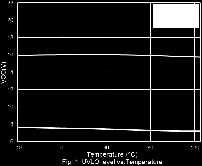

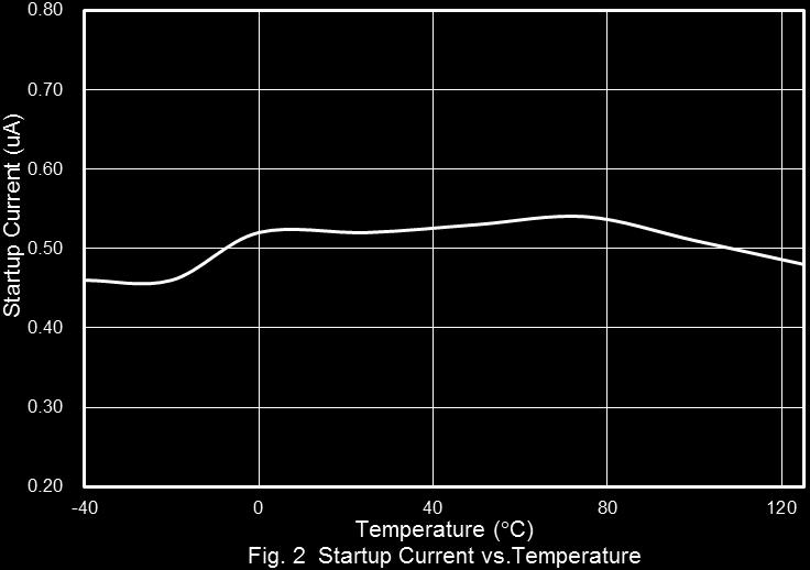

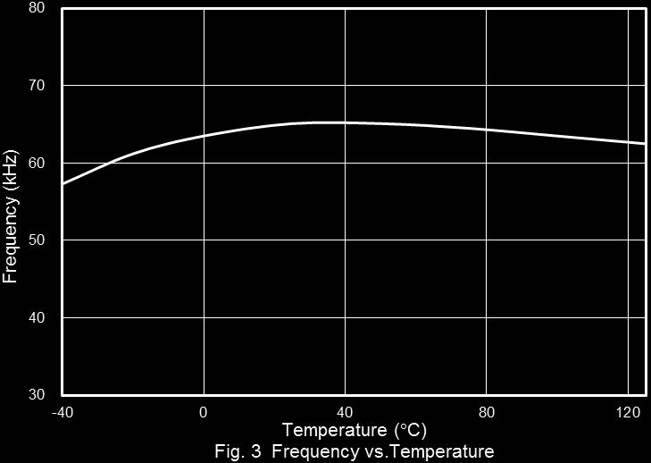
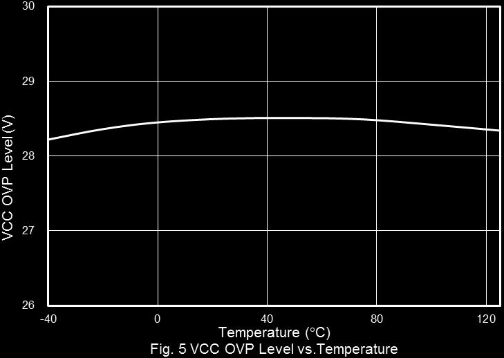

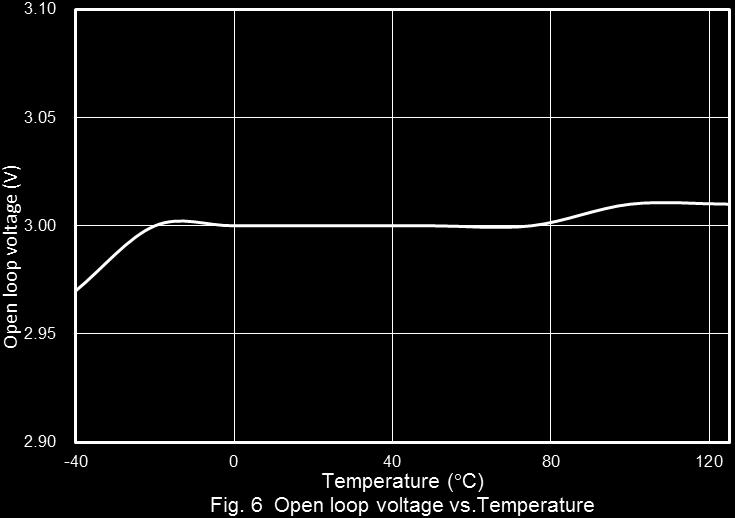
7 Typical Performance Characteristics 7
8 8
9 Application Information Operation Overview The meets the green-power requirement and is intended for the use in those modern switching power suppliers and adaptors which demand higher power efficiency and power-saving. It integrated more functions to reduce the external components counts and the size. Its major features are described as below. Under Voltage Lockout (UVLO) An UVLO comparator is implemented in it to detect the voltage on the VCC pin. It would assure the supply voltage enough to turn on the PWM controller and further to drive the power MOSFET. As shown in Fig. 9, a hysteresis is built in to prevent the shutdown from the voltage dip during startup. Vcc provide supply current. Lower startup current requirement on the PWM controller will help to increase the value of R1 and then reduce the power consumption on R1. By using CMOS process and the special circuit design, the maximum startup current for is only 3 A. If a higher resistance value of the R1 is chosen, it will usually take more time to start up. To carefully select the value of R1 and C1 will optimize the power consumption and startup time. AC input EMI Filter Cbulk R1 D1 C1 UVLO(on) UVLO(off) t VCC CS/OVP GND I(Vcc) operating current (~ ma) Fig. 10 startup current (~ua) Fig. 9 Startup Current and Startup Circuit The typical startup circuit to generate VCC of the is shown in Fig. 10. During the startup transient, the VCC is below UVLO threshold. Before it has sufficient voltage to develop pulse to drive the power MOSFET, R1 will provide the startup current to charge the capacitor C1. Once VCC obtain enough voltage to turn on the and further to deliver the gate drive signal, it will enable the auxiliary winding of the transformer to t Current Sensing and Leading-edge Blanking The typical current mode of PWM controller feedbacks both current signal and voltage signal to close the control loop and achieve regulation. As shown in Fig. 11, the detects the primary MOSFET current from the CS pin, which is not only for the peak current mode control but also for the pulse-by-pulse current limit. The maximum voltage threshold of the current sensing pin is set at 0.85V. From above, the MOSFET peak current can be obtained from below. 0.85V IPEAK (MAX) RS 9
10 optimize EMI performance and lower system cost. The switching frequency substantially centers at 65KHz, and swap between a range of ±3.9KHz. AC Line VCC CS/OVP GND RS LEB time Green-Mode Operation By using the green-mode control, the switching frequency can be reduced under the light load condition. This feature helps to improve the efficiency in light load conditions. The green-mode control is Leadtrend Technology s own property. Fig. 12 shows the characteristics of the switching frequency vs. the comp pin voltage (V COMP) On/Off Control Fig. 11 A leading-edge blanking (LEB) time is included in the input of CS pin to prevent the false-trigger from the current spike. Output Stage and Maximum Duty-Cycle An output stage of a CMOS buffer, with typical 250/-500mA driving capability, is incorporated to drive a power MOSFET directly. And the maximum duty-cycle of is limited to 85% to avoid the transformer saturation. The can be turned off by pulling COMP pin lower than 0.6V. The gate output pin of the will be disabled immediately under such condition. The off-mode can be released when the pull-low signal is removed. Fs 65kHz 23kHz Voltage Feedback Loop V COMP (V) The voltage feedback signal is provided from the TL431 at the secondary side through the photo-coupler to the COMP pin of the. Similar to UC3842, the would carry a diode voltage offset at the stage to feed the voltage divider at the ratio of RA and RB, that is, RB V COMPARATOR RA RB ( PWM ) V COMP A pull-high resistor is embedded internally and can be eliminated externally. Oscillator and Switching Frequency The is implemented with Frequency Swapping function which helps the power supply designers to both Fig. 12 Internal Slope Compensation In the conventional applications, the problem of the stability is a critical issue for current mode controlling, when it operates over 50% duty-cycle. As UC384X, It takes slope compensation from injecting the ramp signal of the RT/CT pin through a coupling capacitor. It therefore requires no extra design for the since it has integrated it already. Adjustable Over Current Compensation In general, the power converter can deliver more current at high input voltage than at low input voltage. To 10
11 compensate this, an offset voltage is added to the CS signal by an internal current source (I OCP) and an external resistor (R OCP) in series between the sense resistor (Rs) and the CS pin, as shown in Fig. 13. By selecting a proper value of the resistor in series with the CS pin, the amount of compensation can be adjusted. The value of I OCP depends on the duty cycle of pin. The equation of I OCP is decreased as: turn off the gate output to stop the switching of power circuit. With the protection mechanism, the average input power will be minimized to remain the component temperature and stress within the safe operating area. VCC (0.625 Duty) 480uA(0.125 Duty 0.625) I OCP 0uA (Duty 0.625) 240uA (Duty 0.125) In light load conditions, the offset should be removed UVLO(on) UVLO(off) COMP OLP UVLO(off) OLP Reset OLP delay time t since it is in same order of magnitude as the current sense signal. Therefore the compensation current is only fully added when the COMP voltage is higher than 1.5V. OLP OLP trip Level t R OCP:470 ~1.2k ; C OCP:47pF~390pF 0.85V OCP Comparator I OCP V BIAS Duty/V COMP Switching Non-Switching Fig. 14 Switching t LEB CS C OCP R OCP R S Over Voltage Protection (OVP) on VCC - Auto Recovery Fig. 13 Over Load Protection (OLP) - Auto Recovery To protect the circuit from damage in over-load condition and short or open-loop condition, the is implemented with smart OLP function. It also features auto recovery function; see Fig. 14 for the waveform. In case of fault condition, the feedback system will force the voltage loop toward the saturation and then pull the The VCC OVP function of the is in auto recovery mode. As soon as the voltage of the VCC pin rises above OVP threshold, the output gate drive circuit will be shutdown simultaneous to turn off the power MOSFET. Fig. 15 shows its operation. voltage high on COMP pin (VCOMP). When the V COMP ramps up to the OLP threshold of 2.6V and continues over OLP delay time, the protection will be activated and then 11
12 OVP Level UVLO (on) UVLO (off) VCC Switching OVP UVLO(off) OVP Reset Non- Switching MOSFET Characteristic Fig. 15 Switching The MOSFET is divided into three operation regions, ohmic region, saturation region, and the cut-off region, shown as Fig. 16. For switching power supply applications, it shall operate in ohmic and cut-off region. Never reach the region of saturation; it would cause damage for acting beyond the maximum safety operating area. It s necessary to check the characteristic of MOSFET. ID VGS5 > VGS4 > VGS3 > VGS2 > VGS1 t t therefore the flat voltage on the CS/OVP pin is proportional to the output voltage. The can sample this flat voltage level after a delay time to perform output over voltage protection. This delay time is used to ignore the voltage ringing from leakage inductance of PWM transformer. The sampling voltage level is compared with internal threshold voltage 0.30V. If the sampling voltage exceeds the OVP trip level, an internal counter starts counting subsequent OVP events. The counter has been added to prevent incorrect OVP detection which might occur during ESD or lightning events. However, when typically 8 cycles of subsequent OVP events are detected, the OVP circuit switches the power MOSFET off. As the protection is auto recovery, the converter restarts after the V CC is lower than UVLO OFF level and then recharge to UVLO ON. Delay Sample OVP Debouce 8 cycle Out 0.30V Fig. 17 CS AUX R OCP R S Ohmic Region Saturation Region VGS5 AUX Winding VGS4 VGS3 Cut-off region VGS2 VGS1 VDS Fig. 16 Output Over Voltage Protection (CS/OVP Pin) - Auto Recovery An output overvoltage protection is implemented in the, as shown in Fig. 17 and 18. It senses the auxiliary voltage via the divided resistors. The auxiliary winding voltage is reflected from secondary winding and Sample Delay CS/OVP Fig
13 OTP Pin --- Auto Recovery The OTP circuit is implemented to sense whether there is any hot-spot of power circuit like power MOSFET or output rectifier. Once an over-temperature condition is detected, the OTP is enabled to shut down the controller to protect the controller. Typically, a NTC is recommended to connect with OTP pin. The NTC resistance will decrease as the device or ambient in high temperature. The relationship is as below. VOTP 100μA R NTC When the V OTP is below the defined voltage threshold (typ. 0.95V), the will shut down the gate output and operate in auto recovery protection mode. As cool down the circuit, NTC resistance will increase and raise V OTP up above 1.05V. Moreover, the restarts. 13
14 Package Information SOT-26 Symbol Dimension in Millimeters Dimensions in Inches Min Max Min Max A B C D F 0.95 TYP TYP H I J M θ Important Notice Leadtrend Technology Corp. reserves the right to make changes or corrections to its products at any time without notice. Customers should verify the datasheets are current and complete before placing order. 14
15 Revision History REV. Date Change Notice 00 Original Specification. 15
LD5536 7/16/2015. Green-Mode PWM Controller with Frequency Swapping. and Integrated Protections. General Description. Features.
 REV: 01 Green-Mode PWM Controller with Frequency Swapping General Description The is built-in with several functions, protection and EMI-improved solution in a tiny package. It takes less components-counts
LD7536R 05/11/2010. Green-Mode PWM Controller with Frequency Swapping and Integrated Protections. General Description. Features.
 05/11/2010 Green-Mode PWM Controller with Frequency Swapping and Integrated Protections Rev. 00 General Description The LD7536R is built-in with several functions, protection and EMI-improved solution
LD9704R 03/15/2017. Green-Mode PWM Controller with Frequency Swapping with protections and MOSFET Integrated. General Description.
 Green-Mode PWM Controller with Frequency Swapping with protections and MOSFET Integrated REV. 00 General Description The is built-in with several functions, protection and EMI-improved solution within
LD /8/2013. Green-Mode PWM Controller with Frequency Swapping and Integrated Protections. General Description. Features.
 10/8/2013 Green-Mode PWM Controller with Frequency Swapping and Integrated Protections Rev. 00 General Description The LD5530 is built-in with several functions, protection and EMI-improved solution in
LD7536E 5/28/2012. Green-Mode PWM Controller with Frequency Swapping and Integrated Protections. General Description. Features.
 5/28/2012 Green-Mode PWM Controller with Frequency Swapping and Integrated Protections Rev. 00 General Description The is built-in with several functions, protection and EMI-improved solution in a tiny
LD /15/2011. Green-Mode PWM Controller with Frequency Swapping and Integrated Protections. Features. General Description.
 12/15/2011 Green-Mode PWM Controller with Frequency Swapping and Integrated Protections Rev. 02a General Description The LD7536 is built-in with several functions, protection and EMI-improved solution
LD7523 6/16/2009. Smart Green-Mode PWM Controller with Multiple Protections. General Description. Features. Applications. Typical Application REV: 00
 6/16/2009 Smart Green-Mode PWM Controller with Multiple Protections REV: 00 General Description The LD7523 is a low startup current, current mode PWM controller with green-mode power-saving operation.
LD7552B 1/2/2008. Green-Mode PWM Controller with Integrated Protections. General Description. Features. Applications. Typical Application. Rev.
 Rev. 01a LD7552B 1/2/2008 Green-Mode PWM Controller with Integrated Protections General Description The LD7552B are low cost, low startup current, current mode PWM controllers with green-mode power- saving
VCC. UVLO internal bias & Vref. Vref OK. PWM Comparator. + + Ramp from Oscillator GND
 Block Diagram VCC 40V 16.0V/ 11.4V UVLO internal bias & Vref RT OSC EN Vref OK EN OUT Green-Mode Oscillator S COMP 2R R Q R PWM Comparator CS Leading Edge Blanking + + Ramp from Oscillator GND Absolute
LD7550-B. Green-Mode PWM Controller. General Description. Features. Applications. Typical Application 01/03/2005 LD7550-B
 01/03/2005 Green-Mode PWM Controller General Description The LD7550-B is a low cost, low startup current, current mode PWM controller with green-mode power-saving operation. The integrated functions such
LD7552. Green-Mode PWM Controller. Features. General Description. Applications. Typical Application 2/21/2005
 2/21/2005 Green-Mode PWM Controller General Description The LD7552 is a low cost, low startup current, current mode PWM controller with green-mode power-saving operation. The integrated functions such
LD /14/2013. Green-Mode PWM Controller with HV Start-Up Circuit and Soft Start time Adjustment. Features. General Description.
 06/14/2013 Green-Mode PWM Controller with HV Start-Up Circuit and Soft Start time Adjustment REV. 01 General Description The brings high performance, highly integrated functions, protections and EMI-improve
LD7752B 6/11/2013. Green-Mode PWM Controller with HV Start-Up Circuit and Soft Start time Adjustment. Features. General Description.
 6/11/2013 Green-Mode PWM Controller with HV Start-Up Circuit and Soft Start time Adjustment REV. 00 General Description The brings high performance, highly integrated functions, protections and EMI-improve
LD7577 1/15/2009. High Voltage Green-Mode PWM Controller with Brown-Out Protection. General Description. Features. Applications. Typical Application
 Rev. 01 General Description High Voltage Green-Mode PWM Controller with Brown-Out Protection The LD7577 integrates several functions of protections, and EMI-improved solution in SOP-8 package. It minimizes
LD7531 6/25/2008. Green-Mode PWM Controller with Frequency Trembling and Integrated Protections. Features. General Description.
 REV: 00 LD7531 6/25/2008 Green-Mode PWM Controller with Frequency Trembling and Integrated Protections General Description The LD7531 is built-in with several functions, protection and EMI-improved solution
LD5538R 08/01/2016. Green-Mode PWM Controller with Frequency Swapping and Integrated Protections. Features. General Description.
 REV. 00 GreenMode PWM Controller with Frequency Swapping and Integrated Protections General Description The is builtin with several functions, protection and EMIimproved solution in a tiny package. It
LD /29/2016. Green-Mode PWM Controller with Frequency Swapping and Integrated Protections. Features. General Description.
 GreenMode PWM Controller with Frequency Swapping and Integrated Protections REV. 01 General Description The is builtin with several functions, protection and EMIimproved solution in a tiny package. It
LD7750 2/23/2010. High Voltage Green-Mode PWM Controller with Over Temperature Protection. Features. Applications. Typical Application
 Rev. 00b General Description High Voltage Green-Mode PWM Controller with Over Temperature Protection Features LD7750 2/23/2010 The LD7750 integrates several functions of protections, and EMI-improved solution
Preliminary GR1230R. Multi-Mode PWM Controller with Integrated Protections. Features. Description. Applications. Typical Application Information
 Multi-Mode PWM Controller with Integrated Protections Features Low Start-Up Current (
LD /01/2013. Boost Controller for LED Backlight. General Description. Features. Applications. Typical Application REV: 00
 04/01/2013 Boost Controller for LED Backlight REV: 00 General Description The LD5861 is a wide-input asynchronous current mode boost controller, capable to operate in the range between 9V and 28V and to
LD7575 6/16/2008. Green-Mode PWM Controller with High-Voltage Start-Up Circuit. General Description. Features. Applications. Typical Application
 Green-Mode PWM Controller with High-Voltage Start-Up Circuit LD7575 6/16/2008 REV: 04b General Description The LD7575 is a current-mode PWM controller with excellent power-saving operation. It features
LD7830 VSEN GND ISEN COMP
 8/17/2012 High Power Factor Flyback LED Controller with HV Start-up REV: 01a General Description The LD7830 is a HV start-up Flyback PFC controller, specially designed for LED lighting appliances. It operates
Green-Mode PWM Controller with Hiccup Protection
 Green-Mode PWM Controller with Hiccup Protection Features Current Mode Control Standby Power below 100mW Under-Voltage Lockout (UVLO) Non-Audible-Noise Green-Mode Control 65KHz Switching Frequency Internal
Green-Mode PWM Controller with Hiccup Protection
 Green-Mode PWM Controller with Hiccup Protection Features Current mode control Standby power below 100mW Under-voltage lockout (UVLO) Non-audible-noise green-mode control 100KHz switching frequency Internal
Green-Mode PWM Controller with Hiccup Protection
 Green-Mode PWM Controller with Hiccup Protection Features Current Mode Control Standby Power below 100mW Under-Voltage Lockout (UVLO) Non-Audible-Noise Green-Mode Control 65KHz Switching Frequency Internal
LD5857 4/15/2014. Boost Controller for LED Backlight. General Description. Features. Applications. Typical Application REV: 00
 4/15/2014 Boost Controller for LED Backlight REV: 00 General Description The LD5857 is a wide-input asynchronous current mode boost controller, capable to operate in the range between 9V and 28V and to
Green-Mode PWM Controller with Integrated Protections
 Green-Mode PWM Controller with Integrated Protections Features Current mode control Very low startup current Under-voltage lockout (UVLO) Non-audible-noise green-mode control Programmable switching frequency
Green-Mode PWM Controller with Integrated Protections
 Green-Mode PWM Controller with Integrated Protections Features Current mode PWM Very low startup current Under-voltage lockout (UVLO) Non-audible-noise green-mode control Programmable switching frequency
Green mode PWM Flyback Controller with External Over Temperature Protection
 Green mode PWM Flyback Controller with External Over Temperature Protection General Description is a high performance, low startup current, low cost, current mode PWM controller with green mode power saving.
Preliminary GR8875N Series
 Green-Mode PWM Controller with High Voltage Startup Circuit Features High-Voltage (700V) Startup Circuit Very Low Startup Current (
Preliminary GL8211/11B
 High Power Factor & Accuracy Constant Current LED Driver Features High Power Factor by One Cycle Control Accuracy Constant Current Low BOM Cost Linear Dimming on DIM Pin Average Current / Fixed Frequency
LD7838GR. High Power Factor Flyback LED Controller. with HV Start-up. Features. General Description. Applications. Typical Application 11/22/2016
 High Power Factor Flyback LED Controller with HV Start-up REV. 01 General Description The is a 700V HV start-up active PFC Flyback controller, specially designed for LED lighting application. This device
LD5718AC 09/22/2016. Primary-Side Quasi-Resonant Controller, Operating in CV/CC Mode. Features. General Description. Applications. Typical Application
 REV. 00 General Description Primary-Side Quasi-Resonant Controller, The is a primary-side Quasi-Resonant controller capable of operating in CV/CC mode for small to medium power AC/DC charger and adapter.
TS19702 High Power Factor Corrector LED Driver
 SOT-26 Pin Definition: 1. VCC 2. Ground 3. Output 4. Dimming 5. Compensation 6. Current Sense Description The TS19702 is a highly-integrated, low startup current, average current mode, one cycle control
LD7576/76H/76J/76K 12/9/2009
 12/9/2009 Green-Mode PWM Controller with High-Voltage Start-Up Circuit and Adjustable OLP Delay Time REV. 04a General Description The LD7576X series brings high performance, and combines highly integrated
EM8631S. Green mode PWM Flyback Controller. Features. General Description. Ordering Information. Applications. Typical Application Circuit
 Green mode PWM Flyback Controller General Description is a high performance, low startup current, low cost, current mode PWM controller with green mode power saving. The integrates functions of Soft Start(SS),
LD7513A 11/15/2013. Primary Side Quasi-Resonant BJT Controller with CV/CC Operation. Features. General Description. Applications. Typical Application
 Primary ide Quasi-esonant BJT Controller with CV/CC Operation LD7513A 11/15/2013 ev. 00 General Description The LD7513A is an excellent primary side feedback BJT controller with CV/CC operation, integrated
Preliminary GR9210RL. Multi-Mode PWM Power Switch with Primary-Side Feedback. Features. Description. Applications. Typical Application Information
 Multi-Mode PWM Power Switch with Primary-Side Feedback Features Built-in 650V Power MOSFET Low Start-Up Current (
CR6853. Novel Low Cost Green-Power PWM Controller With Low EMI Technique
 Novel Low Cost Green-Power PWM Controller With Low EMI Technique Feature Low Cost, PWM&PFM&CRM (Cycle Reset Mode) Low Start-up Current (about 1.5µA) Low Operating Current (about 1.4mA) Current Mode Operation
LD7591 3/4/2010. Transition-Mode PFC Controller with Fault Condition Protection. Features. General Description. Applications
 3/4/2010 Transition-Mode PFC Controller with Fault Condition Protection REV. 00 General Description The LD7591 is a voltage mode PFC controller operating on transition mode, with several integrated functions
LD /28/2015. LED Lighting Output Current Ripple Suppressor. General Description. Features. Applications. Typical Application REV.
 LED Lighting Output Current Ripple Suppressor REV. 00 General Description The is an output current ripple suppressor for LED lighting. It supports easy use at output terminal with isolation or non-isolation
Flexible Dimming Solution by PWM / 0-10V / Potentiometer. Features 5V_PWM LED+ 0 10V RDIM DDIM CDIM RISET. RPhoto Min.
 Flexible Dimming Solution by PWM / 0-10V / Potentiometer REV. 00 General Description The contains a processor which can convert the three different inputs of dimmer type include 0~10V DC potential, 0~100%
Green-Mode PWM Controller with Integrated Protections
 Green-Mode PWM Controller with Integrated Protections Features High-voltage (500) startup circuit Current mode PWM ery low startup current (
Not Recommended. TS19702 High Power Factor Corrector LED Driver. Description. Features. Application. Ordering Information
 SOT-26 Pin Definition: 1. VCC 2. Ground 3. Output 4. Dimming 5. Compensation 6. Current Sense Description The TS19702 is a highly-integrated, low startup current, average current mode, one cycle control
CR6842. Green-Power PWM Controller with Freq. Jittering. Features. Applications. General Description. Leading-edge blanking on Sense input
 Green-Power PWM Controller with Freq. Jittering Features Low Cost, Green-Power Burst-Mode PWM Very Low Start-up Current ( about 7.5µA) Low Operating Current ( about 3.0mA) Current Mode Operation Under
High Voltage 4-Channel LED Controller Driver. Features. 33uF NMOS R1 OVP PWM DIM LOSC STATUS. FB4 Gate4. Sense4 FB3 Gate3 Sense3
 High Voltage 4-Channel LED Controller Driver LD7890 11/5/2013 REV: 01 General Description The LD7890 is a 4-channel LED controller with a boost switching controller. It s an ideal solution for driving
Green-Mode PWM Controller with Integrated Protections
 Green-Mode PWM Controller with Integrated Protections Features High-voltage (500) startup circuit Current mode PWM ery low startup current (
LD9010A 12/08/2016. Green Mode Power Switch for Non-isolation Power Converter. General Description. Features. Typical Application REV.
 Green Mode Power witch for Non-isolation Power Converter REV. 00 General escription The is a green mode PFM driver integrated with 700V MOFET in a OP package. It is capable to operate at a maximum frequency
FAN6747WALMY Highly Integrated Green-Mode PWM Controller
 FAN6747WALMY Highly Integrated Green-Mode PWM Controller Features High-Voltage Startup AC-Line Brownout Protection by HV Pin Constant Output Power Limit by HV Pin (Full AC-Line Range) Built-in 8ms Soft-Start
High Power Factor & Accuracy Constant Current LED Driver
 High Power Factor & Accuracy Constant Current LED Driver Features Built-in 600V Power MOSFET TM (Transition Mode) Fixed On -Time PFC Control Accuracy Constant Current Low BOM Cost Inductor Size Reduction
VERSATILE COST EFFECTIVE GREEN PWM CONTROLLER General Description. Features
 General Description The is a low startup current, current mode PWM controller with green-mode power-saving operation. The PWM switching frequency at normal operation is externally programmable and is trimmed
DP9126IX. Non-Isolated Buck APFC Offline LED Power Switch FEATURES GENERAL DESCRIPTION APPLICATIONS TYPICAL APPLICATION CIRCUIT
 Non-Isolated Buck APFC Offline LED Power Switch DP9126IX FEATURES Active PFC for High PF and Low THD PF>0.9 with Universal Input Built-in HV Startup and IC Power Supply Circuit Internal 650V Power MOSFET
LD /03/2017. Constant Voltage and Constant Current Controller. Features. General Description. Applications. Typical Application REV.
 Constant Voltage and Constant Current Controller REV. 00 General Description The is built-in with a high-accuracy 1.212V reference voltage, two op-amps and a low-side current sensing circuit in a SOT-26
FAN6862R / FAN6862L Highly Integrated Green-Mode PWM Controller
 FAN6862R / FAN6862L Highly Integrated Green-Mode PWM Controller Features Low Startup Current: 8µA Low Operating Current in Green Mode: 3mA Peak-Current-Mode Operation with Cycle-by-Cycle Current Limiting
Novel Low Cost Green-Power PWM Controller
 2263 Novel Low Cost Green-Power PWM Controller Features Low Cost, PWM&PFM&CRM (Cycle Reset Mode) Low Start-up Current (about 8µA) Low Operating Current (about 2mA) Current Mode Operation Under Voltage
G1102 High Precision CC/CV Primary-Side PWM Controller
 ANALOG PWM IC 1. General Description G1102 is a high performance offline PWM controller for low power AC/DC charger and adaptor applications. It operates in primary-side regulation. Consequently, opto-coupler
Current Mode PWM Power Switch GR8935L XXXXX
 Current Mode PWM Power Switch Preliminary GR8935L Features Current mode PWM ery low startup current Under-voltage lockout ULO Non-audible-noise green-mode control Fixed switching frequency of 50KHz Cycle-by-cycle
DP9122 Non-isolated Quasi-Resonant Buck LED Power Switch
 FEATURES GENERAL DESCRIPTION Integrated with 500V MOSFET No Auxiliary Winding Needed Quasi-Resonant for High Efficiency Built-in Thermal Foldback Built-in Charging Circuit for Fast Start-Up ±4% CC Regulation
UNISONIC TECHNOLOGIES CO., LTD UC1103 Preliminary CMOS IC
 UNISONIC TECHNOLOGIES CO., LTD HIGH PRECISION CC/CV PRIMARY SIDE SWITCHING REGULATOR DESCRIPTION The UTC UC1103 is a primary control unit for switch mode charger and adapter applications. The controlled
Current Mode PWM Power Switch. Code A B G H I J Year Code A B C Month Jan. Feb. Mar. Apr.
 Current Mode PWM Power Switch Preliminary GR8935 Features Current mode PWM ery low startup current Under-voltage lockout ULO Non-audible-noise green-mode control Fixed switching frequency of 50KHz Cycle-by-cycle
EUP A,30V,1.2MHz Step-Down Converter DESCRIPTION FEATURES APPLICATIONS. Typical Application Circuit
 1.2A,30V,1.2MHz Step-Down Converter DESCRIPTION The is current mode, step-down switching regulator capable of driving 1.2A continuous load with excellent line and load regulation. The can operate with
LD7889A 3/29/ Channel LED Backlight Driver. General Description. Features. Applications. Typical Application REV: 00
 3/29/2012 4-Channel LED Backlight Driver REV: 00 General Description The LD7889A is a 4-channel linear current controller which combines with a boost switching controller. It s an ideal solution for driving
Quasi-Resonant Flyback PWM Controller
 Quasi-Resonant Flyback PWM Controller Features QR ZVS at switch turn-on PFM mode at light load condition Controllable built-in PFC power supply 130 KHz maximum frequency limit Internal minimum off-time
UNISONIC TECHNOLOGIES CO., LTD UPSR104 Preliminary CMOS IC
 UNISONIC TECHNOLOGIES CO., LTD HIGH PRECISION CC/CV PRIMARY-SIDE PWM CONTROLLER DESCRIPTION The UTC UPSR104 is a primary controller mode charger and adapter applications. The controlled variable is transferred
FAN6751MR Highly-Integrated Green-Mode PWM Controller
 FAN6751MR Highly-Integrated Green-Mode PWM Controller Features High-Voltage Startup Low Operating Current: 4mA Linearly Decreasing PWM Frequency to 18KHz Fixed PWM Frequency: 65KHz Peak-current-mode Control
LD /07/ Channel LED Backlight Driver. General Description. Features. Applications. Typical Application REV: 05
 10/07/2011 4 Channel LED Backlight Driver REV: 05 General Description The LD7889 is a 4-channel linear current controller which combines with a boost switching controller. It s an ideal solution for driving
WS3252 Product Description
 High Precision CC/CV Primary-Side PWM Controller Features 5uA ultra-low startup current 2mA Low operating current ±5% Constant Voltage Regulation at Universal AC input Primary-side Sensing and Regulation
SMD7325 PWM Cntroller IC for Flyback Power Supply
 FEATUES Excellent Gate Driving Capability for High Efficiency Performance 1uA Low Startup Current 0.8mA Low Operating Current Low Power Consumption at Burst Mode Multiple Protection Functions (OTP, OVP,
SG6860 Low-Cost, Green-Mode PWM Controller for Flyback Converters
 SG6860 Low-Cost, Green-Mode PWM Controller for Flyback Converters Features Green-Mode PWM Supports the Blue Angel Eco Standard Low Startup Current: 9µA Low Operating Current: 3mA Leading-Edge Blanking
SP6853 Green-Mode PWM Controller
 DESCRIPTION The SP6853 is a low cost, low startup current, current mode PWM controller with green-mode power-saving operation. The integrated functions include the leading-edge blanking of the current
Constant Voltage and Constant Current Controller. Features
 09/06/2011 Constant Voltage and Constant Current Controller Rev. P1 General Description Features The is built-in with a high-accuracy 1.2V voltage reference, two op-amps and a low-side current sensing
TS19701A CC/CV Primary-Side PWM Controller
 SOT-26 Pin Definition: 1. GND 2. Gate 3. Current Sense 4. INV 5. Compensation 6. VDD Description TS19701A is a high performance offline PWM Power switch for low power AC/DC charger and adapter applications.
Single-Stage PFC Buck Current Control LED Driver
 Single-Stage PFC Buck Current Control LED Driver DESCRIPTION The TS19720 is a high power factor and high accuracy constant current PWM controller. It is able to control total harmonic distortion (THD)
AP3103A. Description. Pin Assignments. Features. Applications. A Product Line of. Diodes Incorporated COST EFFECTIVE GREEN PWM CONTROLLER AP3103A
 COST EFFECTIVE GREEN PWM CONTROLLER Description Pin Assignments The is a low startup current, current mode PWM controller with green-mode power-saving operation. The PWM switching frequency at normal operation
UNISONIC TECHNOLOGIES CO., LTD UCSR3651S Preliminary CMOS IC
 UNISONIC TECHNOLOGIES CO., LTD UCSR3651S Preliminary CMOS IC HIGH PRECISION CC/CV PRIMARY-SIDE PWM POWER SWITCH DESCRIPTION The UTC UCSR3651S is a primary control switch mode charger and adapter applications.
FAN6747 Highly Integrated Green-Mode PWM Controller
 FAN6747 Highly Integrated Green-Mode PWM Controller Features High-Voltage JFET Startup AC-Line Brownout Protection by HV Pin Constant Output Power Limit by HV Pin (Full AC-Line Range) Two-Level Over-Current
EUP A,30V,500KHz Step-Down Converter DESCRIPTION FEATURES APPLICATIONS. Typical Application Circuit
 5A,30V,500KHz Step-Down Converter DESCRIPTION The is current mode, step-down switching regulator capable of driving 5A continuous load with excellent line and load regulation. The operates with an input
TS19730 Single-Stage Low THD Buck-Boost PWM Control LED Driver
 SOT-26 Pin Definition: 1. V CC 2. GND 3. OUT 4. CL 5. COM 6. CS Description The is a high power factor, low THD and high accuracy constant current PWM controller. achieves high power factor and high efficiency
Primary-Side Regulation PWM Controller for PFC LED Driver
 Preliminary R7304 Primary-Side Regulation PWM Controller for PFC LED Driver General Description RT7304 is an active power factor controller specifically designed for use as a constant current LED driver.
HT7L4811 Non-isolation Buck LED Lighting Driver with Active PFC
 Non-isolation Buck LED Lighting Driver with Active PFC Features Tiny package SOT23-6 Non-isolation buck topology Low BOM Cost Wide AC input range from 85VAC to 265VAC High Power Factor of >0.9 without
G1513 High Performance Current Mode PWM Controller
 ANALOG PWM IC 1. General Description The G1513 is a high performance AC/DC power supply controller for battery charger and adapter applications requirements up to 40W It can meet less than 80 mw standby
GREEN MODE PWM CONTROLLER General Description. Features. Applications
 查询 供应商 捷多邦, 专业 PCB 打样工厂,24 小时加急出货 General Description The is a green PWM controller operating in current mode. It is specially designed for off-line AC- DC adapter and battery charger applications where
2A, 23V, 380KHz Step-Down Converter
 2A, 23V, 380KHz Step-Down Converter General Description The is a buck regulator with a built-in internal power MOSFET. It achieves 2A continuous output current over a wide input supply range with excellent
FAN6754 Highly Integrated Green- Mode PWM Controller Brownout and V Limit Adjustment by HV Pin
 FAN6754 Highly Integrated Green- Mode PWM Controller Brownout and V Limit Adjustment by HV Pin Features High-Voltage Startup AC Input Brownout Protection with Hysteresis Monitor HV to Adjust V Limit Low
FL103 Primary-Side-Regulation PWM Controller for LED Illumination
 FL103 Primary-Side-Regulation PWM Controller for LED Illumination Features Low Standby Power: < 30mW High-Voltage Startup Few External Component Counts Constant-Voltage (CV) and Constant-Current (CC) Control
Single-Stage Buck Current Control LED Driver with High Voltage MOSFET Integrated
 Single-Stage Buck Current Control LED Driver with High Voltage MOSFET Integrated DESCRIPTION The TS19751 is a high performance LED driver which accuracy constant current PWM controller with high voltage
AP8022. AiT Semiconductor Inc. APPLICATION ORDERING INFORMATION TYPICAL APPLICATION
 DESCRIPTION The consists of a Pulse Width Modulator (PWM) controller and a power MOSFET, specifically designed for a high performance off-line converter with minimal external components. offers complete
DP9127. Non-isolated Quasi-Resonant Buck LED Power Switch GENERAL DESCRIPTION FEATURES APPLICATIONS TYPICAL APPLICATION CIRCUIT
 1 FEATURES Integrated with 500V MOSFET No Auxiliary Winding Needed Quasi-Resonant for High Efficiency Built-in Thermal Foldback Built-in Charging Circuit for Fast Start-Up ±4% CC Regulation Very Low VDD
WS3254 Product Description
 High Precision Primary-Side Off-line PWM Power Switch Features 5uA ultra-low startup current 2mA Low operating current ±5% Constant Voltage Regulation at Universal AC input Primary-side Sensing and Regulation
WS3256 Product Description
 High Precision Primary-Side Off-line PWM Power Switch Features 5uA ultra-low startup current 2mA Low operating current ±5% Constant Voltage Regulation at Universal AC input Primary-side Sensing and Regulation
MP6902 Fast Turn-off Intelligent Controller
 MP6902 Fast Turn-off Intelligent Controller The Future of Analog IC Technology DESCRIPTION The MP6902 is a Low-Drop Diode Emulator IC for Flyback converters which combined with an external switch replaces
R7731. Burst Triple Mode PWM Flyback Controller. Features. General Description. Applications. Typical Application Circuit
 Burst Triple Mode PWM Flyback Controller General Description The R7731 is a high performance, low cost, low start-up current, current mode PWM controller with burst triple mode to support green mode power
FL7701 Smart LED Lamp Driver IC with PFC Function
 Click here for this datasheet translated into Chinese! FL7701 Smart LED Lamp Driver IC with PFC Function Features Digitally Implemented Active PFC Function (No Additional Circuit Necessary for High PF)
AP3105/V/L/R. Pin Assignments. Description. Applications. Features. A Product Line of. Diodes Incorporated COST EFFECTIVE GREEN PWM CONTROLLER
 COST EFFECTIVE GREEN PWM CONTROLLER Description Pin Assignments The is a low startup current, current mode PWM (Top View) controller with green-mode power-saving operation. The PWM switching frequency
EUP3410/ A,16V,380KHz Step-Down Converter DESCRIPTION FEATURES APPLICATIONS. Typical Application Circuit
 2A,16V,380KHz Step-Down Converter DESCRIPTION The is a current mode, step-down switching regulator capable of driving 2A continuous load with excellent line and load regulation. The can operate with an
DESCRIPTION FEATURES PROTECTION FEATURES APPLICATIONS. RS2320 High Accurate Non-Isolated Buck LED Driver
 High Accurate Non-Isolated Buck LED Driver DESCRIPTION RS2320 is especially designed for non-isolated LED driver. The building in perfect current compensation function ensures the accurate output current.
For buy, please contact: FEATURES C3 R3 MT MT7990 VDD DRAIN
 DESCRIPTION The is a single-stage, primary side control AC-DC LED driver with active power factor correction. The integrates on-chip PFC circuit operates in discontinuous conduction mode (DCM) to achieve
FL7732 Single-Stage PFC Primary-Side-Regulation Offline LED Driver
 FL7732 Single-Stage PFC Primary-Side-Regulation Offline LED Driver Features Cost-Effective Solution: No Input Bulk Capacitor or Feedback Circuitry Power Factor Correction Accurate Constant-Current (CC)
Single-Stage PFC Buck Current Control LED Driver With High Voltage MOSFET Integrated
 Single-Stage PFC Buck Current Control LED Driver With High Voltage MOSFET Integrated DESCRIPTION TS19721A a very efficient constant current controller for driving LED lamps in non-dimmable lighting applications.
DESCRIPTION FEATURES APPLICATIONS TYPICAL APPLICATION
 MP5016 2.7V 22V, 1A 5A Current Limit Switch with Over Voltage Clamp and Reverse Block The Future of Analog IC Technology DESCRIPTION The MP5016 is a protection device designed to protect circuitry on the