Preliminary report : DRM+ measurements in band II
|
|
|
- May Tucker
- 6 years ago
- Views:
Transcription


1 Preliminary report : DRM+ measurements in band II Author: Dipl.-Ing. Friederike Maier Institute of Communications Technology University of Hanover Germany March 29, 2010
2 Contents 1 Contents 1 Introduction 2 2 DRM+ System parameter Encoding Interleaving Mobile reception System setup Equipment Transmission content Measurement parameters Measurements Measuring locations Measurements in urban environments Measurements behind the railway station Measurements in the "Suedstadt" Measurement of the coverage limit Measurements with 4-QAM Measurements with 16-QAM Conclusion 15 A The transmit antenna 15
3 2 DRM+ System parameter 2 1 Introduction DRM+ is an enhancement of the existing DRM (Digital Radio Mondial) standard up to band III. It has been approved in the ETSI DRM standard [1] in To analyse system performance, a eld trial was carried out within the scope of the pilot project "Digital radio broadcast for local area with the system DRM", which is carried out between the Niedersächsische Landesmedienanstalt (NLM) and the Institute of Communications Technology of the University of Hanover. The measurements were made in the city of Hanover, Germany and its sourroundings in winter/spring 2009/10. This report contains a description of the DRM+ system parameters, the system setup and equipment that was used in the trial and the measuring results that were optained in the measuring campaign. 2 DRM+ System parameter The DRM+ system parameter are shown in the following table: System parameter Modulation OFDM Data rate kbps Subcarrier modulation 4-/16-QAM Signalbandwith 96 khz Subcarrierspread Hz Number of subcarriers 213 Symbol duration 2.25 ms Guard interval duration 0.25 ms Frame length 100 ms Number of programs Encoding In DRM Mode E with 4-QAM the MSC (Main Service Channel), which contains the user data, has the following protection levels with the corresponding code rates and bit rates: MSC: 4-QAM Protection level Code rate Bit rate [kbit/s] In DRM Mode E with 16-QAM the MSC uses multilevel coding and has the following protection levels with the corresponding overall code rates and bit rates: MSC: 16-QAM Protection level Code rate Bit rate [kbit/s]
4 3 System setup 3 The SDC (Service Description Channel), which contains signaling data, is modulated with 4-QAM uses the following code rates: SDC: 16-QAM Code Rate The FAC (Fast Access Channel) uses a x code rate of R = Interleaving In order to improve the robustness of the bitstream to channel errors, bit interleaving is carried out over one frame (100 ms) and convolutional cell interleaving over 6 frames (600 ms). 2.3 Mobile reception DRM+ has a subcarrier spacing of Hz. A rule of thump is that a dopller spread of 10 % of the subcarrier spacing is ok. At carrier frequencies around f 0 = 100 MHz this makes a receiver velocity of v = 3.6 = km/h. Where c = m/s is the speed of light Hz c f 0 The cell interleaver over 600 ms only works properly for receiver velocities v 10 km/h. Therefore in frequency at fading channels with slow receiver velocities transmitter delay diversity could enhance system performance. This will be evaluated in Hanover in further measurements. 3 System setup The transmitter was located at the University of Hanover, the transmitting antenna was mounted on the roof of the University building (Appelstr.9A, Hannover, GPS: lat: , long: 9.712) at a high of 70 m above ground. Transmitting power is licenced up to 30 W ERP at a frequency of 95.2 MHz. Tests were made with one very roboust 4-QAM modulation and one 16-QAM modulation with hight data rates. The details can be found in the following tables: MSC: 4-QAM Protection level Code rate Bit rate [kbit/s] MSC: 16-QAM Protection level Code rate Bit rate [kbit/s] For SDC the more robust mode was choosen: SDC: 16-QAM Code Rate 0.25 For this encodings simulation results of the required SNR values are available in the DRM ETSI standard [1] in Annex A.

5 3 System setup Equipment Figure 1: Transmitting antenna for vertical polarised transmission The following equipment was used for the measurements: Fraunhofer Contentserver RFmondial Modulator Nautel Exciter/Amplier NVE Transmit antenna: Kathrein K , 4- Element Yagi directional antenna (direction: 120 ), measurements were conducted with horizontal (antenna array) and vertical polarisation (see details in annex A), gure 1 shows the vertically mounted antenna Receive antenna: Kathrein K / BN , Monopole, an antennafactor of = 10 db was measured, the antenna was mounted on the roof of a van at a hight of around 2 m HF-Frontend: Rhode & Schwarz ESVB Measuring receiver, 10.7 MHz IF Field strength measurements: ESVB, BW: 300 khz A/D converter Perseus RFmondial Software Receiver 3.2 Transmission content The transmission consisted in both modes in an AAC encoded stereo audio stream and a synchronous pseudo random bit sequence (prbs) which was used for the calculation of the bit error rate (BER) (see [2] for details). 3.3 Measurement parameters The following parameters were recorded and analysed during the measurements: Field strength (measured with Rhode & Schwarz ESVB Measuring receiver, BW: 300 khz, RMS) triggered via GPIB every 16th frame (1.6 sec) GPS coordinates Bit error rate
![4 Measurements 5 Signal to noise ratio (calculated via the time correlation/syncronisation, see [3]) Receiver status information (status of audio decoding, shows if one or more audio frames are](/docs-images/78/77978748/images/6-0.jpg "corrupted within one DRM multiplex frame, see [2]) 4 Measurements 4.")
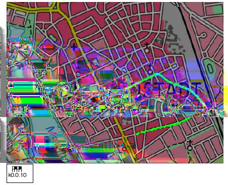
6 4 Measurements 5 Signal to noise ratio (calculated via the time correlation/syncronisation, see [3]) Receiver status information (status of audio decoding, shows if one or more audio frames are corrupted within one DRM multiplex frame, see [2]) 4 Measurements 4.1 Measuring locations Measurements were conducted at two places in the city of Hanover and on one radial route in the direction of the main beam as shown in gure 2. Figure 2: Measuring locations and routes (mapsource: Bundesamt für Kartographie und Geodäsie) 4.2 Measurements in urban environments The rst measurements were conducted with horizontal antenna polarization. As the receiving antenna is vertically mounted on the roof of a car, the antenna was rotated to vertical polarization and the measurement results were compared. The dierent antenna patterns has to be taken into account, but as the location behind the railway station lies in the main beam and the location in the Suedstadt at an angle of around 12 there should be no big dierence. The measurements of the horizontal polarized transmission were conducted the There was some snow and a lot of ice on the ground. The vertically polarized measurements were conducted the There was sometimes sun, mostly overcast and little snow on the ground.


 Horizontal polarization (b) Vertical polarization Figure 4: Field strength in an \"dense\" urban environment (mapsource: Bundesamt für Kartographie und Geodäsie)")

7 4 Measurements Measurements behind the railway station In the streets behind the main station of Hanover a kind of dense urban environment with high buildings and small streets can be found (see gure 3). The average distance to the transmitter is around 2.5 km. Measurements were made in 16-QAM Mode (Coderate 0.5). Figure 3: Pictures of the environment behind the railway station Figure 4 shows the eld strength distribution for the horizontal an vertical polarized transmission. For horizontal transmission the variability of the eldstrength is between 30 and above 50 dbµv/m, for vertical transmission it is mostly above 40 dbµv/m. (a) Horizontal polarization (b) Vertical polarization Figure 4: Field strength in an "dense" urban environment (mapsource: Bundesamt für Kartographie und Geodäsie) Figure 5 shows a plot of the receiver status information (rsta) which describes whether all audio frames are ok (green) or one or more audioframes are corrupted (red). As there is enough ldstrength, reception was mostly without errors with both polarizations. In gure 6 a comparision of the eld strength, the SNR, the BER and the RSTA (0: all audioframes ok, 1 one or more audio frames corrupted) for the horizontal polarized transmission is plotted over the frames (one frame corresponds to 100 ms). Figure 7 shows the same for the vertical polarized
 transmission.")

8 4 Measurements 7 (a) Horizontal polarization (b) Vertical polarization Figure 5: Measurement of the audio data in the urban environment (mapsource: Bundesamt für Kartographie und Geodäsie) transmission. Figure 6: Measurement results in a "dense" urban environment with horizontally polarized transmission Here the eld strength dierence is more obvious. In horizontal transmission the eldstrength is mostly around 50 dbµv/m, for vertical transmission it is up to 70 dbµv/m. With horizontal polarization the bit error rate is higher at some places and there are some corrupted audio frames whereas with vertical polarization there are almost no errors. The calculated SNR is variating much
9 4 Measurements 8 Figure 7: Measurement results in a "dense" urban environment with vertically polarized transmission more in horizontal polarization, the maximum value of around 28 db is caused by calculation Measurements in the "Suedstadt" Further measurements were conducted in the Suedstadt of Hanover, an urban residential district with most buildings with around 5-6 oors. The average distance to the transmitter here is 4 km. Figure 8 shows the eld strength distribution for the horizontal an vertical polarized transmission. For horizontal transmission the variability of the eldstrength is between 30 and 50 dbµv/m, for vertical transmission it is mostly above 40 dbµv/m. Figure 9 shows a plot of the receiver status information (rsta). Here a dierence for vertical and horizontal polarization can be seen. As also shown in gure 10 and 11 with eldstrengthes above 46 dbµv/m reception is possible without errors in the urban environment. The corresponding calculated SNR is around 18 db.
 Vertical polarization")


10 4 Measurements 9 (a) Horizontal polarization (b) Vertical polarization Figure 8: Field strength in the Suedstadt (mapsource: Bundesamt für Kartographie und Geodäsie) (a) Horizontal polarization (b) Vertical polarization Figure 9: Measurement of the audio data in the Suedstadt (mapsource: Bundesamt für Kartographie und Geodäsie)

11 4 Measurements 10 Figure 10: Measurement results in the Suedstadt with horizontally polarized antenna Figure 11: Measurement results in the Suedstadt with vertically polarized antenna

12 4 Measurements Measurement of the coverage limit As vertical polarization worked much better, further tests were made vertically polarized. Measurements of the coverage limit were made in the main beam of the transmitting antenna with 16and 4-QAM modulation. The measuring day was also the The route was chosen on the B65, a rural road lying mostly in the main beam of the transmission. The measurement was continued until audio quality became bad Measurements with 4-QAM Figure 12 shows the eldsstrength measured on the route. Figure 12: Fieldstrength measurment of the coverage limit 4 QAM Mode (Coderate: 0.33) (mapsource: Bundesamt für Kartographie und Geodäsie) Figure 13 shows the audio status measured on the route. Here it can be seen that with more distance to the transmitter, passing the villages, the audiostate becomes errornous, whereas passing the countryside with almost no obstacles (the countryside in Hannover is quite at) receiving quality is still ok. Figure 14 shows the reception parameter over the frames in the direction away from the transmitter. On the radial route reception was possible down to a eldstrength of around 30 dbµv /m with an SNR of around 10 db. We stopped the measurement at a distance of around 30 km from the transmitter, were audio quality became too bad even in the free countryside.
, green: audioframes ok, red: one or more audioframes corrupted (mapsource: Bundesamt für Kartographie und Geodäsie) Figure 14: Reception parameter on the B65 with 30 W")
13 4 Measurements 12 Figure 13: Measurment of the coverage limit in 4 QAM Mode (Coderate: 0.33), green: audioframes ok, red: one or more audioframes corrupted (mapsource: Bundesamt für Kartographie und Geodäsie) Figure 14: Reception parameter on the B65 with 30 W ERP and 4 QAM Mode (Coderate: 0.33) (mapsource: Bundesamt für Kartographie und Geodäsie)

14 4 Measurements Measurements with 16-QAM On the way back the 16-QAM mode was measured. Figure 15 shows the eldstrength measured then. A reason that there is some less eldstrength measured on the way back is probably an asymmetrical behaviour of the receiving antenna mounted on the car, as 4-QAM and 16-QAM should not make dierences in the eldstrength. There were also measurements in 16-QAM Mode driving on some parts of the route to the other direction, here eldstrength was the same as at the corresponding locations in 4-QAM mode. Figure 15: Fieldstrength measurment of the coverage limit 16 QAM Mode (Coderate: 0.5) (mapsource: Bundesamt für Kartographie und Geodäsie) Figure 16 shows a plot of the receiver status information (rsta). The measurement was stopped at a distance of around 15 km from the transmitter. In gure 17 the eldstrength is ploted in comparision to the signal to noise ratio (SNR), the bit error rate (BER) and the audio status (rsta) over the frames. It shows that the reception was ok down to a eldstrength of around 46 dbµv/m at an calculated SNR of around 18 db.
, green: audioframes ok, red: one or more audioframes corrupted (mapsource: Bundesamt für Kartographie und Geodäsie) Figure 17: Reception parameter on the B65 with 30 W ERP")
15 4 Measurements 14 Figure 16: Measurment of the coverage limit in 16 QAM Mode (Coderate: 0.5), green: audioframes ok, red: one or more audioframes corrupted (mapsource: Bundesamt für Kartographie und Geodäsie) Figure 17: Reception parameter on the B65 with 30 W ERP and 16 QAM Mode (Coderate: 0.5) (mapsource: Bundesamt für Kartographie und Geodäsie)
16 A The transmit antenna 15 5 Conclusion Tests were made at a frequency of 95.2 MHz in urban surroundings and on a radial route passing through the city of Hanover and rural environments in the main beam of the transmission. Measurements of the eldstrength, the bit error rate, the calculated signal to noise ratio and the audio status show that in 4-QAM mode with a coderate of 0.33 reception with good audio quality was possible down to a eldstrength of around 30 dbµv/m and a calculated SNR of 10 db. In the 16-QAM mode reception was possible down to 46 dbµv/m at an SNR of around 18 db. As comparision, a FM stereo signal needs according to [4] a eldstrength of 66 dbµv/m in urban environment at a hight of 10 m (+ 10 db at a height of 1.5 m). The required SNR values are a bit higher than in the simulation results in [1] (7.3 db for 4-QAM with an urban channel model at 60 km/h and 15.4 for 16-QAM). However the simulations were made with optimal channel estimation and implementation losses are not considered. With an ERP of 30 W reception dropped out in the countryside at a distance of around 30 km in 4-QAM mode and at around 15 km in the 16-QAM mode. Thanks to the NLM, RFmondial, Nautel, the Bundesnetzargentur, Fraunhofer IIS and the DRM Consortium and many others for their support and good advices. References [1] ETSI. ES , Digital Radio Mondiale (DRM), System Specication [2] ETSI. TS , Digital Radio Mondiale (DRM), Receiver Status and Control Interface (RSCI) [3] K. Ramasubramanian and K. Baum. An OFDM timing recovery scheme with inherent delayspread estimation. IEEE Global Telecommunications Conference, [4] ITU. ITU-R BS.412-9, Planning Standards for terrestrial FM sound broadcasting at VHF A The transmit antenna The transmit antenna is mounted horizontaly on the roof of the university building in the Appelstr. 9A in Hanover. Direction is to an azimuth of 120. For horizontal polarization an antenna array of two Yagi antennas as shown in gure 18 was used. For Vertical polarization a single Yagi antenna as shown in gure 1 was used. On the next page, the data sheed including the antenna pattern and gain can be found.


17 A The transmit antenna 16 Figure 18: Transmitting antenna array and pattern for horizontal polarised transmission
18 K Directional Antenna MHz 4 element broadband Yagi antenna. Component for low power transmitting antennas. Type No. K Order No Input 7-16 female Frequency range MHz VSWR s < 1.3 Gain (ref. λ/2 dipole) 5.5 db at mid-band Impedance 50 Ω Polarization Horizontal or vertical Max. power 500 W (at 40 C ambient temperature) Weight 13.5 kg Wind load (at 160 km/h) Horizontally polarized frontal / lateral: 215 N / 160 N Vertically polarized frontal / lateral: 215 N / 340 N Max. wind velocity 225 km/h Packing size 160 x 160 x 1900 mm A A = 1400 mm B = 1700 mm B Material: Supporting pipe: Hot-dip galvanized steel. Director pipe and reflector: Weather-proof aluminum. Radiator in fiberglass radome. Mounting: To pipes of mm diameter by means of mounting clamps, supplied. Grounding: Via mounting parts. Combinations: The antenna is especially suitable as a component in arrays to achieve various radiation patterns. Special features: The antenna is shipped dismounted. New: The design has been improved to allow use of both polarizations. Radiation Patterns (at mid-band) 10 3 db db 102 Assembly /c Subject to alteration. 0 in E-plane 0 in H-plane Page 2 of 2 K Internet: KATHREIN-Werke KG. Anton-Kathrein-Straße 1 3. P.O. Box Rosenheim. Germany. Phone Fax
DRM+ for local radio broadcast - measurements in the MHz band
 10 00 11 01 DRM+ for local radio broadcast - measurements in the 174-230 MHz band Authors: Dipl.-Ing. Friederike Maier Institute of Communications Technology University of Hanover Germany Dipl.-Ing. Detlef
Digital Radio Mondiale RESULTS OF THE DRM FIELD TRIAL IN SRI LANKA
 Radiocommunication Study Groups Received: 29 April 2011 Reference: Annex 6 to Document 6A/454 Document 2 May 2011 English only Digital Radio Mondiale RESULTS OF THE DRM FIELD TRIAL IN SRI LANKA Introduction
Field Tests and Comparison of the Channel Properties for the DRM+ System in the VHF-Bands II(87.5 MHz MHz) and III( MHz)
 and III( MHz)") International Journal on Advances in Telecommunications, vol 4 no 1 & 2, year 211, http://www.iariajournals.org/telecommunications/ 166 Field Tests and Comparison of the Channel Properties for the DRM+
International Journal on Advances in Telecommunications, vol 4 no 1 & 2, year 211, http://www.iariajournals.org/telecommunications/ 166 Field Tests and Comparison of the Channel Properties for the DRM+
MHz Base Station Antennas for Mobile Communications
 27 512 MHz Base Station Antennas for Mobile Communications Photo on title page: Applications for TETRA. Catalogue Issue /4 All data published in previous catalog issues hereby becomes invalid. We reserve
Digital Radio Mondiale RESULTS OF THE DRM FIELD TRIAL IN BAND I IN TURIN, ITALY
 Radiocommunication Study Groups Received: 3 May 2011 Reference: Annex 6 to Document 6A/454 Document 3 May 2011 English only Digital Radio Mondiale RESULTS OF THE DRM FIELD TRIAL IN BAND I IN TURIN, ITALY
MHz Base Station Antennas for Mobile Communications
 27 512 27 512 MHz Base Station Antennas for Mobile Communications Photo on title page: Applications for TETRA. Catalogue Issue 2/27 All data published in previous catalog issues hereby becomes invalid.
Systems for Audio and Video Broadcasting (part 2 of 2)
") Systems for Audio and Video Broadcasting (part 2 of 2) Ing. Karel Ulovec, Ph.D. CTU in Prague, Faculty of Electrical Engineering xulovec@fel.cvut.cz Only for study purposes for students of the! 1/30 Systems
Systems for Audio and Video Broadcasting (part 2 of 2) Ing. Karel Ulovec, Ph.D. CTU in Prague, Faculty of Electrical Engineering xulovec@fel.cvut.cz Only for study purposes for students of the! 1/30 Systems
MHz KATHREIN-Antennas and Antenna Line Products. For Public Safety, Ports, Airports, Distribution, Public Transport, Utilities
 27 512 MHz KATHREIN-Antennas and Antenna Line Products For Public Safety, Ports, Airports, Distribution, Public Transport, Utilities Photo on title page: Applications for TETRA. Catalogue Issue 1/211 All
4-Port Antenna Frequency Range Dual Polarization HPBW Adjust. Electr. DT Enhanced Sidelobe Suppression
 Frequency Range Dual Polarization HPB Adjust. Electr. DT Enhanced Sidelobe Suppression Y1 18dB 18dB Downtilt set by hand or by optional RCU (Remote Control Unit) X 65 2 14 X 65 2 14 4-Port Antenna / 65
2-Port Antenna Frequency Range Dual Polarization HPBW Adjust. Electr. DT Enhanced Sidelobe Suppression
 2-Port Antenna Frequency Range Dual Polarization HPBW Adjust. Electr. DT Enhanced Sidelobe Suppression 1710 2690 18 Downtilt set by hand or by optional RCU (Remote Control Unit) X 65 2 14 2-Port Antenna
Vatican City State, Italy
 Radiocommunication Study Groups Received: 5 April 2013 Subject: Question ITU-R 56-1/6 Document 8 April 2013 English only Vatican City State, Italy FIELD TRIAL IN ROME ON THE POSSIBLE USE OF THE DRM+ SYSTEM
6-Port Antenna Frequency Range Dual Polarization HPBW Adjust. Electr. DT
 6-Port Antenna Frequency Range Dual Polarization HPBW Adjust. Electr. DT R1 1710 1880 0 10 0 6 0 6 set by hand or by optional RCU (Remote Control Unit) B1 B2 1920 2170 6-Port Antenna /1710 1880/1920 2170
RESULTS OF THE DRM+ HIGH POWER FIELD TRIAL IN THE UNITED KINGDOM
 Research White Paper WHP199 July 2011 RESULTS OF THE DRM+ HIGH POWER FIELD TRIAL IN THE UNITED KINGDOM Lindsay Cornell BRITISH BROADCASTING CORPORATION White Paper WHP 199 RESULTS OF THE DRM+ HIGH POWER
Working Party 5B DRAFT NEW RECOMMENDATION ITU-R M.[500KHZ]
![Working Party 5B DRAFT NEW RECOMMENDATION ITU-R M.[500KHZ]](/thumbs/92/109768647.jpg "Working Party 5B DRAFT NEW RECOMMENDATION ITU-R M.[500KHZ]") Radiocommunication Study Groups Source: Subject: Document 5B/TEMP/376 Draft new Recommendation ITU-R M.[500kHz] Document 17 November 2011 English only Working Party 5B DRAFT NEW RECOMMENDATION ITU-R M.[500KHZ]
Radiocommunication Study Groups Source: Subject: Document 5B/TEMP/376 Draft new Recommendation ITU-R M.[500kHz] Document 17 November 2011 English only Working Party 5B DRAFT NEW RECOMMENDATION ITU-R M.[500KHZ]
6-Port Antenna Frequency Range Dual Polarization HPBW Adjust. Electr. DT set by
 6-Port Antenna Frequency Range Dual Polarization HPBW Adjust. Electr. DT set by R1 Y1 Y2 698 960 1710 2690 1710 2690 X X X 65 65 65 1 10 2.5 12 2.5 12 6-Port Antenna 698 960/1710 2690/1710 2690 65 /65
6-Port Antenna Frequency Range Dual Polarization HPBW Adjust. Electr. DT set by hand or by optional RCU (Remote Control Unit)
") 6-Port Antenna Frequency Range Dual Polarization HPBW Adjust. Electr. DT R1 790 960 1710 2180 1710 2180 2 14 0 14 0 14 set by hand or by optional RCU (Remote Control Unit) X B1 X B2 65 65 65 X 6-Port Antenna
6-Port Antenna Frequency Range Dual Polarization HPBW Adjust. Electr. DT R1 790 960 1710 2180 1710 2180 2 14 0 14 0 14 set by hand or by optional RCU (Remote Control Unit) X B1 X B2 65 65 65 X 6-Port Antenna
Leaving the Dead-end Street: New Ways for the Digitisation of the VHF-FM Sound Broadcasting with DRM+
 10th Workshop Digital Broadcasting 2009, FhG IDMT Ilmenau Our topics Leaving the Dead-end Street: New Ways for the Digitisation of the VHF-FM Sound Broadcasting with DRM+ Part I Part II Part III Field
8-Port Antenna Frequency Range Dual Polarization HPBW Adjust. Electr. DT set by hand or by optional RCU (Remote Control Unit)
") Frequency Range Dual Polarization HPB Adjust. Electr. DT R1 790 960 790 960 X 1710 2180 1710 2180 0 10 0 10 0 6 0 6 set by hand or by optional RCU (Remote Control Unit) X 65 65 R2 B1 B2 X X 60 60 8-Port
Frequency Range Dual Polarization HPB Adjust. Electr. DT R1 790 960 790 960 X 1710 2180 1710 2180 0 10 0 10 0 6 0 6 set by hand or by optional RCU (Remote Control Unit) X 65 65 R2 B1 B2 X X 60 60 8-Port
Planning Parameters for DRM Mode E ( DRM+ )
") German DRM Platform - DRM+ Technical Expert Group - Planning Parameters for DRM Mode E ( DRM+ ) concerning the use in VHF bands I, II and III V 3.0 04/05/2011 TABLE OF CONTENTS 1 Scope... 4 2 Reception
German DRM Platform - DRM+ Technical Expert Group - Planning Parameters for DRM Mode E ( DRM+ ) concerning the use in VHF bands I, II and III V 3.0 04/05/2011 TABLE OF CONTENTS 1 Scope... 4 2 Reception
4-Port Antenna Frequency Range Dual Polarization HPBW Adjust. Electr. DT
 Frequency Range Dual Polarization HPB Adjust. Electr. DT R1 790 960 B1 1710 2180 0 14 0 8 set by hand or by optional RCU (Remote Control Unit) X 65 X 65 4-Port Antenna 790 960/1710 2180 65 /65 14.5/17.5dBi
4-Port Antenna Frequency Range Dual Polarization HPBW Adjust. Electr. DT
 Frequency Range Dual Polarization HPB Adjust. Electr. DT R1 698 960 Y1 1710 2690 1.5 10 2 8 set by hand or by optional RCU (Remote Control Unit) X 65 X 65 4-Port Antenna 698 960/1710 2690 65 /65 17/18.5dBi
DRM+ The Efficient Solution for Digitising FM
 DRM+ The Efficient Solution for Digitising FM ABU Digital Broadcasting Symposium 2009 A. Waal Kuala Lumpur 10.03.2009 Contents What is DRM+? DRM+ system overview Bandwidth Data rate Service information
RECOMMENDATION ITU-R BS
 Rec. ITU-R BS.1194-1 1 RECOMMENDATION ITU-R BS.1194-1 SYSTEM FOR MULTIPLEXING FREQUENCY MODULATION (FM) SOUND BROADCASTS WITH A SUB-CARRIER DATA CHANNEL HAVING A RELATIVELY LARGE TRANSMISSION CAPACITY
6-Port Antenna Frequency Range Dual Polarization HPBW Adjust. Electr. DT set by hand or by optional RCU (Remote Control Unit)
") Frequency Range Dual Polarization HPB Adjust. Electr. DT 698 960 1710 2690 1710 2690 1 12 2 12 2 12 set by hand or by optional RCU (Remote Control Unit) X X 65 65 65 X 6-Port Antenna 698 960/1710 2690/1710
Frequency Range Dual Polarization HPB Adjust. Electr. DT 698 960 1710 2690 1710 2690 1 12 2 12 2 12 set by hand or by optional RCU (Remote Control Unit) X X 65 65 65 X 6-Port Antenna 698 960/1710 2690/1710
Planning parameters for terrestrial digital sound broadcasting systems in VHF bands
 Report ITU-R BS.2214 (05/2011) Planning parameters for terrestrial digital sound broadcasting systems in VHF bands BS Series Broadcasting service (sound) ii Rep. ITU-R BS.2214 Foreword The role of the
KATHREIN-Werke KG ist jetzt KATHREIN SE KATHREIN-Werke KG is now KATHREIN SE
 KATHREIN SE P.O. Box 10 04 44 83004 Rosenheim Germany KATHREIN-erke KG ist jetzt KATHREIN SE KATHREIN-erke KG is now KATHREIN SE Rosenheim, 01.05.2018 KATHREIN SE Anton-Kathrein-Straße 1 3 83022 Rosenheim
8-Port Antenna Frequency Range Dual Polarization HPBW Adjust. Electr. DT
 Frequency Range Dual Polarization HPB Adjust. Electr. DT R1 790 960 B1 1710 1880 B2 1920 2170 Y1 2490 2690 X X X X 65 65 65 65 0.5 9.5 2 8 2 8 2 8 set by hand or by optional RCU (Remote Control Unit) 8-Port
4-Port Antenna Frequency Range Dual Polarization HPBW Adjust. Electr. DT
 4-Port Antenna Frequency Range Dual Polarization HPBW Adjust. Electr. DT R1 0.5 7 0 6 set by hand or by optional RCU (Remote Control Unit) X 90 B1 X 90 4-Port Antenna / 90 /90 16.5/18i 0.5 7 /0 6 T Type
ECC Report 141 Technical supplement. TECHNICAL SUPPLEMENT TO ECC REPORT 141 FUTURE POSSIBILITIES FOR THE DIGITALISATION OF BAND II (87.
 ECC Report 141 Technical supplement TECHNICAL SUPPLEMENT TO ECC REPORT 141 FUTURE POSSIBILITIES FOR THE DIGITALISATION OF BAND II (87.5-108 MHz) April 2012 Technical supplement to ECC REPORT 141 Page 2
6-Port Antenna Frequency Range Dual Polarization HPBW Adjust. Electr. DT set by hand or by optional RCU (Remote Control Unit)
") 6-Port Antenna Frequency Range Dual Polarization HPBW Adjust. Electr. DT R1 698 960 1710 2690 1710 2690 1.5 10 0 10 2 10 set by hand or by optional RCU (Remote Control Unit) X Y1 X Y2 65 65 65 X 6-Port
6-Port Antenna Frequency Range Dual Polarization HPBW Adjust. Electr. DT R1 698 960 1710 2690 1710 2690 1.5 10 0 10 2 10 set by hand or by optional RCU (Remote Control Unit) X Y1 X Y2 65 65 65 X 6-Port
6-Port Antenna Frequency Range Dual Polarization HPBW Adjust. Electr. DT set by hand or by optional RCU (Remote Control Unit)
") Frequency Range Dual Polarization HPB Adjust. Electr. DT 698 960 1710 2690 1710 2690 1.5 10 0 10 2 10 set by hand or by optional RCU (Remote Control Unit) X X 65 65 65 X 6-Port Antenna 698 960/1710 2690/1710
Frequency Range Dual Polarization HPB Adjust. Electr. DT 698 960 1710 2690 1710 2690 1.5 10 0 10 2 10 set by hand or by optional RCU (Remote Control Unit) X X 65 65 65 X 6-Port Antenna 698 960/1710 2690/1710
4-Port Antenna Frequency Range Dual Polarization HPBW Adjust. Electr. DT
 4-Port Antenna Frequency Range Dual Polarization HPB Adjust. Electr. DT R1 790 960 0.5 9.5 0 6 set by hand or by optional RCU (Remote Control Unit) X 65 B1 1710 2180 X 65 4-Port Antenna 790 960/1710 2180
KATHREIN-Werke KG ist jetzt KATHREIN SE KATHREIN-Werke KG is now KATHREIN SE
 KATHREIN SE P.O. Box 10 04 44 83004 Rosenheim Germany KATHREIN-erke KG ist jetzt KATHREIN SE KATHREIN-erke KG is now KATHREIN SE Rosenheim, 01.05.2018 KATHREIN SE Anton-Kathrein-Straße 1 3 83022 Rosenheim
DIGITAL Radio Mondiale (DRM) is a new
 is a new") Synchronization Strategy for a PC-based DRM Receiver Volker Fischer and Alexander Kurpiers Institute for Communication Technology Darmstadt University of Technology Germany v.fischer, a.kurpiers @nt.tu-darmstadt.de
Synchronization Strategy for a PC-based DRM Receiver Volker Fischer and Alexander Kurpiers Institute for Communication Technology Darmstadt University of Technology Germany v.fischer, a.kurpiers @nt.tu-darmstadt.de
Germany (Federal Republic of) DRM (SYSTEM G) LABORATORY MEASUREMENTS AND FIELD TRIALS
 DRM (SYSTEM G) LABORATORY MEASUREMENTS AND FIELD TRIALS") Radiocommunication Study Groups Received: 4 May 2011 Reference: Annex 6 to Document 6A/454 Document 5 May 2011 English only Subject: Question ITU-R 56/6 Germany (Federal Republic of) DRM (SYSTEM G) LABORATORY
Radiocommunication Study Groups Received: 4 May 2011 Reference: Annex 6 to Document 6A/454 Document 5 May 2011 English only Subject: Question ITU-R 56/6 Germany (Federal Republic of) DRM (SYSTEM G) LABORATORY
4-Port Antenna Frequency Range Dual Polarization HPBW Adjust. Electr. DT
 4-Port Antenna Frequency Range Dual Polarization HPB Adjust. Electr. DT R1 790 960 0 10 2 8 set by hand or by optional RCU (Remote Control Unit) X 65 Y1 1710 2690 X 65 4-Port Antenna 790 960/1710 2690
4-Port Antenna Frequency Range Dual Polarization HPBW Adjust. Electr. DT
 4-Port Antenna Frequency Range Dual Polarization HPB Adjust. Electr. DT Y1 Y2 3300 3800 3300 3800 2 12 set by hand or by optional RCU (Remote Control Unit) X X 65 65 4-Port Antenna 3300 3800/3300 3800
First results on compatibility planning of DRM+ and HD Radio in the VHF band
 9th Workshop Digital Broadcasting FhG IIS Erlangen Leaving the dead-end street: New ways to digitise the VHF- sound broadcasting with DRM Part II: First results on compatibility planning of DRM and HD
- 1 - Rap. UIT-R BS Rep. ITU-R BS.2004 DIGITAL BROADCASTING SYSTEMS INTENDED FOR AM BANDS
 - 1 - Rep. ITU-R BS.2004 DIGITAL BROADCASTING SYSTEMS INTENDED FOR AM BANDS (1995) 1 Introduction In the last decades, very few innovations have been brought to radiobroadcasting techniques in AM bands
RECOMMENDATION ITU-R F Characteristics of advanced digital high frequency (HF) radiocommunication systems
 radiocommunication systems") Rec. ITU-R F.1821 1 RECOMMENDATION ITU-R F.1821 Characteristics of advanced digital high frequency (HF) radiocommunication systems (Question ITU-R 147/9) (2007) Scope This Recommendation specifies the
Rec. ITU-R F.1821 1 RECOMMENDATION ITU-R F.1821 Characteristics of advanced digital high frequency (HF) radiocommunication systems (Question ITU-R 147/9) (2007) Scope This Recommendation specifies the
Annex 20 to Working Party 5B Chairman s Report. PRELIMINARY DRAFT NEW REPORT ITU-R M.[500kHz]
![Annex 20 to Working Party 5B Chairman s Report. PRELIMINARY DRAFT NEW REPORT ITU-R M.[500kHz]](/thumbs/88/115926395.jpg "Annex 20 to Working Party 5B Chairman s Report. PRELIMINARY DRAFT NEW REPORT ITU-R M.[500kHz]") RTCM Paper Radiocommunication Study Groups Source: Document 5B/TEMP/251 Subject: WRC-12 Agenda item 1.10 Resolution 375 (WRC-07) Annex 20 to Document 5B/532-E 10 June 2010 English only Annex 20 to Working
RTCM Paper Radiocommunication Study Groups Source: Document 5B/TEMP/251 Subject: WRC-12 Agenda item 1.10 Resolution 375 (WRC-07) Annex 20 to Document 5B/532-E 10 June 2010 English only Annex 20 to Working
Medium Wave DRM Field Test Results in Urban and Rural Environments
 Medium Wave DRM Field Test Results in Urban and Rural Environments David Guerra, Gorka Prieto, Igor Fernández, José M. Matías, Pablo Angueira, Juan Luis Ordiales Department of Electronics & Telecommunications
Omnidirectional Antenna Vertical Polarization Indoor and outdoor use
 db Omnidirectional Antenna and outdoor use 17 27 Omni 17 27 6 2dBi 8 41 N female Connector position Bottom or top 17 27 MHz SWR < 1.8 2 dbi Intermodulation IM < 15 dbc (2 x 4 dbm carrier) ertical 5 W (at
Bit Error Rate Performance Evaluation of Various Modulation Techniques with Forward Error Correction Coding of WiMAX
 Bit Error Rate Performance Evaluation of Various Modulation Techniques with Forward Error Correction Coding of WiMAX Amr Shehab Amin 37-20200 Abdelrahman Taha 31-2796 Yahia Mobasher 28-11691 Mohamed Yasser
R&D White Paper WHP 058. Diversity reception of Digital Terrestrial Television (DVB-T) Research & Development BRITISH BROADCASTING CORPORATION
 Research & Development BRITISH BROADCASTING CORPORATION") R&D White Paper WHP 58 April 23 Diversity reception of Digital Terrestrial Television (DVB-T) J. Mitchell and J.A. Green Research & Development BRITISH BROADCASTING CORPORATION BBC Research & Development
R&D White Paper WHP 58 April 23 Diversity reception of Digital Terrestrial Television (DVB-T) J. Mitchell and J.A. Green Research & Development BRITISH BROADCASTING CORPORATION BBC Research & Development
Partitioning of a DRM Receiver
 Partitioning of a DRM Receiver Pascal T. Wolkotte, Gerard J.M. Smit, Lodewijk T. Smit University of Twente, Department of EEMCS P.O. Box 217, 7500AE Enschede, The Netherlands {P.T.Wolkotte,G.J.M.Smit,L.T.Smit}@utwente.nl
International Journal of Engineering and Technology Volume 3 No. 6, June, 2013
 International Journal of Engineering and Technology Volume 3 No. 6, June, 2013 Spectrum Compatibility Study of Terrestrial Digital Audio Broadcasting System and the Microwave Radio Relay Links in the L-Band
Complexity analysis for mapping a DRM receiver on a heterogeneous tiled architecture
 1 Complexity analysis for a DRM receiver on a heterogeneous tiled architecture Pascal T. Wolkotte, Gerard J.M. Smit, Lodewijk T. Smit University of Twente, Department of EEMCS P.O. Box 217, 7500 AE Enschede,
UNIFIED DIGITAL AUDIO AND DIGITAL VIDEO BROADCASTING SYSTEM USING ORTHOGONAL FREQUENCY DIVISION MULTIPLEXING (OFDM) SYSTEM
 SYSTEM") UNIFIED DIGITAL AUDIO AND DIGITAL VIDEO BROADCASTING SYSTEM USING ORTHOGONAL FREQUENCY DIVISION MULTIPLEXING (OFDM) SYSTEM 1 Drakshayini M N, 2 Dr. Arun Vikas Singh 1 drakshayini@tjohngroup.com, 2 arunsingh@tjohngroup.com
UNIFIED DIGITAL AUDIO AND DIGITAL VIDEO BROADCASTING SYSTEM USING ORTHOGONAL FREQUENCY DIVISION MULTIPLEXING (OFDM) SYSTEM 1 Drakshayini M N, 2 Dr. Arun Vikas Singh 1 drakshayini@tjohngroup.com, 2 arunsingh@tjohngroup.com
How will Digital FM Transform FM Radio Broadcasting: Suggested Way Forward
 How will Digital FM Transform FM Radio Broadcasting: Suggested Way Forward Sharad Sadhu, Alexander Zink Fraunhofer IIS, Germany Abstract: This paper addresses introduction of digital radio in the FM band,
DAB field trials in Finland
 DAB field trials in Finland V. Erkkilä M. Jokisalo (Yleisradio Oy) Original language: English Manuscript received 27/10/1994 The DAB logo has been registered by a member of the Eureka 147 DAB consortium.
Impact of the Coordinate System s Orientation
 April 25th 2016 Impact of the Coordinate System s Orientation Susanne Kürschner, KATHREIN-Werke KG Rosenheim Impact of the Coordinate System s Orientation 1. 2. 3. 4. Overview Simulation Settings Results
4-Port Antenna Frequency Range Dual Polarization HPBW Adjust. Electr. DT set by
 4-Port Antenna Frequency Range Dual Polarization HPB Adjust. Electr. DT set by R1 698 960 X 65 2 12 R2 698 960 X 65 2 12 4-Port Antenna 698 960/698 960 65 /65 15.5/15.5dBi 2 12 /2 12 T Type No. 80010901
RECOMMENDATION ITU-R BT Error-correction, data framing, modulation and emission methods for digital terrestrial television broadcasting
 Rec. ITU-R BT.1306-3 1 RECOMMENDATION ITU-R BT.1306-3 Error-correction, data framing, modulation and emission methods for digital terrestrial television broadcasting (Question ITU-R 31/6) (1997-2000-2005-2006)
12-Port Antenna Frequency Range Dual Polarization HPBW Adjust. Electr. DT set by
 12-Port Antenna Frequency Range Dual Polarization HPB Adjust. Electr. DT set by R1 R2 Y1 Y2 Y3 Y4 698 803 824 894 1695 2690 1695 2690 1695 2690 1695 2690 X X X X X X 65 65 65 65 65 65 1.5 10 1.5 10 2.5
12-Port Antenna Frequency Range Dual Polarization HPBW Adjust. Electr. DT set by
 12-Port Antenna Frequency Range Dual Polarization HPB Adjust. Electr. DT set by R1 R2 Y1 Y2 Y3 Y4 698 803 824 894 1695 2690 1695 2690 1695 2690 1695 2690 X X X X X X 65 65 65 65 65 65 2 12 2 12 2 14 2
Hierarchical Modulation & SFN
 Hierarchical Modulation & SFN 數位電視系統原理及軟體技術 銘傳大學 : 陳游利 元智大學 : 黃依賢 1 DVB-T Transmitter Diagram MPEG-2 System Channel Coding Modulation 2 Agenda DVB-T Transmission System DVB-T Coded OFDM Tutorial DVB-T
RECOMMENDATION ITU-R BS
 Rec. ITU-R BS.1114-1 1 RECOMMENDATION ITU-R BS.1114-1 SYSTEM FOR TERRESTRIAL DIGITAL SOUND BROADCASTING TO VEHICULAR, PORTABLE AND FIXED RECEIVERS IN THE FREQUENCY RANGE 30-3 000 MHz (Question ITU-R 107/10)
Digital Radio Mondiale: Technical Update. Lindsay Cornell Principal Systems Architect BBC
 Digital Radio Mondiale: Technical Update Lindsay Cornell Principal Systems Architect BBC 1 Topics Standardisation Receiver profiles ITU activity Field work and test results Conclusions 2 Key features of
Digital Audio Broadcasting Eureka-147. Minimum Requirements for Terrestrial DAB Transmitters
 Digital Audio Broadcasting Eureka-147 Minimum Requirements for Terrestrial DAB Transmitters Prepared by WorldDAB September 2001 - 2 - TABLE OF CONTENTS 1 Scope...3 2 Minimum Functionality...3 2.1 Digital
700 MHz MiMO Yagi Antenna
 Seriously Smart Radios for Linking Critical Communications Infrastructure 700 MHz MiMO Yagi Antenna The 700 MHz MiMO Yagi Antenna with Dual Polarization is a high gain, premium quality antenna with excellent
Field-strength measurements along a route with geographical coordinate registrations
 Recommendation ITU-R SM.1708-1 (09/2011) Field-strength measurements along a route with geographical coordinate registrations SM Series Spectrum management ii Rec. ITU-R SM.1708-1 Foreword The role of
RECOMMENDATION ITU-R BS System for digital sound broadcasting in the broadcasting bands below 30 MHz
 Rec. ITU-R BS.1514 1 RECOMMENDATION ITU-R BS.1514 System for digital sound broadcasting in the broadcasting bands below 30 MHz (Question ITU-R 217/10) (2001) The ITU Radiocommunication Assembly, considering
CSC344 Wireless and Mobile Computing. Department of Computer Science COMSATS Institute of Information Technology
 CSC344 Wireless and Mobile Computing Department of Computer Science COMSATS Institute of Information Technology Wireless Physical Layer Concepts Part III Noise Error Detection and Correction Hamming Code
THE DRM (digital radio mondiale) system designed
 system designed") A Comparison between Alamouti Transmit Diversity and (Cyclic) Delay Diversity for a DRM+ System Henrik Schulze University of Applied Sciences South Westphalia Lindenstr. 53, D-59872 Meschede, Germany Email:
A Comparison between Alamouti Transmit Diversity and (Cyclic) Delay Diversity for a DRM+ System Henrik Schulze University of Applied Sciences South Westphalia Lindenstr. 53, D-59872 Meschede, Germany Email:
Performance prediction of DAB modulation and transmission using Matlab modeling
 Performance prediction of DAB modulation and transmission using Matlab modeling Lukas M. Gaetzi and Malcolm O. J. Hawksford Abstract A Simulink-Matlab simulation model is described that enables an accurate
360 inches (915 cm) 240 inches (610 cm) 120 inches (305 cm) 240 inches is the recommended pole length, 360 inches is the recommended free space area
 240 inches (610 cm) 120 inches (305 cm) 240 inches is the recommended pole length, 360 inches is the recommended free space area") FML C/P FM Antenna Right hand C/P Polarization Low wind load area Up to 1 kw Rating per bay Omni-directional Up to 8 kw input per array with power divider options The FML series of antennas are narrow
FML C/P FM Antenna Right hand C/P Polarization Low wind load area Up to 1 kw Rating per bay Omni-directional Up to 8 kw input per array with power divider options The FML series of antennas are narrow
JOINT RADIO PULPIT / BROADCOM / SENTECH DRM30 TRIAL - Final Report EXECUTIVE SUMMARY
 EXECUTIVE SUMMARY Radio Pulpit initiated a DRM30 trial broadcast with support from Broadcom International cc and Sentech Ltd. The DRM test transmission was conducted in Pretoria South Arica during the
CHAPTER 4. DESIGN OF ADAPTIVE MODULATION SYSTEM BY USING 1/3 RATE TURBO CODER (SNR Vs BER)
") 112 CHAPTER 4 DESIGN OF ADAPTIVE MODULATION SYSTEM BY USING 1/3 RATE TURBO CODER (SNR Vs BER) 4.1 NECESSITY FOR SYSTEM DESIGN The improved BER was achieved by inhibiting 1/3 rated Turbo coder instead of
112 CHAPTER 4 DESIGN OF ADAPTIVE MODULATION SYSTEM BY USING 1/3 RATE TURBO CODER (SNR Vs BER) 4.1 NECESSITY FOR SYSTEM DESIGN The improved BER was achieved by inhibiting 1/3 rated Turbo coder instead of
PerMIT. A complete broadcast measurement and analysis solution
 Enkom Inventis is presenting a high-performance solution to analyse your broadcast networks. The new Performance Measurement & Investigation Tool for Digital Broadcasting (PerMIT) is a powerful tool and
General Specifications. Electrical Specifications. Mechanical Specifications
 1.2 m 4 ft Standard Parabolic Unshielded Antenna, single polarized, unpressurized, 5.250 5.850 GHz, N Female, gray antenna, with flash, standard pack one piece reflector General Specifications Antenna
Chapter 2: Wireless Transmission. Mobile Communications. Spread spectrum. Multiplexing. Modulation. Frequencies. Antenna. Signals
 Mobile Communications Chapter 2: Wireless Transmission Frequencies Multiplexing Signals Spread spectrum Antenna Modulation Signal propagation Cellular systems Prof. Dr.-Ing. Jochen Schiller, http://www.jochenschiller.de/
Product Classification. General Specifications. Electrical Specifications. Electrical Specifications (Band 2) Mechanical Specifications
 Mechanical Specifications") 1.2 m 4 ft High Performance Parabolic Shielded Antenna, single-polarized, 7.125 8.500 GHz, PDR84, gray antenna, enhanced white radome without flash, standard pack onepiece reflector Product Classification
1.2 m 4 ft High Performance Parabolic Shielded Antenna, single-polarized, 7.125 8.500 GHz, PDR84, gray antenna, enhanced white radome without flash, standard pack onepiece reflector Product Classification
Correspondence. The Performance of Polarization Diversity Schemes at a Base Station in Small/Micro Cells at 1800 MHz
 IEEE TRANSACTIONS ON VEHICULAR TECHNOLOGY, VOL. 47, NO. 3, AUGUST 1998 1087 Correspondence The Performance of Polarization Diversity Schemes at a Base Station in Small/Micro Cells at 1800 MHz Jukka J.
VHLP ValuLine High Performance Low Profile Antenna, single polarized
 Andrew Solutions 1.2 m 4 ft ValuLine High Performance Low Profile Antenna, single polarized, 10.125 11.700 GHz, PDR100, white antenna, polymer white radome without flash, standard pack one piece reflector
Block interleaving for soft decision Viterbi decoding in OFDM systems
 Block interleaving for soft decision Viterbi decoding in OFDM systems Van Duc Nguyen and Hans-Peter Kuchenbecker University of Hannover, Institut für Allgemeine Nachrichtentechnik Appelstr. 9A, D-30167
HFCC Bratislava August 2013
 HFCC Bratislava 26. 30. August 2013 Dipl.Ing. Jochen Huber; CEO TRANSRADIO SenderSysteme Berlin AG, Berlin, Germany Vice Chairman of the DRM Consortium j.huber@tsb-ag.de Technical Aspects for Digitalization
Performance evaluation procedure for mobile DVB-T2 reception in urban environments
 Performance evaluation procedure for mobile DVB-T2 reception in urban environments Berjon-Eriz G., Eizmendi I., Vélez M.M., Prieto G., Montalban J., Arrinda A., De la Vega D. Abstract This paper presents
Accessories Stand-off Brackets
 ccessories Stand-off Brackets The omni antennas radiate horizontally in a circular fashion. However, they can also be mounted laterally to a mast by using an extension bracket. Depending on the spacing
Independent tilt for high bands and single tilt for low bands
 Electrical Specifications 8-port sector antenna, 2x 698 787, 2x 824-894 and 4x 1695 2360 MHz, 65 HPBW, 3x RET and low bands have diplexers Interleaved dipole technology providing for attractive, low wind
DVB-T/H Portable and Mobile TV Performance in the New Channel Profiles Modes
 DVB-T/H Portable and Mobile TV Performance in the New Channel Profiles Modes Tomáš Kratochvíl Department of Radio Electronics, Brno University of Technology, Purkyňova 118, 61200 Brno, Czech Republic kratot@feec.vutbr.cz
1 Minimum usable field strength
 1 RECOMMENDATION ITU-R BS.412-8* PLANNING STANDARDS FOR FM SOUND BROADCASTING AT VHF (Questions ITU-R 74/1 and ITU-R 11/1) (1956-1959-1963-1974-1978-1982-1986-199-1994-1995-1998) The ITU Radiocommunication
DMR Rx Test Solution. Signal Analyzer MS2830A. Reference Specifications
 Product Introduction DMR Rx Test Solution Signal Analyzer MS2830A Reference Specifications ETSI EN 300 113 Version 2.1.1 (2016-08) / Technical characteristics of the receiver ETSI TS 102 361-1 Version
ATC Air Traffic Control - Catalogue 13
 ATC Air Traffic Control - Catalogue 1 Via Senatore Simonetta,2 287 Caponago (MB) - Italy tel.: +9 2.95.9.11 fax +9 2.95.9.1.11 e-mail: info@sira.mi.it www.sira.mi.it history SIRA SIRA is a privately owned
RECOMMENDATION ITU-R F Characteristics of HF fixed radiocommunication systems
 Rec. ITU-R F.1761 1 RECOMMENDATION ITU-R F.1761 Characteristics of HF fixed radiocommunication systems (Question ITU-R 158/9) (2006) Scope This Recommendation specifies the typical RF characteristics of
BCA. Combiners and Filters for FM Broadcast and TV Systems
 BCA Combiners and Filters for FM Broadcast and TV Systems Photo on title page: FM Multipattern Combiner, 3x 10 kw Catalogue Issue 03/2007 All data published in previous catalog issues hereby becomes invalid.
Product Specifications
 6 ft ValuLine High Performance Low Profile Antenna, single polarized, 5.925 7.125 GHz CHARACTERISTICS General Specifications Antenna Type Diameter, nominal Antenna Input Polarization Reflector Construction
P300/P350 Series. Vertically Polarized FM Antenna. Features. Characteristics
 Vertically Polarized FM Features Low VSWR, superior VSWR band width, minimal weather related VSWR problems Fully pressurized, internal feed, welded feed connections, series fed radiating elements High
ECC Recommendation (16)04
04") ECC Recommendation (16)04 Determination of the radiated power from FM sound broadcasting stations through field strength measurements in the frequency band 87.5 to 108 MHz Approved 17 October 2016 Edition
ECC Recommendation (16)04 Determination of the radiated power from FM sound broadcasting stations through field strength measurements in the frequency band 87.5 to 108 MHz Approved 17 October 2016 Edition
Product Specifications
 1.2 m 4 ft High Performance Parabolic Shielded Antenna, single polarized, 7.750 8.500 GHz, PDR84, gray antenna, enhanced white radome with flash, standard pack one piece reflector General Specifications
New Concepts of Transmitting Antennas for DMB and DVB-H
 New Concepts of Transmitting Antennas for DMB and DVB-H Hermann Zehetner Head of Broadcast Antenna Development hermann.zehetner@kathrein.de with the support of: Dr. Norbert Ephan Senior Manager New Technology
UHF Band IV-V TV Antennas I230E Series -4 dipoles Panels-
 Broadcast Antennas TV UHF UHF Band IV-V TV Antennas I230E Series -4 dipoles Panels- Electrical characteristics I230 EH I230 EV I230 EC Frequency range (MHz) 470-860 Input impedance (ohm) 50 Horizontal
Screening Attenuation When enough is enough
 Screening Attenuation When enough is enough Anders Møller-Larsen, Ph.D. M.Sc. E.E. Product Manager, Coax Network Introduction This white paper describes the requirements to screening attenuation of cables
CHAPTER 8 ANTENNAS 1
 CHAPTER 8 ANTENNAS 1 2 Antennas A good antenna works A bad antenna is a waste of time & money Antenna systems can be very inexpensive and simple They can also be very expensive 3 Antenna Considerations
8-Port Antenna Frequency Range Dual Polarization HPBW Adjust. Electr. DT set by
 Frequency Range Dual Polarization HPB Adjust. Electr. DT set by 698 862 880 960 Y1 Y2 X X X X 65 65 65 65 2 12 2 12 2.5 12 2.5 12 8-Port Antenna 698 862/880 960// 65 /65 /65 /65 15.5/16/18/18dBi 2 12 /2
VHLP ValuLine High Performance Low Profile Antenna, single polarized
 800 mm 2.6 ft ValuLine High Performance Low Profile Antenna, single polarized, 10.700 11.700 GHz, CPR90G, white antenna, polymer white radome without flash, standard pack one piece reflector General Specifications
ECE 6390 Project : Communication system
 ECE 6390 Project : Communication system December 9, 2008 1. Overview The Martian GPS network consists of 18 satellites (3 constellations of 6 satellites). One master satellite of each constellation will
Fundamentals of Antennas. Prof. Ely Levine
 Fundamentals of Antennas Prof. Ely Levine levineel@zahav.net.il 1 Chapter 3 Wire Antennas 2 Types of Antennas 3 Isotropic Antenna Isotropic radiator is the simplest antenna mathematically Radiates all
RECOMMENDATION ITU-R BS.1350
 Rec. ITU-R BS.135 1 RECOMMENDATION ITU-R BS.135 SYSTEMS REQUIREMENTS FOR MULTIPLEXING FM SOUND BROADCASTING WITH A SUB-CARRIER DATA CHANNEL HAVING A RELATIVELY LARGE TRANSMISSION CAPACITY FOR STATIONARY
VHLP1-80-xxx. Product Classification. General Specifications. Electrical Specifications
 0.3 m 1 ft ValuLine High Performance Low Profile Antenna, singlepolarized, 71.000 86.000 GHz, custom flange and color, polymer radome without flash, standard pack one-piece reflector Product Classification