Adaptive Reception of Dual Polarity EME Signals Using Linrad. By Ed Cole KL7UW
|
|
|
- Ada Copeland
- 6 years ago
- Views:
Transcription

1 Adaptive Reception of Dual Polarity EME Signals Using Linrad By Ed Cole KL7UW
2 Introduction This paper explores receiving eme signals in two polarities simultaneously, and using the Linrad (Linux radio) program for determining the polarization angle and peaking the signal in the direction of polarity. Linrad is a software defined receiver (SDR) program, so it uses appropriate hardware that can supply I and Q signals that all SDR require for operation. My particular application converts 144-MHz signals down to audio base-band for input to Linrad by use of a high-performance soundcard. But before getting into the specifics, lets review some basics about eme reception.
3 Signal Polarity and EME: EME signals travel thru the ionosphere in transit to the Moon, twice. Electrically charged plasma in the Ionosphere interacts with the electromagnetic field of the radio signal to absorb, refract, diffract, and twist it. This affects signal reception after it travels to and reflects from the Moon and returns to Earth. Not much can be done about most of these effects. The one that causes twisting (called the Faraday Effect) results in the polarity of a radio signal being rotated and there is something we can do to minimize its effect. Faraday varies in strength with solar and geomagnetic activity and results in different impact depending on frequency. The effect is stronger at lower VHF frequencies such as MHz.

4 Signal Polarity and EME:
5 Signal Polarity and EME: At 6m an eme signal will twist very rapidly. At 2m typically it will rotate up to 90-degrees in a few minutes. At 432-MHz the effect slows to part of an hour up to several hours. Above 1000-MHz Faraday is not significant and can be ignored. The eme signal returns to Earth at a different polarity angle which results in signal loss called cross-polarity loss. At 90 degree rotation loss is >20 db. At 45 degree it is 3 db. EME is extreme weak-signal operation so any loss is to be avoided. Early years of eme they just accepted Faraday. In the last decade dual-polarity antennas have become popular. On 432 some stationns even physically rotate the whole array and some higher microwave bands circular polarity is used. Even using dual polarity loss can still reach 3-dB. Is there a better way to handle this?
 gain. This array has the minimum gain required for CW-eme using 600w RF output.")
6 Hardware of the Dual-Pol Adaptive System At KL7UW the M2 2mXpol-20 dual-pol antenna was chosen. Each antenna has ten elements in each pol with 13.2 dbd (15.3 dbi) gain. The array has 19.2 dbd (21.3 dbi) gain. This array has the minimum gain required for CW-eme using 600w RF output. I chose this antenna because it was physically smaller than the typical antenna used for 2m-eme.
7 Hardware of the Dual-Pol Adaptive System I started building my eme station in 1998 and acquired a FT-847 for my main radio. Initially the eme station was fairly simple as I used a 170w amplifier which resulted in about 100w at the antenna. This was QRPp very weak for CW (I only worked four verybig stations in the first years). In 2003 a new digital mode (JT-44) was introduced and I quickly added another 120 contacts. JT-44 (now JT-65) increases station performance about 10-dB over CW making eme possible with a small antenna system.

8 Hardware of the Dual-Pol Adaptive System I decided in spring of 2010 to switch from the multi-mode VHF transceiver to using a well-designed HF transceiver with a VHF transverter. I chose the Elecraft K3 which has a reputation for superb CW reception. It is a hybrid dual-conversion radio using a SDR core. Elecraft uses an identical second receiver which could be phaselocked to a single digital VFO for diversity reception. K3 offers a transverter interface which provides separate Rx and Tx connections. Use of a 10-MHz external frequency reference for very high frequency accuracy. K3 exhibits 2-Hz accuracy at 28-MHz. I ordered a custom-made DEMI Transverter with two Rx converter.

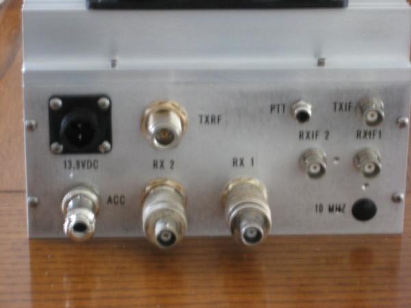
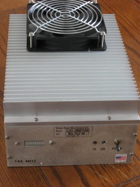
9 Down East Microwave dual-rx Transverter
10 Down East Microwave dual-rx Transverter At the 2010 International EME Conference DEMI offered to make a custombuild dual-rx transverter that I asked about earlier in the year. The prototype dual-rx transverter would be a beta-test for DEMI. The transverter is based their new 2010 L-series design. It was designated L144-28HP DRX. The second Rx was created from a cut-down transverter pc board. A custom enclosure was made to accommodate the extra footprint of adding extra coax connectors. I chose the 50w model to directly drive my 8877 linear amplifier. Full test specs are on my website: The dual-rx in the transverter are fed by two identical preamps made by WA2ODO that exhibit extremely low NF.
11 Hardware of the Dual-Pol Adaptive System
12 Hardware of the Dual-Pol Adaptive System Audio output of the K3 is limited to a maximum bandwidth of 4-KHz. My objective is to use MAP-65 (a variant of JT-65) at 90-KHz of bandwidth. Another limitation is the K3 does not provide access to the I-Q signals. A different approach suggests using the MHz 1 st -IF of the K3 to feed an external SDR which would offer I-Q output. The LP-Pan, made by Telepost, inc., is perfect since it is specifically designed to operate from the 1 st IF of the K3. The LP-Pan was intended to be used as a panadaptor but is a simple SDR and provides both I and Q at audio baseband for input to a stereo soundcard. For the dual-receiver system two LP-Pan are required one for the main K3 receiver IF and one for the K3 sub-receiver IF. But two modifications were required: 1. Access to the IF of the sub-receiver in the K3 2. Running both LP-Pan from a single master LO
: http://www.telepostinc.com/lpan.html The I and Q audio outputs are connected to a four port soundcard.")
13 Hardware of the Dual-Pol Adaptive System The IF simply requires use of a.001 uf coupling capacitor and a run of RG-174 to a BNC connector on the back of the K3. I disabled the LO of one LP-Pan and ran both from the LO in the other LP-Pan (see diagram): The I and Q audio outputs are connected to a four port soundcard. I chose the M-Audio Delta-44 which can support 96 KHz bandwidth.
14 Software of the Dual-Pol Adaptive System Two programs are used: 1. LINRAD 2. MAP-65 Linrad performs the SDR operation of digital filtering, and displaying a spectrum and waterfall screen. Linrad is also able to take the input of the two Rx and computes the vector angle of polarization which is displayed and also peaks the output accordance with that polarity, completely eliminating polarity loss.
15 Software of the Dual-Pol Adaptive System Linrad is the creation of Leif Asbrink, SM5BSZ. Originally written in Linux it is now available in windows. MAP-65 is a variation on the popular digital-eme mode, JT-65. This is the creation of Joe Taylor, K1JT. Joe has produced a suite of digital modes called WSJT. Linrad performs the SDR processing to provide any mode: CW, SSB. AM, FM, etc. For use with MAP-65 (or JT-65) Linrad is run in USB mode. The output data stream is sent to Map-65 for decoding all JT-65 signals in the 90-KHz baseband. MAP-65 is able to discriminate between valid digital signals and interference (birdies). The result is a map of all JT-65 signals listing time, freq., callsign, and signal level for all stations calling within the 90-KHz passband. This is a powerful contest tool and very useful for random eme operation. Two photos follow of my station in different stages of development:

16 Fig. 1 KL7UW, Spring 2011

17 Fig. 2 KL7UW, Summer 2012
18 Addendum I presented a version of this presentation last year at the Pacific NW VHF Society s conference. There are some other hardware approaches: Using the WSE receiver system developed by SM5BSZ (which is out of production so only available used from current owners), and IQ+ which was introduced by HB9DRI this year (a complete 144-MHz dual-receive SDR). I chose my approach before the IQ+ was introduced. My approach provides more versatility as the K3 is fully usable for a wide range of HF and VHF operations, while the other two are fairly limited to VHF/EME pursuits. Being modular, individual modules can be substituted as one desires. The other approaches may perform better and/or be easier to implement. Costs are another factor to consider. Next are some images of Linrad:
19 Fig. 3 Linrad with Adaptive Polarity = 90

20 Fig. 4 Linrad with Adaptive Polarity = 41
21 Fig. 5 Linrad with Adaptive Polarity = 00
22 Fig. 6 Linrad with Adaptive Polarity = Elliptical, 32
23 Recent Changes Introduction of MAP65 vers 2 makes possible running without use of Linrad. This makes setting up software considerably easier. In August, I installed MAP65v2.3 and configured the software to input audio directly into the Delta44 soundcard. MAP65v2.3 has a new look and also processes polarity information without aid of Linrad. If station grid location is available in CALL3.txt file, MAP65 calculates best transmit polarity using both spacial and signal polarity data. Control of the K3 frequency for transmitting requires special software provided by IK7EZN s TRAKBOX program. TRAKBOX reads the azel.dat file created by MAP65 to control VFO-A on the K3 when transmitting. TRAKBOX requires access to the RS-232 port on the K3 for this.
24 TRAKBOX Interfacing
25 Table-I from MAP65 Users Guide (K1JT) *Notes: L = Linrad, S = SDR-Radio, M = MAP65 Input Freq (MHz) SoftRock FUNcube Dongle 28, , 432, 1296 SDR-IQ, Perseus SoftRock 2 IQ+ VL, V, U 28 28, , 144, 432 Polarizations WSE 144 Soundcard Channels Digital Interface Frequency Control* Front-End Software* USB USB USB USB USB Parallel Port L, S, M L, S, M L, S L, M L, M L L or S optional _ L or S required L optional L optional L optional

26 Fig. 7 MAP-65 ver 2.3 Main Window

27 Fig. 6 MAP-65 ver 2.3
28 Closing Remarks MAP65 and Linrad provide enhanced reception of VHF/UHF EME signals by adapting dual-polarity signals to maximize reception by better matching of polarity. MAP65 scans the entire digital sub-band decoding all JT65 signals providing a quick view of activity on the Moon. It is a tremendous asset for contests and precludes using logger chat-style websites for spotting stations. Setup using MAP65v2 makes the installation process considerably easier. My early experience with MAP65 is it improves reception by almost 3-dB, since I no longer have polarity losses. This presentation will be available on my website:
IQ+ XT. 144Mhz SDR-RF Exciter (preliminar v0.1)
") IQ+ XT 144Mhz SDR-RF Exciter (preliminar v0.1) INTRODUCTION Since the IQ+ receiver was introduced one year ago several people ask if I have plans to produce an IQ+ transmitter. Initially I didn't plan
IQ+ XT 144Mhz SDR-RF Exciter (preliminar v0.1) INTRODUCTION Since the IQ+ receiver was introduced one year ago several people ask if I have plans to produce an IQ+ transmitter. Initially I didn't plan
WORKING DX WITH JOE TAYLOR
 WORKING DX WITH JOE TAYLOR By Pete Rimmel N8PR Presented at the Miami Hamfest DX Forum January 31, 2015 SOME OF JOE S PROGRAMS WSJT, MAP65, WSPR, and WSJT-X are all open-source programs designed for
Quest for Optimum Coding and Modulation Schemes for EME
 Quest for Optimum Coding and Modulation Schemes for EME Joe Taylor, K1JT 13 th International EME Conference: Florence, August 8 10, 2008 Ten years of fascination with amateur radio in the 1950s and early
Albert F. Peter AC8GY Aug. 12, 2010
 Albert F. Peter AC8GY Aug. 12, 2010 Software-defined not software-controlled radio Most of the complex signal handling uses DSP User interface through the computer Usually some form of direct conversion
EME with digital modes 144 MHz
 EME with digital modes 144 MHz SM4GGC Stig Larsson Ham radio licensed since 1973 Active on VHF/UHF 1973-1983 and from 2012- EME 1979-1983 and from 2012- Agenda Modes for digital EME WSJT 10 Weak Signal
WSPR (PRONOUNCED WHISPER) Weak Signal Propagation Reporter
 Weak Signal Propagation Reporter") WSPR (PRONOUNCED WHISPER) Weak Signal Propagation Reporter WSPR Uses HF radio with upper sideband capability Computer sound card Internet connection Started in April 2008 Key Folks Joe Taylor, K1JT Developed
WSPR (PRONOUNCED WHISPER) Weak Signal Propagation Reporter WSPR Uses HF radio with upper sideband capability Computer sound card Internet connection Started in April 2008 Key Folks Joe Taylor, K1JT Developed
Using an SDR as a Microwave IF
 Using an SDR as a IF Martlesham Roundtable Nov 2008 Dave Robinson G4FRE Topics Softrock 5 Softrock 6.2 10m TX/RX Softrock 8.3 RX Software SDR1000 SDRIQ HPSDR Elecraft K3 The Future? Basic Software Defined
- Setup and Operation
 - What is JT-65-65 tones sent in 200 HZ bandwidth - Developed for EME - Setup and Operation - Soundcard interface - WSJT-X software (free) - On-Air Demo - PC, Soundcard & Rig Ed Erny - NZ1Q St Petersburg
VHF/UHF Beyond FM Bob Witte KØNR Page 1
 VHF/UHF Beyond FM Technical Coordinator Colorado Section Page 1 Objective The objective of this presentation is to provide an introduction to operating on VHF/UHF, going beyond the usual FM / Repeater
LF Forum. Dave Pick G3YXM David Bowman G0MRF
 LF Forum Dave Pick G3YXM David Bowman G0MRF Timetable Where are we now? Receiver tests Commercial gear Forum Q&A @ Where are we now? Most countries in the world now have access to the bands: 135.7kHz-137.8kHz
Weak Signal Digital Modes. 9V1KG Klaus Aug 2016
 Weak Signal Digital Modes 9V1KG Klaus Aug 2016 Content Introduction What makes these modes so popular? Station setup and interfacing Digital Modulation PSK 31 JT-65/JT-9 PSK Reporter 9V1KG - Weak Signal
Technician License Course Chapter 3 Types of Radios and Radio Circuits. Module 7
 Technician License Course Chapter 3 Types of Radios and Radio Circuits Module 7 Radio Block Diagrams Radio Circuits can be shown as functional blocks connected together. Knowing the description of common
AfedriNet Review. SDRZone. AfedriNet SDR Review
 AfedriNet Review SDRZone AfedriNet SDR Review December 31st 2013 Reviewed by NI0Z AFEDRI SDR-Net http://www.afedri-sdr.com/ Downloads & Manuals http://www.afedri-sdr.com/index.php/downloads AFEDRI SDR-Net
Software Defined Radio. Bella Vista Radio Club 1 February 2018
 Software Defined Radio Bella Vista Radio Club 1 February 2018 Agenda for Software Defined Radio (SDR) What is it? How does it work? Demonstration. How do you hook it up? What hardware is available (Cost)?
Station Automation: Implementation of DX Labs and components
 Station Automation: Implementation of DX Labs and components Hardware requirements: Note that most of benefits of using DX Labs suite of station automation programs can be realized without connecting between
Adding Panoramic Display to my Kenwood TS-2000 Transceiver
 Photo Kenwood Adding Panoramic Display to my Kenwood TS-2000 Transceiver and getting CW Skimmer as a bonus v4 Doug Leach VE3XK TS-2000 with CW Skimmer Photo Elecraft When Rich VE3KI showed me his LP-PAN
What is it? What do I need? How do I use it? Randy Hall K7AGE
 PSK-31 What is it? What do I need? How do I use it? Randy Hall K7AGE First, a little bit about me I was first licensed in 1968 I ve been around video since high school Built a TV camera as high school
Muscle Shoals Amateur Radio Club. Extra License Class Training Session 2
 Muscle Shoals Amateur Radio Club Extra License Class Training Session 2 Review Test Pool Question Review Questions? Syllabus Week 1 9/4/18: Commission s Rules (6 question areas) Week 2 9/11/18: Operating
huprf Panoramic Adaptor Installation FT847
 huprf Panoramic Adaptor Installation FT847 These instructions cover installation of the PAT board in the 1st IF of the FT847 45.705MHz this gives access to all receiver options on the main receiver. A
WSPR: THE WEAK SIGNAL PROPAGATION REPORTER Part 1
 Article first published in the Sep-Oct 2013 issue of The Canadian Amateur WSPR: THE WEAK SIGNAL PROPAGATION REPORTER Part 1 Note: I would like to thank Jay Wilson, W5OLF, for his invaluable assistance
The K290R Project. Steve Kavanagh, VE3SMA, December 2017
 The K290R Project Steve Kavanagh, VE3SMA, December 2017 Background I have been using a pair of Yaesu FT-290R 2m transceivers as IF rigs for microwave transverters for many years. My 2.3, 3.4, 5.7, 10 and
Radio <-> Computer Interfacing. RATS 25-Mar-17 Rob G2FGT
 Radio Computer Interfacing RATS 25-Mar-17 Rob G2FGT Disclaimer! I m no good at home brew this is not about how to build an interface no DIY advice I just want to operate radios, make contacts this
This paper appeared in the Proceedings of the 2002 Central States VHF Society Conference, and of the 2002 Prague EME Conference.
 This paper appeared in the Proceedings of the 2002 Central States VHF Society Conference, and of the 2002 Prague EME Conference. The Weak-Signal Capability of the Human Ear Ray Soifer, W2RS Much attention
Software Defined Radio! Primer + Project! Gordie Neff, N9FF! Columbia Amateur Radio Club! March 2016!
 Software Defined Radio! Primer + Project! Gordie Neff, N9FF! Columbia Amateur Radio Club! March 2016! Overview! What is SDR?! Why should I care?! SDR Concepts! Potential SDR project! 2! Approach:! This
What is it? What do I need? How do I use it? Randy Hall K7AGE
 PSK-31 What is it? What do I need? How do I use it? Randy Hall K7AGE First, a little bit about me I was first licensed in 1968 I ve been around video since high school Built a TV camera as high school
DESIGN, SETUP AND OPERATION CLALLAM COUNTY AMATEUR RADIO CLUB MAY 9, 2018 BILL PETERSON K7WWP
 DESIGN, SETUP AND OPERATION CLALLAM COUNTY AMATEUR RADIO CLUB MAY 9, 2018 BILL PETERSON K7WWP FT8 DESIGN AUTHORS Joe Taylor K1JT Professor of Physica (Emeritus) Princeton University Nobel Prize winner
AN INTRODUCTION TO VHF/ UHF PROPAGATION. Paul Wilton, M1CNK
 AN INTRODUCTION TO VHF/ UHF PROPAGATION Paul Wilton, M1CNK OVERVIEW Introduction Propagation Basics Propagation Modes Getting Started in 2m DX INTRODUCTION QRV on 2m SSB since Aug 1998, on 6m since Jan
HAM RADIO. What s it all about?
 HAM RADIO What s it all about? ELCTROMAGNETIC SPECTRUM LF Low Frequency 30 khz to 300 khz One Ham Band soon MF Medium Frequency 300 khz to 3 MHz. Two Ham Bands ( 160 m + one soon). HF High Frequency 3
Amateur Radio License. Propagation and Antennas
 Amateur Radio License Propagation and Antennas Todays Topics Propagation Antennas Propagation Modes Ground wave Low HF and below, ground acts as waveguide Line-of-Sight (LOS) VHF and above, radio waves
Software Defined Radio in Ham Radio Dennis Silage K3DS TS EPA Section ARRL
 Software Defined Radio in Ham Radio Dennis Silage K3DS silage@arrl.net TS EPA Section ARRL TUARC K3TU SDR in HR The crystal radio was once a simple introduction to radio electronics and Amateur Radio.
Amateur Microwave Communications. Ray Perrin VE3FN, VY0AAA April 2010
 Amateur Microwave Communications Ray Perrin VE3FN, VY0AAA April 2010 Introduction Microwaves are the frequencies above 1000 MHz More than 99% of the radio amateur frequency allocation is in the microwave
About the HDSDR software operations for the IC-R8600
 About the HDSDR software operations for the IC-R8600 These instructions describe how to use the HDSDR software. Before reading this guide, please read How to use the IC-R8600 as an SDR receiver that can
HF Receivers, Part 2
 HF Receivers, Part 2 Superhet building blocks: AM, SSB/CW, FM receivers Adam Farson VA7OJ View an excellent tutorial on receivers NSARC HF Operators HF Receivers 2 1 The RF Amplifier (Preamp)! Typical
Weak Signal Propagation Reporter (WSPR) A M AT EUR EXTRA, CHEROKEE A M AT EUR R A DIO SOCIETY
 A M AT EUR EXTRA, CHEROKEE A M AT EUR R A DIO SOCIETY") Weak Signal Propagation Reporter (WSPR) MAT T PESCH-KK4NLK A M AT EUR EXTRA, CHEROKEE A M AT EUR R A DIO SOCIETY FEBRUARY 11, 2017 What is WSPR? WSPR or Weak Signal Propagation Reporter is a digital protocol
Weak Signal Propagation Reporter (WSPR) MAT T PESCH-KK4NLK A M AT EUR EXTRA, CHEROKEE A M AT EUR R A DIO SOCIETY FEBRUARY 11, 2017 What is WSPR? WSPR or Weak Signal Propagation Reporter is a digital protocol
Current Solar Cycle Poor propagation No propagation Checking HF propagation. Coping with poor HF propagation Q&A
 Topics Current Solar Cycle Poor propagation No propagation Checking HF propagation Predictive (HF propagation prediction software) Empirical (beacons, WSPR, PSKREPORTER and operator testing) Coping with
Software Defined Radio A Closer Look. A Ham Comp Presentation by John Brock ZS6WL Originally 13:00 (C)
") Software Defined Radio A Closer Look A Ham Comp Presentation by John Brock ZS6WL Originally 2011-20-22 @ 13:00 (C) 2018-02-27 Software Defined Radio A Closer Look SDR What is it? The 'Simplest' Design
Software Defined Radio A Closer Look A Ham Comp Presentation by John Brock ZS6WL Originally 2011-20-22 @ 13:00 (C) 2018-02-27 Software Defined Radio A Closer Look SDR What is it? The 'Simplest' Design
Icom IC-9100 HF/VHF/UHF transceiver
 263 Walsall Road, Great Wyrley, Walsall, WS6 6DL Established 1997. Open Monday - Friday 9am - 5pm and Saturday 9.30am - 4pm Tel: 01922 414 796 Fax: 01922 417829 Skype: radioworld_uk Icom IC-9100 HF/VHF/UHF
Software Defined Radios
 Software Defined Radios What Is the SDR Radio? An SDR in general is a radio that has: Primary Functionality [modulation and demodulation, filtering, etc.] defined in software. DSP algorithms implemented
Transceiver selection and Specs.
 Transceiver selection and Specs. Transceivers 1956-2018 From TUBES to SDR Covers 20-10 meters in 100Khz segments, 10 available, crystal needed for each. Plug in crystal holder. 100 Watts output, final
Linrad: New Possibilities for the Communications Experimenter, Part 2
 Linrad: New Possibilities for the Communications Experimenter, Part 2 From the Analog World into the Digital: How do we get the desired signal from RF to the sound card? By Leif Åsbrink, SM5BSZ Linrad
UNDERSTANDING DOPPLER SHIFT: CRITICAL KNOWLEDGE FOR SUCCESSFUL EME ON THE HIGHER BANDS by Al Katz K2UYH
 UNDERSTANDING DOPPLER SHIFT: CRITICAL KNOWLEDGE FOR SUCCESSFUL EME ON THE HIGHER BANDS by Al Katz K2UYH Abstract: This paper discusses the shift in signal frequency caused by the Doppler
by Cliff Pulis, KE0CP SDR Presentation - Cliff Pulis, KE0CP 1
 by Cliff Pulis, KE0CP SDR Presentation - Cliff Pulis, KE0CP 1 Basic Receiver Principles Mixing Frequencies Hetrodyn ing The IF Amplifier SDR Principles & Quadrature Phase (IQ) VHF / UHF DVB-T Dongle SDR
Antennas and Propagation Chapters T4, G7, G8 Antenna Fundamentals, More Antenna Types, Feed lines and Measurements, Propagation
 Antennas and Propagation Chapters T4, G7, G8 Antenna Fundamentals, More Antenna Types, Feed lines and Measurements, Propagation =============================================================== Antenna Fundamentals
CLOUDSDR RFSPACE #CONNECTED SOFTWARE DEFINED RADIO. final design might vary without notice
 CLOUDSDR #CONNECTED SOFTWARE DEFINED RADIO final design might vary without notice 1 - PRELIMINARY SPECIFICATIONS http://www.rfspace.com v0.1 RFSPACE CloudSDR CLOUDSDR INTRODUCTION The RFSPACE CloudSDR
Working Small Stations on 10 and 24 GHz EME with the help of WSJT
 Working Small Stations on 10 and 24 GHz EME with the help of WSJT Al Ward W5LUA October 19, 2013 Morehead State University Morehead, Kentucky The Bands Band Frequency Range Weak signal work in NA 33 cm
SPECS FEATURES SUPPLIED ACCESSORIES. HF All Band Transceiver
 718 HF All Band Transceiver RX 0.030-29.999999MHz* TX 1.800-1.999999 MHz** 3.500-3.999999 MHz** 7.000-7.300000 MHz 10.100-10.150000 MHz 14.000-14.350000 MHz 18.068-18.168000 MHz 21.000-21.450000 MHz 24.890-24.990000
Yaesu FT-1000MP Mark V and NaP3
 Yaesu FT-1000MP Mark V and NaP3 This paper describes in detail the hardware and software required to implement a full-function panadaptor for the Mark V using NaP3. Illustration 1: Panadaptor in operation
The Icom IC Adam Farson VA7OJ. A New Top-class HF/6m Transceiver. IC-7700 Information & Links
 The Icom IC-7700 A New Top-class HF/6m Transceiver Adam Farson VA7OJ IC-7700 Information & Links Copyright 2008 North Shore Amateur Radio Club NSARC HF Operators IC-7700 1 IC-7700 front panel This is a
Ten-Tec Orion/Orion II Users Manual Addendum Firmware Version V3
 Ten-Tec Orion/Orion II Users Manual Addendum Firmware Version V3 It is very important that you read this document in its entirety before using the V3 firmware. Some features behave differently than they
Noise figure measurements with a AT as a noise source using a PC for Y-factor measurement
 Noise figure measurements with a AT-30511 as a noise source using a PC for Y-factor measurement Joe Jurecka for The North Texas Microwave Society Goals Learn how to measure noise figure without a NF meter
The Icom PCR-1000 as a SDR RF Front End OscarOnline.org David Carr, KD5QGR partially based on a document by Edgar J. Kaiser, DF2MZ
 The Icom PCR-1000 as a SDR RF Front End OscarOnline.org David Carr, KD5QGR partially based on a document by Edgar J. Kaiser, DF2MZ Purpose: Many times when working in software defined radio some means
SDR 4++ Dual Diversity SDR Receiver. Operating Guide. version 1.0
 Cross Country Wireless, 7 Thirlmere Grove, BOLTON, BL4 0QB, UK Email chrism@crosscountrywireless.net Web page http://www.crosscountrywireless.net Telephone +44 (0) 1204 410626 Mobile / Workshop +44 (0)
What are the keys to better weak signal receive performance?
 1 Determinants of receiver sensitivity What are the keys to better weak signal receive performance? One of the greatest advances we have seen in the last few years has been the application of Digital Signal
Preliminary features of the SDR-X receiver SDR-X , PowerSDR Winrad Winrad DDS SFDR SFDR AD995 AD99 1
 Preliminary features of the SDR-X receiver The SDR-X receiver, in its full version is capable of continuously tuning the entire HF spectrum, 6m ( 50-52 MHz) band included. SSB, AM etc. demodulation, bandpass
Using WSPR Mode in WSJT7
 Using WSPR Mode in WSJT7 Joe Taylor, K1JT Quick Start: If you are already familiar with the JT65 mode in WSJT, here s a quick summary of operational differences between the WSPR QSO mode and JT65. 1. WSPR
Adjustment for IC-910H. Adjustment. Adjustment
 for IC-910H 30.2 MHz Level 430MHz 2 nd Lo (60.4MHz) Peak Setting the 60.4MHz Frequency the144mhz 1 st Lo Lock Voltage th430mhz 1 st Lo Lock Voltage 144MHz RX Peak/ Gain Band Peak Band Total Gain Sub- Band
Evolution of the WSJT Digital Modes
 Evolution of the WSJT Digital Modes Mike Hasselbeck WB2FKO New Mexico TechFest 25 February 2017 WSJT: A software package for digital radio communication Weak Signal communication by Professor Joe Taylor
NASHUA AREA RADIO CLUB TECH NIGHT SOFTWARE DEFINED RADIOS MARCH 8 TH, 2016
 NASHUA AREA RADIO CLUB TECH NIGHT SOFTWARE DEFINED RADIOS MARCH 8 TH, 2016 Software Defined Radios (SDRs) Topics for discussion What is an SDR? Why use one? How do they work? SDR Demo FlexRadio 6000 Series
Technician License Course Chapter 2. Lesson Plan Module 3 Modulation and Bandwidth
 Technician License Course Chapter 2 Lesson Plan Module 3 Modulation and Bandwidth The Basic Radio Station What Happens During Radio Communication? Transmitting (sending a signal): Information (voice, data,
A Simple SO2R Contest Station
 Andrew Roos, andrew.roos@mweb.co.za June 2007 A Simple SO2R Contest Station Figure 1 - The SO2R Operating Position at SO2R stands for Single Operator Two Radio, and describes a single-operator station
My Itinerary to L-Band Moonbouncing... By Bertrand Zauhar, VE2ZAZ
 My Itinerary to L-Band Moonbouncing... By Bertrand Zauhar, VE2ZAZ ve2zaz@rac.ca http://ve2zaz.net VE2ZAZ October 2010 THIS PRESENTATION WHY MOONBOUNCE? THE HISTORY A REAL CHALLENGE THE BANDS HOW SMALL
21st Century Frequency Converters, Transverters and Radios
 21st Century Frequency Converters, Transverters and Radios Andy Talbot G4JNT www.g4jnt.com What we used to build Replace with minimum tuning, wideband integrated solutions Background The mobile phone and
WSJT: Digital Communication in Extreme Conditions
 WSJT: Digital Communication in Extreme Conditions Mike Hasselbeck WB2FKO Socorro Hamfest 15 October 2016 WSJT: A software package for digital radio communication Weak Signal communication by Professor
FT-8 Weak Signal Digital
 FT-8 Weak Signal Digital Rob Hall KV8P kv8p@arrl.net Why are we talking about FT-8? Developed by Steven Frankie (K9AN) and Joe Taylor (K1JT) and offered in mid- 2017, FT-8 took off where JT-65 and JT-9
July 27, 2016 Class By Israel AD7ND & Andy K3WYC
 TBARC Programs Digital Modes Class July 27, 2016 Class By Israel AD7ND & Andy K3WYC Before We Start This material was put together as an attempt to fulfill a request from the TBARC Board for a digital
Aircraft Scatter on 10 and 24 GHz using JT65c and ISCAT-A
 Aircraft Scatter on 10 and 24 GHz using JT65c and ISCAT-A By VK7MO and David Smith VK3HZ The authors have been using the digital modes JT65C and ISCAT-A to work aircraft scatter at distances of up to 842
FM DISTRIBUTION FOR MOTORWAYS AND TUNNELS
 FM DISTRIBUTION FOR MOTORWAYS AND TUNNELS ADVANTAGES IF COMPARED TO A TRADITIONAL SYSTEM As compared to the traditional analog systems, our innovative solution for FM transmission allows considerable cost
Scalable Ionospheric Analyser SIA 24/6
 Scalable Ionospheric Analyser SIA 24/6 Technical Overview Functional description The ATRAD Scalable Ionospheric Analyser SIA24/6 is designed to observe ionospheric irregularities and their drift in the
PRODUCTS BROCHURE PRODUCTS OVERVIEW
 PRODUCTS BROCHURE WELCOME TO MOUNTAIN RF Mountain RF Sensors is engaged in the design and manufacture of specialty radio frequency (RF) products for government and military customers. The company is geared
Phase Noise and MDS. Paul Wade W1GHZ 2009
 Phase Noise and MDS Paul Wade W1GHZ 2009 w1ghz@arrl.net There has been a lot of noise about phase noise recently, but very little data. We know that older FM rigs with synthesizers sounded terrible on
4GHz / 6GHz Radiation Measurement System
 4GHz / 6GHz Radiation Measurement System The MegiQ Radiation Measurement System (RMS) is a compact test system that performs 3-axis radiation pattern measurement in non-anechoic spaces. With a frequency
Venue 2 TECHNICAL DATA. Six Channel Modular Receiver. Digital Hybrid Wireless. Featuring Digital Hybrid Wireless Technology
 Venue 2 Six Channel Modular Receiver Featuring Digital Hybrid Wireless Technology TECHNICAL DATA 3-block tuning for up to 76 MHz and 3072 synthesized UHF frequencies per receiver module Six-channel modular
The Real FT8, JT65, and JT9 Signal - to - Noise Rato Revealed
 The Real FT8, JT65, and JT9 Signal - to - Noise Rato Revealed Jim Frazier, KC5RUO kc5ruo@arrl.net Introducton You may receive a negative FT8, JT65, or JT9 digital HF communications mode Signal-to-Noise
Module 8 Theory. dbs AM Detector Ring Modulator Receiver Chain. Functional Blocks Parameters. IRTS Region 4
 Module 8 Theory dbs AM Detector Ring Modulator Receiver Chain Functional Blocks Parameters Decibel (db) The term db or decibel is a relative unit of measurement used frequently in electronic communications
ELEC RADAR FRONT-END SUMMARY
 ELEC Radar Front-End is designed for FMCW (including CW) radar application. The output frequency of each RX provides range, speed, and amplitude information to DSP. It will detect target azimuth angle
Using a Software Defined Radio As a Panadapter
 Using a Software Defined Radio As a Panadapter by Dave Core, K8WDA Presented to the Northern Kentucky Amateur Radio Club by Dave Core, K8WDA, on Oct. 9, 2017. What Is a Panadapter? Panadapter aka: Panoramic
Single Conversion LF Upconverter Andy Talbot G4JNT Jan 2009
 Single Conversion LF Upconverter Andy Talbot G4JNT Jan 2009 Mark 2 Version Oct 2010, see Appendix, Page 8 This upconverter is designed to directly translate the output from a soundcard from a PC running
SATELLITES WITH A COLLINEAR ANTENNA
 SATELLITES WITH A COLLINEAR ANTENNA Juan Antonio Fernández Montaña EA4CYQ Radio amateurs have not yet been able to cross the Atlantic Ocean in the high bands (145 MHz up), but we have to say in terrestrial
HF Receivers, Part 3
 HF Receivers, Part 3 Introduction to frequency synthesis; ancillary receiver functions Adam Farson VA7OJ View an excellent tutorial on receivers Another link to receiver principles NSARC HF Operators HF
Beta-test ED1 PCB installed in I0CG s K1
 K1 SSB Modification (Ed.2) This description provides the receiver (RX) modifications, assembly, alignment and operation as a first step. In a second step you can add the remaining transmitter (TX) modifications,
HF Transceiver Codan NGT SR. HF Transceiver Codan NGT SR
 HF Transceiver Codan NGT SR HF Transceiver Codan NGT SR Deliveries of this equipment are stopped HF Emetteurrécepteur Codan NGT SR (86 kb) HF Transceiver Codan NGT SR The NGT SR is a comprehensive solution
UADC4 Universal Analog to Digital Converter for Zero IF Software Defined Radios
 UADC4 Universal Analog to Digital Converter for Zero IF Software Defined Radios INTRODUCTION Zero IF receivers or Direct Conversion Receivers (like SoftRocks, IQ mixers, WSE converters and IQ+ receivers)
35th Eastern VHF/UHF Conference 2009
 35th Eastern VHF/UHF Conference 2009 Enfield, Connecticut, USA 17-19 April 2009 Volume 1 of 2 ISBN: 978-1-61567-185-4 Printed from e-media with permission by: Curran Associates, Inc. 57 Morehouse Lane
Modification Details.
 Front end receiver modification for DRM: AKD Target Communications receiver. Model HF3. Summary. The receiver was modified and capable of receiving DRM, but performance was limited by the phase noise from
Now cover 1296 MHz. TransFox Highlights
 Now cover 1296 MHz TransFox Highlights General coverage 1-1450 MHz Outstanding LO resolution (1Hz), phase noise & lock times thanks to SynFox technology Brings unique VHF, UHF and SHF coverage to SDR SDR
ICOM IC-R8600 Specifications, Features & Options
 General Frequency coverage IC-R8600 USA: 0.010000 821.999999MHz*, 851.000000 866.999999MHz, 896.000000 3000.000000MHz (*Guaranteed range: 0.100000 821.999999MHz) Antenna connector Frequency stability Mode
RSP family of Full Featured Wideband SDR Receivers
 RSP family of Full Featured Wideband SDRuno SDR receivers What is an SDR? A radio communication system where components that have been traditionally implemented in hardware (e.g. mixers, filters, amplifiers,
Ham Radio Training. Level 1 Technician Level. Presented by Richard Bosch KJ4WBB
 Ham Radio Training Level 1 Technician Level Presented by Richard Bosch KJ4WBB In this chapter, you ll learn about: What is a radio signal The characteristics of radio signals How modulation adds information
LnR Precision, Inc. 107 East Central Avenue, Asheboro, NC
 LD5 CW/SSB QRP Transceiver Quick guide manual Description: At the development base of the digital signal processing unit, an algorithm is embedded for IQ processing of the channels with phase suppression
Test of the Large Signal Behaviour of some 144 MHz Radios
 Test of the Large Signal Behaviour of some 144 MHz Radios DF9IC & DARC OV Durlach A35-27. 2. + 19. 3. + 23. 7. 2005 in Pforzheim / Germany Disclaimer: this web page expresses the personal opinion of the
ELECRAFT KX3 EXTENDED VFO TEMPERATURE COMPENSATION PROCEDURE Copyright 2012 Elecraft LLC Rev. A9, November 14, 2012
 ELECRAFT KX3 EXTENDED VFO TEMPERATURE COMPENSATION PROCEDURE Copyright 2012 Elecraft LLC Rev. A9, November 14, 2012 Introduction The KX3 standard VFO temperature compensation is entirely adequate for most
Signal Hound USB-SA44B 4.4 GHz Spectrum Analyzer and USB-TG44A Tracking Generator
 Signal Hound USB-SA44B 4.4 GHz Spectrum Analyzer and USB-TG44A Tracking Generator Reviewed by Phil Salas, AD5X ad5x@arrl.net The tremendous improvements in digital signal processing (DSP) technology and
5G Multi-Band Vector Transceiver
 SOLUTION BRIEF Streamlining high-volume test of 5G NR base stations 5G Multi-Band Vector Transceiver Compact, scalable solution accelerates deployment of 5G equipment 5G New Radio (NR) network equipment
Welcome to Ham Radio 101 & 201
 Welcome to Ham Radio 101 & 201 Sponsored by HF Operating David W6DTW Sponsored by Basic Bands and Propagation New Bands! 630 meters 2,200 meters Requires application and approval Basic Bands and Propagation
A SDR-based receiver for Es hail-2 and the BACAR 6, 10 GHz beacons 30 July 2018
 A SDR-based receiver for Es hail-2 and the BACAR 6, 10 GHz beacons 30 July 2018 Hannes Coetzee, ZS6BZP Introduction If all goes according to plan the Qatar Satellite Company (Es hailsat) will place its
NXDN Signal and Interference Contour Requirements An Empirical Study
 NXDN Signal and Interference Contour Requirements An Empirical Study Icom America Engineering December 2007 Contents Introduction Results Analysis Appendix A. Test Equipment Appendix B. Test Methodology
The VK3UM Radiation and System Performance Calculator
 The VK3UM Radiation and System Performance Calculator 1. Disclaimer... 2 2. Background... 2 3. Calculations... 2 4. Features... 2 5. Default Parameters... 3 6. Parameter Description... 4 7. On Axis Exclusion
WSPR. Raspberry Pi. and the. Scotty Cowling, WA2DFI TAPR/ARRL Digital Communications Conference September 2016, St Petersburg, FL
 WSPR and the Raspberry Pi Scotty Cowling, WA2DFI 2016 TAPR/ARRL Digital Communications Conference September 2016, St Petersburg, FL WSPR and the Raspberry Pi It is pronounced WHISPER And we do monkey around
UADC4. Universal Analog to Digital Converter for Zero IF Software Defined Radios. (pre- launch during the AMSATSA Symposium 2018)
") UADC4 Universal Analog to Digital Converter for Zero IF Software Defined Radios (pre- launch during the AMSATSA Symposium 2018) INTRODUCTION Zero IF receivers or Direct Conversion Receivers (like softrocks,
UADC4 Universal Analog to Digital Converter for Zero IF Software Defined Radios (pre- launch during the AMSATSA Symposium 2018) INTRODUCTION Zero IF receivers or Direct Conversion Receivers (like softrocks,
Working the Low Earth Orbit Satellites III
 North Richland Hills ARC Working the Low Earth Orbit Satellites III NRHARC 10/26/15 Why Satellites? All Ham Classes can use Limited HOA impact Relatively inexpensive (FM) Dual Band Wouxon/Baofeng Handheld