[Originally Prepared by A. L(Lloyd). Butler - December 1, 1961] [Regenerated in HTML by Lloyd Butler - November, 2010] SUMMARY
|
|
|
- Louisa Garrison
- 6 years ago
- Views:
Transcription

1 HIGH FREQUENCY MOBILE TRANSCEIVER WEAPONS RESEARCH ESTABLISHMENT TYPE 2 INSTRUCTION HANDBOOK [Originally Prepared by A. L(Lloyd). Butler - December 1, 1961] [Regenerated in HTML by Lloyd Butler - November, 2010] SUMMARY The following notes have been prepared to provide guidance to Woomera Maintenance staff in the field testing of pilot models of the Type 2 Transceiver manufactured in WRE workshops. They should also provide guidance to the type of handbook required for the production models manufactured by A.W.A. TABLE OF CONTENTS 1.GENERAL SPECIFICATION 1.1 General 1.2 Transmitter 1.3 Receiver 1.4 Valve and Semi-conductor complement 2. OPERATING INSTRUCTIONS 2.1 Operating Channels 2.2 Use of Aerials 2.3 To Receive Signals 2.4 To send Signals 2.5 To Receive Broadcast Programmes and Time Signals 2.6 Switching off 3. CIRCUIT DESCRIPTION 3.1 Transmitter The Crystal Oscillator The Buffer Amplifier The Power Amplifier The Aerial Loading Circuit Metering 3.2 High Tension Power Supply 3.3 Modulator and Speech Amplifier 3.4 Receiver R.F. Amp. and Converter. Stages I.F. Amplifier Stages
2 nd Detector and Automatic Volume Control Beat Frequency Oscillator Audio Amplifier Stages 3.5 Switching and Transmit-Receive Facilities 3.6 Reverse Battery Protection 3.7 Remote Operation 4. INSTALLATION 5. SETTING UP THE TRANSMITTER 5.1 Loading the transmitter to the aerial Whip Aerial Long Wire Aerial 6. SETTING UP THE RECEIVER CRYSTAL LOCKED 7. RECAUTIONS IN SERVICING AND OPERATION 8. SERVICING NOTES AND MEASUREMENTS 8.1 Analysis of Sectional circuit sensitivity RF & I.F. Sensitivities - Receiver Audio Sensitivities - Receiver Speech Amplifier Sensitivity 8.2 Voltage Analysis 8,2.1 Receiver 8,2,2 Transmitter Modulator H.T. Power Supply 9. RECEIVER ALIGNMENT 9.1 I.F. Stages 9.2 RF Stages Location of coils and Trimmers Band 1 - Broadcast Bc/s Band Mc/s Band Mc/s Locking Adjustments Centre Tracking points 10. ADJUSTMENT OF MODULATOR AND SPEECH AMPLIFIER Adjustment Modulator Collector Current Adjustment. of Modulator Level and Performance checks 11. APPENDIX I - Neutralisation check of Amplifiers 12. SOME COMPONENT LAYOUT PICTURES 13. OTHER REFERENCES LIST OF DIAGRAMS Drawing C4788 (7 sheets) - Schedule of Components Drawing C4078 (sheets 2 to 18 ) - Electrical Parts List Drawing C4078 (sheet 1) - Circuit Diagram On Line Circuit Diagram
3 1. GENERAL SPECIFICATION 1.1 General (a) Physical Size - 16" wide a 10.25" deep x 8" high (8.25" high with anti-vibration mounts). (b) Weight - 40 lbs. (c) Dustproof providing front cover is in place and cable entry holes are filled. (d) Not suitable for mounting without outside protection from weather. (e) Remote control facilities - Remote microphone with press to talk facility. Also remote speaker extension. (f) Temperature Range - MINUS 10 C to PLUS 70 C with some reduction of efficiency at higher temperatures. (g) Maximum Storage Temperature 75 C. (h) Power Source - 12 volt battery supply (NOTE POSITIVE EARTH ONLY). (i) Battery load - Receive only - 18 ma (quiescent operation) Receive & Transmit (Standby) A Transmit Speech - 5A (Modulator quiescent) Transmit Speech - 6A (100% modulation) Transmit C.W.- 4.5A 1.2 Transmitter (a) Frequency Range to 12 Mc/s (b) Operating channels - switched, all pretunable between 2.5 to 12 Mc/s. (c) Mode of Transmission - Radio Telephony or Radio Telegraphy (C.W.) (d) R.F. Output Power - 12 watts. (e) Aerial system - Preset operation for each channel for both whip and 0.25 wave long wire. (f) Overall frequency Response c/s to 2500 c/s +/- 2db. Response falls sharply below 400 c/s and above 2500 c/s. (g) Noise level below 50% modulation at 1000 c/s, db. (h) Harmonic Distortion 50% modulation 1000 c/s - 5%. (i) Crystals - D type - 20 pf circuit capacity 1.3 The Receiver (a) Frequency Range to 1600 Kc/s, 2.5 to 20 Mc/s tunable, plus two crystal locked channels each within the range of 2.5 to 12 Mc/s. (b) Intermediate Frequency Kc/s. (c) Mode of Reception - Radio Telephony or Radio Telegraphy (C.W.) - Beat Frequency Oscillator fitted. (d) Overall Sensitivity (1) H.F. Bands - In the region of 1 micro- volt to the aerial via a 50 ohm source to give 50 mw audio output with a signal to noise ratio of 6 db at 25 C. (2) Broadcast Band - 2 to 5 microvolts to the aerial via a 50 ohm source to give 50 mw audio output with a signal to noise ratio of 6db at 25 C. (e) Bandwidth - Approx. 5 Kc/s at 3 db points. (f) Image Ratio KHz - 30 db MHz - 40 db - 12 Mc/s - 20 db - 18 MHz - 16 db - 20 Mc/s - 4 db (g) AVC Characteristic 1 microvolt to 1000 microvolts - 3 db change in audio output level. - 1 microvolt to 100 millivolts - 10dB change in audio output level. (h) Aerial Circuit input impedance suitable for ohms aerial. (i) Beat Frequency Oscillator Variable 7500 c/s c/s. (j) H.F. Oscillator Temperature stability (Temp. Range 20 C to 70*C). H.F. Bands Tunable - Less than 1% shift Broadcast Band - 3 to 5% shift Crystal locked - Less than 0.01% shift (k) Max. audio output 290 mw into 3.5 ohm load at 1000 c/s. (l) Distortion audio amplifier - 5% at 150 mw 1000 c/s. (m) Crystal D type Circuit capacity - 20pf 1.4 Valve & Semi-conductor complement Transmitter 1. 6AU6WA, or CV AQ5W, or CV4019, or E26 Modulator
4 2. OC45 1. OC N301 H.T. Power Supply 2. 2N OA210 Receiver 3. OC OC45 1. OC44 2 OA OC71 2. OC72 1. HC7002 L.T. Circuit 1. OA31 OPERATING INSTRUCTIONS 2.1 Operating.Channels A plate on the front panel of the unit is provided to indicate the frequency of the transmitter operating channels and the locked frequency receiver channels that are available for use. For stationary operation either the tunable section of the receiver or the locked channels may be used, but during mobile operation it is essential to receive on the locked channels. The correct channel to use is determined by previous arrangement with the base stations and depends on the radio network involved, and the variable operating conditions which are effected by the time of the day, the season, and the distance. 2.2 Use of Aerials Whip aerial. The whip is used for mobile operation and for stationary operation where communication is not difficult. The "Aerial Select" switch is turned to the "Whip" position for this aerial. Long wire Aerial. This is used for stationary operation only when communication on the whip is unsatisfactory and improved performance is required. Connect the aerial links for the required frequency as indicated on the aerial reel and tie the end designated "mast" to a high object. The end marked "Transceiver" is connected to the aerial terminal of the transceiver. If a counterpoise wire is also provided, run this out along the ground under the aerial, and connect the end to the earth terminal of the transceiver. When the transceiver is mounted in the vehicle, the counterpoise is not required. The whip aerial feed wire must not be connected when operating on a long wire. For best results the aerial wire should be at right angles to the direction of communication. The "Aerial Select" switch is turned to the "Long Wire" position for this aerial. To Receive Signals Turn the "Power Switch" to either of the following positions :"Rec. only", "Send/Rec. speech", or "Send/Rec. Morse". It is advisable to operate as much as possible in the "Rec only" position as negligible current is drawn from the battery under this condition. The other two positions are only used where the delay in waiting for the transmitter warm up is not permissible i.e. between transmissions during and operating schedule. For frequency locked operation turn the "Receiver Band" switch to either "CHA" or "CHB" as indicated for the required frequency on the plate on the front panel. Set the "Volume" control as is required. For tunable operation turn the "Receiver Band" switch to the required freouency range (position 2 or 3 for communication purposes), and tune the "Receiver Tuning" dial to the correct frequency as indicated on the scale. Adjust the "Volume" control to give a suitable sound level from the loudspeaker and adjust the tuning around the calibrated spot until the signal (if available) is heard. On reception of speech signals the "B.F.O. note" control must be in the "OFF" position. The control can be felt to click into this position when turning extreme anti-clockwise. Unless this is in position, an interfering note will be heard. On reception of morse (C.W.) signals, the "B.F.O. note" control is adjusted to give a suitable pitch. Note. When using the receiver in tunable operation, it may be necessary to transmit first, so that a reply can be received
5 to find the exact spot on the receiver dial. However, to prevent. interference to other stations, it is important that a check is made to see if the channel is clear before transmitting. 2.4 To Send Signals Turn the "Power Switch" to the "Send/Rec. Speech" position for speech operation or the "Send/Rec. Morse" position for morse (C.W.) operation. Allow 30 sections for the transmitter heaters to warm up. The switch is normally left in this position for the duration of the communication schedule. Set the "Transmit Channel" switch to position A,B, or C indicated for the required frequency on the plate on the front panel. Before initial transmission the transmitter tuning must be checked. Unscrew the transmitter tuning lock, press the switch at the right hand of the meter down to the "Tune & Send Morse" position, and adjust the "Transmitter Tuning" control for a minimum meter reading. This should read approximately 70 ma if operating correctly but could vary from 60 to 80 ma depending on the way the aerial is erected and on battery voltage. Screw up the transmitter tuning lock on completion of tuning and restore the switch to the "Receive" position. To send speech, press the button on the microphone which is then ready to accept voice. To restore to receive condition, release the button. Caution The microphone button can be locked on by turning and care should be exercised that this is not accidently turned when pressing. Care should also be taken to ensure that the switch at the right of the meter is left in the "Receive" position otherwise the transmitter will continuously emit a signal. For morse (C.W.) transmission, a morse key with a plug attached is provided. The plug is inserted in the jack designated "Morse Key" at the commencement of the communication schedule. The switch at the right of the meter is used as a send/receive switch for morse operation. The morse key plug must be withdrawn when it is required to send speech or tune the transmitter. 2.5 To Receive Broadcast Programmes and Time Signals When used at long periods for amenities, it is important that the "Power Switch" is left in the "Rec. Only" position to prevent high battery discharge. In this position the current drain feeding the transistor receiver is that small, that it can be ignored. Band switch position 1 (B/Cast) is the normal broadcast band but positions 2 or 3 may be used for short wave broadcast when out of range of the lower frequency stations. Positions 2 and 3 are also used for time signals in the tunable condition of the receiver. The nature of the aerial used is not very important when used for receiving purposes only..6 Switching Off On completion of use of the transceiver, the power switch must be returned to the "OFF" position. 3. CIRCUIT DESCRIPTION 3.1 The Transmitter The transmitter is a three stage three channel crystal controlled unit. Channel change is controlled by a three position switch. All channels can be preset within the range of 2.5 to 12 Mc/s The Crystal Oscillator The oscillator uses a 6AU6WA ruggedised valve as a pierce oscillator. Three crystals are provided under the control of the channel switch. The crystals are "D" type and the crystal circuit capacity is 20 pf. 3.1,2 The Buffer Amplifier This stage gives sufficient power gain from the oscillator to drive the power amplifier. It provides isolation between these two stages and is also used as a keying point for C.W. operation. The valve used is a ruggedised type 6AQ5W. Tuning of the plate circuit is achieved by the adjustment of L201, L202 and L203 respectively for channels A, B and C. Capacitors C214, C215, C216 and C217 can be connected to cover a wave range as required. With the largest condenser C217 connected, the coils can be adjusted to a minimum frequency of 2.5 Mc/s. With no condensers connected, the coils can be adjusted to a maximum frequency of 12 Mc/s.
6 The cathode of the valve is jacked for the manipulating key connection The Power Amplifier This is a 2E26 beam power tetrode. Approximately 350 volts of H.T. is applied to this stage and when loaded correctly operates at a cathode current of 70 ma. Under these conditions, 10 to 12 watts is delivered to the aerial. Grid bias is mainly achieved by grid leak resistance R208 but sufficient protective bias is applied to prevent excessive dissipation during key up condition. Protective bias is partly applied from cathode resistance and partly by returning the grid circuit to the 12 volt negative supply line. The P.A. plate is shunt fed to the P.A. tank inductance L205. This reduces the chance of electric shock during adjustment operations. To cover the range of frequencies of 2.5 to 12 Mc/s, the inductance L205 has four plate taps, and two fixed capacitors C220 and C221 are provided. If connected as specified, the tank Q will remain quite near to optimum value over the frequency range. The P.A. is resonated by tuning C219. This variable capacitor is sufficiently small to prevent the operator from finding an unwanted harmonic once the taps are preset correct The Aerial Loading Circuit Each of the three channels on the transmitter can be preset for correct loading to supply two different aerial systems. The two systems are selected by a switch designated Long Wire/Whip. Tapped loading inductance L206 allows a capacitive aerial to be resonated. If the aerial is inductive capacitors C222, C223, or C224 can be inserted. To resonate the aerial in this case, a capacitor over large is connected and adjustment is again made by adding inductance on L206. As there are six preset aerial loading conditions that can be set up. Six tap leads are provided for L205 and L206 and six connecting posts for the series capacitors to be connected. It is recommended that if a long wire is used it should be a 0.25 wave. In most cases such an aerial will not require series L or C, - L206 will be shorted out and the condensers bypassed. Where more than one frequency is used, one length of aerial with taps at each 0.25 wave point can be provided. The aerial select switch is designated "long wire" for this operation. The "whip" position of the switch is provided for mobile operation on a whip aerial. Under most normal conditions, L206 will always be required to load the whip Metering During normal operation the meter reads P.A. cathode current and is used to indicate resonance dip of the P.A. when adjusting the tuning condenser. A switch is provided inside the unit to connect the meter to read P.A. grid current. This allows tuning of the buffer amp plate circuit inductances for an indication of maximum P.A. grid current. The switch has purposely been made inaccessible to the user to avoid confusion as it is not required once the transmitter has been preset by a technician. A switch on the front panel can be pressed to select battery volts. This has been made non-locking to prevent the user from attempting to tune the P.A. with the meter incorrectly switched The H.T. Power Supply Two 2N301 power transistors are used in a D.C. converter of the saturating core variety connected in a push pull symmetrical arrangement. A simplified explanation of the operation is as follows: The converter is readily made self starting by applying forward bias via divider R401 and R402. Switching on causes random impulses to appear across the various windings of TR401 of such polarities as to increase conduction in one transistor and decrease conduction in the other. The rise of collector current in the first transistor induces a voltage in its associated feedback winding of such polarity as to increase the base potential and further increase the collector current, whilst the fall of collector current in the second transistor induces a voltage in its associated feedback winding of such polarity as to decrease the base potential and further decrease the collector current. The accumulated action causes the first transistor to turn fully on and the second transistor to turn off. The current in the first transistor continues to rise, at a rate determined by the inductance of the primary, until the transformer core saturates and the field collapses. The induced voltages now collapse and a reversed field is set up in the transformer causing regenerative "switch off" of the first transistor and regenerative "switch on" of the second transistor. The second condition will remain until the increase of collector current in the second transistor again causes the core to saturate and cause the field to collapse. The transistors continue to alternate between the two conditions at a frequency determined by the circuit constants and in the order of 400 Kc/s to 500 c/s.
7 The voltage is stepped up in the secondary of TR401 and rectified by four OA201 silicon diodes in a bridge circuit. After filtering, the nominal output voltage is 350 when the transmitter is loaded to a PA - Ik of 70 ma. 3.3 The Modulator and Speech Amplifier The output of the 25 ohm vitavox moving coil microphone is fed direct to the emitter of transistor V301 that is connected in grounded base operation. V302 and V303 amplify the power level suffcient to operate class B modulators V304 and V305. Transistors V301, V302 and V303 are temperature stabilised via D.C. feedback in the emitter circuits. Transistors type OC45 are used in the first two R/C coupled stages in view of their low collector leaking current. This reduces the tendency for collector voltage bottoming so common to R/C coupled stages. The 2N301 Modulator transistors are temperature stabilised by thermistor X301 connected in the base bias circuit. Base bias resistor R322 is adjustable and is set to a point of minimum cross over distortion in the transistors. That corresponds to a total collector current in V304 and V305 of about 60 ma. The output of the modulator is applied to the plate and screen grid of the Power Amplifier V203 and can deliver up to 17 watts of audio at full battery volts. The modulation level is set by potentiometer RV Receiver The receiver is a fully transistorised unit consisting of an RF stage, mixer, separate H.F. oscillator, two I.F. stages and two audio stages. A five position switch SWG provides selection of bands and channels as follows :- Pos to 1600 Kc/s (B/C Band) Pos to 7 Mc/s Tunable Pos. 3-7 to 20 Mc/s Tunable Pos. 4 - CH.A (crystal locked any frequency Mc/s) Pos. 5 - CH.B (crystal locked any frequency Mc/s) 3.4.1;R.F. Amp and Converter Stages The R.F. amp V501, Mixer V502 and oscillator V503 are all drift transistors type OC170. As the impedance of the aerials expected to be used is comparable with the base input impedance of the first transistor, a tap for this purpose is not necessary on the aerial circuit coils and the aerial is connected direct to the base of V501. Base taps only are provided on the aerial coils. Tuning on all tunable bands is achieved with variable 3 gang condenser C501 A B C. Capacitors C530, C531 and C532 provide padding of the oscillator circuit to obtain tracking. In tunable operation the oscillator is the transistor equivalent of the Hartley circuit and its output is injected into the emitter of the mixer transistor from a secondary winding on the oscillator coils. In crystal locked operation the circuit is the transistor equivalent of the Pierce oscillator. The crystals used are "D" type and the crystal circuit capacity is 20 pf. Injection in this case is from collector of the oscillator via capacitor C539 to the input circuit of the mixer. The Locked Channel Aerial and R.F. tuned circuits are preset in their tuning before supply to the user. Coils TR504 and TR509 are set for channel A and coils TR505 and TR510 are set for channel B. To provide a range from 2.5 to 12 Mc/s capacitors C511 to C514 and C523 and C526 are connected in parallel with the coils as is necessary. A large degree of temperature stabilisation is necessary to prevent excessive frequency shift of the oscillator and this is provided by a combination of emitter D.C. feedback from R512 and thermistor (X502) correction in the base bias circuit. Normal emitter D.C. feedback is used on the mixer for stabilisation but the R.F. Amplifier has a special circuit to assist A.V.C. action (refer Paragraph 3.4.3) I.F. Amplifier Stages Two stages of transistors type 0C45 provide most of the gain and selectivity in the receiver. To reduce instability and to give a more symmetrical selectivity curve, the collector to base capacity of both stages are neutralised by capacitors C604 and C610. Normal emitter D.C. feedback is used for temperature stabilisation on V602 but V601 has a special circuit to assist the A.V.C. action (Refer Paragraph 3.4.3). 2nd Detector and Automatic Volume Control
8 Germanium diode MR602 is used for detection of the I.F. signal and the D.C. voltage developed across the load resistor R612 is used to provide automatic volume control to vary the gain of V501 and V601. The base bias divider circuits of V501 and V601 are returned to earth via R612 and the voltage developed across this resistor by rectified signal current is of opposite polarity to the fixed forward bias. As this voltage increases, the forward bias on the base of the transistors is reduced and the base input impedance is increased. This in turn reduces the A.C. signal drive current and thus the overall gain of the stages. To increase the effectiveness of control, the amount of emitter resistance in the controlled stages has been reduced to a very small value. This eliminates most of the D.C. feedback that in a normal temperature stabilised stage would oppose A.V.C. action. To restore temperature stability, thermistors X501 and X601 are connected in the base divider circuit. To further improve the A.V.C action at high signals levels a shunt diode circuit is added. Voltages have been so proportioned that at low signal levels, diode MR601 does not conduct and the junction of R606 and MR601 is slightly positive in respect to the other side of the diode. As transistor V601 is controlled by A.V.C. action, the emitter current will reduce and cause the junction of R606 and MR601 to become more negative until a point is reached where the diode receives reverse polarity and conducts. As the diode is connected to the emitter tap of I.F.transformer TR601 and via C607 to earth, TR601 will be heavily damped to further reduce the signal level Beat Frequency Oscillator V603 is an 0C44 transistor connected in the transistor equivalent of the Colpitts circuit. Injection of this oscillator is via C609 to the base of I.F. amplifier V602. A large amount of D.C. emitter feedback is applied to reduce the amount of frequency change as temperature is increased. B.F.O. on/off and B.F.O. note control is facilitated by combination switch potentiometer SWH/RV601. The switch connects battery to this stage for switch on. The potentiometer RV601 varies the amount of D.C. voltage applied to Silicon Variable Voltage capacitor MR603. This device will vary its capacity from 30 pf when 12 volts of reverse potential is applied, to 130 pf, when the voltage is reduced to 0.1. MR603 is connected across the tuned circuit of the B.F.O. and the change of capacity, under control of the potentiometer, thus varies the frequency of the B.F.O Audio Amplifier Stages The output from the detector is fed via audio volume control RV602 to audio driver stage OC71 - V604. This is transformer coupled to a push pull class B OC72 transistor stage that can supply 290 milliwatts to the 4 inch loudspeaker. Temperature stabilisation in V604 is via emitter feedback. Thermistor X631 stabilises the class B output stage over the temperature range. Emitter resistor R635 protects against thermal runaway at the extreme upper end of the temperature range. 3.5 Switching and Transmit Receive Facilities The main power switch is a 3 pole 4 position unit. The switching is as follows :- Position 1 - OFF Position 2 - REC. ONLY - 12 volts fed to receiver Position 3 - SEND/REC SPEECH - Receive Condition - 12 volts to receiver - Transmit Condition - 12 volts to H.T. power supply - 12 volts to modulator Position 4 - SEND/REC MORSE - Receive Condition - 12 volts to receiver - Transmit Condition - 12 volts to H.T. power supply (Modulator no power) Relay PT is the transmit/receive change over relay and is operated either from the press to talk button on the microphone or from send/rec switch SWE that is used for tuning purposes and for C.W. operation. Contacts PT1, PT2 and PT3 distribute 12 volts to the various sections of the transceiver and contact PT4 is for aerial change over. A D.C. wetting voltage is supplied to the receive aerial contacts via R501 and R102 to break down any oxidisation that may occur. 3.6 Reverse Battery Protection Reverse battery must not be applied to the transceiver. However to protect the transistors against this accident occurring, germanium power diode OA31-MR101 is connected in the non-conducting direction across the load side of battery fuse FS1. Reverse battery causes the diode to conduct heavy current and open the fuse. CAUTION The fuse must not be replaced with any cartridge greater than 7.5 amp rating, as the protection diode could be caused to draw excessive current and be destroyed. 3.7 Remote Operation In mobile installations where it is desired to mount the transceiver in a position not accessible to the operator, the
9 microphone and speaker can be extended. For the microphone, a connector is extended from PLA to an additional connector to fit the microphone socket SKC. For the extension speaker, PLC is removed and replaced with an extension connector via pins 1 and 2. When remote operation is not required, the microphone is fitted on the microphone mount on the front panel of the transceiver and PLA is left in circuit. To fill the cable cut out holes in this case,blank solid rubber grommets replace the ones used for the remote cables. 4. INSTALLATION To mount the transceiver in a mobile vehicle it essential to provide vibration isolation and the four ant-vibration mounts supplied must be used. These are Silent Block Type BPR15 (Folio 5/4694). The only possible exception to this rule is a sedan car that already has good high frequency vibration isolation. The battery cable used should be sufficiently heavy to prevent voltage drop. Miniature Multicore cable type Dumetvin small 16A (3E/1541) should be satisfactory. If the dust seal where the cable enters the transceiver via the rubber grommets is not good, pack with plasticine. It should be pointed out to the user that if the dust seal is to be effective, the front cover must be kept in place as much as possible. In choosing a location on a vehicle for installation, avoid places where high temperatures from the engine, or from the sun, may be encountered. A lead should be run from the earth terminal of the transceiver direct to the vehicle chassis or metal body. Make this as short as possible. When a whip aerial is used, it should be remembered that the lead to the whip is part of the radiator, and must be kept as short as possible. Shielded cable such as coaxial line should not be used. 5. SETTING UP THE TRANSMITTER Select the transmitter crystal the same frequency as the operating frequency. Connect the buffer circuit capacity links for channels A, B or C as required: Frequency Tap Capacity Circuit Ref Mcs A 560 pf C Mcs B 270 pf C Mcs C 120 pf C Mcs B 47 pf C Mcs No Tap Circuit Cap only Connect the PA tank coil L205 fixed taps for channels A, B or C as required : Frequency Tap Turns Mc/s No tap All Turns 4-5 Mc/s A Mc/s B Mc/s C 13 Connect the PA tank circuit capacity for channels A, B or C as required:- Frequency Tap Capacity Circuit Ref Mc/s A 100 pf C Mc/s B 47 pf C Mc/s No Tap Circuit Cap. Only Set the power switch to send/rec. Speech, set the meter switch at the rear. of the front panel to the "grid current" position, and allow heaters of transmitter to warm up. Operate the "Tune & Send Morse" switch and tune the buffer coil slug (L201, L202 or L203) to give maximum reading of grid current on the meter. This should read from 2 to 5 ma (Read the top scale divided by 10). Restore the meter switch at the rear of the front panel to the "cathode current" position. This is the operational position.
10 Check that the P.A. tank circuit resonates by tuning the P.A. tank Condenser for minimum reading on the meter, now showing cathode current. 5.1 Loading the transmitter to the aerial Whip Aerial (Aerial switch. in whip position) Connect link W1, W2, or W3 (for channels A, B or C respectively) to A. This directly joins the aerial loading coil L206 to the coupling taps of L205. Connect the appropriate loading coil tap for the channel concerned at the top of L206. The colour code is : Channel A Orange Channel B Yellows Channel C Green Connect the appropriate coupling tap for the channel concerned a few turns up on L205. Minimum coupling is at the right when viewed from the front of the transceiver. The colour code is the same as for L206. Connect on 0-1 amp R.F. ammeter between the aerial terminal and the whip lead. Resonate the PA tank circuit and adjust the tap on L205 for maximum aerial current. Keep repeating and increase the coupling tap on L206 until all of the following are satisfied:- The P. A. tuning is resonated i.e tuned for a minimum. The loaded P.A. cathode current is in the vicinity of 70 ma. The loading coil is adjusted for maximum aerial current. The ideal is that the P.A. tuning point should be the same both loaded and unloaded. However in practice, the tap points on the coils are not fine enough to often achieve this. If the unloaded tuning point is near one end of the tuning scale, it is also advisable to arrange the tap in L206 so that the tuning point shifts nearer to the centre of the scale when loaded. When more than one channel is to be adjusted, the lower frequency channel should be adjusted first and followed in ascending order to the highest frequency channel. The chassis should also be pushed back into its case for all final settings as the case can cause some detuning. Interaction may also be noticed between channels and the procedure may require repeating several times. If a very high frequency is used and the whip lead is long, the aerial circuit may become inductive. In this case, instead of connecting to tap A, it will be necessary to add capacity by connecting C222, C223 or C224, ( taps B, C or D) to Wi, W2 or W3. Note that if this is used, more capacitive reactance than necessary is added, and the aerial circuit is still adjusted by L Long Wire Aerial (Aerial switch in Long Wire position) It is proposed that where possible, the aerial will consist of tapped sections to provide 0.25 wave lengths for each frequency used. In most cases the aerial will be nominally resistive and the loading coil L206, or the series loading capacitors will not be required. Assuming this to be correct, set up as follows :- Connect link L1, L2, or L3 (for channels A, B or C respectively) to A, i.e. no series capacity. Connect the appropriate loading coil tap for the channel concerned at the top of L206, i.e. no series inductance. The colour code is :- Channel A Black or Blue Channel B Brown Channel C Red Resonate the PA tank circuit and adjust the appropriate tap on L205 until the loaded resonant cathode current is in the vicinity of 70 ma. The colour code is the same as for L206. If the loaded resonant tuning point is not near the unloaded point, or if it tends to tune off the scale, the following may be necessary:- (1)Add turns to L206 if the aerial circuit is capacitive, or,
11 (2)Connect capacity if the aerial circuit is inductive, (and adjust as in the case of the whip aerial). The procedure of adjusting in order of frequency, final adjusting within the case, and interaction between channels (as referred to in the whip adjustment), still applies for long wire. Interaction may also occur between long wire and whip adjustments and all settings of both should be rechecked several times. 6. SETTING UP THE RECEIVER CRYSTAL LOCKED A crystal is selected either 455 Kc/s above or 455 Kc/s below the operating frequency. Connect the fixed capacity links on the aerial and R.F. tuned circuits to channel A or channel B taps as required : Frequency Tap Capacity Capacitor aerial tuned circuit M/cs A 470 pf C514 C Mc/s B 240 pf C513 C Mc/s C 120 pf C512 C Mc/s D 33 pf C511 C Mc/s No Tap Circuit Cap. only Capacitor R.F. tuned circuit Connect a signal generator across the aerial terminals and an output meter across the speaker connector. Set the signal generator on modulation and near the operating frequency. Adjust the signal generator frequency for maximum audio output. Adjust the RF coils (TR509 or TR510) and the aerial circuit coils (TR504 or T2505) for maximum audio output. Check that approximately 1 microvolt modulated with 400 c/s at 30% will give an audio output of 50 millivolts with a signal to noise ratio of 6 db. 7. PRECAUTIONS IN SERVICING AND OPERATION (1) Do not connect to reverse battery. (2) Do not operate in the field of other transmitters, particularly if the transceiver receiver is tuned to the same frequency. This operation can cause destruction of the RF amplifier transistor. The fault symptoms are operation normal except for serious loss of sensitivity. (3) Always use a high resistance voltmeter when taking measurements on the transistor circuits. At least 100,000 ohms per volt is recommended. A vacuum tube voltmeter is ideal. Too low a resitance voltmeter apart from giving incorrect readings can sufficiently unbalance biasing circuits to cause collector current overload. (4) Be careful in taking measurements with voltmeter probes. If the base circuit is accidentally short circuited to the collector circuit, the transistor will be destroyed. (5) Where it is necessary to feed an oscillator to various transistor stages for fault tracing, always couple through a small capacitor to provide D.C. isolation. Do not use too large a value as the charge current could be sufficient to ruin a transistor. (6) Do not operate in temperatures above 65 C and do not store in locations above 75 C Sectional circuit sensitivity figures and voltage analysis figures are listed to assist in locating faults. As far as the receiver is concerned, it should be possible to locate the source of the fault by checking stage sensitivity point to point to locate the offending stage. The voltage analysis should then help to locate the faulty component in this stage RF and IF sensitivities (approx. values) All measurements are the A.C. input voltages applied to the stages concerned necessary to give 50 milliwatts of audio output. In each case the voltage is supplied from a 50 ohm generator source through a 0.01 mfd capacitor and the voltage quoted is the source voltage. If a 10 ohm signal generator is used, a 39 ohm resistor is connected in series. The generator is modulated 30% at 400 Kc/s. The receiver volume control is set at maximum. Aerial:
12 HF Bands - 1 microvolt B/C Band 5 microvolts Mixer (V502) Base HF Bands - 3 microvolts B/C Band - 5 microvolts At IF Frequency (455 Kc/s) - 1 microvolt 1st IF amp (V601) Base - 60 microvolts 2nd IF amp (V602) Base millivolts Detector Diode (MR602) Connection to TR millivolts Audio Sensitivities Voltages quoted are the audio input levels at 1000 c/s applied to the stages concerned necessary to give 50 milliwatts of audio output. A 0.5 mfd isolating capacitor is used in each case. Audio driver (V604) Base - 15 millivolts Audio driver (V604) Collector volts If a suitable sensitive instrument is not available to measure the base input audio voltage to V604, the audio signal generator can be applied via a 1000 ohm resistor and a 10 ohm resistor in series and the resistor junction coupled to the transistor base. The voltage can then be measured across the total network and divided by Speech Amplifier sensitivity The overall gain of the speech amplifier and modulator may be checked using the test arrangement specified in paragraph The input level to the speech amplifier, with the control RV301 set for maximum gain, is minus 80 dbm for full modulation with the PA - Ik set at 70 ma. After this test is concluded, RV301 must be reset as outlined in paragraph Voltage Analysis Voltage Analysis Receiver MR602 - Detector diode load. R612 - No signal: -0.1V - 100uV input: +0.06V Voltage Analysis Transmitter (PA - IK Loaded to 70 ma)
13
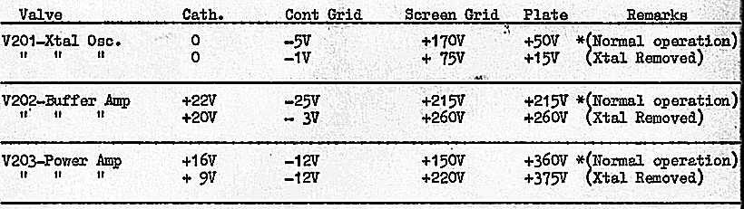
 H.T. output Voltage 380 (Xtal removed) H.T. Total current 95 ma (Transmitter loaded to 70 ma PA - IK) 9.")
14 P.A. IK (Key up condition) = 39ma. * Note. As detuning occurs with measurement, readings are only a guide Voltage Analysis Modulator (No audio input) Voltage Anlaysis H.T. Power Supply Transistor Emitter Base Collector V V +2,5V -12V V V +2.5V -12V H.T. output Voltage 360 (Transmitter loaded to 70 ma PA - IK) H.T. output Voltage 380 (Xtal removed) H.T. Total current 95 ma (Transmitter loaded to 70 ma PA - IK) 9. RECEIVER ALIGNMENT 9.1 I.F. Stages Connect a signal generator tuned to 455 Kc/s to the base of the mixer V502 through a 1000 ohm resistor and a 1000 pf capacitor. Accurately calibrate the signal generator on this frequency against a known accurate signal source such as a heterodyne wavemeter. This is important because if the IF Frequency is not accurate, the receiver will not align correctly in crystal locked condition. Connect an output meter to the speaker output connector and with the RF signal tone modulated, adjust the slugs of TR601, TR602 and TR603 for maximum audio output. Repeat the process until no further improvement is shown. Under normal conditions in the field, neutralisation of the IF stages will not require checking, however, if the receiver is being aligned for the first time following manufacture, or if TR602 or TR603 is changed in the field, this must be checked to ensure that the secondaries of TR602 and TR603 are phased correctly. The effects of incorrect neutralisation are :- Tendency to instability in the IF stages. Asymmetrical selectivity curve. Interaction between tuning of IF transformers. A neutralisation check method is described in Appendix 1 (Paragraph 10). 0n completion of alignment, lock the IF coil slugs with shellac. 9.2 RF Stages Before alignment, check that the dial pointer corresponds to the left hand horizontal line above the Mc/s markings on the dial scale when the tuning gang is set at minimum capacity. At this setting the pointer should be parallel with the top and bottom of the transceiver case. Note that the type of tuning gang used will not quite cover 180 degrees and the dial will not quite rotate to a parallel point at the high capacity end. To eliminate the chance of detuning when the cover is replaced, it is preferable to align the RF stages with a dummy
15 cover in place drilled for access to coils and trimmers Location of Coils and Trimmers In the RF assembly, the location of the various sections are as follows :- Front compartment - Aerial circuit coils and trimmers. Centre compartment - RF circuit coils and trimmers. Rear compartment - Oscillator circuit coils and trimmers. All the coils are designated with their circuit reference and the trimmers are marked 1, 2 or 3 to indicate the Band number. In each compartment, Band 1 coils and trimmers are nearest the front, Band 2 in the centre and Band 3 at the rear. Proceed with alignment in ascending order Band 1, 2 and Band 1 - Broadcast, Kc/s (1) Set the signal generator on 600 Kc/s and adjust TR511 to make the pointer on the tuning dial read 600 Kc/s on the scale. (2) Set the signal generator on 1450 Kc/s and adjust C535 to make the pointer on the tuning dial read 1450 Kc/s on the scale. C535 is the front trimmer in the rear compartment. (3) Repeat 1 and 2 a number of times until both conditions are satisfied. (4) Set the signal generator on 600 Kc/s and adjust TR501 and TR506 for maximum audio output when the receiver is tuned to that frequency. (5) Set the signal generator on 1450 Kc/s and adjust C503 and C516 for maximum audio output when the receiver is tuned to that frequency. C503 and C5I6 are the front trimmers in the front and centre compartments. (6) Repeat 4. and 5 a number of times until no further improvement is noticeable Band to 7 Kc/s (1) Set the signal generator on 2.7 Mc/s and adjust TR512 to make the pointer on the tuning dial read 2.7 Mc/s on the scale. (2) Set the signal generator on 6.3 Mc/s and adjust C537 to make the pointer on the tuning dial read 6.3 Mc/s on the scale. C537 is the centre trimmer in the rear compartment. (3) Repeat 1 and 2 a number of times until both conditions are satisfied. (4) Set the signal generator on 2.7 Mc/s and adjust TR502 and TR507 for maximum audio output when the receiver is tuned to that frequency. (5) Set the signal generator on 6.3 Mc/s and adjust C504 and C517 for maximum audio output when the receiver is tuned to that frequency. C504 and C517 are the centre trimmers in the front and centre compartments. (6) Repeat 4. and 5 a number of times until no further improvement is noticeable Band 3-7 to 20 Mc/s (1) Set the signal generator on 7.7 Mc/s and adjust TR513 to make the pointer on the tuning dial read 7.7 Mc/s on the scale. (2) Set the signal generator on 18 Mc/s and adjust C540 to make the pointer on the tuning dial read 18 Mc/s on the scale. C540 is the rear trimmer in the rear compartment. (3) Repeat 1 and 2 a number of times until both conditions are satisfied. (4) Set the signal generator on 7.7 Mc/s and adjust TR503 and TR508 for maximum audio output when the receiver is tuned to that frequency (5) Set the signal generator on 13 Mc/s and adjust C505 and 0513 for maximum audio output when the receiver is tuned to that frequency. C505 and C518 are the rear trimmers in the front and centre compartments.
16 (6) Repeat 4 and 5 a number of times until no further improvement is noticeable Locking of adjustments All RF coils are fitted with a piece of 1 mm Symel sleeving to prevent the slug working loose. The trimmers should be sealed with a small amount of shellac Centre Tracking Points The centre tracking points should occur near 1025 Kc/s for Band 1, 4.5 Mc/s for Band 2, and Mc/s for Band 3. If there is a serious loss of sensitivity in the centre of the band, the padder condensers C530, C531 and C532 should be suspect. The effect could also be caused by peaking up one end of a band on the image frequency instead of the signal frequency. Note that on the tuning dial, the image frequency should always be higher than the signal frequency. 10. Adjustment of Modulator and Speech Amplifier Adjustment Modulator Collector current Disconnect the centre tap of the primary of modulation transformer TR302 and insert a milliameter in series with the tap and the connecting wire. Set the tap on base bias resistor R322 to give 60 ma collector current. Precaution - To prevent damage to the transistors due to overbias condition, resistor R322 should be initially set at maximum resistance and the tap then gradually shifted until the correct collector current is obtained Adjustment of Modulation Level and performance checks. The gain of the speech amplifier is adjusted by potentiometer RV301. The nominal setting is such that when a 1000 c/s tone is fed to the 50 ohm input at a level of minus 60 dbm, the transmitter, when loaded to a P. A. - Ik of 70 ma, will be modulated 50%. To check specifications for frequency response, noise level,and harmonic distortion, as quoted in paragraphs 1.2 (f), (g) and (h), the speech amplifier is set in this nominal condition. The input is fed from a 600 ohm balanced audio oscillator via a 600 ohm balanced adjustable attenuator and a 600 to 50 ohm transformer. Due to the chance of noise pick up and R. F. feedback, all leads must be shielded and a transformer used with an electrostatic shield to prevent longitudinal effects. The modulation is checked with a suitable modulation monitor. If noise and distortion measurements are to be carried out, the output is coupled to a noise and distortion meter. The final setting of RV301 is dependent on the output level of the microphone and should be set on speech with the particular microphone allocated to the transceiver. This is important as some discrepancy will be found in the output level of various microphones. The speech level is set such that the peaks of speech fully modulate the carrier. This is preferably checked by observing the modulation pattern on a cathode ray oscilloscope rather than using the modulation monitor which may not follow the speech peaks. 11 APPENDIX I Neutralisation Check of IF Amplifiers V601 and V602 A signal generator is required to feed on output of at least 100 millivolts to the secondary of the stage output transformer. This is fed via a 1000 ohm resistor and a 1000 pf capacitor at the IF frequency 455 Kc/s. A detector is also required with at least 40 microvolts, or better sensitivity. This could be an amplifier followed by a C.R.O., a V.T.V.M., or a multimeter. A signal tracer operational on 455 Kc/s with V.T.V.M. fitted is quite a useful instrument for the purpose. The detector is coupled via a 1000 pf capacitor from the base of the stage concerned. The connections for both stages are as follows :- V601 Signal Generator - connect to V602 base Detector - connect to V601 base V602 Signal Generator - connect to the hot side of TR603 secondary Detector - connect to V602 base For the neutralisation check, the converter oscillator must be disabled. This can be achieved by switching to a crystal locked position and removing the crystal. The A.V.C. must also be disabled. This can be achieved by opening one leg of detector diode MR602. To check for correct phasing of the neutralising circuit, neutralising capacitor C604 (for V601), or C610 (for V602), is disconnected. If the detected level rises, then the phasing can be assumed to be correct. If the level falls, the secondary
17 of the output transformer TR602 (or TR603) must be reversed. On completion of the neutralisation check, carry out normal IF alignment procedure. 12. SOME COMPONENT LAYOUT PICTURES Layout 1 Layout 2 Layout 3 Layout OTHER REFERENCES Mobile Radio at the Woomera Radio Range - by Lloyd Butler - Published in "Amateur Radio", Jan. 1988
KWM-2/2A Transceiver THE COLLINS KWM-2/2A TRANSCEIVER
 KWM-2/2A Transceiver Click the photo to see a larger photo Click "Back" button on browser to return Courtesy of Norm - WA3KEY THE COLLINS KWM-2/2A TRANSCEIVER Unmatched for versatility, dependability and
A 100-Watt Transmitter Using a Pair of VT1625s
 12/16/2007 6:00 PM VT1625 100 Watt Transmitter A 100-Watt Transmitter Using a Pair of VT1625s FIG. 10.6 A 100-watt transmitter for five bands, using salvaged TV power transformer and surplus 1625 amplifier
51J-4 COMMUNICATIONS RECEIVER
 51J-4 COMMUNICATIONS RECEIVER Transcribed from 520-5014-00 August 15, 1954 GENERAL DESCRIPTION The Collins 51J-4 Receiver is designed for communication applications where stability and dial accuracy of
Frequency range: BAND RANGE MHz MHz
 INSTRUCTION SHEET NO. 20 POWER-MITE PM3 and PM3A DESCRIPTION The Power-Mite 3 and 3A are self-contained CW transceivers covering 40 and 20 meters. The receiver is compromised of a variable oscillator operating
The Canadian WS 52 was designed and built in Canada by Canadian Marconi. It could be used either as a vehicle set or a ground station.
 THE CANADIAN WIRELESS SET NO 52 Alan Morriss, G4GEN The Canadian WS 52 was designed and built in Canada by Canadian Marconi. It could be used either as a vehicle set or a ground station. The set was intended
Amateur Radio Examination EXAMINATION PAPER No. 275 MARKER S COPY
 01-6-(d) An Amateur Station is quoted in the regulations as a station: a for training new radio operators b using amateur equipment for commercial purposes c for public emergency purposes d in the Amateur
 file:///c /BoatAnchors/Hammarlund/HQ170A/HQ170SVC.TXT Dear OM: This form is being prepared to provide prompt attention to a complaint as a result of trouble that may be experienced in the field. In addition
CON NEX HP. OWNER'S MANUAL Full Channel AM/FM Amateur Mobile Transceiver TABLE OF CONTENTS TUNING THE ANTENNA FOR OPTIMUM S.W.R..
 TABLE OF CONTENTS PAGE SPECIFICATIONS... 2 INSTALLATION... 3 LOCATION... 3 CON NEX - 4300HP MOUNTING THE RADIO... 3 IGNITION NOISE INTERFERENCE... 4 ANTENNA... 4 TUNING THE ANTENNA FOR OPTIMUM S.W.R..
Operation Manual. Model SG Elenco Precision Wide Band Signal Generator
 99 Washington Street Melrose, MA 02176 Phone 781-665-1400 Toll Free 1-800-517-8431 Visit us at www.testequipmentdepot.com Elenco Precision Wide Band Signal Generator Model SG-9000 Operation Manual CONTENTS
KACHINA 1 SSB TRANSCEIVER
 KACHINA 1 SSB TRANSCEIVER THEORY OF OPERATION The Kachina 1 Amateur Band Transceiver is a highly sophisticated, state of the art, piece of communication equipment, housed in the smallest of packages. Yet,
INSTRUCTIONS FOR INSTALLATION AND OPERATION OF THE MEISSNER SIGNAL SHIFTER MODEL EX
 INSTRUCTIONS FOR INSTALLATION AND OPERATION OF THE MEISSNER SIGNAL SHIFTER MODEL EX I. INTRODUCTION A. The MEISSNER SIGNAL SHIFTER is a variable frequency exciter, with output over the entire ranges of
THE 1956 ZENITH ROYAL 500 TRANSISTOR OWL S EYES RADIO.
 THE 1956 ZENITH ROYAL 500 TRANSISTOR OWL S EYES RADIO. Dr. H. Holden. Feb. 2018. Introduction: The Zenith Royal 500 radio appeared in 1956, two years later than the Regency TR1 which was the first commercial
MASTR II AUXILIARY RECEIVER 19D417546G7 & G8 & ANTENNA MATCHING UNITS 19C321150G1-G2. Maintenance Manual LBI-30766L. Mobile Communications
 L Mobile Communications MASTR II AUXILIARY RECEIVER 19D417546G7 & G8 & ANTENNA MATCHING UNITS 19C321150G1-G2 Printed in U.S.A Maintenance Manual TABLE OF CONTENTS Page SPECIFICATIONS.....................................................
Hallicrafters SX-88 Owners Manual
 Hallicrafters SX-88 Owners Manual Images and text excerpted from original Hallicrafters literature. Section 1. General Description The Hallicrafters SX-88 represents the ultimate in precision communications
The G4EGQ RAE COURSE Lesson 9 Transmitters Lesson 8 looked at a simple transmitter exciter comprising of oscillator, buffer and multiplier stages.
 Lesson 8 looked at a simple transmitter exciter comprising of oscillator, buffer and multiplier stages. The power amplifier The output from the exciter is usually very low and it is necessary to amplify
hallicrafters PERFORMANCE SPECIFICATIONS MODEL: SR-2000 LATEST REVISION: 18 JAN 66 Code ident # Specification #
 hallicrafters PERFORMANCE SPECIFICATIONS MODEL: SR-2000 LATEST REVISION: 18 JAN 66 Code ident # 26916 Specification # 093-002154 I. GENERAL A. Power input 117V 50-60 cycles from a source capable of delivering
The KW 76A MOBILE RECEIVER
 The KW 76A MOBILE RECEIVER The KW 76A Receiver is designed primarily for mobile operation. The compact layout makes it particularly suitable for under dash mounting in a vehicle. When used at a Home station
MFJ-219/219N 440 MHz UHF SWR Analyzer TABLE OF CONTENTS
 MFJ-219/219N 440 MHz UHF SWR Analyzer TABLE OF CONTENTS Introduction...2 Powering The MFJ-219/219N...3 Battery Installation...3 Operation Of The MFJ-219/219N...4 SWR and the MFJ-219/219N...4 Measuring
Technician Licensing Class. Lesson 4. presented by the Arlington Radio Public Service Club Arlington County, Virginia
 Technician Licensing Class Lesson 4 presented by the Arlington Radio Public Service Club Arlington County, Virginia 1 Quiz Sub elements T6 & T7 2 Good Engineering Practice Sub element T8 3 A Basic Station
REPAIRING THE RM KL400 LINEAR AMPLIFIER.
 REPAIRING THE RM KL400 LINEAR AMPLIFIER. Les Carpenter G4CNH December 2012 Page 1 of 20 The following is a step by step guide to fixing your KL400 amplifier. Each part will be individually tested up to
To put the Transmitter into operation, the following procedure should be carried out:
 TUNING The KW VANGUARD Transmitter Operating & Tuning Procedure Adjust the three mains voltage selectors at rear of chassis to appropriate voltage. Connect mains lead to A.C. supply (Green is earth). Plug
FREQUENCY AGILE FM MODULATOR INSTRUCTION BOOK IB
 FMT615C FREQUENCY AGILE FM MODULATOR INSTRUCTION BOOK IB1215-02 TABLE OF CONTENTS SECTION SUBJECT 1.0 Introduction 2.0 Installation & Operating Instructions 3.0 Specification 4.0 Functional Description
HAMTRONICS TB901 FM EXCITER INSTALLATION, OPERATION, & MAINTENANCE
 HAMTRONICS TB901 FM EXCITER INSTALLATION, OPERATION, & MAINTENANCE GENERAL INFORMATION. The TB901 is a single-channel low power fm transmitter (exciter) designed to provide 300-600 milliwatts continuous
Amateur Radio Examination EXAMINATION PAPER No. 276 MARKER S COPY
 01-3-(a) The Amateur Service in New Zealand is administered through this prime document: a the New Zealand Radiocommunications Regulations b the Broadcasting Act c the Telecommunications Act d the Radio
A 75-Watt Transmitter for 3 Bands Simplified Shielding and Filtering for TVI BY DONALD H. MIX, W1TS ARRL Handbook 1953 and QST, October 1951
 A 75-Watt Transmitter for 3 Bands Simplified Shielding and Filtering for TVI BY DONALD H. MIX, W1TS ARRL Handbook 1953 and QST, October 1951 The transmitter shown in the photographs is a 3-stage 75-watt
His Master s Voice SERVICE MANUAL FIVE-VALVE VIBRATOR POWERED BATTERY RECEIVERS. fo r. Model 329 Model 359. Dual - Wave Broadcast
 PRIVATE A N D C O N F ID E N T IA L FOR TRADE USE O N L Y His Master s Voice I f SERVICE MANUAL fo r FIVE-VALVE VIBRATOR POWERED BATTERY RECEIVERS Dual - Wave Broadcast Model 329 Model 359 TECHNICAL SPECIFICATION
D ELCO. electronic parts AUTO RADIO BULLETIN. Connect Signal Generator to
 D ELCO electronic parts AUTO RADIO BULLETIN Bulletin 6D-864 Date 10-15-56 Page 1 FIRST ISSUE SUBJECT: SERVICE INSTRUCTIONS - CHEVROLET CUSTOM DELUXE WITH PUSH BUTTON TUNING - MODEL 987575 GENERAL M O U
Definitions of Technical Terms
 Definitions of Technical Terms Terms Ammeter Amperes, Amps Band Capacitor Carrier Squelch Diode Dipole Definitions How is an ammeter usually connected = In series with the circuit What instrument is used
The 144MHz Anglian 3 transverter
 The 144MHz Anglian 3 transverter A high performance 144/28MHz transverter G4DDK document issue 1 12/9/16 Introduction Anglian 3 is an update to the 144MHz Anglian 2 transverter. The Anglian 2 is no longer
A GOOD REGENERATIVE RECEIVER WITH SIMPLE FINE TUNING (2008)
") A GOOD REGENERATIVE RECEIVER WITH SIMPLE FINE TUNING (2008) A good SSB-CW-AM regenerative receiver with a fine tuning by moving the wooden stick with a grounded piece of PCB towards the coil. A good regenerative
A GOOD REGENERATIVE RECEIVER WITH SIMPLE FINE TUNING (2008) A good SSB-CW-AM regenerative receiver with a fine tuning by moving the wooden stick with a grounded piece of PCB towards the coil. A good regenerative
LBI-30398N. MAINTENANCE MANUAL MHz PHASE LOCK LOOP EXCITER 19D423249G1 & G2 DESCRIPTION TABLE OF CONTENTS. Page. DESCRIPTION...
 MAINTENANCE MANUAL 138-174 MHz PHASE LOCK LOOP EXCITER 19D423249G1 & G2 LBI-30398N TABLE OF CONTENTS DESCRIPTION...Front Cover CIRCUIT ANALYSIS... 1 MODIFICATION INSTRUCTIONS... 4 PARTS LIST AND PRODUCTION
The 21st Century R-390A/URR Reference Y2K-R3 Edited 7/09: No Technical Changes Chapter 2 - Operation. Page Table Of Contents 2-1
 Edited 7/09: No Technical Changes Chapter 2 - Operation Page Table Of Contents 2-1 2.1 Introduction. 2-2 2.2 Controls and Indicators 2-2 2.3 Operating Instructions And Control Settings 2-9 2.3.1 Pre-operational
070 ELECTRONICS WORKS EXAMINATION STRUCTURE
 070 ELECTRONICS WORKS EXAMINATION STRUCTURE The trade will be examined under the following components or subject grouping: Electronic Devices and Circuit, Radio Communication and Television. EXAMINATION
PA FAN PLATE ASSEMBLY 188D6127G1 SYMBOL PART NO. DESCRIPTION. 4 SBS /10 Spring nut. 5 19A702339P510 Screw, thread forming, flat head.
 MAINTENANCE MANUAL 851-870 MHz, 110 WATT POWER AMPLIFIER 19D902797G5 TABLE OF CONTENTS Page DESCRIPTION.............................................. Front Page SPECIFICATIONS.................................................
1. What is the unit of electromotive force? (a) volt (b) ampere (c) watt (d) ohm. 2. The resonant frequency of a tuned (LRC) circuit is given by
 volt (b) ampere (c) watt (d) ohm. 2. The resonant frequency of a tuned (LRC) circuit is given by") Department of Examinations, Sri Lanka EXAMINATION FOR THE AMATEUR RADIO OPERATORS CERTIFICATE OF PROFICIENCY ISSUED BY THE DIRECTOR GENERAL OF TELECOMMUNICATIONS, SRI LANKA 2004 (NOVICE CLASS) Basic Electricity,
Department of Examinations, Sri Lanka EXAMINATION FOR THE AMATEUR RADIO OPERATORS CERTIFICATE OF PROFICIENCY ISSUED BY THE DIRECTOR GENERAL OF TELECOMMUNICATIONS, SRI LANKA 2004 (NOVICE CLASS) Basic Electricity,
ERICSSONZ LBI-30398P. MAINTENANCE MANUAL MHz PHASE LOCKED LOOP EXCITER 19D423249G1 & G2 DESCRIPTION TABLE OF CONTENTS
 MAINTENANCE MANUAL 138-174 MHz PHASE LOCKED LOOP EXCITER 19D423249G1 & G2 TABLE OF CONTENTS Page DESCRIPTION... Front Cover CIRCUIT ANALYSIS...1 MODIFICATION INSTRUCTIONS...4 PARTS LIST...5 PRODUCTION
1 TRANSISTOR CIRCUITS
 FM TRANSMITTERS The first group of circuits we will discuss are FM TRANSMITTERS. They can be called SPY TRANSMITTERS, FM BUGS, or a number of other interesting names. They all do the same thing. They transmit
Chapter 3. Electricity, Components and Circuits. Metric Units
 Chapter 3 Electricity, Components and Circuits Metric Units 1 T5B02 -- What is another way to specify a radio signal frequency of 1,500,000 hertz? A. 1500 khz B. 1500 MHz C. 15 GHz D. 150 khz T5B07 --
MODEL FS-4 INSTRUCTION MANUAL R.L. DRAKE COMPANY, MIAMISBURG, OHIO, U.S.A.
 MODEL FS-4 F R E Q U E N C Y S Y N T H E S I Z E R INSTRUCTION MANUAL R.L. DRAKE COMPANY, MIAMISBURG, OHIO, U.S.A. LIMITED WARRANTY R. L. DRAKE COMPANY warrants to the original purchaser that this product
EDACS WALL MOUNT STATION. Maintenance Manual. Mobile Communications LBI-31838A TABLE OF CONTENTS
 A Mobile Communications EDACS WALL MOUNT STATION TABLE OF CONTENTS SYSTEM BOARD & REGULATOR BOARD.......... LBI-31892 KEY/DISPLAY BOARD MAINTENANCE MANUAL.... LBI-31940 Maintenance Manual Printed in U.S.A.
UNITED MOTORS SERVICE AUTO RADIO BULLETIN
 UNITED MOTORS SERVICE DIVISION OF GENERAL MOTORS CORPORATION General Offices - Detroit AUTO RADIO BULLETIN Bulletin 6D-854 Date 11-1-54 Page 1 FIRST ISSUE GENERAL SUBJECT: SERVICE INSTRUCTIONS - 12V CHEVROLET
Copyright 2016, R. Eckweiler & OCARC, Inc. Page 1 of 8
 HOM rev. new Heathkit of the Month: by Bob Eckweiler, AF6C Heathkit of the Month #72 - HW-12/22/32 SSB Transceivers Pt. II AMATEUR RADIO - SWL Heathkit HW-12 / HW-22 / HW-32 Single-Bander SSB Transceivers
MAINTENANCE MANUAL TRANSMITTER/RECEIVER BOARD CMN-234A/B FOR MLSU141 & MLSU241 UHF MOBILE RADIO TABLE OF CONTENTS
 MAINTENANCE MANUAL TRANSMITTER/RECEIVER BOARD CMN-234A/B FOR MLSU141 & MLSU241 UHF MOBILE RADIO TABLE OF CONTENTS DESCRIPTION... 2 CIRCUIT ANALYSIS... 2 TRANSMITTER... 2 9-Voft Regulator... 2 Exciter...
Central Electronics Model 600L Linear Amplifier
 INTRODUCTION This manual has been reproduced by James Lawrence, NA5RC, a 600L owner. Text no longer applicable such as insurance claim with the carrier has been deleted. Some capitalization and grammar
IPR LA-3 KIT last update 15 march 06
 IPR LA-3 KIT last update 15 march 06 PART-2: Audio Circuitry CIRCUIT BOARD LAYOUT: Power and Ground Distribution Now that your power supply is functional, it s time to think about how that power will be
Hendricks QRP Kits BITX20A to BITX17A Conversion Instructions
 Hendricks QRP Kits BITX20A to BITX17A Conversion Instructions 30 November 2008 Converting your BITX20A Kit to a BITX17A Kit is not all that complex. It only requires that you change crystals and some resonance
Maintenance Manual TRANSMITTER/RECEIVER BOARD CMN-233 FOR MLSH041
 Maintenance Manual TRANSMITTER/RECEIVER BOARD CMN-233 FOR MLSH041 TABLE OF CONTENTS Page DESCRIPTION... 2 CIRCUIT ANALYSIS... 2 Transmitter... 2 9-volt Regulator... 2 Exciter... 2 40-Watt PA... 2 Antenna
4X150A/7034 Radial Beam Power Tetrode
 4X15A/734 Radial Beam Power Tetrode T The Svetlana 4X15A/734 is a compact radial beam tetrode. The 4X15A is intended for Class AB SSB linear RF amplifier service. It is intended for stationary and mobile
CHEVROLET RADIO. SERVICE and SHOP MANUAL
 CHEVROLET RADIO SERVICE and SHOP MANUAL 1961 RADIOS 988414-PUSH BUTTON RADIO 988413-MANUAL RADIO 988468-CORVAIR PUSH BUTTON RADIO 988460-CORVAIR MANUAL RADIO 985003-CORVETTE RADIO 985036-MANUAL TRUCK RADIO
bhi bhi DSP Noise Cancelling Products DSP Noise Cancelling Products NEDSP1061-PCB bhi ltd PO Box 318 Burgess Hill West Sussex RH15 9NR
 DSP Noise Cancelling Products bhi bhi ltd PO Box 318 Burgess Hill West Sussex RH15 9NR tel: +44 (0)845 217 9926 fax: +44 (0)845 217 9936 sales@bhi-ltd.com www.bhi-ltd.com DSP Noise Cancelling Products
LBI-4938C. Mobile Communications MASTR II POWER AMPLIFIER MODELS 4EF4A1,2,3. Printed in U.S.A. Maintenance Manual
 C Mobile Communications MASTR II POWER AMPLIFIER MODELS 4EF4A1,2,3 Printed in U.S.A. Maintenance Manual TABLE OF CONTENTS DESCRIPTION.................................................... 1 CIRCUIT ANALYSIS.................................................
CX7 Troubleshooting Index
 CX7 Troubleshooting Index Modification S/1 Newsletter Guide Board Description A/TO A/TO MODE Intermod V1,12 P4.4 A11 Shut off one 35 MHz osc in receive, done sn 244 A/TO Spur V1,12 P1 Reduce A/TO spur,
TOA 500 SERIES MIXER POWER AMPLIFIER
 TOA 500 SERIES MIXER POWER AMPLIFIER Operation Instruction Manual A-503A A-506A A-512A Features General Description 1. High quality design and construction. 2. Full frequency response: 50-15,000Hz, ±3dB.
VHF LAND MOBILE SERVICE
 RFS21 December 1991 (Issue 1) SPECIFICATION FOR RADIO APPARATUS: VHF LAND MOBILE SERVICE USING AMPLITUDE MODULATION WITH 12.5 khz CARRIER FREQUENCY SEPARATION Communications Division Ministry of Commerce
GRID DIP METER DESIGN
 GRID DIP METER DESIGN BY G0CWA MAY 2013 This, my next offering of test equipment is an exceptionally useful item of test equipment with many uses, some are listed below. To coin a phrase given to me by
RECEIVER TEST OSCILLATOR Rev G, January 16, 2018 Copyright 2018, Elecraft, Inc., All Rights Reserved
 E L E C R A F T XG RECEIVER TEST OSCILLATOR Rev G, January 6, 08 Copyright 08, Elecraft, Inc., All Rights Reserved Introduction The Elecraft XG is a crystal oscillator with accurate µv and 50 µv output
RadiØKit Μ CW HAM RADIO TRANSCEIVER KIT. Assembly and operating manual
 RadiØKit-120 20Μ CW HAM RADIO TRANSCEIVER KIT Assembly and operating manual Boreiou Ipirou 78 Kolonos Athens- Greece - 10444 Tel: 210.5150527 210.5132673 www.freebytes.com Thank you for buying RadiØKit-1,
8121 Power Tube. Linear Beam Power Tube
 8121 Power Tube Linear Beam Power Tube Coaxial-Electrode Structure Ceramic-Metal Seals Full Ratings up to 500 MHz Forced-Air Cooled 170 Watts PEP Output at 30 MHz 235 Watts CW Output at 470 MHz The BURLE
WARNING: DO NOT PROCEED WITHOUT READING THIS PAGE.
 WARNING: DO NOT PROCEED WITHOUT READING THIS PAGE. The B-2530-G produces at least 300 watts of VHF R.F. power and is not to be taken lightly. Severe R.W. burns can be sustained at this power level! Power
Building a Bitx20 Version 3
 Building a Bitx20 Version 3 The board can be broken into sections and then built and tested one section at a time. This will make troubleshooting easier as any problems will be confined to one small section.
33609/J Limiter/Compressor
 33609/J Limiter/Compressor Technical Handbook 527-149 Issue 3 2002 AMS Neve plc own the copyright of all information and drawings contained in this manual which are not to be copied or reproduced by any
CHAPTER - 6 PIN DIODE CONTROL CIRCUITS FOR WIRELESS COMMUNICATIONS SYSTEMS
 CHAPTER - 6 PIN DIODE CONTROL CIRCUITS FOR WIRELESS COMMUNICATIONS SYSTEMS 2 NOTES 3 INTRODUCTION PIN DIODE CONTROL CIRCUITS FOR WIRELESS COMMUNICATIONS SYSTEMS Chapter 6 discusses PIN Control Circuits
DLVP A OPERATOR S MANUAL
 DLVP-50-300-3000A OPERATOR S MANUAL DYNALOAD DIVISION 36 NEWBURGH RD. HACKETTSTOWN, NJ 07840 PHONE (908) 850-5088 FAX (908) 908-0679 TABLE OF CONTENTS INTRODUCTION...3 SPECIFICATIONS...5 MODE SELECTOR
Amateur Radio Examination EXAMINATION PAPER No. 272 CANDIDATE S COPY
 01-9 The holder of a General Amateur Operator Certificate of Competency may: a retransmit public broadcasts b transmit in bands allocated to the Amateur Service c repair radio equipment for profit d transmit
LBI-31564A. Mobile Communications. DELTA - SX MHz RADIO COMBINATIONS (NEGATIVE GROUND ONLY) Maintenance Manual
 Maintenance Manual") A Mobile Communications DELTA - SX 136-174 MHz RADIO COMBINATIONS (NEGATIVE GROUND ONLY) Maintenance Manual TABLE OF CONTENTS MILITARY AND SYSTEM SPECIFICATIONS................................. 2-3 COMBINATION
A Mobile Communications DELTA - SX 136-174 MHz RADIO COMBINATIONS (NEGATIVE GROUND ONLY) Maintenance Manual TABLE OF CONTENTS MILITARY AND SYSTEM SPECIFICATIONS................................. 2-3 COMBINATION
PRACTICE. Amateur Radio Operator Certificate Examination. Advanced Qualification
 Innovation, Science and Economic Development Canada Innovation, Sciences et Développement économique Canada Amateur Radio Operator Certificate Examination Advanced Qualification 2018-06-30 To pass this
TDA7000 for narrowband FM reception
 TDA7 for narrowband FM reception Author: Author: W.V. Dooremolen INTRODUCTION Today s cordless telephone sets make use of duplex communication with carrier frequencies of about.7mhz and 49MHz. In the base
WARNING: DO NOT PROCEED WITHOUT READING THIS PAGE.
 WARNING: DO NOT PROCEED WITHOUT READING THIS PAGE. The B-1030-G produces at least 300 watts of VHF R.F. power and is not to be taken lightly. Severe R.W. burns can be sustained at this power level! Power
Technician License Course Chapter 3 Types of Radios and Radio Circuits. Module 7
 Technician License Course Chapter 3 Types of Radios and Radio Circuits Module 7 Radio Block Diagrams Radio Circuits can be shown as functional blocks connected together. Knowing the description of common
WiMo Antennen und Elektronik GmbH Am Gäxwald 14, D Herxheim Tel. (07276) FAX 6978
 FAX 6978") 2m DISCOVERY LINEAR AMPLIFIER (GS 31) Operating Manual WiMo Antennen und Elektronik GmbH Am Gäxwald 14, D-76863 Herxheim Tel. (07276) 96680 FAX 6978 http://www.wimo.com e-mail: info@wimo.com INDEX 1. Specifications
2m DISCOVERY LINEAR AMPLIFIER (GS 31) Operating Manual WiMo Antennen und Elektronik GmbH Am Gäxwald 14, D-76863 Herxheim Tel. (07276) 96680 FAX 6978 http://www.wimo.com e-mail: info@wimo.com INDEX 1. Specifications
ILER MK2. Appendices
 ILER MK2 QRP SSB Transceiver in Kit Form Appendices Last update: July 20, 2015 ea3gcy@gmail.com Most recent updates and news at: www.qsl.net/ea3gcy ILER-17 MK2 SSB QRP Transceiver Kit Page 1 APPENDIX 1:
RITEK RIT for Collins KWM-2/2A 10/01/2002
 RITEK RIT for Collins KWM-2/2A 10/01/2002 The RITEK RIT (receiver incremental tuning) control was developed for KWM-2/2A in 1992 to "clarify" received signals differing from the transmit frequency indicated
Construction Manual 4m-Linear-Transverter XV4-15
 Construction Manual 4m-Linear-Transverter XV4-15 Holger Eckardt DF2FQ Kirchstockacherstr. 33 D-85662 Hohenbrunn 3207 Technical data exciter frequency: 21.0... 21.5 MHz RF frequency: 70.0.. 70.5 MHz supply
HT-1A Dual Band CW QRP Transceiver. Kit Building Instructions
 HT-A Dual Band CW QRP Transceiver Kit Building Instructions Rev B, July 8, 08 Designed by BD4RG Exclusively distributed by CRKITS.COM and its worldwide distributors Join the group http://groups.io/g/crkits
Building the Sawdust Regenerative Receiver
 Building the Sawdust Regenerative Receiver Introduction The Sawdust is a super regenerative receiver using the basic Armstrong design architecture. The receiver uses one toroidal transformer to provide
WESTREX RA-1712 PHOTOGRAPHIC SOUND RECORD ELECTRONICS
 INTRODUCTION The RA-1712 solid state Record Electronics is an integrated system for recording photographic sound tracks on a Westrex photographic sound recorder. It accepts a 600Ω input signal level from
PRACTICE. Amateur Radio Operator Certificate Examination. Advanced Qualification
 Amateur Radio Operator ertificate Examination Advanced Qualification 2019-04-03 To pass this exam, you must correctly answer 35 out of 50 questions Exam Number: 115916 1. (A-007-008-002) Why would one
The Walford Electronics Ford Receiver Kit Project Construction Manual
 The Walford Electronics Ford Receiver Kit Project Construction Manual Walford Electronics Ford Receiver construction manual V1.5 Page 1 of 22 Introduction The Ford receiver has four stages: The first stage
2533 N. Ashland Ave., Chicago 14, Illinois RRT-19
 RRT-19 2533 N. Ashland Ave., Chicago 14, Illinois Radio Reception and Transmission LESSON RRT-19 RADIO TEST EQUIPMENT CHRONOLOGICAL HISTORY OF RADIO AND TELEVISION DEVELOPMENTS 1941 -The Federal Communications
A U.H.F. amplifier and distribution unit
 RESEARCH DEPARTMENT A U.H.F. amplifier and distribution unit TECHNOLOGICAL REPORT No.G-089 1964/16 THE BRITISH BROADCASTING CORPORATION ENGINEERING DIVISION RESEARCH DEPARTMENT A U.H.F. AMPLIFIER AND DISTRIBUTION
UNIT 2. Q.1) Describe the functioning of standard signal generator. Ans. Electronic Measurements & Instrumentation
 Describe the functioning of standard signal generator. Ans. Electronic Measurements & Instrumentation") UNIT 2 Q.1) Describe the functioning of standard signal generator Ans. STANDARD SIGNAL GENERATOR A standard signal generator produces known and controllable voltages. It is used as power source for the
UNIT 2 Q.1) Describe the functioning of standard signal generator Ans. STANDARD SIGNAL GENERATOR A standard signal generator produces known and controllable voltages. It is used as power source for the
CW-ADD. Universal CW Adapter for SSB Transceivers. Assembly manual. Last updated: October 1,
 CW-ADD Universal CW Adapter for SSB Transceivers Assembly manual Last updated: October 1, 2017 ea3gcy@gmail.com Updates and news at: www.ea3gcy.com Thanks for building the Universal CW Adapter kit CW-ADD
Electrical Fundamentals and Basic Components Chapters T2, T3, G4
 Electrical Fundamentals and Basic Components Chapters T2, T3, G4 Some Basic Math, Electrical Fundamentals, AC Power, The Basics of Basic Components, A Little More Component Detail, Reactance and Impedance
Construction Manual 6m-Linear-Transverter XV6/10
 Construction Manual 6m-Linear-Transverter XV6/10 Holger Eckardt DF2FQ Kirchstockacherstr. 33 D-85662 Hohenbrunn 2606 Technical data exciter frequency: 28... 30 MHz RF frequency: 50... 52 MHz supply voltage:
ssb transceiver single-band using the LM373 communications IC
 single-band ssb transceiver using the LM373 communications IC How to use the versatile LM373 and several other ICs to build a compact ssb transceiver for 14 MHz About two years ago a new products announcement
18-CHANNEL MOBILE CB TRANSCEIVER MODEL CB-845
 18-CHANNEL MOBILE CB TRANSCEIVER MODEL CB-845 INSTRUCTION HANDBOOK RAll JEFFERSOn CITIZEN BAND RADIO MESSAGE TO THE OWNER CONGRATULATIONS! As the new owner of Ray Jefferson Model CB-845 CB Mobile Transceiver,
Treetop Circuits Owner s Manual for SB-SB-600 Adapter Version 1
 The SB-600 SSB adapter from Treetop Circuits (Fig. 1) is designed specifically as an accessory to the Hammarlund SP-600 series of receivers. It provides enhanced performance on SSB and CW signals, using
HF Receivers, Part 2
 HF Receivers, Part 2 Superhet building blocks: AM, SSB/CW, FM receivers Adam Farson VA7OJ View an excellent tutorial on receivers NSARC HF Operators HF Receivers 2 1 The RF Amplifier (Preamp)! Typical
DD 1 INSTRUCTION BOOKLET CONTENTS PAGE
 DD 1 INSTRUCTION BOOKLET CONTENTS PAGE 1 Discussion of Diversity Action 2 Antenna Recommendations 3 4 5 Operating Suggestions 6 7 8 9 Rejecter Theory and Operation 10 11 12 Four Curves on Rejecter Operation
DEM Part Number L144-28INTCK 144 MHz Transverter Kit and complete kit
 DEM Part Number L144-28INTCK 144 MHz Transverter Kit and complete kit Power Out: Noise Figure and Gain: DC Power Requirement: 50 mw linear minimum 3.5 db NF nominal, 5 dbg maximum 12-15.5 VDC, 13.8 nominal
LBI-38642B. MAINTENANCE MANUAL RECEIVER FRONT END MODULE 19D902782G1: MHz 19D902782G2: MHz DESCRIPTION TABLE OF CONTENTS
 LBI-38642B MAINTENANCE MANUAL RECEIVER FRONT END MODULE 19D902782G1: 136-151 MHz 19D902782G2: 150-174 MHz TABLE OF CONTENTS Page DESCRIPTION............................................... Front Cover SPECIFICATIONS.............................................
ericssonz LBI-38642C MAINTENANCE MANUAL RECEIVER FRONT END MODULE 19D902782G1: MHz 19D902782G2: MHz DESCRIPTION TABLE OF CONTENTS
 LBI-38642C MAINTENANCE MANUAL RECEIVER FRONT END MODULE 19D902782G1: 136-151 MHz 19D902782G2: 150-174 MHz TABLE OF CONTENTS Page DESCRIPTION............................................... Front Cover SPECIFICATIONS.............................................
D-STATE RADIOMETER. I. Switch Driver
 NATIONAL RADIO ASTRONOMY OBSERVATORY Green Bank, West Virginia Electronics Division Internal Report No. 13 A SOLID-STATE RADIOMETER James L. Dolan August 1963 Rerun 11/10/ 66: 50 D-STATE RADIOMETER Work
1 FUNCTIONAL DESCRIPTION WAY SPLITTER/INPUT BOARD FET RF AMPLIFIERS WAY POWER COMBINER VSWR CONTROL BOARD...
 CONTENTS 1 FUNCTIONAL DESCRIPTION...1 2 4-WAY SPLITTER/INPUT BOARD...2 3 FET RF AMPLIFIERS...3 4 4-WAY POWER COMBINER...4 5 VSWR CONTROL BOARD...5 6 ADJUSTMENT OF BIAS VOLTAGE TO ESTABLISH PROPER QUIESCENT
Users Manual. 200W HF/50MHz Band Auto Antenna Tuner. Model HC-200AT
 Users Manual 200W HF/50MHz Band Auto Antenna Tuner Model HC-200AT Caution 1. Never remove or open the tuner cover while transmitting. When there is RF in the circuits of the tuner, there will be high voltage
- have been successfully combined in the RCA -developed insulated -gate metal -oxide -
 A PUBLICATION OF RCA ELECTRONIC COMPONENTS AND DEVICES VOL. 27, NO. 3 1967, RADIO CORPORATION OF AMERICA OCTOBER, 1967 Using the MOS Field -Effect Transistor As a Product Detector and AGC Gate By W. M.
The ROSE 80 CW Transceiver (Part 1 of 3)
") Build a 5 watt, 80 meter QRP CW Transceiver!!! Page 1 of 10 The ROSE 80 CW Transceiver (Part 1 of 3) Build a 5 watt, 80 meter QRP CW Transceiver!!! (Designed by N1HFX) A great deal of interest has been
Build a 5 watt, 80 meter QRP CW Transceiver!!! Page 1 of 10 The ROSE 80 CW Transceiver (Part 1 of 3) Build a 5 watt, 80 meter QRP CW Transceiver!!! (Designed by N1HFX) A great deal of interest has been
RADIO AMATEUR EXAM GENERAL CLASS
 RAE-Lessons by 4S7VJ 1 CHAPTER-5 RADIO AMATEUR EXAM GENERAL CLASS By 4S7VJ 5.1 RECEIVER The main purpose of a radio receiver is receive RF signal and convert to AF signal or get the audio signal out from
G6ALU 20W FET PA Construction Information
 G6ALU 20W FET PA Construction Information The requirement This amplifier was designed specifically to complement the Pic-A-Star transceiver developed by Peter Rhodes G3XJP. From the band pass filter an
The Hartley Oscillator
 The Hartley Oscillator One of the main disadvantages of the basic LC Oscillator circuit we looked at in the previous tutorial is that they have no means of controlling the amplitude of the oscillations