Keysight Technologies N6156A & W6156A DTMB (CTTB) Digital Video
|
|
|
- Ross Lloyd
- 6 years ago
- Views:
Transcription

1 Keysight Technologies N6156A & W6156A DTMB (CTTB) Digital Video X-Series Measurement Application Demo Guide
2 Introduction This demonstration guide illustrates how the DTMB (CTTB) measurement application adds convenience to DTMB (CTTB) system development and manufacturing for both multi-carrier and singlecarrier schemes with one-button measurements including standard presets and remote SCPI programming capabilities on the X-Series signal analyzers.
3 DTMB (CTTB) Digital Video Measurement Details All of the RF transmitter measurements as defined by the DTMB (CTTB) standard, as well as a wide range of additional measurements and analysis tools, are available with a press of a button (Table 2). These measurements are fully remote controllable via the IEC/IEEE bus or LAN, using SCPI commands. Analog baseband measurements are available on the MXA signal analyzer equipped with BBIQ hardware. Supported baseband measurements include all of the modulation quality plus I/Q waveform and CCDF measurements. Technology Measurement application X-Series signal analyzer Measurements DTMB (CTTB) N6156A, W6156A PXA, MXA, EXA, CXA Channel power RF spectrum Shoulder attenuation Spectrum mask (with analog TV in adjacent channel) Adjacent channel power Spectrum emission mask Monitor spectrum IQ waveform Modulation accuracy RMS EVM (%) Peak EVM (%) Position of peak EVM RMS MER (db) Peak MER (db) Position of peak MER RMS mag error (%) Peak mag error (%) Position of peak mag error RMS phase error (deg) Peak phase error (deg) Position of peak phase error Frequency error (Hz) Clock error (Hz) Tx power (dbm) Quadrature error (deg) Amplitude imbalance (%) MER/EVM vs. subcarriers/frequency Ampt vs subcarriers (db) Phase vs subcarriers (deg) Group Delay vs subcarriers (ns) Channel impulse response (db) MER of data block (db) MER of system info (db) MER of header (db) In-band spectrum ripple Amax-Ac (db) In-band spectrum ripple Amin-Ac (db) 3
4 Demonstration Preparation Minimum equipment coniguration requirements All demonstrations use an X-Series signal analyzer and the N5182A MXG vector signal generator. Product type Model number Required options MXG vector signal generator Signal Studio for digital video X-Series signal analyzer DTMB (CTTB) measurement application Controller PC for Signal Studio for digital video 1 N5182A (Firmware revision A or later) N7623B (Software version or later) N9000A, N9010A, N9020A, or N9030A 1 firmware revision A.06.xx or later N6156A N9010A, N9020A, N9030A W6156A N9000A only 651, 652, or 654 internal baseband generator (30 M/60 M/125 MSa/s, 8 MSa) 019 Upgrade baseband generator memory to 64 MSa (recommended) Please check N7623B Signal Studio Web page for the latest version Recommended: EA3 Electric attenuator, 3.6 GHz POx Preamplifier P0x (P03, P08 (P07 for CXA)) B25, B40 or B1X Analysis bandwidth up to 25 MHz, 40 MHz or 140 MHz BBA Analog baseband IQ inputs (for analog baseband IQ analysis) for N9020A MXA Required: 503, 508, 507, (EXA and CXA), 513 or and 526 not available on CXA Required: 2FP: DTMB (CTTB) measurement application, fixed perpetual license OR 2TP: DTMB (CTTB) measurement application, transportable license (For N9010A, N9020A, and N9030A) Install N7623B to generate and download the signal waveform into the MXG via GPIB or LAN (TCP/IP) please refer to the online documentation for installation and setup 1. Keysight X-Series PXA/MXA/EXA/CXA signal analyzers can be used as the controller PC to install the N7623B Signal Studio software and download waveforms into the MXG via LAN or GPIB. Helpful tip: Update your instrument firmware and software to the latest version, at 4

5 Demonstration Setup Connect the PC, X-Series, and MXG LAN/GPIB Connect a PC (loaded with Keysight N7623B Signal Studio for Digital Video software and Keysight I/O libraries) to the N5182A MXG via GPIB or LAN. Follow the Signal Studio instruction to complete the connection, and then perform the following steps to interconnect the X-Series signal analyzer and MXG (see Figure 1 for a graphical overview): A. Connect the MXG RF output port to the X-Series signal analyzer RF input port B. Connect the MXG 10 MHz out to the X-Series signal analyzer Ext Ref in port (rear panel) N7623B Digital Video Signal Studio Figure 1. Demonstration setup 10 MHz Ref MXG RF Out X-Series Signal Analyzer, RF In 5

6 Demonstrations Demonstration 1: Set up Digital Video Signal Studio on MXG The Keysight N7623B Signal Studio for Digital Video is a Windows-based utility that simplifies the creation of DTMB (CTTB) signals. These signal parameters are downloaded into the MXG vector signal generator, which creates the desired waveform. Instructions On the MXG: Preset the MXG Check the IP address On the Signal Studio software: Run the Keysight Signal Studio for digital video Verify the software is communicating with the instrument via the GPIB or LAN (TCP/IP) link Select the DTMB (CTTB) format Set the parameters of the signal generator with center frequency 474 MHz, amplitude 20 dbm, RF Output turned on, and ALC On Confirm the waveform setup from upper level Set a test signal for demonstrations [Preset] [Utility] {I/O Config} {LAN Setup} Double-click on the Digital Video shortcut on the desktop or access the program via the Windows start menu To establish a new connection, click on the {System} pull-down menu at the top of the Signal Studio program window. Next, select {Run System Configuration Wizard} Click on the {Format} pull-down menu at the top of the Signal Studio program window. Next, select {DTMB} Click Signal Generator at the left on the Explorer menu. Instrument model number: N5162A/N5182A Press [Preset] green button at the top. Frequency = 474 MHz, Amplitude = 20 dbm, RF Output = On, ALC = On Click Waveform Setup to see the fundamental waveform signal setups, set DTMB (CTTB) common parameters as follows: Oversampling ratio = 2, Mirror Spectrum = Off, Quadrature angle adjustment = 0 deg, I/Q gain balance = 0 db Click Carrier0 under Waveform Setup on the left of the explorer menu. Here use the default setting of reference spec. Figure 2 shows the signals setting Download the signal to the MXG Click on the top tool bar. If you encounter any errors, please refer to the online help of Signal Studio software Save the signal file for future use Export the waveform file for future use File > Save Setting File > DTMB1.scp (create filename) File > Export Waveform Data > DTMB.wfm (create filename) Figure 2. DTMB (CTTB) signals setup in the Keysight Signal Studio software 6
 defined bandwidth and power spectral density (PSD) displayed in dbm/hz or dbm/mhz.")
 defined spectrum mask for the condition of analog TV signal in adjacent channel.")
7 Demonstration 2: Channel power The channel power measurement has three views: RF spectrum, shoulder attenuation, and spectrum mask. The RF spectrum view measures and reports the integrated power in a DTMB (CTTB) defined bandwidth and power spectral density (PSD) displayed in dbm/hz or dbm/mhz. The shoulder attenuation view measures the power difference between the center frequency (CF) and the shoulder point (4.2 MHz from CF for 8 MHz bandwidth). The spectrum mask view compares the input signal against the DTMB (CTTB) defined spectrum mask for the condition of analog TV signal in adjacent channel. RF spectrum and shoulder attenuation view Instructions On the X-Series in DTMB (CTTB) mode: Preset the MXA/EXA Select DTMB (CTTB) mode Choose the device under test Set a center frequency at 474 MHz Set channel bandwidth at 8 MHz Select channel power measurement (RF spectrum default) Switch to shoulder attenuation view [Mode Preset] [Mode] {DTMB} [Mode Setup] {Device Type} {Transmitter} [FREQ Channel] {Center Freq} {474} {MHz} [Mode Setup] {Channel BW} {8 MHz} [Meas] {Channel Power} [View/Display] {Shoulder Attenuation} Figure 3. Channel power measurement with RF spectrum view Figure 4. Channel power measurement with shoulder attenuation view 7
8 Spectrum mask view The dynamic range of the RF output of a real DTMB (CTTB) transmitter typically exceeds the dynamic range of the analyzer. Therefore, the direct measurement result is always FAIL and cannot reflect the real RF output. To measure the spectrum mask of the transmitter s RF output, there are two methods. A. Measure the frequency response of the output filter using a network analyzer or a combination of signal source and signal analyzer. B. Measure the signal transmitted at point A as shown in Figure 5. C. Apply amplitude correction on spectrum value measured in (2) using the filter s response from (1). The correction data is typically a table of the filter s frequency response in db, at a number of frequency points across the band. Method 1 When the DTMB (CTTB) transmitter has an output filter, the diagram for the spectrum mask measurement is shown in Figure 5. Three steps for measuring the spectrum mask are as follows: Input signal COFDM exciter Signal analyzer DTMB transmitter (UUT) Power amplifier Attenuator Output filter Figure 5. Diagram for spectrum mask measurement on DTMB (CTTB) transmitter without output filter A RF output Method 2 When the transmitter does not have an output filter, an external filter with a band-block filter frequency response should be added after the transmitter for the measurement arrangement shown in Figure 6. The steps for measuring the spectrum mask are as follows: A. Measure the frequency response of the output filter using a network analyzer or a combination of signal source and signal analyzer. B. Measure the signal transmitted at point B as shown in Figure 6. C. Apply amplitude correction on spectrum value measured in (2) using the filter s response from (1). The correction data is typically a table of the negative values of this bandblock filter s frequency response in db, at a number of frequency points across the band. This spectrum mask measurement is used in case there are analog TV signals in the adjacent channel. Input signal DTMB transmitter (UUT) COFDM exciter Signal analyzer Power amplifier Attenuator RF output External filter Figure 6. Diagram for spectrum mask measurement on a DTMB (CTTB) transmitter without an output filter B 8

9 Instructions On the X-Series in DTMB (CTTB) mode: Select the spectrum mask view Input the value of the attenuator (for real DTMB (CTTB) transmitter) Recall or edit the correction table Turn the correction on [View/Display] {Spectrum Mask} [Input/Output] {External Gain} {Ext Preamp} [Input/Output] {More 1 of 2} {Corrections} {Edit} or [Recall] {Data} [Input/Output] {More 1 of 2} {Corrections} {On} Note: In spectrum mask view, if the device type is exciter or the bandwidth is 6 MHz, the mask trace will not be displayed and a No Result message will be displayed because the spectrum masks for those cases are not defined in the DTMB (CTTB) specifications. Figure 7. Channel power measurements using the spectrum mask view Figure 8. Channel power measurements using the spectrum mask view after amplitude correction 9

10 Demonstration 3: Adjacent channel power (ACP) ACP is a measurement of the power in adjacent in-band or out-band channels relative to the transmitted power. The ACP test verifies the ability of the modulator or transmitter to limit the interference produced by the transmitted signal to other receivers operating at the adjacent in-band or adjacent out-band RF channel. The ACP measurement results should look like Figure 9. The text window shows the power inside adjacent channel and outside adjacent channel as the standard requires. Instructions On the X-Series in DTMB (CTTB) mode: Activate adjacent channel power measurement Compare the measurement result with Noise Correction turned on (default is off). A better ACP result is achieved with noise correction on (Figure 9) [Meas] {ACP} [Meas Setup] {More 1 of 2} {Noise Correction On} Figure 9. ACP measurement with noise correction on 10

11 Demonstration 4: Power stat CCDF) The power stat CCDF (complementary cumulative distortion function) is a statistical method used to interpret the peak-to-average ratio of digitally modulated noise-like signals. It is a key tool for the power amplifier design in DTMB (CTTB) transmitters, which is particularly challenging because the amplifier must be capable of handling the high peak-to-average ratio while maintaining good adjacent channel leakage performance. Instructions On the X-Series in DTMB (CTTB) mode: Activate the X-Series measurement Store a reference trace Turn on reference trace [Meas] {Power Stat CCDF} [Trace/Detector] {Store Ref Trace} [Trace/Detector] {Ref Trace On} Figure 10. Power stat CCDF measurement Figure 11. Power stat CCDF measurement with reference trace 11
 standard in the strict condition.")
12 Demonstration 5: Spectrum emission mask The spectrum emission mask (SEM) measurement can compare the total power level within the defined carrier bandwidth and the given offset channel on both sides of the carrier frequency to levels allowed by the DTMB (CTTB) standard in the strict condition. This measurement refers to the design of the power amplifier in the DTMB (CTTB) transmitter, and it is a key measurement linking amplifier linearity and other performance characteristics to the stringent system specifications. For a detailed process for making spectrum emission mask measurements, please refer to the descriptions in channel power measurement and spectrum mask view on pages 7 and 8. Instructions On the X-Series in DTMB (CTTB) mode: Activate spectrum emission mask Input the value of the attenuator (for real DTMB (CTTB) transmitter) Recall or edit the correction table Turn correction on [Meas] {Spectrum Emissions} [Input/Output] {External Gain} {Ext Preamp} [Input/Output] {More 1 of 2} {Corrections} {Edit} or [Recall] {Data} [Input/Output] {More 1 of 2} {Corrections} {On} Note: In the spectrum emission mask measurement, if the device type is exciter or the bandwidth is 6 MHz, the mask trace will be displayed as a horizontal line on the top of the screen. You can then define the mask trace manually through [Meas Setup] {Offset/Limit}. Figure 12. Spectrum emission mask measurement Figure 13. Spectrum emission mask measurement after amplitude correction 12
13 Demonstration 6: Modulation accuracy The modulation accuracy measurement is necessary to meet DTMB (CTTB) defined tests and to ensure proper operations of exciters or transmitters. Error vector magnitude (EVM) and modulation error ration (MER) are defined in the DTMB (CTTB) standard to present the total signal degradation including noise, interferences or distortions at the input of a commercial receiver s decision circuits to give an indication of the ability of that receiver to correctly decode the signal. EVM is a measurement parameter for evaluating the quality of a modulation, and it is widely used in digital communications. MER is a representation of the distance between measured and theoretical constellation points, which is an indicator of noise, interferences, or distortions on a signal. MER is usually used in broadcasting applications. MER and EVM can convert each other. In the Keysight X-Series DTMB (CTTB) application, the modulation accuracy measurement provides many methods for measuring and analyzing modulation quality. In this measurement, you can measure the EVM, MER, magnitude error, phase error, freq error, quadrature error, amplitude imbalance etc. Available views and traces in modulation accuracy: I/Q measured polar graph view (Figure 14): This is a two-window view. For multi-carrier mode, I/Q measured polar data trace can be calculated on selected sub-carriers. Results metrics (left) I/Q measured polar graph (right) I/Q error view (Quad view) (Figure 15): This is a four-window view which includes: MER/EVM vs. sub-carrier/ frequency view (top left and only available for multi-carrier mode) Spectrum (top right and only available for multi-carrier mode) I/Q measured polar graph (bottom left) Results metrics (bottom right) Channel frequency response view (Figure 16): This is a three-window view only available for multi-carrier mode which includes: Amplitude vs. sub-carrier (top) Phase vs. sub-carrier (middle) Group delay vs. sub-carrier (bottom) Channel impulse response view (Figure 17): This two-window view displays the state of the channel in time domain which the signal has gone through. Peak table window (left) Amplitude vs. time trace (right). Spectrum flatness view (Figure 18): This two-window view can be used to verify whether the spectrum flatness meets the transmitter or exciter device standard with a PASS/FAIL indicator. Amplitude vs. sub-carrier (top) Results metrics (bottom) Result metrics view (Figure 19): This view displays the summary of all the detailed numeric result metrics. 13
 View the channel frequency response (Figure 16) View the channel impulse response (Figure 17) View the spectrum flatness (Figure 18) View result metrics (Figure 19) [Mode Setup] {Demod}")
14 Instructions On the X-Series in DTMB (CTTB) mode: Select demodulation options Activate modulation accuracy measurement (I/Q measured polar graph default, Figure 14) Switch to the IQ error view (Figure 15) View the channel frequency response (Figure 16) View the channel impulse response (Figure 17) View the spectrum flatness (Figure 18) View result metrics (Figure 19) [Mode Setup] {Demod} Select the demodulation options under this menu according to the transmitted signal s format [Meas] {Mod Accuracy} [View/Display] {I/Q Error (Quad View)} [View/Display] {Channel Frequency Response} [View/Display] {Channel Impulse Response} [View/Display] {Spectrum Flatness} [View/Display] {Result Metrics} Figure 14. Modulation accuracy measurement with I/Q measured polar graph view Figure 15. Modulation accuracy measurements with I/Q error view (Quad view) 14


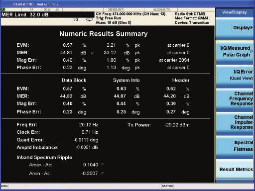
15 Figure 16. Modulation accuracy measurement with channel frequency response view Figure 17. Modulation accuracy measurement with channel impulse response view Figure 18. Modulation accuracy measurement with spectrum flatness view Figure 19. Modulation accuracy measurement with result metrics view 15

16 Demonstration 7: Monitor spectrum The monitor spectrum measurement is used as a quick, convenient means of looking at the entire spectrum. While it is similar to the spectrum analyzer mode, the functionality is greatly reduced for easy operation. The main purpose of the measurement is to show the spectrum. Instructions On the X-Series in DTMB (CTTB) mode: Activate monitor spectrum measurement [Meas] {Monitor Spectrum} Figure 20. Monitor spectrum measurement 16

 mode: Activate IQ waveform measurement (RF envelope default) View the I/Q waveform [Meas] {IQ Waveform} [View/Display] {I/Q Waveform} Figure 21.")
17 Demonstration 8: IQ waveform The waveform measurement is a generic measurement for viewing the input signal waveforms in the time domain. Under this measurement there is also an I/Q Waveform window, which shows the I and Q signal waveforms in parameters of voltage versus time to disclose the voltages, which comprise the complex modulated waveform of a digital signal. The waveform measurement can also be used to perform general purpose power measurements to a high degree of accuracy. Instructions On the X-Series in DTMB (CTTB) mode: Activate IQ waveform measurement (RF envelope default) View the I/Q waveform [Meas] {IQ Waveform} [View/Display] {I/Q Waveform} Figure 21. Waveform measurement with RF envelope view Figure 22. Waveform measurement with I/Q waveform view 17
 signal in single carrier mode with pilot insertion): Instructions On the Signal Studio")
18 Demonstration 9: Making DTMB (CTTB) signal measurement in single carrier mode The N6156A & W6156A measurement applications also support the measurement of single mode DTMB (CTTB) signals. Set up Signal Studio for Digital Video and PXA/MXA/ EXA/CXA as follows (this example shows the DTMB (CTTB) signal in single carrier mode with pilot insertion): Instructions On the Signal Studio software: Configure a test signal for demonstrations Click Carrier0 (DTMB Settings) under Waveform Setup on the left of the explorer menu Carrier0: Sub-Carrier Number = 1, Insert Pilot = True. For other parameters, use the default settings of reference spec Channel power The channel power measurement shows the spectrum of the signal. The two vpeak values on each side of the spectrum is the inserted dualpilot. The frequency distance between the two pilots should be equal to the symbol rate. Figure 23. Channel power measurement on a DTMB (CTTB) signal in single carrier mode 18
19 Modulation accuracy In single carrier mode, the insertion method of the dual-pilot is to add 1+j*0 to the odd symbol and add -1+j*0 to the even symbol, counted from the first symbol of a day frame. The constellation diagram is shown in Figure 24. Instructions On the X-Series in DTMB (CTTB) mode: Select demodulation options Activate modulation accuracy measurement (I/Q measured polar graph default, Figure 24) [Mode Setup] {Demod} {Carrier Format} {Single Carrier} {Pilot Insertion} {On} [Meas] {Mod Accuracy} Figure 24. Constellation diagram of a DTMB (CTTB) signal in single carrier mode Web Resources Product page: and X-Series signal analyzers: X-Series advanced measurement applications: Signal Studio software: Signal Studio software: Signal generators: 19
20 20 Keysight N6156A & W6156A DTMB (CTTB) Digital Video X-Series Measurement Application - Demo Guide mykeysight A personalized view into the information most relevant to you. Keysight Electronic Measurement Group DEKRA Certified ISO 9001:2008 Quality Management System Keysight Channel Partners Get the best of both worlds: Keysight s measurement expertise and product breadth, combined with channel partner convenience. For more information on Keysight Technologies products, applications or services, please contact your local Keysight office. The complete list is available at: Americas Canada (877) Brazil Mexico United States (800) Asia Paciic Australia China Hong Kong India Japan 0120 (421) 345 Korea Malaysia Singapore Taiwan Other AP Countries (65) Europe & Middle East Austria Belgium Finland France Germany Ireland Israel Italy Luxembourg Netherlands Russia Spain Sweden Switzerland Opt. 1 (DE) Opt. 2 (FR) Opt. 3 (IT) United Kingdom For other unlisted countries: (BP ) This information is subject to change without notice. Keysight Technologies, Published in USA, July 31, EN
Keysight Technologies N6152A & W6152A Digital Cable TV
 Keysight Technologies N6152A & W6152A Digital Cable TV X-Series Measurement Application Demo Guide Introduction This demonstration guide follows the list from page 2, which shows the demonstrations included
Keysight Technologies N6155A & W6155A ISDB-T with Tmm X-Series Measurement Application. Demo Guide
 Keysight Technologies N6155A & W6155A ISDB-T with Tmm X-Series Measurement Application Demo Guide ISDB-T with Tmm Digital Video Test Measurement Details This demonstration guide follows the list on this
Keysight Technologies N9063A & W9063A Analog Demodulation
 Keysight Technologies N9063A & W9063A Analog Demodulation X-Series Measurement Application Demo Guide FM is the most widely used analog demodulation scheme today, therefore this demonstration used uses
Keysight Technologies Phase Noise X-Series Measurement Application
 Keysight Technologies Phase Noise X-Series Measurement Application N9068C Technical Overview Phase noise measurements with log plot and spot frequency views Spectrum and IQ waveform monitoring for quick
Keysight Technologies N1918A Power Analysis Manager and U2000 Series USB Power Sensors. Demo Guide
 Keysight Technologies N1918A Power Analysis Manager and U2000 Series USB Power Sensors Demo Guide Introduction This demonstration guide helps you to get familiar with the basic setup and configuration
Keysight Technologies, Inc. UWB Antenna Measurements with the 20 GHz E5071C ENA Network Analyzer. Application Note
 Keysight Technologies, Inc. UWB Antenna Measurements with the 20 GHz E5071C ENA Network Analyzer Application Note Introduction Ultra-wideband (UWB) is a rapidly growing technology that is used to transmit
Keysight Technologies A Flexible Testbed to Evaluate Potential Co-Existence Issues Between Radar and Wireless
 Keysight Technologies A Flexible Testbed to Evaluate Potential Co-Existence Issues Between Radar and Wireless Application Note Photo courtesy US Department of Defense Problem: Radar and wireless may interfere
1xEV-DO X-Series Measurement Application N9076A & W9076A
 1xEV-DO X-Series Measurement Application N9076A & W9076A Technical Overview Perform 1xEV-DO forward and reverse link transmitter tests per 3GPP2 standards Support 1xEV-DO Rel. 0, Rev. A and Rev. B for
Keysight Technologies M9076A 1xEV-DO
 Keysight Technologies M9076A 1xEV-DO X-Series Measurement Application for PXI Vector Signal Analyzers Technical Overview Perform 1xEV-DO forward and reverse link transmitter tests per 3GPP2 standards Support
Keysight Technologies VMA Vector Modulation Analysis X-Series Measurement Application, Multi-Touch
 Keysight Technologies VMA Vector Modulation Analysis X-Series Measurement Application, Multi-Touch N9054C Technical Overview Perform standard-based and flexible digital demodulation analysis Multiple result
Keysight Technologies Noise Figure X-Series Measurement Application N9069A & W9069A
 Keysight Technologies Noise Figure X-Series Measurement Application N9069A & W9069A Technical Overview Characterize noise figure and gain of connectorized devices and system blocks with graphic, meter,
Keysight Technologies VSA Software for Simulation Environments BE/89601 BNE
 Keysight Technologies 89600 VSA Software for Simulation Environments 89601 BE/89601 BNE 89601BE and 89601BNE are no longer orderable after December 2017 because the bundled capability of simulation link
Keysight Technologies N6141A & W6141A EMI X-Series Measurement Application. Technical Overview
 Keysight Technologies N6141A & W6141A EMI X-Series Measurement Application Technical Overview EMI Measurement Application To avoid costly delays that can result from failed compliance testing, Keysight's
Introduction. Part 1. Introduction...2
 Keysight Technologies Simple Scalar Network Analysis of Frequency Converter Devices using the U2000 USB Power Sensor Series with the ENA Network Analyzer Application Note Introduction This application
Keysight Technologies Network Analyzer Measurements: Filter and Amplifier Examples. Application Note
 Keysight Technologies Network Analyzer Measurements: Filter and Amplifier Examples Application Note Introduction Both the magnitude and phase behavior of a component are critical to the performance of
Measurement Guide and Programming Examples
 Measurement Guide and Programming Examples N9073A-1FP W-CDMA Measurement Application N9073A-2FP HSDPA/HSUPA Measurement Application For use with the Agilent N9020A MXA and N9010A EXA Signal Analyzers Manufacturing
Introduction. Part 1. Introduction...2
 Keysight Technologies Simple Scalar Network Analysis of Frequency Converter Devices using the U2000 USB Power Sensor Series with the ENA Network Analyzer Application Note Introduction This application
Keysight DSOXT3FRA/DSOX4FRA/DSOX6FRA Frequency Response Analyzer (FRA) Option
 Option") Keysight DSOXT3FRA/DSOX4FRA/DSOX6FRA Frequency Response Analyzer (FRA) Option For Keysight 3000T, 4000A, and 6000A X-Series Oscilloscopes Data Sheet Introduction Frequency Response Analysis (FRA) is often
Keysight DSOXT3FRA/DSOX4FRA/DSOX6FRA Frequency Response Analyzer (FRA) Option For Keysight 3000T, 4000A, and 6000A X-Series Oscilloscopes Data Sheet Introduction Frequency Response Analysis (FRA) is often
cdma2000 X-Series Measurement Application N9072A & W9072A
 cdma2000 X-Series Measurement Application N9072A & W9072A Technical Overview Perform IS-95 or cdmaone and cdma2000 forward link and reverse link RF transmitter measurements per 3GPP2 specifications Perform
Keysight Technologies External Source Control X-Series Signal Analyzers Option ESC. Demo Guide
 Keysight Technologies External Source Control X-Series Signal Analyzers Option ESC Demo Guide External source control for X-Series signal analyzers (Option ESC) allows the Keysight PXA, MXA, EXA, and CXA
Keysight X-Series Signal Analyzers
 Keysight X-Series Signal Analyzers This manual provides documentation for the following models: PXA Signal Analyzer N9030A MXA Signal Analyzer N9020A EXA Signal Analyzer N9010A CXA Signal Analyzer N9000A
Keysight E5063A ENA Series Network Analyzer
 Keysight E5063A ENA Series Network Analyzer 100 khz to 500 M/1.5 G/3 G/4.5 G/6.5 G/8.5 G/14 G/18 GHz Configuration Guide 02 Keysight E5063A ENA Series Network Analyzer - Configuration Guide Ordering Guide
Keysight Technologies N7621B
 Keysight Technologies N7621B Signal Studio for Multitone Distortion Technical Overview Create Keysight Technologies, Inc. validated and performance optimized multitone and noise power ratio (NPR) signals
Keysight Technologies
 Keysight Technologies Easily Create Power Supply Output Sequences with Data Logging Application Brief 02 Keysight Easily Create Power Supply Output Sequences with Data Logging - Application Brief Why is
Keysight Technologies NFA Noise Figure Analyzer. Configuration Guide
 Keysight Technologies NFA Noise Figure Analyzer Configuration Guide Noise Figure Analyzer Overview Over 50 years of noise figure leadership Dedicated Noise Figure Analyzer Hard specifications to 26.5 GHz
Keysight Technologies 87405C 100 MHz to 18 GHz Preamplifier. Technical Overview
 Keysight Technologies 8745C 1 MHz to 18 GHz Preamplifier Technical Overview 2 Keysight 8745C 1 MHz to 18 GHz Preamplifier Technical Overview Introduction The Keysight Technologies, Inc. 8745C preamplifier
Keysight Technologies VOR and ILS Radio Navigation Receiver Test Using Option 302 for Keysight Signal Sources. Application Note
 Keysight Technologies VOR and ILS Radio Navigation Receiver Test Using Option 302 for Keysight Signal Sources Application Note Introduction The Keysight X-series (EXG and MXG) analog and vector signal
Keysight Technologies How to Measure 5 ns Rise/Fall Time on an RF Pulsed Power Amplifier Using the 8990B Peak Power Analyzer.
 Keysight Technologies How to Measure 5 ns Rise/Fall Time on an RF Pulsed Power Amplifier Using the 8990B Peak Power Analyzer Application Note Introduction RF IN RF OUT Waveform Generator Pulse Power Amplifier
Keysight Technologies N9398C/F/G and N9399C/F DC Block. Technical Overview
 Keysight Technologies N9398C/F/G and N9399C/F DC Block Technical Overview Introduction Key Features Maximize your operating range - 26.5, 50 or 67 GHz Improve calibration accuracy with exceptional return
Keysight Technologies ISDB-T/Tmm X-Series Measurement Application N6155A & W6155A. Technical Overview
 Keysight Technologies ISDB-T/Tmm X-Series Measurement Application N6155A & W6155A Technical Overview Introduction Measure ISDB-T or ISDB-Tmm RF transmitter, modulator, gap-filler, tuner, or amplifier performance
Keysight Technologies
 Keysight Technologies Easily Create Power Supply Output Sequences with Data Logging Application Brief 02 Keysight Easily Create Power Supply Output Sequences with Data Logging - Application Brief Why is
Keysight Technologies Analog Demodulation X-Series Measurement Application
 Keysight Technologies Analog Demodulation X-Series Measurement Application N9063C Technical Overview Perform one-button measurements for AM, FM, PM and FM stereo signals with multitouch user interface
Keysight Technologies RF & Microwave Attenuators. Performance you can count on
 Keysight Technologies RF & Microwave Attenuators Performance you can count on Key Features High reliability and exceptional repeatability reduce downtime Excellent RF specifications optimize test system
Keysight Technologies, Inc. Overcome PCB Loss and Deliver a Clean Eye to Your DUT Using Multi-tap De-emphasis
 Keysight Technologies, Inc. Overcome PCB Loss and Deliver a Clean Eye to Your DUT Using Multi-tap De-emphasis Application Brief Introduction Keysight Technologies, Inc. announces a new 32 Gb/s pattern
Keysight X-Series Signal Analyzers
 Keysight X-Series Signal Analyzers This manual provides documentation for the following Analyzers: PXA Signal Analyzer N9030A EXA Signal Analyzer N9010A MXA Signal Analyzer N9020A CXA Signal Analyzer N9000A
Keysight Technologies Achieving Accurate E-band Power Measurements with E8486A Waveguide Power Sensors. Application Note
 Keysight Technologies Achieving Accurate E-band Power Measurements with Waveguide Power Sensors Application Note Introduction The 60 to 90 GHz spectrum, or E-band, has been gaining more millimeter wave
Keysight Technologies Overcoming LTE-A RF Test Challenges. Application Note
 Keysight Technologies Overcoming LTE-A RF Test Challenges Application Note Introduction The LTE-A standard is being actively updated, bringing new definitions and challenges to RF engineers configuring
Keysight Technologies N9310A RF Signal Generator
 Keysight Technologies N9310A RF Signal Generator 02 Keysight N9310A RF Signal Generator Brochure All the capability and reliability of a Keysight instrument you need at a price you ve always wanted Reliable
Keysight Technologies 7 Hints That Every Engineer Should Know When Making Power Measurements with Oscilloscopes. Application Note
 Keysight Technologies 7 Hints That Every Engineer Should Know When Making Power Measurements with Oscilloscopes Application Note Seven Hints for Making Power Measurements with Oscilloscopes Achieving maximized
N9051A Pulse Measurement Software
 N9051A Pulse Measurement Software X-Series Signal Analyzers and PSA Series Spectrum Analyzers Technical Overview Characterize pulse performance using a wide range of parameters including pulse width, rise/fall
Keysight Technologies Understanding the SystemVue To ADS Simulation Bridge. Application Note
 Keysight Technologies Understanding the To Simulation Bridge Application Note Introduction The Keysight Technologies, Inc. is a new system-level design environment that enables a top-down, model-based
Keysight Technologies RS-232/UART Protocol Triggering and Decode for Infiniium 9000A and 9000 H-Series Oscilloscopes. Data Sheet
 Keysight Technologies RS-232/UART Protocol Triggering and Decode for Infiniium 9000A and 9000 H-Series Oscilloscopes Data Sheet This application is available in the following license variations. Order
Keysight Technologies N4983A Multiplexer and Demultiplexer. Data Sheet
 Keysight Technologies N4983A Multiplexer and Demultiplexer Data Sheet 02 Keysight N4983A Multiplexer and Demultiplexer - Data Sheet N4983A-M40 44 Gb/s multiplexer Features Wide operating range, 2 to 44
Keysight E5063A ENA Vector Network Analyzer
 Keysight E5063A ENA Vector Network Analyzer 100 khz to 500 M/1.5 G/3 G/4.5 G/6.5 G/8.5 G/14 G/18 GHz Configuration Guide 02 Keysight E5063A ENA Vector Network Analyzer - Configuration Guide Ordering Guide
Keysight Technologies Pulse Analysis X-Series Measurement App, Multi-Touch
 Keysight Technologies Pulse Analysis X-Series Measurement App, Multi-Touch N9067C Technical Overview Automatically synchronize to pulse modulated signals for radar and electronic warfare (EW) applications
Keysight Technologies Automated Receiver Sensitivity Measurements Using U8903B. Application Note
 Keysight Technologies Automated Receiver Sensitivity Measurements Using U8903B Application Note Introduction Sensitivity is a key specification for any radio receiver and is characterized by the minimum
Keysight Technologies 87405C 100 MHz to 18 GHz Preamplifier. Technical Overview
 Keysight Technologies 8745C 1 MHz to 18 GHz Preamplifier Technical Overview 2 Keysight 8745C 1 MHz to 18 GHz Preamplifier Technical Overview Introduction The Keysight Technologies, Inc. 8745C preamplifier
Keysight N9310A RF Signal Generator
 Keysight N9310A RF Signal Generator 9 khz to 3.0 GHz Data Sheet 02 Keysight N9310A RF Signal Generator - Data Sheet Definitions and Conditions Specifications describe the performance of parameters that
Keysight HMMC-1002 DC 50 GHz Variable Attenuator
 Keysight HMMC-1002 DC 50 GHz Variable Attenuator 1GG7-8001 Data Sheet Features Specified frequency range: DC to 26.5 GHz Return loss: 10 db Minimum attenuation: 2.0 db Maximum attenuation: 30.0 db 02 Keysight
Keysight Technologies Optimizing RF and Microwave Spectrum Analyzer Dynamic Range. Application Note
 Keysight Technologies Optimizing RF and Microwave Spectrum Analyzer Dynamic Range Application Note 02 Keysight Optimizing RF and Microwave Spectrum Analyzer Dynamic Range Application Note 1. Introduction
Keysight Technologies N9398C/F/G and N9399C/F DC Block. Technical Overview
 Keysight Technologies N9398C/F/G and N9399C/F DC Block Technical Overview Introduction Key Features Maximize your operating range - 26.5, 50 or 67 GHz Improve calibration accuracy with exceptional return
Keysight Technologies MATLAB Data Analysis Software Packages
 Keysight Technologies MATLAB Data Analysis Software Packages For Keysight Oscilloscopes Data Sheet 02 Keysight MATLAB Data Analysis Software Packages - Data Sheet Enhance your InfiniiVision or Infiniium
Keysight N8836A PAM-4 Measurement Application For Infiniium S-Series, 90000A, V-Series, X-Series, Q-Series, and Z-Series Oscilloscopes
 Keysight N8836A PAM-4 Measurement Application For S-Series, 90000A, V-Series, 90000 X-Series, 90000 Q-Series, and Z-Series Oscilloscopes Characterize electrical pulse amplitude modulated (PAM) signals
Keysight Technologies WLAN a/b/g/j/p/n/ac/af/ah/ax X-Series Measurement Application N9077A & W9077A
 Keysight Technologies WLAN 802.11a/b/g/j/p/n/ac/af/ah/ax X-Series Measurement Application N9077A & W9077A Technical Overview Perform WLAN spectrum and modulation measurements based on IEEE 802.11a/b/g/j/p/n/ac/af/ah
Keysight Technologies 8490G Coaxial Attenuators. Technical Overview
 Keysight Technologies 8490G Coaxial Attenuators Technical Overview Introduction Key Specifications Maximize your operating frequency range for DC to 67 GHz application Minimize your measurement uncertainty
Keysight Technologies Migrating from the 4268A/4288A Capacitance Meter to the E4981A Capacitance Meter. Technical Overview
 Keysight Technologies Migrating from the 4268A/4288A Capacitance Meter to the E4981A Capacitance Meter Technical Overview E4981A Capacitance Meter The E4981A capacitance meter provides the best combination
Keysight N9311X RF and Microwave Accessory Kit for Low-cost Handheld and Benchtop Solutions. Technical Overview
 Keysight N9311X RF and Microwave Accessory Kit for Low-cost Handheld and Benchtop Solutions Technical Overview 02 Keysight N9311X RF and Microwave Accessory Kit for Low-cost Handheld and Benchtop Solutions
Keysight Technologies A comparison of Keysight Network Analyzers for Applications < 3 GHz. Selection Guide
 Keysight Technologies A comparison of Keysight Network Analyzers for Applications < 3 GHz Selection Guide N9923A FieldFox RF Vector Network Analyzer, 2 MHz to 4/6 GHz Keysight Technologies, Inc. handheld
Keysight Technologies Essential Capabilities of EMI Receivers. Application Note
 Keysight Technologies Essential Capabilities of EMI Receivers Application Note Contents Introduction... 3 CISPR 16-1-1 Compliance... 3 MIL-STD-461 Compliance... 4 Important features not required by CISPR
Keysight Technologies N4985A System Amplifiers
 Keysight Technologies N4985A System Amplifiers Data Sheet N4985A-P15 10 MHz to 50 GHz N4985A-P25 2 to 50 GHz N4985A-S30 100 khz to 30 GHz N4985A-S50 100 khz to 50 GHz Exceptional gain and power performance
Keysight Technologies Enhancing Measurement Performance for the Testing of Wideband MIMO Signals
 Keysight Technologies Enhancing Measurement Performance for the Testing of Wideband MIMO Signals White Paper How to generate and apply magnitude and phase corrections for multichannel baseband IQ measurements
Keysight Technologies Measuring Group Delay of Frequency Converters with Embedded Local Oscillators. Application Note
 Keysight Technologies Measuring Group Delay of Frequency Converters with Embedded Local Oscillators Application Note Introduction Mixers and frequency converters lie at the heart of wireless and satellite
X-Series Measurement Application N9077C
 Keysight Technologies WLAN 802.11a/b/g/j/p/n/ac/af/ah/ax X-Series Measurement Application N9077C Technical Overview Perform WLAN spectrum and modulation measurements based on IEEE 802.11a/b/g/j/p/n/ac/af/ah/ax
Keysight Technologies High Frequency Probing Solutions for Time and Frequency Domain Applications. Application Note
 Keysight Technologies High Frequency Probing Solutions for Time and Frequency Domain Applications Application Note Introduction Increasing consumer and business demand for cellular, wireless connectivity,
Keysight Technologies Making Current-Voltage Measurement Using SMU
 Keysight Technologies Making Current-Voltage Measurement Using SMU Keysight B2901A/02A/11A/12A Precision Source/Measure Unit Demonstration Guide Introduction The Keysight Technologies, Inc. B2901A/02A/11A/12A
Keysight Technologies Using an External Trigger to Generate Pulses with the B2960A
 Keysight Technologies Using an External Trigger to Generate Pulses with the B2960A B2960A 6.5 Digit Low Noise Power Source Demo Guide 02 Keysight Using an External Trigger to Generate Pulses with the B2960A
Keysight Technologies N9071A GSM/EDGE/EDGE Evolution W9071A GSM/EDGE
 Keysight Technologies N9071A GSM/EDGE/EDGE Evolution W9071A GSM/EDGE X-Series Measurement Application Demo Guide Introduction The GSM/EDGE/EDGE Evolution measurement application transforms the X-Series
Keysight Technologies Differences in Application Between Power Dividers and Power Splitters. Application Note
 Keysight Technologies Differences in Application Between Dividers and Splitters Application Note 02 Keysight Differences in Application Between Dividers and Splitters Application Note Introduction dividers
Keysight X-Series Signal Analyzers
 Keysight X-Series Signal Analyzers This manual provides documentation for the following Analyzers: PXA Signal Analyzer N9030A EXA Signal Analyzer N9010A MXA Signal Analyzer N9020A Notice: This document
Keysight M9485A PXIe Multiport Vector Network Analyzer
 Keysight M9485A PXIe Multiport Vector Network Analyzer 02 Keysight M9485A PXIe Multiport Vector Network Analyzer - Brochure High-Performance PXI Multiport Vector Network Analyzer (VNA) Innovative solution
Keysight Technologies Compatibility of USB Power Sensors with Keysight Instruments. Application Note
 Keysight Technologies Compatibility of USB Power Sensors with Keysight Instruments Application Note Table of Contents Keysight USB Power Sensors 2 USB Power Sensor s Compatibility 3 with Keysight Instruments
Keysight Technologies DSOX3PWR/DSOX4PWR/DSOX6PWR Power Measurement Options
 Keysight Technologies DSOX3PWR/DSOX4PWR/DSOX6PWR Power Measurement Options Data Sheet For InfiniiVision 3000, 4000 and 6000 X-Series Oscilloscopes Achieve cost-effective analysis of your switching mode
Keysight U1882B Measurement Application for Infiniium Oscilloscopes. Data Sheet
 Keysight U1882B Measurement Application for Infiniium Oscilloscopes Data Sheet 02 Keysight U1882B Measurement Application for Infiniium Oscilloscopes - Data Sheet Fast, Automatic and Reliable Characterization
Keysight Technologies P9400A/C Solid State PIN Diode Transfer Switches
 Keysight Technologies P9400A/C Solid State PIN Diode Transfer Switches P9400A 100 MHz to 8 GHz PIN transfer switch P9400C 100 MHz to 18 GHz PIN transfer switch Technical Overview Key Features Minimize
Keysight Technologies USB Preamplifiers
 Keysight Technologies USB Preamplifiers U77/A 1 MHz to 4 GHz U77/C 1 MHz to 6. GHz U77/F to GHz Technical Overview Keysight USB Preamplifiers U77A/C/F - Technical Overview Key Features and Benefits Automatic
Keysight Redefines 50 GHz Portability. Get a $30k Credit When You Move Up to FieldFox
 Keysight Redefines 50 GHz Portability Get a $30k Credit When You Move Up to FieldFox 02 Keysight Keysight Redefines 50 GHz Portability - Brochure For over 20 years, the 8565 has been the only 50 GHz portable
Keysight Technologies FFT and Pulsed RF Measurements with 3000T X-Series Oscilloscopes. Application Note
 Keysight Technologies FFT and Pulsed RF Measurements with 3000T X-Series Oscilloscopes Application Note Introduction The oscilloscope Fast Fourier Transform (FFT) function and a variety of other math functions
Keysight Technologies Isolating Problems and Optimizing Wireless Designs with Digital Demodulation and EVM
 Keysight Technologies Isolating Problems and Optimizing Wireless Designs with Digital Demodulation and EVM Key Considerations for Troubleshooting Digital Modulation and Going Beyond Pass/Fail Testing Application
Keysight LTE and LTE-Advanced FDD/TDD X-Series Measurement Application
 Keysight LTE and LTE-Advanced FDD/TDD X-Series Measurement Application N9080B and W9080B N9082B and W9082B Technical Overview Perform LTE plus LTE-Advanced FDD and TDD base station (enb) and user equipment
Keysight Technologies Secondary Radar Transponder Testing Using the 8990B Peak Power Analyzer. Application Note
 Keysight Technologies Secondary Radar Transponder Testing Using the 8990B Peak Power Analyzer Application Note Introduction After a brief review of radar systems and the role of transponders, this application
Keysight Technologies Signal Studio for DFS Radar Profiles N7607C
 Keysight Technologies Signal Studio for DFS Radar Profiles N7607C Technical Overview Create Keysight validated and performance optimized dynamic frequency selection radar profiles Enable creation of FCC,
Keysight M940xA PXIe Optical Extenders for Instrumentation. Data Sheet
 Keysight M940xA PXIe Optical Extenders for Instrumentation Data Sheet Overview Introduction The Keysight Technologies, Inc. Optical Extenders for Instruments can transmit your RF or Microwave signal without
Keysight Technologies W-CDMA/HSPA+ X-Series Measurement Application N9073A & W9073A
 Keysight Technologies W-CDMA/HSPA+ X-Series Measurement Application N9073A & W9073A Technical Overview Perform W-CDMA, HSPA, and HSPA+ downlink and uplink transmitter test per 3GPP standard Perform one-button
Keysight Technologies Accurate Evaluation of MEMS Piezoelectric Sensors and Actuators Using the E4990A Impedance Analyzer.
 Keysight Technologies Accurate Evaluation of MEMS Piezoelectric Sensors and Actuators Using the E4990A Impedance Analyzer Application Note Introduction Excellent impedance measurement accuracy and repeatability
Keysight Technologies Measuring Low Current Consumption with a Digital Multimeter
 Keysight Technologies Measuring Low Current Consumption with a Digital Multimeter Application Brief Test Challenges: Characterizing the power consumption of a battery powered device Testing the current
Keysight Technologies How to Read Your Power Supply s Data Sheet. Application Note
 Keysight Technologies How to Read Your Power Supply s Data Sheet Application Note Introduction If you are designing electronic devices and you need to power up a design for the first time, there s a good
Keysight Technologies Z9070B Wideband Signal Analysis Solution. Technical Overview
 Keysight Technologies Z9070B Wideband Signal Analysis Solution Technical Overview 02 Keysight Z9070B Wideband Signal Analysis Solution - Technical Overview Introduction Wideband commercial, satellite or
Keysight Technologies N6850A Broadband Omnidirectional Antenna. Data Sheet
 Keysight Technologies N6850A Broadband Omnidirectional Antenna Data Sheet 02 Keysight N6850A Broadband Omnidirectional Antenna - Data Sheet Industries and Applications Spectrum monitoring and signal location,
Keysight Technologies Compatibility of USB Power Sensors with Keysight Instruments. Application Note
 Keysight Technologies Compatibility of USB Power Sensors with Keysight Instruments Application Note 02 Keysight Compatibility of USB Power Sensors with Keysight Instruments Application Note Table of Contents
Keysight Technologies N2792A/N2818A 200 MHz and N2793A/N2819A 800 MHz Differential Probes. Data Sheet
 Keysight Technologies N2792A/N2818A 200 MHz and N2793A/N2819A 800 MHz Differential Probes Data Sheet Introduction The Keysight Technologies, Inc. N2792A/93A and N2818A/19A differential probes provide the
Keysight Technologies DVB-T/H with T2 X-Series Measurement Application N6153A & W6153A. Technical Overview
 Keysight Technologies DVB-T/H with T2 X-Series Measurement Application N6153A & W6153A Technical Overview Introduction DVB-T/H/T2 RF transmitters, modulators, gap-fillers, tuners, or amplifiers measurements
Keysight Technologies Accurate NBTI Characterization Using Timing-on-the-fly Sampling Mode. Application Note
 Keysight Technologies Accurate NBTI Characterization Using Timing-on-the-fly Sampling Mode Application Note Introduction Keysight B1500A Semiconductor Device Analyzer Controlled dynamic recovery with 100
Keysight Technologies 1 mw 50 MHz Power Reference Measurement with the N432A Thermistor Power Meter. Application Note
 Keysight Technologies 1 mw 50 MHz Power Reference Measurement with the N432A Thermistor Power Meter Application Note Introduction This application note explains the application procedure for using the
Keysight Technologies DVB-T/H with T2 X-Series Measurement Application N6153A & W6153A. Technical Overview
 Keysight Technologies DVB-T/H with T2 X-Series Measurement Application N6153A & W6153A Technical Overview Introduction DVB-T/H/T2 RF transmitters, modulators, gap-fillers, tuners, or amplifiers measurements
Keysight Technologies How to Take Fast, Simultaneous Measurements of Two or More Signals Using BenchVue Software. Application Note
 Keysight Technologies How to Take Fast, Simultaneous Measurements of Two or More Signals Using BenchVue Software Application Note 02 Keysight How to Take Fast, Simultaneous Measurements of Two or More
Keysight Technologies Electronic Calibration (ECal) Modules for Vector Network Analyzers
 Modules for Vector Network Analyzers") Keysight Technologies Electronic Calibration (ECal) Modules for Vector Network Analyzers N4690 Series, 2-port Microwave ECal 85090 Series, 2-port RF ECal N4430 Series, 4-port ECal N7550 Series, 2-port
Keysight Technologies Electronic Calibration (ECal) Modules for Vector Network Analyzers N4690 Series, 2-port Microwave ECal 85090 Series, 2-port RF ECal N4430 Series, 4-port ECal N7550 Series, 2-port
Keysight Technologies Making Field Effect Transistor Characterization Using SMU
 Keysight Technologies Making Field Effect Transistor Characterization Using SMU B2900A Precision Source/Measure Unit Demo Guide Introduction The Keysight s B2900A Series Precision Source/Measure Unit (SMU)
Keysight Technologies Signal Studio for cdma2000/1xev-do N7601B
 Keysight Technologies Signal Studio for cdma2000/1xev-do N7601B Technical Overview Create Keysight validated and performance optimized reference signals compliant to IS- 95A, cdma2000 and 1xEV-DO Rev.
Keysight Technologies LTE Base Station (enb) Transmitter and Component Test
 Transmitter and Component Test") Keysight Technologies LTE Base Station (enb) Transmitter and Component Test Demo Guide Using Signal Studio software and X-Series signal analyzer measurement applications for LTE Featured Products: N7624B
Keysight Technologies LTE Base Station (enb) Transmitter and Component Test Demo Guide Using Signal Studio software and X-Series signal analyzer measurement applications for LTE Featured Products: N7624B
Keysight LTE FDD/TDD X-Series Measurement Application N9080A and W9080A N9082A and W9082A
 Keysight LTE FDD/TDD X-Series Measurement Application N9080A and W9080A N9082A and W9082A Technical Overview Note: N9080A and N9082A have been replaced by N9080B and N9082B, respectively. Please refer