MGL Avionics. Razor 3.1/8 control head for V16 aviation band transceiver and N16 VHF navigation receiver
|
|
|
- Georgina Benson
- 6 years ago
- Views:
Transcription
1 MGL Avionics Razor 3.1/8 control head for V16 aviation band transceiver and N16 VHF navigation receiver User and Installation manual Page 1
2 Table of Contents Note...4 General...4 Document history...4 Description...4 Multiple control heads...4 Interface with MGL EFIS systems...5 Interface with non-mgl EFIS systems...5 Multiple V16/N16 systems...5 V16 COM radio interface operation...6 Rotary control...6 Touch screen...6 Ambient light sensor...6 Main display - receive...7 Main display - transmit...8 Messages...9 STUCK PTT!!!...9 V16 FAULT...9 Antenna!...9 Adjusting volumes and squelch...11 Entering a new standby frequency...13 Using the numeric keypad...13 Using the rotary control...13 Using the channel list...15 Frequency lists downloaded from external devices...16 COM lists...16 NAV lists...17 N16 navigation radio interface operation...19 Typical navigation displays...20 Adjusting the OBS...21 NAV control...22 Adjusting RX volume...22 Adjusting the squelch...23 Localizer backcourse...23 The NAVCOM mode...23 The audio output...24 The morse station decoder...24 Channel identification by text...25 The Menu...26 COM Setup Menu...27 Head Setup Menu...27 No TX Info/Show TX info...28 VHF...28 Edit channels...28 Set Backlight...28 Page 2
3 EMU K Channels/25K Channels...29 Inputs...29 About...29 Rotary rollover/clamp...30 Check...30 Razor head firmware...30 Editing channel memory...31 Editing a channel...32 Remote channel lists...33 Environmental qualification matrix...34 Typical connection diagrams...36 Remote control...37 Pinout for 3.18 Razor and 2.25 Vega transceiver control head...38 Specifications...39 Dimensions...40 Garmin protocol limitations...42 Example Harness schematic...43 NAVCOM device using V16 and N Using audio transformer on the AUX input...45 Page 3
4 Note This document details operation of the Razor NAV/COM control head for COM, NAV and NAVCOM operations. This document is valid for Razor firmware Razor devices prior to this can be updated to this version via RS232 using a freely downloadable application from the MGL Avionics website. Versions prior tho this only support COM operation. General This manual documents the installation and use of the MGL Avionics Razor NAV/COM 3.1/8 control head. The Razor NAV/COM control head is designed to interface to a MGL Avionics V16 VHF airband transceiver and/or a MGL Avionics N16 VHF Navigation receiver. Document history 21 February 2018 Added NAV and NAVCOM functionality 14 November 2017, first release. Description The Razor control head consists of a body designed to fit a standard 3.1/8 instrument cutout. The Razor is designed for panel front mounting. The Razor features a 3.2 portrait mode color TFT touch screen with a wide viewing angle. A Rotary control is provided. Display light intensity may be adjusted to fixed values or set automatically based on ambient light levels. The Razor interfaces to a V16 and or N16 using a two wire CAN bus. Two RS232 ports are provided. RS232 port 1 may be used as interface to third party systems implementing industry standard communication protocols. The same port may also be used to upload firmware updates to the Razor using a PC application provided by MGL Avionics. RS232 port 2 is reserved for special applications and is not currently used. Two analog voltage inputs are provided. Input one may be used together with a switch to implement a stick mounted last reception recall for the V16 transceiver. Input two may be used to implement a selection of one, two or three button frequency or channel selection switches. Multiple control heads There are no limitations to the number of control heads installed in parallel. Control head types can be mixed, for example you may mix Razor 3.1/8 heads with Vega Page 4
5 you2.14 heads. Heads require no specific configuration for multiple head operation. Simply connect them in parallel on the CAN bus. Interface with MGL EFIS systems Heads are not connected in any way to a MGL Avionics EFIS system. Should you wish to operate an MGL EFIS with a V16 and/or N16, the MGL EFIS connects directly to the V16 via an EFIS RS232 port. In case of a V16 and N16 combination, the N16 is connected to the V16 via CAN bus and the V16 RS232 port provides both V16 and N16 data to the EFIS. In case of a single N16 receiver, connect the RS232 port 1 of the N16 to the RS232 port of the EFIS. Note that the CAN bus between heads, V16 and N16 is a private CAN bus. It must not be connected to an EFIS CAN bus or any other can bus in your aircraft. You may operate heads and EFIS connection at the same time. Interface with non-mgl EFIS systems Using any Razor or Vega head, RS232 port 1 implements a industry standard, Garmin compatible protocol. As there are several protocol types please select the desired variant in the head setup menu. Note: If you have both V16 and N16 connected via CAN bus to your head, you can select a NAV/COM protocol such as SL30 or GNC255. If you have only a V16 connected, select one of the COM protocols such as SL40, GTR200, GTR225. It is possible to connect only a N16. In this case select a NAV/COM protocol. The protocol will include the COM parts but these will not be functional for example if you were to set a COM frequency this will not work and the head will return a fixed frequency set to Mhz. The protocols are implemented fully including various forms of frequency lists and tables depending on the chosen protocol which can be used with compatible GPS receivers. Note: Generally, EFIS systems do not download frequency lists but set individual frequencies from their databases. Multiple V16/N16 systems Should you wish to use multiple V16 and/or N16 systems, please wire each system with a separate CAN bus. Page 5
6 V16 COM radio interface operation Touch screen Rotary control with push down button Ambient light sensor Rotary control This is used to enter a new standby frequency, flip active and standby frequency, switch scanning on and off and select the 121.5Mhz emergency channel. The Rotary control is also used to select from preset channel lists and can be used for many of the menu and setup functions. It is also used to set volume and squelch levels. Touch screen The touch screen duplicates many of the rotary control functions and is also extensively used with the menu system. Ambient light sensor The display brightness can be adjusted either in fixed steps (using the menu) or it can be set to automatically adjust depending on the amount of ambient light measured at the sensor. Page 6
7 Main display - receive The active Frequency Touch here to Flip active and Standby frequencies Touch here To set volume or Squelch levels Text related to frequency From channel storage Current receive Signal level in dbm Standby frequency, Monitored if scanning Active. Touch here to enter New standby frequency Using numeric keypad Touch here to playback Last received message(s) Touch here To switch scanning On and off. Touch here To select standby Frequency from Channel storage Touch here to Setup Transceiver and head Notes: Frequency display flashes when signal received above squelch level. Signal strength readout in dbm only visible when signal above squelch level. Internal channel storage can be edited via the Menu -> head setup. Further channel storage options available via downloaded channel lists from external equipment depending on protocols selected and availability of such functionality on external equipment such as EFIS systems. Touching playback plays back last received message. If pressed again while message is playing back - advances to next older message. If playback allowed to finish, next playback Page 7

8 requests starts from latest message again. Playback may also be activated via a remote switch. Channel based frequency selection may be operated via remote switches. This can be configured to operate in various modes and number of switches. Main display - transmit Active frequency Currently transmitting Current modulation Of TX carrier. Visual Check of actual TX signal. Current Average transmit Power (carrier Power) expressed In Watts Current antenna match Expressed as Voltage standing wave Ratio (VSWR) Notes: TX power and VSWR are only shown during TX if "Show TX Info" is selected in Menu -> Head. If not selected, the standby frequency will be shown in this field. Current modulation is derived from actual demodulation of the outgoing TX carrier wave and is a true reflection of modulation of the carrier. Transmit power is a true RF forward power measurement using a directional coupler at the antenna connector. Typical readings are around 10W (or 5W if low power TX mode selected). Power readings can vary depending on tuned frequency, antenna match at that frequency, internal temperature of the transmitter (if exceeding high levels) or power supply voltage if below 13.8V DC during transmit. VSWR reading is taken from a directional coupler at the antenna connector which looks into the transmitter harmonics filter as termination. Due to variable impedance at this location the VSWR reading may differ slightly from that of a similar meter inserted at the antenna but nevertheless is a good indication of antenna match. A good antenna match would give readings below 1.5 at any frequency. Readings above 2.0 should be investigated and may indicate a badly tuned or unsuitable antenna. Transmitting into a 50 ohm RF dummy load produces a perfect match and a reading of 1.0. Page 8

9 Messages Messages requiring alerts alternate with the standby frequency field. The following messages may be displayed: STUCK PTT!!! This displays when transmission has been active for 35 seconds. The V16 conforms to the requirements of DO-207. After 35 seconds the V16 reverts back to receive mode even if the PTT remains active. Releasing PTT resets the 35 second timer and a new transmission may commence. V16 FAULT This displays if the internal self diagnostics of the V16 transceiver has detected an internal fault that may cause incorrect operation. Please make arrangements to have your V16 transceiver checked and if required, repaired by a qualified service lab. Antenna! This message will be displayed in case of a very bad antenna match during transmit. If this message appears transmit power will have been reduced automatically to prevent destruction of the transmitter. Please check your antenna and antenna cable as well as connectors for shorts or open circuits. If this happens with an antenna that was previously operating fine, check connectivity to the antenna ground plane and check for corrosion. Page 9
10 For new installations, please ensure that your antenna has a properly configured ground plane of sufficient size. Page 10
11 Adjusting volumes and squelch The V16 features independent receive and intercom volume controls plus a semi-automatic receiver squelch. To adjust any of these settings, touch the field showing the current values: This results in: Tap to alternate between the three settings. While the setting is shown using a large bargraph, use the rotary control to adjust the setting. Notes: Typical volume settings for aviation headsets (2 x 600 ohms impedance) tends to be in the region of 60-70%. If the V16 is connected to an intercom system you may prefer much lower levels to avoid over driving the intercom inputs. Receiver squelch is adjusted in steps of about 1 dbm from just under -100 to -70. Typical settings tend to be in the range of -95dbm. You should adjust to a setting that just cancels the receiver noise if there is no reception of a sufficiently strong signal. Avoid too high squelch settings this will make your receiver insensitive to weak signals, unless this is your intention. Be aware that higher than normal squelch settings may indicate interference from on-board electrical systems typically these would be frequency dependent. Good and proper installation of your V16 can help to minimize such effects. Pay particular attention to a good antenna match using the on-board VSWR meter and also of the location of antenna cable and antenna itself with respect to on-board interferers. Distance minimizes interference! The V16 squelch is on the semi-automatic type. This combines the positive elements of a fully automatic squelch with the control of a manual squelch. When you adjust the squelch or when the V16 powers up squelch is set to your set level. However, the V16 is allowed to adjust starting at this value for a small amount depending on the received signal so it can track the Page 11
12 noise floor which typically changes a bit with location and frequency. Page 12

13 Entering a new standby frequency Using the numeric keypad Touch the standby frequency to activate the numeric keypad. Entry starts with the 10's of MHZ (you do not need to type the 100's of MHZ). A blinking cursor shows the digit you are changing. Only valid numerics for a given position may be entered. For example, the 10's of MHZ will only accept the numbers "1", "2" or "3". Use "BS" to move to the last digit entered if you made a mistake. Use "X" to abandon any entry and return to the normal display without changing the standby frequency. To complete the entry, either enter all of the digits or touch the frequency display area when you are done. Notes: Using the numeric keypad allows you to enter 8.33Khz and 25Khz channels regardless of the channel spacing setup in the head setup menu. Using the rotary control "Click" means push the rotary control towards the panel without turning it - you will notice a distinct "click" action. To enter a new standby frequency - rotate the knob. You will notice the MHZ part of the frequency highlighted and the numbers changing with your rotations, Clockwise to increase, anti-clockwise to decrease. Page 13
14 When satisfied with your selection and you would like to change the Khz, "Click" the knob. Change the 100's of KHZ by rotating the knob. When satisfied, "Click" the knob. Now change the 10's and 1's of the Khz portion by rotating the knob. "Click" when done - you return to the normal display with the new standby frequency. Notes: Using the rotary knob you can restrict entry to only use 25Khz channels by selecting "25Khz" channel spacing in the head setup menu. Using the rotary control to enter only partial frequencies - for example just the MHZ (and leave the KHZ unchanged) - change the MHZ as needed and "click" twice or simply leave the display as is - it will automatically time out after a few seconds and accept the new frequency. "Click" the knob without first turning it will flip main and standby frequencies. This means to rapidly enter a new standby frequency and flip it into active, enter the new frequency and then simply "click" once more. Note: The behavior of the khz selection using the rotary control is dependent on the Rotary rollover or Rotary clamp selection in the head setup menu. Page 14

15 Using the channel list Touch the "CH" button on the display. which results in: The highlighted Field will be selected If you click the Rotary controi Touch or drag The slider with your Finger to rapidly Move though the list The highlighted field Moves if you Rotate the rotary control You may define Up to 100 channels Touch here to Exit without Selecting a New frequency Channels not yet Defined show as 118,000Mhz with No text added Note: you can also drag the channel list using your finger and select a frequency by touching a frequency entry. You can edit the contents of the channel list in the Menu -> Head -> Edit channels. Page 15
.")
16 Frequency lists downloaded from external devices COM lists If at least one frequency list downloaded from an external source is available then your channel selection button is bracketed <CH>. Tapping the CH button will bring up a list selection display: Each external list is identified by an airport ID (as downloaded from the external device). Select the desired list or choose the internal list. You can then proceed to choose an entry from that list. A selected frequency will be inserted into your standby frequency. Page 16

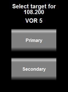
17 NAV lists If your Razor is selected as a NAV head then you will be given the choice of either a VOR or ILS (or both) list provided either of these has been downloaded from an external device. After you choose a frequency from either list or the internal list you will be asked if you would like to select that frequency to the primary or secondary NAV frequency. Once you have chosen channel from the chosen list you will be asked to indicate the target for the new frequency. Choose primary or secondary. Note: This choice applies only to NAV frequencies. COM frequencies are always sent to the COM standby channel. Page 17
18 Page 18
. Press for 4 seconds or longer to send the 121.")
19 N16 navigation radio interface operation Tap here to set the primary frequency Rotate the rotary control to set the OBS radial. Press the rotary control briefly to swap primary and secondary frequencies. Press and hold for two seconds to change the SCAN state (ON or OFF). Press for 4 seconds or longer to send the 121.5Mhz emergency frequency to a connected COM radio. Tap here to set the secondary frequency Tap here to enter the menu system Tap here to enable yhe secondary frequency (SCAN ON) Select from internal channel database or downloaded VOR or ILS frequency lists Tap anywhere on a VOR section of the display (except the frequency) to change to the VOR control menu which allows you to set the RX volume, RX squelch as well as Audio and ID enables. Tap anywhere on a ILS section of the display (except the frequency) to change to the ILS control menu which allows you to set the RX volume, RX squelch as well as Audio and ID enables. It also allows you to change to localizer backcourse navigation which is indicated by the letters BC on the needles display. Page 19
. During RX, signal strengths are shown. Any fault or attention messages will flash in red in this section.")

20 Typical navigation displays NAVCOM display. In this mode the COM is shown at the top section of the dispay and the NAV section occupies the bottom section. We see the active and standby COM frequencies and any descriptors (if available). During RX, signal strengths are shown. Any fault or attention messages will flash in red in this section. The NAV section shows the primary frequency tuned to an ILS localizer frequency. The paired glide slope is flagged and receiving a signal at -92dbm while the localizer is unflagged at a signal level of -77dbm. The needles show we are on glide slope and tracking the localizer. The secondary NAV frequency is tuned to a VOR station and is receiving at -81dbm. The station is unflagged and we are showing a radial of 000 degrees. Since this is a VOR on the secondary channel there is no CDI and the radial shown is the FROM radial. Tapping the COM section of the display changes the display to COM mode. This allows you control the COM device. Similar, tapping the NAV section of the display changes the display to NAV mode. This allows you control the NAV device. If no activity is detected for 6 seconds the Razor reverts back to the NAVCOM display. While the NAVCOM display is showing the rotary control can be used to adjust the OBS bearing if the primary NAV frequency is tuned to a VOR station. NAV display. Primary frequency is tuned to an ILS localizer and we are receiving at -77dbm. The localizer is unflagged. We are below the glide slope and to the left of the runway centerline. The GS is being received at -92dbm and is flagged and should be used with caution. The secondary frequency is tuned to a VOR station that is receiving at -81dbm. We are on the FROM radial 000 degrees. As this is a secondary frequency there is no VOR CDI and we are shown the radial only. This is used for radial crossing navigation. SCAN, CH and Menu buttons work as described in the COM section of this manual. Page 20


21 Note the CH is bracketed: <CH>. This means externally downloaded VOR and/or ILS frequency lists are available. If there are no brackets, it means you can only select from the internal frequency list. To change either primary or secondary frequencies, simply tap on the frequency. NAV display. Primary frequency is tuned to a VOR station and receiving at -77dbm. OBS is set to 000 while we are on the FROM radial 000 so the CDI is centered. The secondary frequency is tuned to a localizer receiving at -81dbm. The paired glide slope is flagged but receiving at -92dbm.We are below the glide slope and to the left of the runway. NAV display. Same condition as the display on the left but scanning has been disabled. The secondary frequency is tuned but not operating. In this mode you can listen to the primary frequency audio if desired. The secondary frequency section will be grayed out and the SCAN button is not lit. Adjusting the OBS For a VOR station tuned as primary you can adjust the OBS for the CDI using the rotary Page 21

22 control. The control in this case is speed sensitive if you turn faster the OBS will change in bigger steps allowing you to set the desired radial very quickly. The TO/FROM flag indicator will change automatically based on the current received radial and the selected OBS. NAV control Tap on a VOR display anywhere except the frequency and you select the VOR control display. Tap on an ILS display anywhere except frequency and you select the ILS control. Both controls are similar and differ only the back course selection. ID = Switch the morse ID filter for the audio output. If enabled you will hear the ID. Voice = Switch the voice band filter for the audio output. If enabled you will hear the voice audio. You may enable both ID and voice at the same time. BC = control back course for the localizer. Adjusting RX volume Tap on the RX volume or RX Squelch readout, then use the rotary control to adjust the volume. Note: during the adjustment of volume the receiver squelch will be disabled to aid in adjusting the volume. Page 22

23 Adjusting the squelch Tap on the RX squelch or RX Volume readout, when the larger RX Volume readout appears, tap on it again it now changes to the larger RX Squelch readout. Now use the rotary control to adjust the receiver squelch. Note: the receiver squelch is of the semi automatic variety. It will use your setting as starting value but is allowed, within limits, to self adjust from there. This allows the receiver to track changes in background noise. The squelch setting only affects the audio output. It does not affect morse station decoding or the function of VOR or ILS. Localizer backcourse Back course selection is indicated on the ILS needles display using 4 sets of BC indicators. Ensure you are familiar with localizer operation and back course navigation before using the ILS facilites in the Razor. Enabled back course will reverse the localizer needle as you are approaching the localizer from behind. The NAVCOM mode The system is configured as NAVCOM using one V16 and one N16. This configuration differs from typical competing NAVCOM solutions in some ways. 1) The V16/N16 NAVCOM operates as COM and NAV at the same time. In many cases systems like this can operate either as COM or as NAV but not both at the same time. 2) The NAV can operate on two frequencies in SCAN mode, sometimes referred to monitor mode with other systems. With the N16, both frequencies are equivalent in abilities, the secondary channel is not in any way compromised. It is possible for example to tune to a VOR with CDI on the primary channel and have a fully operational ILS with localizer and glide slope on the secondary channel. 3) There are no restrictions on how frequencies are allocated to primary or secondary frequency. You can have two VOR stations on different frequencies or one ILS and one VOR (in any order). You cannot, of course tune to two ILS stations or two VOR stations on the same frequency. Should the same frequency be selected for primary and secondary frequency then SCAN is automatically disabled and the secondary frequency does not operate. Page 23
24 The audio output The audio output may be connected to an intercom panel in the usual fashion or may be connected to the AUX input of the V16 transceiver. In this case the AUX input of the N16 can be used as AUX for the V16 (both N16 AUX audio and receiver audio are routed to the V16 AUX input). The receiver audio is available when SCAN is switched OFF. Receiver audio is routed via two internal filters one passes only the 1020Hz ID morse tone, the second passes only the voice band excluding the 1020 morse tone. Depending on your selection using the NAV control, the two signals are then mixed so the deselected item appears suppressed at 20db relative to the other. In other words, the item that is switched off is attenuated but not switched off entirely. If ILS is selected as primary frequency and SCAN is not enabled, you will hear the localizer frequency. If the glide slope frequency has a very low signal level (the signal is flagged) you will hear a brief interruption of the audio once per second. This interruption is seconds and does not affect overall audibility of the signal. Once the glide slope is unflagged this interruption occurs at a rate of 6 times per second as glide slope monitoring rate increases. If SCAN is enabled, the audio output is muted. The morse station decoder The N16 contains an automatic morse signal decoder. This decoder is active whenever SCAN is disabled. The decoder works for both VOR and Localizer stations. Stations may send out a morse identification signal at 10 second intervals. Some stations may alternate these with recorded voice identification signals. When a morse signal is detected the N16 attempts to decode it and sends the result to the Razor head. Up to 4 letters may be contained. These letters will be shown either next to the VOR label or LOC label marked by square brackets. If no code has been detected [----] is shown. If a morse character has been decoded that is not reconized a? is substituted. AS there is no way to check for errors in a received morse signal the displayed ID should be viewed with caution. Depending on the success of the decoding, it is possible that only part of the ID is shown or a completely incorrect ID is shown. Always use the displayed ID in conjunction with the tuned frequency readout to verify that the correct station has been tuned to. With a clean morse signal at the prescribed ICAO rate of 7 words per minute the decoding is 100% error free. Some stations are known to use rates up to 10 words per minute and this can also be handled with equal success. Errors are the result of weak signals and interference at the 1020Hz morse tone frequency. It is also possible that you happen to tune to a station while it is in the middle of sending its morse code ID. In this case the N16 will only hear part of the ID. However in this case the full ID should be available typically 10 seconds later. Page 24
. Each channel can be tagged with a text identification describing the channel (up to 11 characters).")
 while others have a text identification of 4 characters or more.")
25 Display showing received morse station ID CTV on VOR Display showing received morse station ID RW01 on localizer Channel identification by text The Razor stores up to 100 used defined channels in its memory (this information is maintained if power is removed). Each channel can be tagged with a text identification describing the channel (up to 11 characters). In addition, various types of frequency lists and tables can be downloaded to the Razor via the serial interface depending on the chosen protocol emulation. Some of these have a fixed type identification (for example: Approach, Tower ) while others have a text identification of 4 characters or more. Some lists are designed to act as source for frequency selection while others are merely used as reference in this case you cannot select a frequency from that list but rather if you enter a frequency contained in the list the Razor will show the text identification. Tables are used for airports with up to 10 tables available and each table can contain up to 20 frequencies. The Razor will first search any downloaded lists for a match before searching its own channel storage. The Razor will search only appropriate lists for example it will not search VOR or ILS lists if the Razor is set to COM mode. Page 25

26 The Menu Touch the menu button to enter the menu. With results in: Touch here To enter the V16 setup menu Touch here to Enter the Head Setup menu Touch here to Exit the menu Notes: If no V16 transceiver is connected, "COM device not available" will be displayed over the "COM" field and you cannot enter the COM setup menu. All of the COM setup items and the text displayed originates from the connected V16 transceiver. Please refer to the V16 transceiver manual for information on the available setups. The "Head" setup groups all of the setup actions you can perform on the Razor head itself, including editing the channel list. Page 26

27 COM Setup Menu With COM setup selected you will be presented with items to set similar to the above. Depending on the setup item type you can adjust a value using a slider or buttons as appropriate, You will be presented with one setup item at a time. Choose "Next" or "Prev" item to change the item to edit. Note: items presented here for setup and the text shown is determined by the V16 transceiver, not the head. If you, for example, update the firmware of the V16 and this update changes or adds to the setup functions, then the Razor will reflect these changes without needing an update itself. Head Setup Menu Page 27
 during TX or not. VHF... VHF COM The head has been selected for fixed COM functionality.")
28 Using touch, drag the List up or down and select Item by touching it without Dragging it Move highlight using Rotary control, select Highlighted item by Clicking rotary control Touch here To exit menu No TX Info/Show TX info Change this field between two states to either show TX information (power and VSWR) during TX or not. VHF... VHF COM The head has been selected for fixed COM functionality. VHF NAV The head has been selected for fixed NAV functionality. VHF NAVCOM The head displays both COM and NAV and provides control functionality for both COM and NAV systems. Edit channels Select this to enter the channel list editor. This is the channel list of up to 100 channels stored in the head itself. It can contain both NAV and COM frequencies. Set Backlight Select this to set the display backlight level to a fixed setting or automatic in which case the ambient light sensor is used to set the backlight level. EMU... Select which of the following RS232 protocols to emulate for RS232 Port 1. None: No protocol selected, RS232 port not used. Page 28
29 SL40 (requires V16 connected to this head) SL30 (requires V16 and N16 Navigation receiver connected to this head) GTR200 (requires V16 connected to this head) GTR225 (requires V16 connected to this head) GNC255 (requires V16 and N16 Navigation receiver connected to this head) Note: SL30 and GNC225 options can be used with only a N16 connected. In this case the COM related information in the communications protocols is not functional and will contain default values. The COM protocol parts however will still be sent to preserve overall integrity of the communications. The selected emulation mode is always full operational for COM and NAV (provided a NAVCOM mode is selected). This means, regardless of your selection of the Razor mode as COM or NAV the protocol is not affected. This means for example, even if your Razor is selected as COM only your RS232 port behaves as NAVCOM if a NAVCOM emulation has been selected. 8.33K Channels/25K Channels Select if you would like to restrict frequency selection by rotary control to 25Khz channels (8.33Khz includes 25Khz channels). Note this only affects the rotary control - all other means of frequency selections allow 8.33Khz channels. NAV channels are always fixed to 50 Khz channel spacing and are not affected by this setting. Inputs... This choice selects how to use the two inputs on the D15 connector A1 and A2. Please see the section on remote control for details. Choices are: 1) Inputs not used 2) Inp A1 flip - Input A1 used for frequency flip. A2 not used 3) Inp A1 CHF - Input A1 used for combined channel select and frequency flip A2 not used 4) Inp A1A2 CHF - As (3) but A2 used to decrease channel pointer 5) Inp A1A2 CHF/PB - As (3) but A2 used as playback switch About Select this option to display the version number and other details of the firmware currently installed in your Razor head. Page 29

30 Rotary rollover/clamp Select how you would like the rotary control to act when setting frequencies. In clamp mode the Khz will not move past 0 or 9 (depending on direction). In rollover mode the next highest digit will increase/decrease as you go past 0 or 9. Check This function allows you to store a 6 digit number. It is intended to be used for VOR equipment check recording as required by regulations. You may use this number for example to store a date or reference number. Razor head firmware The firmware in your Razor head can be updated by means of a RS232 connection to a PC. You require the new firmware (download from MGL Avionics website) which comes in the form of an application (exe file) that can execute on a Windows PC. A RS232 serial port on your PC (usually a USB to RS232 converter) is connected to your Razor using RS232 port 1. Only RX,TX and ground are the required connections (PC TX to Razor RX and RX RX to Razor TX). The Razor needs to be powered from a 12V DC source. With the firmware application running and configured to the correct RS232 port on your PC, switch on the Razor. The application should detect the Razor and the Razor will not show its normal screen but instead show a white screen with some black text. The Application will not allow you to proceed with uploading the new firmware which takes a few minutes. After this is complete, disconnect the Razor from the PC and restart it by re-applying power to it. It should now start with the new firmware. Page 30
31 Editing channel memory Touch Menu, then select or touch Head, then select or touch Edit channels. Use the sider To quickly position The list Channel number. The Razor stores 100 channels These are Empty slots Mhz And no text Touch here when done Touch the channel you would like to edit or select it using the rotary control. Turn the rotary control to move the highlighted entry and then click the knob to select the highlighted entry. You can also drag the list with your finger. If you plan to use the remote channel select feature using for example stick mounted buttons we would suggest keeping a few empty slots at the beginning of the list for frequencies you might only need for a short time on a particular route. Place frequencies you use often behind these empty entries. When you select from the channel list using the remote buttons empty slots will be skipped. An empty slot is any slot with a frequency of You may enter both COM as well as NAV frequencies. Should you choose from the channel list in operation, you will be presented with either COM or NAV frequencies depending on the current mode the Razor is operating in. You may use up to 100 channels. Page 31

32 Editing a channel Here we selected entry number 3: Channel number Frequency to edit Touch here to select Between frequency And text edit mode Text entry field In frequency edit mode, use the numeric keypad to enter your frequency or use the rotary control in the same manner as if you would be selecting a new standby frequency. [BS] move to the previous digit [X] exit channel edit In text entry Mode, touch in this Area to select a Group of characters On the keypad In text edit mode you edit a single character at a time. The character blinks with a cursor. You can change this character using the keypad or by turning the rotary control. To select which group of characters to show on the keypad touch the area where the frequency and text is shown. Clicking the rotary control moves to the next character. Selecting a character from Page 32

33 the keypad also advances to the next character. The maximum length of the text entry is 11 characters. [BS] move to the previous character [X] exit channel edit If you changed any channels during your edit session and exit the function you will be shown a confirmation dialog: If you select No and changes you made will not be saved and the channels revert back to the state they where in before you entered the Edit channels function. If you select Yes the channels will be saved and remembered next time you power on the Razor. Note: Channels are saved on the Razor head, not the V16 transceiver or N16 receiver. Remote channel lists Depending on the chosen protocol and capability of external systems channel list(s) can be downloaded to the Razor. These lists are typically short and contain the list of frequencies for one airport. There can be multiple such lists. If one or multiple multiple external lists are available, you will be shown a selection of these lists to choose from when selecting the channel button. Note: External list functionality has been added to the Razor for the sake of completeness as this is included in some of the external protocols. Most modern EFIS systems maintain their own lists and only send currently desired active/standby frequencies to the transceiver. Page 33
34 Environmental qualification matrix The environmental qualification is based on the document DO-160G and is identical to that of the V16 transceiver. Temperature and Altitude Low temperature ground survival Low temperature shorttime operating Low temperature operating High temperature operating High temperature short time operating High temperature ground survival 4.0 Equipment Categories B2, C C C C C C C Loss of Cooling Cooling air not required Altitude ,000 feet Decompression ,000 to 55,000 feet in 15 seconds Over pressure ,000 feet Temperature Variation 5.0 Equipment Category B Humidity 6.0 Equipment Category A Operational Shocks 7.2 Equipment Category B Crash Safety 7.3 Equipment Category B Type 5 Vibration 8.0 Aircraft zone 2; type 3, 4, 5 to category S level M, type 1 (Helicopters) to category U level G Explosion 9.0 Equipment identified as Category X Page 34
35 no test required Waterproofness 10.0 Equipment identified as Category X no test required Fluids Susceptibility 11.0 Equipment identified as Category X no test required Sand and Dust 12.0 Equipment identified as Category X no test required Fungus 13.0 Equipment identified as Category X no test required Salt Spray 14.0 Equipment identified as Category X no test required Magnetic Effect 15.0 Equipment tested to Category Z, safe distance 20cm Power Input 16.0 Equipment Category BXX Voltage Spike 17.0 Equipment Category B Audio frequency conducted susceptibility Induced signal susceptibility Radio frequency susceptibility Radio frequency emission Lightning induced transient susceptibility Lightning direct effects 18.0 Equipment Category B 19.0 Equipment Category AC 20.0 Equipment Category TT 21.0 Equipment Category B 22.0 Equipment identified as Category B2G2L2 no test required 23.0 Equipment identified as Category X no test required Icing 24.0 Equipment identified as Category X no test required Electrostatic Discharge 25.0 Equipment identified as Category X no test required Page 35
36 Fire, Flammability 26.0 Equipment identified as Category C Typical connection diagrams This diagram shows the connection of one or two heads to a V16 transceiver. Note that audio, PTT and other transceiver related wiring is not shown for clarity. At minimum you only need 4 wires to connect to a Razor head power supply, ground and the two CAN bus wires. Should you want the Razor head to emulate a Garmin compatible protocol for use with third party EFIS systems you can also wire RS232 port 1 as shown. Note that if the third party EFIS and the Razor/V16 are supplied by the same power source (common in an aircraft) there is usually no need for a ground connection between the two devices. Shielded cable, with the shield connected on one side to ground is advised to minimize interference. You may use pin 9 as ground for shielding purposes (both RS232 as well as CAN bus). Page 36
37 +12-28VDC ohm resistor V16 Transceiver 1 14 Power supply ground Garmin compatible RX Garmin compatible TX Razor control head CAN-H CAN-L Short stub <30cm if additional nodes wired 8 15 Note: CAN bus wire should be a twisted pair, preferably shielded VDC Rs232 TX to MGL EFIS Power supply ground Optional second Razor control head (more than two heads are supported as well) Rs232 RX from MGL EFIS 120 ohm resistor 8 15 Note that termination resistors (shown here as 2 x 120 ohms) are mandatory. Place one of each onto each end of the bus. Never more than two resistors. In most installations where the length of the CAN bus does not exceed 3 meters or 10 ft, it is permissible to use a single 100 ohm resistor at any location on the bus without ill effect. Remote control The Razor provides two pins on the D15 connector that can be used to remotely control selection of the standby frequency and frequency flip. These pins are marked A1 and A2. Your options are: 1) Do not use these pins 2) Use only A1 as Main/standby frequency flip 3) Use only A1 as Frequency selection from channel storage and Main/standby Page 37
38 frequency flip. This mode uses the duration of an external button push to select the function. Standby frequencies are picked from Channel memory in ascending order by using short duration switch closures. A switch closure duration of 1 second flips main and standby frequency. The channel pointer resets to the first channel entry if the switch has not been closed for 4 seconds. 4) Use A1 and A2. In this case A1 works as described in (3). A2 is used to decrease the channel frequency pointer but can also be used to flip main and standby frequency in the same manner as (3). 5) Use A1 as described in (3). Use A2 as last message(s) playback button. Please select the desired mode of remote control in the Head setup menu. Notes: The switch(es) are wired from the A1 and A2 pins to a +12V or +24V source as shown in the diagram below or +24V Razor control head A1 A2 Frequency flip Channel select up Frequency flip Channel select down 8 15 Pinout for 3.18 Razor and 2.25 Vega transceiver control head 1 Supply +9 to +28VDC 2 Supply ground 3 RS232 RX Port 1 4 RS232 TX Port 1 5 RS232 RX Port 2 6 RS232 TX Port 2 Page 38
39 7 CAN H (connect to CAN H on transceiver and NAV radio) 8 CAN L (connect to CAN L on transceiver and NAV radio) 9 Ground (Internally connected to pin 2) 10 KeepAlive. Do not connect. 11 A1. Control input. Select desired function in Razor setup menu. 12 A2. Control input. Select desired function in Razor setup menu. 13 Program pin. Do not connect. 14 USB P. Do not connect 15 USB M. Do not connect. Specifications Power supply Current consumption Power supply rise time Weight Display Touch screen Housing +7VDC to +28VDC At maximum backlight, 13.8VDC, 100mA At minimum backlight, 13.8VDC, 80mA Note: current reduces with increasing voltage, power remains constant. Maximum 100mS to 5V TBA 240x320 pixel TFT color 16 bits. Brightness up top 800nits. Projected capacitive Designed to front mount into standard 3.1/8 instrument panel hole. Page 39


40 Dimensions Dimensions are in mm Page 40

41 Diameter Page 41
42 Garmin protocol limitations As part of the setup you can select your Razor to emulate various Garmin protocols used for both COM and NAVCOM systems. The protocols are generally fully implemented but there are some differences. For example there are some protocol items that are related specifically to Garmin systems such as diagnostics information mostly intended for workshops or firmware version information. Version information has been implemented as a dummy as it is not compatible with the way MGL firmware versions operate. A limitation exists with respect to the CDI. The Garmin NAVCOM protocol only makes provision for a single CDI which is either from the localizer or a VOR. The MGL N16 however is able to track a VOR and a localizer as well as glideslope all at the same time so it has two valid CDI indicators (one being the localizer needle). The Razor will use the CDI from the primary frequency as CDI for the Garmin protocol. This limitation does not exist for the MGL protocol applicable for direct RS232 connection of the N16 to a MGL EFIS system or routed via a V16 RS232 port. Page 42
43 Example Harness schematic Page 43

44 NAVCOM device using V16 and N16 Page 44

45 Using audio transformer on the AUX input Depending on your desired audio source it may be advisable to electrically isolate the source from the V16 (or N16). This could be due to the need to prevent ground loops or if the source is at a different electrical potential. Sometimes connecting a source may induce undesired noise into the audio due to electrically contaminated grounds. Using a small 600 ohm audio transformer can be a useful device to provide isolation and separate the source and destination grounds. Often, one side of a transformer like this has a center tap (indicated on the drawing above). This can be used to create a step up transformer (usually a 1:2 ratio) in order to increase the signal amplitude, should that be necessary. Example of a typical audio transformer with center tap. Ensure you use one with the correct impedance ratio between primary and secondary windings. A 2:1 transformer would have 600 ohms on one side and 2 x 300 ohms on the other. These transformers are available in a large variety of form factors as well as special high quality shielded types. In our experience, simple unshielded transformers work very well. Page 45
MGL Avionics. Vega 2.1/4 control head for V16 aviation band transceiver and N16 VHF navigation receiver
 MGL Avionics Vega 2.1/4 control head for V16 aviation band transceiver and N16 VHF navigation receiver User and Installation manual Page 1 Table of Contents General...4 Document history...4 Description...4
MGL Avionics. N16 Navigation dual channel receiver for VOR, ILS localizer and glide slope. User and Installation manual
 MGL Avionics N16 Navigation dual channel receiver for VOR, ILS localizer and glide slope User and Installation manual Table of Contents Suppliers Declaration of Conformity to 47 CFR 2.906, 896810 D01 SDoC
MGL Avionics Garrecht VT-0102 mode-s transponder Interface installation manual
 MGL Avionics Garrecht VT-0102 mode-s transponder Interface installation manual Document date: September 2012 This document should be read in conjunction with the Garrecht VT-0102 installation manual General
MGL Avionics. V16 Aviation band transceiver. User and Installation manual
 MGL Avionics V16 Aviation band transceiver User and Installation manual Table of Contents RF Exposure...4 FCC Statement...4 General...4 Document history...4 Description...4 The Transmitter...4 The Receiver...5
INSTALLATION MANUAL AND OPERATING INSTRUCTIONS
 INSTALLATION MANUAL AND OPERATING INSTRUCTIONS MD200-302/303/306/307 Series COURSE DEVIATION INDICATOR MID-CONTINENT INST. CO., INC MANUAL NUMBER 8017972 Revisions Rev. Date Description of Change ECO#
INSTALLATION MANUAL AND OPERATING INSTRUCTIONS
 INSTALLATION MANUAL AND OPERATING INSTRUCTIONS MD200-202/203/206/207 Series COURSE DEVIATION INDICATOR Mid-Continent Instruments and Avionics Manual Number 8017702 9400 E. 34 th Street N. Wichita, KS 67226
MX170C NAV-COMM OWNER'S MANUAL
 1 MX170C NAV-COMM OWNER'S MANUAL TK M, INC 14811 NORTH 73 rd STREET SCO TTSDALE, AZ 85260 PART# MN0170C, REV. 1 NOV 17,2008 2 I. INTRODUCTION This manual contains information on the TKM MX170(C), manufactured
INSTALLATION MANUAL AND OPERATING INSTRUCTIONS
 INSTALLATION MANUAL AND OPERATING INSTRUCTIONS MD222-( ) SERIES TWO-INCH COURSE DEVIATION INDICATOR Mid-Continent Instruments and Avionics Manual Number 9016311 9400 E. 34 th Street N. Wichita, KS 67226
VHF Transceiver AR6201-(X0X) Software Versions: SCI1050S305 Version 3.05 SCI1051S305 Version 1.49 and upwards
 Software Versions: SCI1050S305 Version 3.05 SCI1051S305 Version 1.49 and upwards") VHF Transceiver AR6201-(X0X) Software Versions: SCI1050S305 Version 3.05 SCI1051S305 Version 1.49 and upwards Operating Instructions Issue 5 / November 2013 Article No. 0618.764-071 Becker Avionics GmbH
VHF Transceiver AR6201-(X0X) Software Versions: SCI1050S305 Version 3.05 SCI1051S305 Version 1.49 and upwards Operating Instructions Issue 5 / November 2013 Article No. 0618.764-071 Becker Avionics GmbH
TY96 and TY97 VHF Radio Operating Manual
 TY96 and TY97 VHF Radio Operating Manual 01239-00-AA 18 February 2016 Trig Avionics Limited Heriot Watt Research Park Riccarton, Edinburgh EH14 4AP Scotland, UK Copyright 2016 EN Trig Avionics Limited
INSTALLATION, OPERATION MANUAL
 Orolia S.A.S. Z.I. des Cinq Chemins CS10028 56520 GUIDEL - FRANCE Telephone: +33 (0)2 97 02 49 49 Fax: +33 (0)2 97 65 00 20 Web : http://www.mcmurdogroup.com E-mail : info@mcmurdogroup.com INTEGRA ARINC
ICS REPEATER CONTROLLERS
 ICS REPEATER CONTROLLERS BASIC CONTROLLER USER MANUAL INTEGRATED CONTROL SYSTEMS 1076 North Juniper St. Coquille, OR 97423 Email support@ics-ctrl.com Website www.ics-ctrl.com Last updated 5/07/15 Basic
GNS 430 Basic Usage. VFR GPS Usage
 GNS 430 Basic Usage VFR GPS Usage Disclaimer This briefing is to designed to give an introductory overview so that as you read the GNS 430 Pilot s Guide and Reference you will have a basic understanding
SP-6 magnetometer. User manual. Installation and in-flight calibration
 SP-6 magnetometer User manual Installation and in-flight calibration Note: This manual is applicable for SP-6 systems that contain in-flight calibration firmware released by MGL Avionics around the 15
VHF Transceiver AR6201
 VHF Transceiver AR6201 Operating Instructions Issue 2 / October 2010 Article No. 0618.764-071 Becker Flugfunkwerk GmbH Baden-Airpark B 108 77836 Rheinmünster Germany Telefon / Telephone +49 (0) 7229 /
Rockwell Collins, Inc. VHF Users Manual
 Rockwell Collins, Inc. VHF-2200 Users Manual This manual provided to the FCC for product guidance, it should not be used by our OEM customers. Scope: This document will detail information required to install
Basic Transceiver tests with the 8800S
 The most important thing we build is trust ADVANCED ELECTRONIC SOLUTIONS AVIATION SERVICES COMMUNICATIONS AND CONNECTIVITY MISSION SYSTEMS Basic Transceiver tests with the 8800S Basic Interconnects Interconnect
Testing Motorola P25 Conventional Radios Using the R8000 Communications System Analyzer
 Testing Motorola P25 Conventional Radios Using the R8000 Communications System Analyzer Page 1 of 24 Motorola CPS and Tuner Software Motorola provides a CD containing software programming facilities for
AA-35 ZOOM. RigExpert. User s manual. Antenna and cable analyzer
 AA-35 ZOOM Antenna and cable analyzer RigExpert User s manual . Table of contents Introduction Operating the AA-35 ZOOM First time use Main menu Multifunctional keys Connecting to your antenna SWR chart
2001 by UPS Aviation Technologies, Inc. All rights reserved. Printed in the U.S.A.
 No part of this document may be reproduced in any form or by any means without the express written consent of UPS Aviation Technologies, Inc. II Morrow and Apollo are trademarks of UPS Aviation Technologies,
SOUTHERN AVIONICS COMPANY. SE125 Transmitter. SE125 Transmitter 1-1
 1-1 1 Introduction The SE Series transmitters are computer controlled systems designed around an embedded microprocessor. These systems are capable of remote monitoring and maintenance via Ethernet (optional).
MGL Avionics. Odyssey/Voyager G2 and iefis
 MGL Avionics Odyssey/Voyager G2 and iefis Navigation This document applies to G2 version 1.1.0.1 or later, iefis 1.0.0.3 or later. Note: This document is based on the G2. The iefis system provides identical
Localizer provides signal generation over the Localizer band of to MHz with 90 Hz and 150 Hz tones, amplitude modulated
 The IFR 4000 verifies the operation and installation of ILS, VOR and Marker Beacon receivers and VHF/UHF AM/FM and HF AM/SSB transceivers. The IFR 4000, with its lightweight size (under 8 lbs.), long run
FT-991. (WIRES-X Edition)
") HF/VHF/UHF All Mode Transceiver FT-991 Instruction Manual (WIRES-X Edition) Thank you for purchasing this Yaeau product. This instruction manual explains operations and settings associated with the WIRES-X
HF/VHF/UHF All Mode Transceiver FT-991 Instruction Manual (WIRES-X Edition) Thank you for purchasing this Yaeau product. This instruction manual explains operations and settings associated with the WIRES-X
OPERATING INSTRUCTIONS. VHF Transceiver AR Subject to technical changes
 OPERATING INSTRUCTIONS VHF Transceiver AR 3209 BECKER FLUGFUNKWERK GMBH Baden Airpark D-77836 Rheinmünster (Germany) Tel.: +49 (0) 7229 / 305-0 Fax: +49 (0) 7229 / 305-217 Subject to technical changes
Application Note: Testing P25 Conventional Radios Using the Freedom Communications System Analyzers
 : Testing P25 Conventional Radios Using the Freedom Communications System Analyzers FCT-1007A Motorola CPS and Tuner Software Motorola provides a CD containing software programming facilities for the radio
WIRES-X Portable Digital Node Function. Instruction Manual
 Wide-Coverage Internet Repeater Enhancement System WIRES-X Portable Digital Node Function Instruction Manual Please read this Instruction Manual carefully for appropriate procedure. Preparation Procedure
Guardian and DL3282 Modem Interface Technical Service Application Note
 Guardian and DL3282 Modem Interface Technical Service Application Note OVERVIEW The following document is designed to provide information for the implementation of the Guardian Wireless Modem/Analog Radio
INDEX...2 INTRODUCTION...3 IMPORTANT NOTES...3 INSTALLING THE SOFTWARE...3 ST-965 PROGRAMMING SOFTWARE...6
 ST-965 VX/D SMARTRUNK II & SMARTRUNK XPRESS Logic board Programming Software 2.9e User s Guide Revision R2.9 10/10/2008 INDEX INDEX...2 INTRODUCTION...3 IMPORTANT NOTES...3 INSTALLING THE SOFTWARE...3
EQUIPMENT INSTALLATION MANUAL. for the GDC18 DATA CONVERTER P/N ( )
") EQUIPMENT INSTALLATION MANUAL for the GDC18 DATA CONVERTER P/N 1018-4000-01-001( ) DAC International 6702 McNeil Drive Austin, TX 78729 Copyright 2001, DAC International. All rights reserved. A.doc Rev
EQUIPMENT INSTALLATION MANUAL for the GDC18 DATA CONVERTER P/N 1018-4000-01-001( ) DAC International 6702 McNeil Drive Austin, TX 78729 Copyright 2001, DAC International. All rights reserved. A.doc Rev
G1000TM. audio panel pilot s guide
 G1000TM audio panel pilot s guide Record of Revisions Revision Date of Revision Revision Page Range Description A 12/01/04 6A-1 6A-17 Initial release. Garmin G1000 Audio Panel Pilot s Guide 190-00378-02
VHF-422B X X X
 3 8 9 7 :. 9 4 3-4 4 :8 3088,3/#0 43, $ 89028 ' ' 4 2 2 % 7, 3 8. 0 ; 0 7 3897:.9 43-44 70 5, 72, 3:, # #% $& %%! #% %# $ % 8 /4.:2039 2,.439, 3 31472,9 43 8:- 0.9 94 9 0 39073,9 43, %7,11. 3 728 349-0
MB Martin AVIACOM1 VHF Aviation Transceiver User s Guide
 MB Martin AVIACOM1 VHF Aviation Transceiver User s Guide Changes or modifications not expressly approved by the manufacture could void the user's authority to operate the equipment. INTRODUCTION The AVIACOM1
SP CFR c, AC B, Appendix B compliant GPS receiver. TABS TSO-C199 User and Installation manual
 SP-12 14 CFR 91.227c, AC 20-165B, Appendix B compliant GPS receiver TABS TSO-C199 User and Installation manual General The SP-12 is a GPS receiver module compliant with FAA requirements to allow ADSB-OUT
Important safety instructions
 RCR-29 GB Version 1 Important safety instructions VERY IMPORTANT PLEASE READ Sangean suggest that you keep your AC Adapter at least 12 inches away from the radio while listening to the AM Band. Your Sangean
TX4400 UHF CB RADIO INSTRUCTION MANUAL TX4400 INSTRUCTION MANUAL PAGE 1
 TX4400 UHF CB RADIO INSTRUCTION MANUAL TX4400 INSTRUCTION MANUAL PAGE 1 TABLE OF CONTENTS GENERAL................................... 3 FEATURES.................................. 3 BASIC OPERATION...4 Front
Interfacing Clockaudio microphones with the Logic Box
 Interfacing Clockaudio microphones with the INTRODUCTION One popular application for the is to interface with conferencing microphones that feature mute switches and LED indicators, and Clockaudio is a
Hub and Cluster. ogramming Manual. Pro MAN3090
 Hub and Cluster Pro ogramming Manual MAN3090 Contents Introduction 3 Radio Channels 28 System Overview 3 Currently Used 30 RCC RCC Ch 30 System Design 4 Device RCC Ch 30 Manual Select 30 Compatibility
1.0 Introduction. Related Products and Documentation
 Quick Start t Guide ER450 Data Radio 1.0 Introduction Welcome to the Quick Start Guide for the ER450 Data Radio. This guide provides step-by-step instructions, with simple explanations to get you up-and-running.
RigExpert AA-170 Antenna Analyzer (0.1 to 170 MHz) User s manual
 User s manual") RigExpert AA-170 Antenna Analyzer (0.1 to 170 MHz) User s manual Table of contents 1. Description... 3 2. Specifications... 4 3. Precautions... 5 4. Operation... 6 4.1. Preparation for use... 6 4.2. Turning
RigExpert AA-170 Antenna Analyzer (0.1 to 170 MHz) User s manual Table of contents 1. Description... 3 2. Specifications... 4 3. Precautions... 5 4. Operation... 6 4.1. Preparation for use... 6 4.2. Turning
RMV25 / RMV50 RMU25 / RMU45
 RMV25 / RMV50 RMU25 / RMU45 Owner's Manual TABLE OF CONTENTS INTRODUCTION... 3 FCC Requirements... 3 SAFETY WARNING INFORMATION... 3 CONTROLS and INDICATORS... 5 FRONT PANEL... 5 LCD Icons and Indicators...
Installed Radio Testing with the 3500
 Application Note Installed Radio Testing with the 3500 Aeroflex has uniquely designed the Aeroflex 3500 portable radio test set for complete testing of installed radio communication systems. The 3500 is
Reference for UV-5R Menus by Jim Unroe - KC9HI 2-April-2014
 Long Name / Description / / Notes / 0 SQL Carrier Squelch Mutes the speaker of the transceiver in the absence of a strong signal. VHF squelch is either OFF or ON. UHF squelch is either OFF or one of 9
JA Audio Controller Data Sheet
 TM JA95-001 Audio Controller Data Sheet Description The JA95-001 audio controller is a compact, lightweight unit that incorporates the latest technology, and is compatible with the current industry standard
Garmin GMA 340 Audio System
 Cirrus Design Section 9 Pilot s Operating Handbook and FAA Approved Airplane Flight Manual Supplement for Garmin GMA 340 Audio System Includes Optional XM Radio System When the Garmin GMA 340 Audio Panel
Pair of PMR446 Two-Way Personal Radios Model: TP391
 Pair of PMR446 Two-Way Personal Radios Model: TP391 USER MANUAL MANUALE D USO MANUEL DE L UTILISATEUR BEDIENUNGSANLEITUNG MANUAL DE USUARIO MANUAL DO USUÁRIO HANDLEIDING BRUKSANVISNING P/N:086L004722-016
TECHNICAL INFORMATION BULLETIN
 TECHNICAL INFORMATION BULLETIN T/B No.: TIBFM 15-02 Rev A Revision date: JUNE24/08 Issue Date: JUNE18/08 TiL Model: TDFM-600/6000/7000 transceivers with Type I or Type II modules. TiL P/N: 011210-1,-2,-3,-4,-5
JEM Radio II Operation Guide. Manual P/N M Victor Place Colorado Springs, Colorado
 JEM Radio II Manual P/N M09999-999 2115 Victor Place Colorado Springs, Colorado 80915 800.284.0399 www.jemcom.com Table of Contents Display... 3 Channel Entry... 4 Shortcuts... 4 Text Messages... 4 Buttons...
DUAL AUDIO CONTROLLER MODEL TAC-200A
 DUAL AUDIO CONTROLLER MODEL TAC-200A Installation and Operating Instructions Til Document No. 96RE197 Rev. E December 2000 Technisonic Industries Limited 250 Watline Avenue, Mississauga, Ontario L4Z 1P4
CDF-992 DIRECTION FINDER, CONTROL DISPLAY, SYSTEM-7 PILOTS GUIDE
 Chelton Avionics, Inc. (dba Wulfsberg Electronics), located in Prescott, Arizona, designs and manufactures the CDF-992 Direction Finder, Control Display, System-7. For more than 25 years, Chelton Avionics,
MobileRadio. Owner'sManual
 EMH MobileRadio Owner'sManual TABLE OF CONTENTS Introduction... 1 Basic Operation... 2 Code Guard Operation... 3 EMH Radio Controls... 4 Button Functions... 4 Built-in Features... 7 Keypad Microphone Operation...
Mastr III P25 Base Station Transmitter Tune-up Procedure
 Mastr III P25 Base Station Transmitter Tune-up Procedure 1. Overview The Mastr III Base Station transmitter alignment is performed in several steps. First, the Transmit Synthesizer module is aligned to
TI 360 System check (1.7 EN) System check function within the d&b D6, D12 and E-PAC amplifiers and remote control via R1
 System check function within the d&b D6, D12 and E-PAC amplifiers and remote control via R1") TI 360 System check (1.7 EN) System check function within the d&b D6, D12 and E-PAC amplifiers and remote control via R1 1. Introduction System check is a powerful and convenient tool to check the condition
TI 360 System check (1.7 EN) System check function within the d&b D6, D12 and E-PAC amplifiers and remote control via R1 1. Introduction System check is a powerful and convenient tool to check the condition
Studio Broadcast System
 SET UP and USE 1. REGULATORY AND COMPLIANCE STATEMENTS... 3 2. OVERVIEW 2.1 Core Performance Targets 2.2 Specifications 2.3 System Components 2.4 System Block Diagram 3. BP24 UWB BODY PACK TRANSMITTER...
AMS44 and AMS44T Dual Channel Audio Controllers OPERATOR S MANUAL
 AMS44 and AMS44T Dual Channel Audio Controllers OPERATOR S MANUAL REV 1.11 December 4, 2002 Northern Airborne Technology Ltd. 1925 Kirschner Road Kelowna, BC, Canada. V1Y 4N7 Telephone (250) 763-2232 Facsimile
Technical Equipment Specification
 STATE OF CALIFORNIA Office of the State Chief Information Officer Public Safety Communications Division Technical Equipment Specification Equipment Type: Transmitter/Receiver Mobile Relay/Base/Control
AUDIO MODE SELECTOR MODEL AMS-6000
 AUDIO MODE SELECTOR MODEL AMS-6000 Installation and Operating Instructions Til Document No. 03RE325 Rev. n/c Issue 4 August 2007 Technisonic Industries Limited 240 Traders Boulevard, Mississauga, Ontario
SECTION III OPERATION
 SECTION III OPERATION 3.1 INTRODUCTION This section contains information concerning the operation procedures for the BK Radio GPH Flex Mode Series handheld VHF radios. Information on installation and programming
FT-991. (WIRES-X Edition)
") HF/VHF/UHF All Mode Transceiver FT-991 Instruction Manual (WIRES-X Edition) Thank you for purchasing this Yaeau product. This instruction manual explains operations and settings associated with the WIRES-X
HF/VHF/UHF All Mode Transceiver FT-991 Instruction Manual (WIRES-X Edition) Thank you for purchasing this Yaeau product. This instruction manual explains operations and settings associated with the WIRES-X
BVRDTSM Touchscreen Microphone. Installation Instructions
 BVRDTSM Touchscreen Microphone Manual name: BVRDTSM Touchscreen Microphone Issue: 4 ECR: 3376 Date of issue: Jan 2018 Jan 2018 Baldwin Boxall Communications Limited Wealden Industrial Estate Farningham
PS-Engineering PAC15EX Remote Audio Panel/Intercom for HXr Equipment Supplement
 PS-Engineering PAC15EX Remote Audio Panel/Intercom for HXr Equipment Supplement 29-Apr-2014 PAC15EX Supplement Revision Notes Revision Date Change Description A 13-Dec-2013 Initial release A1 29-Apr-2014
Micro Fox PicCon Manual
 Micro Fox PicCon Manual Version 0.61 The Micro Fox PicCon (MF PC) is a 700mW fox hunting/hidden transmitter hunt transceiver. It can be configured and remotely controlled via DTMF tones, and also be configured
Field Software Notice
 To: Subject: Field Software Notice Users of 5100 ES, 51SL ES and Ascend ES Portable Radios Software Release Platform: 5100 ES Portable Protocol: All Version Release #: 6.14.5 (part number 039-5757-222)
DMR Application Note Testing MOTOTRBO Radios On the R8000 Communications System Analyzer
 DMR Application Note Testing MOTOTRBO Radios On the R8000 Communications System Analyzer April 2 nd, 2015 MOTOTRBO Professional Digital Two-Way Radio System Motorola and MOTOTRBO is registered in the U.S.
TK-D740 TK-D740H TK-D740HV TK-D840 TK-D840H TK-D840HU
 TK-D740 TK-D740H TK-D740HV TK-D840 TK-D840H TK-D840HU VHF DIGITAL TRANSCEIVER UHF DIGITAL TRANSCEIVER USER MANUAL B5A 0925-00/01 Contents PREPARATION... 4 Connecting the power cable... 4 Installing the
BeeLine TX User s Guide V1.1c 4/25/2005
 BeeLine TX User s Guide V1.1c 4/25/2005 1 Important Battery Information The BeeLine Transmitter is designed to operate off of a single cell lithium polymer battery. Other battery sources may be used, but
INDEX...2 INTRODUCTION...3 IMPORTANT NOTES...3 INSTALLING THE SOFTWARE...3 ST-965 PROGRAMMING SOFTWARE...6
 ST-965 KW/D SMARTRUNK II & SMARTRUNK XPRESS Logic board Programming Software 2.9e User s Guide Revision R2.9.8 12/30/2008 INDEX INDEX...2 INTRODUCTION...3 IMPORTANT NOTES...3 INSTALLING THE SOFTWARE...3
WIRES-X Portable Digital Node Function. Instruction Manual
 Wide-Coverage Internet Repeater Enhancement System WIRES-X Portable Digital Node Function Instruction Manual Please read this Instruction Manual carefully for appropriate procedure. Preparation Procedure
Dash8-200/300 - Communications COMMUNICATION CONTROLS AND INDICATORS. Page 1. HF, UHF and FM not installed. Audio control panel (ACP)
") COMMUNICATION CONTROLS AND INDICATORS HF, UHF and FM not installed Audio control panel (ACP) Page 1 Interphone Control Unit (ICU) Page 2 Flight attendant's handset and control unit Page 3 Page 4 PTT/INPH
COMMUNICATION CONTROLS AND INDICATORS HF, UHF and FM not installed Audio control panel (ACP) Page 1 Interphone Control Unit (ICU) Page 2 Flight attendant's handset and control unit Page 3 Page 4 PTT/INPH
Application Note: DMR Application Note Testing MOTOTRBO Radios On the Freedom Communications System Analyzer
 : DMR Application Note Testing MOTOTRBO Radios On the Freedom Communications System Analyzer MOTOTRBO Professional Digital Two-Way Radio System Motorola and MOTOTRBO is registered in the U.S. Patent and
SL30 TM. pilot s guide. color gps/waas/nav/comm. pilot s guide
 SL30 TM GNS nav com480 TM pilot s guide color gps/waas/nav/comm pilot s guide 2010 Garmin Ltd. or its subsidiaries Garmin International, Inc. Garmin AT 1200 East 151 st Street, Olathe, Kansas 66062, U.S.A.
I.D.A. Operation manual
 TRX-200 Wide ide Band Receiver Operation manual Thank you for purchasing the TRX-200 all modes wide band monitoring receiver. Please read this operating manual carefully to avoid miss operation of the
MBD-12F Automatic Antenna Switch Controller
 MBD-12F Automatic Antenna Switch Controller MBD-12F is an intelligent controller compatible with all twelve-antenna switches manufactured by Hamplus. It has a band decoder to receive the information coming
Chapter 15: Serial Controlled (HF) Radio Support
 Radio Support") 15-1 Chapter 15: Serial Controlled (HF) Radio Support This section describes the controller's interface for serial controlled radios. Most such radios are for the HF bands, but some such as the FT-736
15-1 Chapter 15: Serial Controlled (HF) Radio Support This section describes the controller's interface for serial controlled radios. Most such radios are for the HF bands, but some such as the FT-736
INSTALLATION MANUAL Multi-Function Digital Bus Reader Model IND-5000, P/N (XX) TACAN, Distance & Bearing June 1997
 TACAN, Distance & Bearing June 1997") INSTALLATION MANUAL Multi-Function Digital Bus Reader Model IND-5000, P/N 50-5021-(XX) TACAN, Distance & Bearing June 1997 Skylight Avionics 38629 6th Str. East Palmdale, CA. 93550 (661) 265-0497 INDEX
INSTALLATION MANUAL Multi-Function Digital Bus Reader Model IND-5000, P/N 50-5021-(XX) TACAN, Distance & Bearing June 1997 Skylight Avionics 38629 6th Str. East Palmdale, CA. 93550 (661) 265-0497 INDEX
Explorer 725 / 705. VHF Marine Radio Quickstart Guide.
 Explorer 725 / 705 VHF Marine Radio Quickstart Guide www.northstarnav.com This Quickstart Guide is to be used with the Northstar Explorer 721 VHF Radio Installation and Operation Manual. The Explorer 721
B & D Enterprises 1P repeater controller pg 1 INTRODUCTION:
 B & D Enterprises 1P repeater controller pg 1 INTRODUCTION: The 1P is a basic repeater controller. The controller uses low power devices and stores all commands and system status in non-volatile EE prom.
MBD-8F Automatic Antenna Switch Controller
 - 1 - MBD-8F Automatic Antenna Switch Controller MBD-8F is an intelligent controller compatible with all eight-antenna switches manufactured by Hamplus. It has a band decoder to receive the information
TABLE OF CONTENTS. Keypad Programming Manual 1
 TABLE OF CONTENTS How To Program Radios...2 Keypad Programming...2 A. Navigation...3 1. Group Parameters (CH 00)...4 2. Channel Parameters (CH 01 - CH20)...4 3. Global Parameters (GRP 00)...5 B. Group
Interfacing to the SoundStation VTX 1000 TM with Vortex Devices
 Interfacing to the SoundStation VTX 1000 TM with Vortex Devices Application Note Polycom Installed Voice Business Group September 2004 Rev. F TABLE OF CONTENTS TABLE OF CONTENTS... 2 INTRODUCTION... 6
KanAtoN 1 / 3 AIS Transponder. Installation Manual
 Orolia S.A.S. Z.I. des Cinq Chemins 56520 GUIDEL - FRANCE Telephone: +33 (0)2 97 02 49 49 Fax: +33 (0)2 97 65 00 20 Web : http://www.mcmurdomarinesystems.com An Orolia Group Business DATE : 20/072012 KanAtoN
YCE13. Dealer PC Programming Software Reference Manual. Attention!
 YCE13 Dealer PC Programming Software Reference Manual Attention! The YCE13 programing software can only be used with HX380/400 firmware version Ver. 2.00 or later. This software is used to program the
MIDLAND PROGRAMING G14
 MIDLAND PROGRAMING G14 1. PROGRAMMING CAPABILITY Welcome to the MIDLAND Programming software! It s a programming software specifically designed for G14 and must be used in conjunction with the dedicated
USER MANUAL. Model No.: DB-230
 USER MANUAL Model No.: DB-230 1 Location of controls 1. UP Press the button to select the different DAB station under DAB mode or press and hold to quick scan the FM station in upward frequency under FM
PC Tune PC Tune Test Procedures for 5100 Series Portable Radios
 PC Tune PC Tune Test Procedures for 5100 Series Portable Radios Part Number 002-9998-6513014 August 2008 Copyright 2006, 2007, 2008 by EFJohnson Technologies The EFJohnson Technologies logo, PC Configure,
REV DCA DATE DRAWN CHECKED APPROVED PUBLISHED A W /13/2014 Ken Marshall Heath Flor Jay Jensen Linda Andujo
 REVISION HISTORY Refer to the DCA and associated markups for a complete description of the changes incorporated in a revision. REV DCA DATE DRAWN CHECKED APPROVED PUBLISHED A W13295 03/13/2014 Ken Marshall
GMA 240 Pilot s Guide
 GMA 240 Pilot s Guide Copyright 2008 Garmin Ltd. or its subsidiaries. All rights reserved. This manual reflects the operation of GMA 240 units with mod level 0 or later. Some differences in operation may
RX1300 MULTIBAND SCANNING RECEIVER INSTRUCTION MANUAL
 RX1300 MULTIBAND SCANNING RECEIVER INSTRUCTION MANUAL CAUTION Please read these instructions carefully before operating your receiver. Your scanner is a complex and powerful unit with many functions. Please
INSTRUCTION MANUAL VHF FM TRANSCEIVER TK-7102H UHF FM TRANSCEIVER TK-8102H KENWOOD CORPORATION B (M)
") INSTRUCTION MANUAL VHF FM TRANSCEIVER TK-7102H UHF FM TRANSCEIVER TK-8102H KENWOOD CORPORATION B62-1596-00 (M) 09 08 07 06 05 04 03 02 01 00 THANK YOU! We are grateful you chose KENWOOD for your personal
INSTRUCTION MANUAL VHF FM TRANSCEIVER TK-7102H UHF FM TRANSCEIVER TK-8102H KENWOOD CORPORATION B62-1596-00 (M) 09 08 07 06 05 04 03 02 01 00 THANK YOU! We are grateful you chose KENWOOD for your personal
i2820h (USA) ie2820(europe)
 ie2820(europe)") January 2007 DUAL BAND TRANSCEIVERS i2820h (USA) ie2820(europe) The above photo shows the IC-2820H. The IC-E2820 differs slightly from this photo. Icom proudly announces the debut of the new dual band
January 2007 DUAL BAND TRANSCEIVERS i2820h (USA) ie2820(europe) The above photo shows the IC-2820H. The IC-E2820 differs slightly from this photo. Icom proudly announces the debut of the new dual band
AutoDAB Connect In-Car DAB Adapter User Guide
 AutoDAB Connect In-Car DAB Adapter User Guide www.autodab.com Table of Content INTRODUCTION... 1 CONTENTS OF PACKAGE... 2 INSTALLATION... 3 OPERATION CONTROLS... 8 STARTING UP THE SYSTEM... 11 USING REMOTE
Installation Manual and Operating Instructions. Model MD /707 Series Course Deviation Indicator
 Installation Manual and Operating Instructions Model MD200-706/707 Series Course Deviation Indicator Mid-Continent Instrument Co., Inc. dba Mid-Continent Instruments and Avionics 9400 E. 34th Street N.
VX-2100/VX-2200 (UHF) Alignment
 Alignment") VX-2100/VX-2200 (UHF) Introduction The VX-2100/2200 is carefully aligned at the factory for the specified performance across the frequency range specified for each version. Realignment should therefore
VX-2100/VX-2200 (UHF) Introduction The VX-2100/2200 is carefully aligned at the factory for the specified performance across the frequency range specified for each version. Realignment should therefore
Samson S45 INSTALLATION MANUAL AVE-S IM
 Samson S45 INSTALLATION MANUAL 2015 Aveo Engineering Group, s.r.o. All rights reserved. The information contained within this document must not be disclosed, copied or reproduced in whole or in part without
UNIVERSAL-DDS-VFO UDV ( 1 Hz to 10 MHz)
") UNIVERSAL-DDS-VFO UDV ( 1 Hz to 10 MHz) Connection and operating instructions 1. Introduction The UDV is the ideal device to adapt older, VFO-controlled transceivers to modern requirements regarding frequency
UNIVERSAL-DDS-VFO UDV ( 1 Hz to 10 MHz) Connection and operating instructions 1. Introduction The UDV is the ideal device to adapt older, VFO-controlled transceivers to modern requirements regarding frequency
Ness M1RF Wireless Receiver
 INSTALLATION MANUAL Ness M1RF Wireless Receiver Specifications, Installation and Programming Page 1 (Version 1.4 - May 2008) Ness Document No. 895-364 APPLICATION The Ness M1RF Receiver is a unique high
EDACS WALL MOUNT STATION. Maintenance Manual. Mobile Communications LBI-31838A TABLE OF CONTENTS
 A Mobile Communications EDACS WALL MOUNT STATION TABLE OF CONTENTS SYSTEM BOARD & REGULATOR BOARD.......... LBI-31892 KEY/DISPLAY BOARD MAINTENANCE MANUAL.... LBI-31940 Maintenance Manual Printed in U.S.A.
A WORLD OF LISTENING WARNING: TO PREVENT FIRE OR ELECTRIC SHOCK HAZARD, DO NOT EXPOSE THIS PRODUCT TO RAIN OR MOISTURE.
 DDR-3 FM RDS/DAB digital radio A WORLD OF LISTENING THE LIGHTNING FLASH AND ARROW- HEAD WITHIN THE TRIANGLE IS A WARNING SIGN ALERTING YOU OF DANGEROUS VOLTAGE INSIDE THE RADIO. WARNING: TO PREVENT FIRE
ALACHUA ARES SIMPLEX REPEATER STATION INSTRUCTION MANUAL VERSION 1.0 MARCH
 ALACHUA ARES SIMPLEX REPEATER STATION INSTRUCTION MANUAL VERSION 1.0 MARCH 23 2017 1 INTRODUCTION A simplex repeater is nothing more than a digital tape recorder that listens to an FM simplex transceiver,
G1000TM. audio panel pilot s guide
 G1000TM audio panel pilot s guide Record of Revisions Revision Date of Revision Revision Page Range Description A 08/20/04 6A-1 6A-18 Initial release. Garmin G1000 Audio Panel Pilot s Guide 190-00378-01