Radio channel measurement based evaluation method of mobile terminal diversity antennas
|
|
|
- Tyrone Tyler
- 6 years ago
- Views:
Transcription
1 HELSINKI UNIVERSITY OF TECHNOLOGY Radio laboratory SMARAD Centre of Excellence Radio channel measurement based evaluation method of mobile terminal diversity antennas S , Postgraduate Course in Radio Communications Juha Villanen Helsinki University of Technology, IDC, SMARAD, Radio laboratory Tel: juha.villanen@hut.fi
2 1. Outline 1. Outline 2. Introduction 3. Channel measurement setup 4. PWBM and DM (Direct Measurement) 5. Comparison of the Two Methods o o 5.1. Diversity Analysis 5.2. MIMO Analysis 6. Mobile Terminal Antenna Evaluation 7. Evaluated Diversity Configurations 8. Environments Used in the Evaluation 9. Antenna Evaluation Methods 10. Results 11. Discussion and Conclusions 12. References 13. Homework
3 2. Introduction The performance of diversity reception in the mobile terminal end strongly depends on the characteristics of radio propagation environment. Measurements in real propagation environments with prototype antennas are needed. A Plane Wave Based Method (PWBM) is implemented to enhance and speed up the design and evaluation process of new mobile terminal diversity and MIMO antenna configurations. Objects of the study: 1. To validate the performance and usability of PWBM by analyzing the diversity and MIMO performance of several antenna configurations in several environments with two methods (PWBM and DM). 2. To clarify the characteristics of diversity configurations and radio channels that are relevant for the obtained diversity performance
4 3. Channel Measurement Setup The transmitting (Tx) antenna system consisted of a linear antenna array with dual polarized patch antennas. The receiving (Rx) antenna system consisted of a spherical antenna array with 32 dual polarized patch antennas [64 feeds, see the Figure]. The Tx and Rx antenna arrays were connected to a fixed transmitter and to a wideband radio channel sounder, respectively. The complex impulse response of each feed was measured using a fast 64-channel RF switching unit (approximately 5 samples/wavelength)
5 3. Channel Measurement Setup (cont.) The signals measured in three distinctive propagation environments were analyzed using two approaches (DM, PWBM). o Indoor picocell o Outdoor microcell o Small outdoor macrocell MS (route 115 m) ALEKSANTERINKATU KLUUVI KATU FS (height 13 m) (height 3.8 m) FS 50 m MS FS on rooftop FABIANINKATU UNIONINKATU MS (route 60 m)
6 4. PWBM and DM (Direct Measurement) The Plane Wave Based Method (PWBM) is based on the previously measured channel impulse responses in some specific environment and on the simulated or measured complex 3-D radiation patterns of a diversity configuration. Beamforming algorithm is used to compute the estimate of the direction of arrival (DOA) distribution of the incident signals in the mobile terminal end. Spherical antenna array radio channel measurements PWBM DoA estimate of the incident complex signals (beamforming) x Simulated or measured complex 3-D D radiation patterns of a multi- antenna mobile terminal Received signals of the diversity branches
7 PWBM and DM (Direct Measurement) The radiation pattern of an antenna can be defined as: The electric field of the incident plane wave is defined as: The complex signal envelope at the antenna port is then: During the validation analysis of PWBM, the measured 3-D radiation patterns of the spherical antenna array antenna elements were used to compute the received signals in the selected environments. Several different Rx antenna combinations were analyzed. ) ( ) ( ) ( ) ( ) ( Ω Ω + Ω Ω = Ω φ φ θ θ a E a E E ) ( ) ( ) ( ) ( ) ( Ω Ω + Ω Ω = Ω φ φ θ θ a A a A A Ω Ω Ω = d t A t E t V ), ( ), ( ) (
8 4. PWBM and DM (Direct Measurement) In order to validate the reliability of PWBM, the received signals in the selected environments were also directly calculated (DM) from the impulse responses measured with the channel sounder system. In the direct measurement (DM), the same Rx antenna elements (feeds) were selected from the spherical antenna array as in the PWBManalysis. Ideally, DM and PWBM should lead into the same result
9 5.1. Diversity Analysis Diversity gain was used as a figure of merit for comparing the results of PWBM and DM. Two different Rx diversity arrangements were considered: 1) The vertically and horizontally polarized feeds from a single spherical array antenna element were selected as the diversity branches. The transmitter polarization was vertical. 2) The vertically polarized feeds from two different spherical array antenna elements were selected as the diversity branches. The transmitter polarization was vertical. The powers received by the diversity branches were normalized to the sliding average (100 samples normalization distance) of the sum of the powers received by the diversity branches
10 5.1. Diversity Analysis (cont.) As a first validation, PWBM and DM were compared in an anechoic chamber. o o The horizontally and vertically polarized branches of a single element from the spherical antenna array were selected as the Rx antenna configuration. The Tx antenna and the selected spherical array Rx antenna element were directly pointing against each other. PWBM agrees well with the direct measurement. Probability that power < abcissa Br1,PWBM MRC, PWBM Br1,DM MRC, DM Normalized power [db]
11 5.1. Diversity Analysis (cont.) Polarization diversity arrangement The vertically and horizontally polarized feeds from a single spherical array antenna element were selected as the diversity branches. Macrocell environment Good enough agreement between PWBM and DM Probability that power < abcissa Br1,PWBM Br2, PWBM MRC, PWBM Br1,DM Br2, DM MRC, DM G 50,Br2,PWBM G 10,Br1,PWBM G 50,Br2,DM 0.1 G 10,Br1,DM Normalized power [db]
12 5.1. Diversity Analysis (cont.) Space diversity arrangement. The vertically polarized feeds from two different spherical array antenna elements were selected as the diversity branches. Macrocell environment. Very good agreement between the two methods. Probability that power < abcissa Br1,PWBM Br2, PWBM MRC, PWBM Br1,DM Br2, DM MRC, DM Normalized power [db]
13 5.2. MIMO Analysis The capacity and the eigenvalues of normalized channel correlation matrix were used as figures of merit in the MIMO analysis. C ρ = log 2 det I + Rnorm nt R norm = n 1 t n r H H H nt nr E H t= 1 r= 1 r, t H r, t
14 5.2. MIMO Analysis (cont.) MIMO configuration: two vertically polarized feeds from adjacent elements selected at both ends of the link. o The distributions (cdfs) of the capacity and eigenvalues are presented in the Figures. Small macrocell environment. The largest difference between the methods in the case of weaker eigenvalue minor difference in capacity. Probability that amplitude < abcissa Probability that amplitude < abcissa PWBM DM Capacity [bit/s/hz] PWBM DM Power of eigenvalues [db]
15 5.2. MIMO Analysis (cont.) MIMO configuration: horizontally and vertically polarized feeds from adjacent elements selected at both ends of the link. o The distributions (cdfs) of the capacity and eigenvalues are presented in the Figures. Small macrocell environment. Almost perfect matching between the methods. Probability that amplitude < abcissa Probability that amplitude < abcissa PWBM DM Capacity [bit/s/hz] PWBM DM Power of eigenvalues [db]
16 6. Mobile Terminal Antenna Evaluation According to the presented results, PWBM can be considered to be a reliable method for evaluating the diversity and MIMO performance of different antenna configurations. The next step was to use PWBM to evaluate the diversity performance of multi-antenna mobile terminals. In total four different diversity configurations were analyzed. In order to get statistically reliable results, each antenna configuration was analyzed in eight different environments
17 7. Evaluated Diversity Configurations A2 is otherwise similar to A3, except that in A2, the feed pins and short circuits are located at the corners of the ground plane A4 is a more realistic mobile terminal diversity configuration The radiation patterns obtained with IE3D were used to evaluate A1 A4 in free-space. A3 and A4 were further analyzed with XFDTD in talk position beside human head and hand models (later denoted by HH ). The antennas were designed to work in the UMTS band

18 8. Enviroments Used in the Evaluation In total eight routes were selected from the channel library of Helsinki University of Technology (HUT) to evaluate the performance of A1 A4. The routes were grouped into four environment classes: 1. Indoor Picocell: One route inside the Computer Science Building of HUT. 2. Microcell: Three routes from downtown Helsinki. Transmitter antenna located 8 m above the street level. 3. Macrocell: Three routes from downtown Helsinki. Transmitter antenna located at the rooftop of a parking house. 4. Highway Macrocell: Reveiver located in a car moving along a highway. Transmitter antenna 17 m above the ground level
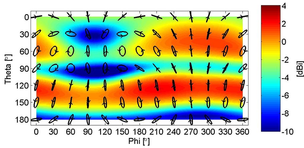
 Elevation power distribution and total incident theta- and phipolarized powers in one of the evaluated macrocell routes (transmitter at the rooftop level): 60 65 Theta polarization Phi polarization")
19 8. Enviroments used in the evaluation (cont.) Elevation power distribution and total incident theta- and phipolarized powers in one of the evaluated macrocell routes (transmitter at the rooftop level): Theta polarization Phi polarization Received power [db] MS location [m] Major part of the incident signal power arrives from the directions somewhat above the azimuth plane!! True especially at the macrocell routes
20 9. Antenna evaluation methods To simulate the random azimuth orientation of a mobile terminal, each diversity configuration was driven through each environment in 5 different azimuth positions: In order to remove slow fading, the power received by a computational isotropic shift antenna orientation shift antenna orientation y x moving direction in the environment radiator was used as a normalization y vector. The used sliding window normalization distance was 100 samples (in most cases about 2.8 m). Maximum Ratio Combining (MRC) was used to combine the signals received by the diversity branches. Branch power difference was calculated as the absolute value of the difference between the average receiver powers of the diversity branches. Envelope correlation was calculated according to the well-known definition. x 216 x y y x 288 x y
21 9. Antenna evaluation methods (cont.) Two figures of merits were used to evaluate the performance of the diversity configurations: o Diversity gain: The traditional measure of quality. Calculated as the difference between the MRC power and the stronger branch power at the level that 90 % of the signals exceed. Strongly affected by branch power difference and envelope correlation (according to theory). o MRC MEG: A new measure of quality. Determined from the MRC signal level that 50 % of the signals exceed. Indicates the median difference between the MRC power and the power received by a lossless isotropic radiator (P isotr ). Propability that power < abcissa Branch 1 Branch 2 MRC G div P isotr Normalized power [db] MRC MEG
22 10. Results Diversity gain vs. branch power difference vs. envelope correlation. Each diamond represents one diversity configuration in one enviroment. Results are grouped in 3 groupes according to the envelope correlation levels. [db] K F Q D U 3 E E Diversity gain [db] The strong effect of branch on diversity gain can clearly be seen (over 2 db decrease in diversity gain when branch increases from 0 to 5 db (red group)). As expected, also envelope correlation affects diversity gain. Different colors are clearly clustered, especially at the region where branch is below 1 db
23 10. Results (cont.) MRC MEG results for the evaluated diversity configurations in all eight environments. Blue circles present the average MRC MEGs. MRC MEG [dbi] A1 A2 A3 A4 A3HH A4HH Average MRC MEG Indoor Picocell Microcell 1 Microcell 2 Microcell 3 Macrocell 1 Macrocell 2 Macrocell 3 Highway Macrocell A1 A2 A3 A4 A3HH A4HH Total efficiency (port1/port2) [%]: 79/79 64/64 73/73 77/73 36/31 43/21 The MRC MEGs for A3HH and A4HH are very low due to the very low total efficiencies of the diversity configurations when located beside head and hand: A1 and A4 perform clearly the best from the free-space cases. WHY??

 A1,p1:")


24 10. Results (cont.) A1,p1: A1,p2: A3,p1: A3,p2: A4,p1: A4,p2:
25 10. Results (cont.) Diversity gain results for the evaluated diversity configurations in all eight environments. Blue circles present the average diversity gains. Diversity gain [db] A1 A2 A3 A4 A3HH A4HH Average Diversity Gain Indoor Picocell Microcell 1 Microcell 2 Microcell 3 Macrocell 1 Macrocell 2 Macrocell 3 Highway Macrocell Now, A1 and A4 perform the worst of the free-space cases! Since branch 1 of A1 receives much less power than branch 2, the branch power difference of A1 becomes very large. Therefore, A1 has the lowest diversity gain of the free-space cases although it was the best diversity configuration in terms of MRC MEG
26 11. Discussion and Conclusions BWBM o Fast to test antennas (+) o Radiation patterns of antennas can be rotated easily (+) o Antennas can be tested based on the simulated radiation patterns (+) o The radio channel stays exactly the same for all antenna configurations under test (+) o The physical limitations of the beamforming algorithm to estimate details of the scattering field (-) DM o More accurate to test antennas (+) o Much work is needed (-) o Prototype antennas have to be constructed for each evaluation (-) In the future: o More advanced (accurate) channel estimation algorithm should be implemented/tested
27 11. Discussion and Conclusions A new measure of quality for diversity configurations, called MRC MEG, was introduced. Branch power difference was shown to be the main contributor on diversity gain of the studied prototypes. Also, envelope correlation affected diversity gain, although the effect was smaller than the one of branch power difference. The diversity configuration with the lowest diversity gain received on average over 2.5 db more power than the configuration with the largest diversity gain!! In diversity configuration performace point of view, the total received power is the most important measure of quality MRC MEG can be considered to be a more reliable tool than diversity gain for predicting the performance of multi-antenna terminals! Diversity gain would better characterize the advantage of using additional diversity antenna if the original antenna would be used as a reference for calculating diversity gain!!!
28 References [1] P. Suvikunnas, K. Sulonen, J. Villanen, C. Icheln and P. Vainikainen, Evaluation of Performance of Multi-antenna Terminals Using Two Approaches, IEEE IMTC2004 conference, Como, Italy, May [2] J. Villanen, P. Suvikunnas, C. Icheln, J. Ollikainen and P. Vainikainen, Advances in Diversity Performance Analysis of Mobile Terminal Antennas, ISAP 2004 conference, Sendai, Japan, August
29 Homework Traditionally diversity gain has been defined as the difference between the combined signal power (e.g. MRC or EGC) and the stronger diversity branch power at some probability level. 1. What problems this kind of definition causes? Does it well describe the performance of the diversity antenna configuration? 2. How the possible problems of the traditional definition of diversity gain could be avoided?
By choosing to view this document, you agree to all provisions of the copyright laws protecting it.
 This material is posted here with permission of the IEEE. Such permission of the IEEE does not in any way imply IEEE endorsement of any of Helsinki University of Technology's products or services. Internal
ANTENNA EVALUATION. MIMO antennas and their evaluation. Antenna in a multipath environment
 MIMO antennas and their evaluation ANTENNA EVALUATION Pertti Vainikainen Helsinki Unisity of Technology Institute of Digital Communications (IDC) SMARAD Radio Laboratory 6 Sept. 5, PVa ACE MIMO course,
Effect of antenna properties on MIMO-capacity in real propagation channels
 [P5] P. Suvikunnas, K. Sulonen, J. Kivinen, P. Vainikainen, Effect of antenna properties on MIMO-capacity in real propagation channels, in Proc. 2 nd COST 273 Workshop on Broadband Wireless Access, Paris,
By choosing to view this document, you agree to all provisions of the copyright laws protecting it.
 This material is posted here with permission of the IEEE. Such permission of the IEEE does not in any way imply IEEE endorsement of any of elsinki University of Technology's products or services. Internal
STATISTICAL DISTRIBUTION OF INCIDENT WAVES TO MOBILE ANTENNA IN MICROCELLULAR ENVIRONMENT AT 2.15 GHz
 EUROPEAN COOPERATION IN COST259 TD(99) 45 THE FIELD OF SCIENTIFIC AND Wien, April 22 23, 1999 TECHNICAL RESEARCH EURO-COST STATISTICAL DISTRIBUTION OF INCIDENT WAVES TO MOBILE ANTENNA IN MICROCELLULAR
EVALUATION OF PERFORMANCE OF MOBILE TERMINAL
 Helsinki University of Technology Radio Laboratory Publications Teknillisen koerkeakoulun Radiolaboratorion julkaisuja Espoo, June, 2004 Report S 265 EVALUATION OF PERFORMANCE OF MOBILE TERMINAL ANTENNAS
Directional Radio Channel Measurements at Mobile Station in Different Radio Environments at 2.15 GHz
 Directional Radio Channel Measurements at Mobile Station in Different Radio Environments at 2.15 GHz Kimmo Kalliola 1,3, Heikki Laitinen 2, Kati Sulonen 1, Lasse Vuokko 1, and Pertti Vainikainen 1 1 Helsinki
By choosing to view this document, you agree to all provisions of the copyright laws protecting it.
 This material is posted here with permission of the IEEE. Such permission of the IEEE does not in any way imply IEEE endorsement of any of Helsinki University of Technology's products or services. Internal
Diversity Performance of an Optimized Meander PIFA Array for MIMO Handsets
 Diversity Performance of an Optimized Meander PIFA Array for MIMO Handsets Qiong Wang *, Dirk Plettemeier *, Hui Zhang *, Klaus Wolf *, Eckhard Ohlmer + * Dresden University of Technology, Chair for RF
[P8] By choosing to view this document, you agree to all provisions of the copyright laws protecting it.
![[P8] By choosing to view this document, you agree to all provisions of the copyright laws protecting it.](/thumbs/76/74145531.jpg "[P8] By choosing to view this document, you agree to all provisions of the copyright laws protecting it.") [P8] J. Villanen, P. Suvikunnas, C. Icheln, J. Ollikainen, and P. Vainikainen, Performance analysis and design aspects of mobile terminal multi-antenna configurations, IEEE Transaction on Vehicular Technology,
[P8] J. Villanen, P. Suvikunnas, C. Icheln, J. Ollikainen, and P. Vainikainen, Performance analysis and design aspects of mobile terminal multi-antenna configurations, IEEE Transaction on Vehicular Technology,
[P1] By choosing to view this document, you agree to all provisions of the copyright laws protecting it.
![[P1] By choosing to view this document, you agree to all provisions of the copyright laws protecting it.](/thumbs/82/86261411.jpg "[P1] By choosing to view this document, you agree to all provisions of the copyright laws protecting it.") [P1] K. Sulonen, P. Suvikunnas, L. Vuokko, J. Kivinen, P. Vainikainen, Comparison of MIMO antenna configurations in picocell and microcell environments, IEEE Journal on Selected Areas in Communications,
[P1] K. Sulonen, P. Suvikunnas, L. Vuokko, J. Kivinen, P. Vainikainen, Comparison of MIMO antenna configurations in picocell and microcell environments, IEEE Journal on Selected Areas in Communications,
The Composite Channel Method: Efficient Experimental Evaluation of a Realistic MIMO Terminal in the Presence of a Human Body
 The Composite Channel Method: Efficient Experimental Evaluation of a Realistic MIMO Terminal in the Presence of a Human Body Fredrik Harrysson, Jonas Medbo, Andreas F. Molisch, Anders J. Johansson and
Overview. Measurement Aspects of Mobile Terminal Antennas. Mobile communications antennas. Antenna Characteristics. Clemens Icheln.
 Overview Measurement Aspects of Mobile Terminal Antennas clemens.icheln@tkk.fi Introduction Small-antenna characteristics Standard measurement methods Other characterisation methods Specific error sources
Differential and Single Ended Elliptical Antennas for GHz Ultra Wideband Communication
 Differential and Single Ended Elliptical Antennas for 3.1-1.6 GHz Ultra Wideband Communication Johnna Powell Anantha Chandrakasan Massachusetts Institute of Technology Microsystems Technology Laboratory
Effectiveness of a Fading Emulator in Evaluating the Performance of MIMO Systems by Comparison with a Propagation Test
 Effectiveness of a Fading in Evaluating the Performance of MIMO Systems by Comparison with a Propagation Test A. Yamamoto *, T. Sakata *, T. Hayashi *, K. Ogawa *, J. Ø. Nielsen #, G. F. Pedersen #, J.
By choosing to view this document, you agree to all provisions of the copyright laws protecting it.
 This material is posted here with permission of the IEEE. Such permission of the IEEE does not in any way imply IEEE endorsement of any of Helsinki University of Technology's products or services. Internal
Channel Modelling ETI 085. Antennas Multiple antenna systems. Antennas in real channels. Lecture no: Important antenna parameters
 Channel Modelling ETI 085 Lecture no: 8 Antennas Multiple antenna systems Antennas in real channels One important aspect is how the channel and antenna interact The antenna pattern determines what the
Handset MIMO antenna measurement using a Spatial Fading Emulator
 Handset MIMO antenna measurement using a Spatial Fading Emulator Atsushi Yamamoto Panasonic Corporation, Japan Panasonic Mobile Communications Corporation, Japan NTT DOCOMO, INC., Japan Aalborg University,
Compact MIMO Antenna with Cross Polarized Configuration
 Proceedings of the 4th WSEAS Int. Conference on Electromagnetics, Wireless and Optical Communications, Venice, Italy, November 2-22, 26 11 Compact MIMO Antenna with Cross Polarized Configuration Wannipa
1. MIMO capacity basics
 Introduction to MIMO: Antennas & Propagation aspects Björn Lindmark. MIMO capacity basics. Physical interpretation of the channel matrix Example x in free space 3. Free space vs. multipath: when is scattering
Integration of inverted F-antennas in small mobile devices with respect to diversity and MIMO systems
 Integration of inverted F-antennas in small mobile devices with respect to diversity and MIMO systems S. Schulteis 1, C. Kuhnert 1, J. Pontes 1, and W. Wiesbeck 1 1 Institut für Höchstfrequenztechnik und
A compact dual-band dual-port diversity antenna for LTE
 Author manuscript, published in "Advanced Electromagnetics Journal (AEM) (2012) http://dx.doi.org/10.7716/aem.v1i1.42" DOI : 10.7716/aem.v1i1.42 ADVANCED ELECTROMAGNETICS, Vol. 1, No. 1, May 2012 A compact
Channel Capacity Enhancement by Pattern Controlled Handset Antenna
 RADIOENGINEERING, VOL. 18, NO. 4, DECEMBER 9 413 Channel Capacity Enhancement by Pattern Controlled Handset Antenna Hiroyuki ARAI, Junichi OHNO Yokohama National University, Department of Electrical and
Antennas Multiple antenna systems
 Channel Modelling ETIM10 Lecture no: 8 Antennas Multiple antenna systems Fredrik Tufvesson Department of Electrical and Information Technology Lund University, Sweden Fredrik.Tufvesson@eit.lth.se 2012-02-13
Presented at IEICE TR (AP )
") Sounding Presented at IEICE TR (AP 2007-02) MIMO Radio Seminar, Mobile Communications Research Group 07 June 2007 Takada Laboratory Department of International Development Engineering Graduate School of
Sounding Presented at IEICE TR (AP 2007-02) MIMO Radio Seminar, Mobile Communications Research Group 07 June 2007 Takada Laboratory Department of International Development Engineering Graduate School of
THE CAPACITY EVALUATION OF WLAN MIMO SYSTEM WITH MULTI-ELEMENT ANTENNAS AND MAXIMAL RATIO COMBINING
 THE CAPACITY EVALUATION OF WLAN MIMO SYSTEM WITH MULTI-ELEMENT ANTENNAS AND MAXIMAL RATIO COMBINING Pawel Kulakowski AGH University of Science and Technology Cracow, Poland Wieslaw Ludwin AGH University
On the Plane Wave Assumption in Indoor Channel Modelling
 On the Plane Wave Assumption in Indoor Channel Modelling Markus Landmann 1 Jun-ichi Takada 1 Ilmenau University of Technology www-emt.tu-ilmenau.de Germany Tokyo Institute of Technology Takada Laboratory
Full-Dimension MIMO Arrays with Large Spacings Between Elements. Xavier Artiga Researcher Centre Tecnològic de Telecomunicacions de Catalunya (CTTC)
") Full-Dimension MIMO Arrays with Large Spacings Between Elements Xavier Artiga Researcher Centre Tecnològic de Telecomunicacions de Catalunya (CTTC) APS/URSI 2015, 22/07/2015 1 Outline Introduction to Massive
Full-Dimension MIMO Arrays with Large Spacings Between Elements Xavier Artiga Researcher Centre Tecnològic de Telecomunicacions de Catalunya (CTTC) APS/URSI 2015, 22/07/2015 1 Outline Introduction to Massive
Study of Performance of Reference MIMO Antenna Configurations using Experimental Propagation Data
 HELSINKI UNIVERSITY OF TECHNOLOGY Faculty of Electronics, Communications and Automation UNIVERSITAT POLITÈCNICA DE CATALUNYA Escola Tècnica Superior d Enginyeria en Telecomunicació Mònica Salicrú Cortés
UWB Double-Directional Channel Sounding
 2004/01/30 Oulu, Finland UWB Double-Directional Channel Sounding - Why and how? - Jun-ichi Takada Tokyo Institute of Technology, Japan takada@ide.titech.ac.jp Table of Contents Background Antennas and
Experimental Evaluation Scheme of UWB Antenna Performance
 Tokyo Tech. Experimental Evaluation Scheme of UWB Antenna Performance Sathaporn PROMWONG Wataru HACHITANI Jun-ichi TAKADA TAKADA-Laboratory Mobile Communication Research Group Graduate School of Science
Antenna Design and Site Planning Considerations for MIMO
 Antenna Design and Site Planning Considerations for MIMO Steve Ellingson Mobile & Portable Radio Research Group (MPRG) Dept. of Electrical & Computer Engineering Virginia Polytechnic Institute & State
Compact and Low Profile MIMO Antenna for Dual-WLAN-Band Access Points
 Progress In Electromagnetics Research Letters, Vol. 67, 97 102, 2017 Compact and Low Profile MIMO Antenna for Dual-WLAN-Band Access Points Xinyao Luo *, Jiade Yuan, and Kan Chen Abstract A compact directional
Pattern-Reconfigurable Antennas Optimized for Automotive Applications
 Pattern-Reconfigurable Antennas Optimized for Automotive Applications CST European Automotive Workshop, 23.11.2015 Jerzy Kowalewski, Tobias Mahler, Thomas Zwick INSTITUT FÜR HOCHFREQUENZTECHNIK UND ELEKTRONIK
Written Exam Channel Modeling for Wireless Communications - ETIN10
 Written Exam Channel Modeling for Wireless Communications - ETIN10 Department of Electrical and Information Technology Lund University 2017-03-13 2.00 PM - 7.00 PM A minimum of 30 out of 60 points are
BROADBAND GAIN STANDARDS FOR WIRELESS MEASUREMENTS
 BROADBAND GAIN STANDARDS FOR WIRELESS MEASUREMENTS James D. Huff Carl W. Sirles The Howland Company, Inc. 4540 Atwater Court, Suite 107 Buford, Georgia 30518 USA Abstract Total Radiated Power (TRP) and
Experimental evaluation of massive MIMO at 20 GHz band in indoor environment
 This article has been accepted and published on J-STAGE in advance of copyediting. Content is final as presented. IEICE Communications Express, Vol., 1 6 Experimental evaluation of massive MIMO at GHz
ECE 476/ECE 501C/CS Wireless Communication Systems Winter Lecture 6: Fading
 ECE 476/ECE 501C/CS 513 - Wireless Communication Systems Winter 2004 Lecture 6: Fading Last lecture: Large scale propagation properties of wireless systems - slowly varying properties that depend primarily
Chapter 4 DOA Estimation Using Adaptive Array Antenna in the 2-GHz Band
 Chapter 4 DOA Estimation Using Adaptive Array Antenna in the 2-GHz Band 4.1. Introduction The demands for wireless mobile communication are increasing rapidly, and they have become an indispensable part
ECE 476/ECE 501C/CS Wireless Communication Systems Winter Lecture 6: Fading
 ECE 476/ECE 501C/CS 513 - Wireless Communication Systems Winter 2005 Lecture 6: Fading Last lecture: Large scale propagation properties of wireless systems - slowly varying properties that depend primarily
Channel Modelling ETI 085
 Channel Modelling ETI 085 Lecture no: 7 Directional channel models Channel sounding Why directional channel models? The spatial domain can be used to increase the spectral efficiency i of the system Smart
Millimetre Spherical Wave Antenna Pattern Measurements at NPL. Philip Miller May 2009
 Millimetre Spherical Wave Antenna Pattern Measurements at NPL Philip Miller May 2009 The NPL Spherical Range The NPL Spherical Range is a conventional spherical range housed within a 15 m by 7.5 m by 7.5
Eigenvalues and Eigenvectors in Array Antennas. Optimization of Array Antennas for High Performance. Self-introduction
 Short Course @ISAP2010 in MACAO Eigenvalues and Eigenvectors in Array Antennas Optimization of Array Antennas for High Performance Nobuyoshi Kikuma Nagoya Institute of Technology, Japan 1 Self-introduction
4.4. Experimental Results and Analysis
 4.4. Experimental Results and Analysis 4.4.1 Measurement of the IFA Against a Large Ground Plane The Inverted-F Antenna (IFA) discussed in Section 4.3.1 was modeled over an infinite ground plane using
Design of a 915 MHz Patch Antenna with structure modification to increase bandwidth
 Fidel Amezcua Professor: Ray Kwok Electrical Engineering 172 28 May 2010 Design of a 915 MHz Patch Antenna with structure modification to increase bandwidth 1. Introduction The objective presented in this
"Communications in wireless MIMO channels: Channel models, baseband algorithms, and system design"
 Postgraduate course on "Communications in wireless MIMO channels: Channel models, baseband algorithms, and system design" Lectures given by Prof. Markku Juntti, University of Oulu Prof. Tadashi Matsumoto,
5G Antenna Design & Network Planning
 5G Antenna Design & Network Planning Challenges for 5G 5G Service and Scenario Requirements Massive growth in mobile data demand (1000x capacity) Higher data rates per user (10x) Massive growth of connected
Comparison of Different MIMO Antenna Arrays and User's Effect on. their Performances
 Comparison of Different MIMO Antenna Arrays and User's Effect on their Performances Carlos Gómez-Calero, Nima Jamaly, Ramón Martínez, Leandro de Haro Keyterms Multiple-Input Multiple-Output, diversity
ECE 476/ECE 501C/CS Wireless Communication Systems Winter Lecture 6: Fading
 ECE 476/ECE 501C/CS 513 - Wireless Communication Systems Winter 2003 Lecture 6: Fading Last lecture: Large scale propagation properties of wireless systems - slowly varying properties that depend primarily
Antenna Array with Low Mutual Coupling for MIMO-LTE Applications
 Antenna Array with Low Mutual Coupling for MIMO-LTE Applications Eduardo Rodríguez Araque 1, Ezdeen Elghannai 2, Roberto G. Rojas 3 and Roberto Bustamante 4 1 Foundation Universitary Cafam (Unicafam),
Rec. ITU-R F RECOMMENDATION ITU-R F *
 Rec. ITU-R F.162-3 1 RECOMMENDATION ITU-R F.162-3 * Rec. ITU-R F.162-3 USE OF DIRECTIONAL TRANSMITTING ANTENNAS IN THE FIXED SERVICE OPERATING IN BANDS BELOW ABOUT 30 MHz (Question 150/9) (1953-1956-1966-1970-1992)
Diversity. Spring 2017 ELE 492 FUNDAMENTALS OF WIRELESS COMMUNICATIONS 1
 Diversity Spring 2017 ELE 492 FUNDAMENTALS OF WIRELESS COMMUNICATIONS 1 Diversity A fading channel with an average SNR has worse BER performance as compared to that of an AWGN channel with the same SNR!.
Channel Modelling ETIN10. Directional channel models and Channel sounding
 Channel Modelling ETIN10 Lecture no: 7 Directional channel models and Channel sounding Ghassan Dahman / Fredrik Tufvesson Department of Electrical and Information Technology Lund University, Sweden 2014-02-17
Parameter Estimation of Double Directional Radio Channel Model
 Parameter Estimation of Double Directional Radio Channel Model S-72.4210 Post-Graduate Course in Radio Communications February 28, 2006 Signal Processing Lab./SMARAD, TKK, Espoo, Finland Outline 2 1. Introduction
SPHERICAL NEAR-FIELD MEASUREMENTS AT UHF FREQUENCIES WITH COMPLETE UNCERTAINTY ANALYSIS
 SPHERICAL NEAR-FIELD MEASUREMENTS AT UHF FREQUENCIES WITH COMPLETE UNCERTAINTY ANALYSIS Allen Newell, Patrick Pelland Nearfield Systems Inc. 19730 Magellan Drive, Torrance, CA 90502-1104 Brian Park, Ted
Dual Antenna Terminals in an Indoor Scenario
 Dual Antenna Terminals in an Indoor Scenario Fredrik Harrysson, Henrik Asplund, Mathias Riback and Anders Derneryd Ericsson Research, Ericsson AB, Sweden Email: {fredrik.harrysson, henrik.asplund, mathias.riback,
Publication V Institute of Electrical and Electronics Engineers (IEEE)
") Publication V Joonas Krogerus, Juha Toivanen, Clemens Icheln, and Pertti Vainikainen. 2007. Effect of the human body on total radiated power and the 3 D radiation pattern of mobile handsets. IEEE Transactions
Publication V Joonas Krogerus, Juha Toivanen, Clemens Icheln, and Pertti Vainikainen. 2007. Effect of the human body on total radiated power and the 3 D radiation pattern of mobile handsets. IEEE Transactions
Analysis of RF requirements for Active Antenna System
 212 7th International ICST Conference on Communications and Networking in China (CHINACOM) Analysis of RF requirements for Active Antenna System Rong Zhou Department of Wireless Research Huawei Technology
Detection of Multipath Propagation Effects in SAR-Tomography with MIMO Modes
 Detection of Multipath Propagation Effects in SAR-Tomography with MIMO Modes Tobias Rommel, German Aerospace Centre (DLR), tobias.rommel@dlr.de, Germany Gerhard Krieger, German Aerospace Centre (DLR),
PERFORMANCE OF TWO BRANCH SPACE AND POLARIZATION DIVERSITY AT 900 MHZ. 1
 PERFORMACE OF TWO BRACH SPACE AD POLARIZATIO DIVERSITY AT 900 MHZ. Silvia Ruiz-Boqué, Marc.Vilades, J.Rodriguez Dep. Teoria del Senyal i Comunicacions, ETSETB, Barcelona, Spain E-mail: silvia@xaloc.upc.es
SCATTERING POLARIMETRY PART 1. Dr. A. Bhattacharya (Slide courtesy Prof. E. Pottier and Prof. L. Ferro-Famil)
") SCATTERING POLARIMETRY PART 1 Dr. A. Bhattacharya (Slide courtesy Prof. E. Pottier and Prof. L. Ferro-Famil) 2 That s how it looks! Wave Polarisation An electromagnetic (EM) plane wave has time-varying
SCATTERING POLARIMETRY PART 1 Dr. A. Bhattacharya (Slide courtesy Prof. E. Pottier and Prof. L. Ferro-Famil) 2 That s how it looks! Wave Polarisation An electromagnetic (EM) plane wave has time-varying
Diversity gain measurements for body-centric communication systems
 283 Diversity gain measurements for body-centric communication systems A.A. Serra*, A. Guraliuc +, P. Nepa +, G. Manara +, I. Khan**, P.S. Hall** + *Dept. of Information Engineering University of Pisa,
ON THE PERFORMANCE OF MIMO SYSTEMS FOR LTE DOWNLINK IN UNDERGROUND GOLD MINE
 Progress In Electromagnetics Research Letters, Vol. 30, 59 66, 2012 ON THE PERFORMANCE OF MIMO SYSTEMS FOR LTE DOWNLINK IN UNDERGROUND GOLD MINE I. B. Mabrouk 1, 2 *, L. Talbi1 1, M. Nedil 2, and T. A.
3D MIMO Outdoor-to-Indoor Propagation Channel Measurement
 1 3D MIMO Outdoor-to-Indoor Propagation Channel Measurement V. Kristem, S. Sangodoyin, Student Member, IEEE, C. U. Bas, Student Member, IEEE, M. Käske, J. Lee, Senior Member, IEEE, C. Schneider, G. Sommerkorn,
Ave output power ANT 1(dBm) Ave output power ANT 2 (dbm)
 Ave output power ANT 2 (dbm)") Page 41 of 103 9.6. Test Result The test was performed with 802.11b Channel Frequency (MHz) power ANT 1(dBm) power ANT 2 (dbm) power ANT 1(mW) power ANT 2 (mw) Limits dbm / W Low 2412 7.20 7.37 5.248 5.458
Page 41 of 103 9.6. Test Result The test was performed with 802.11b Channel Frequency (MHz) power ANT 1(dBm) power ANT 2 (dbm) power ANT 1(mW) power ANT 2 (mw) Limits dbm / W Low 2412 7.20 7.37 5.248 5.458
Antenna arrangements realizing a unitary matrix for 4 4 LOS-MIMO system
 Antenna arrangements realizing a unitary matrix for 4 4 LOS-MIMO system Satoshi Sasaki a), Kentaro Nishimori b), Ryochi Kataoka, and Hideo Makino Graduate School of Science and Technology, Niigata University,
3D Channel Propagation in an Indoor Scenario with Tx Rooftop & Wall at 3.5 & 6 GHz
 ICC217: WS8-3rd International Workshop on Advanced PHY and MAC Technology for Super Dense Wireless Networks CROWD-NET. 3D Channel Propagation in an Indoor Scenario with Tx Rooftop & Wall at 3.5 & 6 GHz
IEEE Working Group on Mobile Broadband Wireless Access <http://grouper.ieee.org/groups/802/mbwa>
 2003-01-10 IEEE C802.20-03/09 Project Title IEEE 802.20 Working Group on Mobile Broadband Wireless Access Channel Modeling Suitable for MBWA Date Submitted Source(s)
Antenna Measurement Software Features and Specifications
 Antenna Measurement Software Antenna emission measurement and characterization http://www.diamondeng.net 484 Main Street, Suite 16 Diamond Springs, CA 95619 (530) 626-3857 Software Features Test Equipment
Ray-Tracing Urban Picocell 3D Propagation Statistics for LTE Heterogeneous Networks
 13 7th European Conference on Antennas and Propagation (EuCAP) Ray-Tracing Urban Picocell 3D Propagation Statistics for LTE Heterogeneous Networks Evangelos Mellios, Geoffrey S. Hilton and Andrew R. Nix
THE EFFECTS OF NEIGHBORING BUILDINGS ON THE INDOOR WIRELESS CHANNEL AT 2.4 AND 5.8 GHz
 THE EFFECTS OF NEIGHBORING BUILDINGS ON THE INDOOR WIRELESS CHANNEL AT.4 AND 5.8 GHz Do-Young Kwak*, Chang-hoon Lee*, Eun-Su Kim*, Seong-Cheol Kim*, and Joonsoo Choi** * Institute of New Media and Communications,
MIMO Channel Modeling and Capacity Analysis for 5G Millimeter-Wave Wireless Systems
 M. K. Samimi, S. Sun, T. S. Rappaport, MIMO Channel Modeling and Capacity Analysis for 5G Millimeter-Wave Wireless Systems, in the 0 th European Conference on Antennas and Propagation (EuCAP 206), April
MIMO Capacity in a Pedestrian Passageway Tunnel Excited by an Outside Antenna
 MIMO Capacity in a Pedestrian Passageway Tunnel Excited by an Outside Antenna J. M. MOLINA-GARCIA-PARDO*, M. LIENARD**, P. DEGAUQUE**, L. JUAN-LLACER* * Dept. Techno. Info. and Commun. Universidad Politecnica
A New Fractal Based PIFA Antenna Design for MIMO Dual Band WLAN Applications
 University of Technology, Iraq From the SelectedWorks of Professor Jawad K. Ali March 27, 2012 A New Fractal Based PIFA Antenna Design for MIMO Dual Band WLAN Applications Ali J Salim, Department of Electrical
Research Article Modified Spatial Channel Model for MIMO Wireless Systems
 Hindawi Publishing Corporation EURASIP Journal on Wireless Communications and Networking Volume 27, Article ID 682, 7 pages doi:/27/682 Research Article Modified Spatial Channel Model for MIMO Wireless
Cross-correlation Characteristics of Multi-link Channel based on Channel Measurements at 3.7GHz
 Cross-correlation Characteristics of Multi-link Channel based on Channel Measurements at 3.7GHz Myung-Don Kim*, Jae Joon Park*, Hyun Kyu Chung* and Xuefeng Yin** *Wireless Telecommunications Research Department,
Multi-Path Fading Channel
 Instructor: Prof. Dr. Noor M. Khan Department of Electronic Engineering, Muhammad Ali Jinnah University, Islamabad Campus, Islamabad, PAKISTAN Ph: +9 (51) 111-878787, Ext. 19 (Office), 186 (Lab) Fax: +9
Using Frequency Diversity to Improve Measurement Speed Roger Dygert MI Technologies, 1125 Satellite Blvd., Suite 100 Suwanee, GA 30024
 Using Frequency Diversity to Improve Measurement Speed Roger Dygert MI Technologies, 1125 Satellite Blvd., Suite 1 Suwanee, GA 324 ABSTRACT Conventional antenna measurement systems use a multiplexer or
THE EFFECT of Rayleigh fading due to multipath propagation
 IEEE TRANSACTIONS ON VEHICULAR TECHNOLOGY, VOL. 47, NO. 3, AUGUST 1998 755 Signal Correlations and Diversity Gain of Two-Beam Microcell Antenna Jukka J. A. Lempiäinen and Keijo I. Nikoskinen Abstract The
Performance of Closely Spaced Multiple Antennas for Terminal Applications
 Performance of Closely Spaced Multiple Antennas for Terminal Applications Anders Derneryd, Jonas Fridén, Patrik Persson, Anders Stjernman Ericsson AB, Ericsson Research SE-417 56 Göteborg, Sweden {anders.derneryd,
TRI-BAND COMPACT ANTENNA ARRAY FOR MIMO USER MOBILE TERMINALS AT GSM 1800 AND WLAN BANDS
 Microwave Opt Technol Lett 50: 1914-1918, 2008; Published online in Wiley InterScience (www.interscience.wiley.com). DOI 10.1002/mop. 23472 Key words: planar inverted F-antenna; MIMO; WLAN; capacity 1.
The Measurement and Characterisation of Ultra Wide-Band (UWB) Intentionally Radiated Signals
 Intentionally Radiated Signals") The Measurement and Characterisation of Ultra Wide-Band (UWB) Intentionally Radiated Signals Rafael Cepeda Toshiba Research Europe Ltd University of Bristol November 2007 Rafael.cepeda@toshiba-trel.com
The Measurement and Characterisation of Ultra Wide-Band (UWB) Intentionally Radiated Signals Rafael Cepeda Toshiba Research Europe Ltd University of Bristol November 2007 Rafael.cepeda@toshiba-trel.com
Interference Scenarios and Capacity Performances for Femtocell Networks
 Interference Scenarios and Capacity Performances for Femtocell Networks Esra Aycan, Berna Özbek Electrical and Electronics Engineering Department zmir Institute of Technology, zmir, Turkey esraaycan@iyte.edu.tr,
FDM based MIMO Spatio-Temporal Channel Sounder
 FDM based MIMO Spatio-Temporal Channel Sounder Graduate School of Science and Technology, Kazuhiro Kuroda, Kei Sakaguchi, Jun-ichi Takada, Kiyomichi Araki Motivation The performance of MIMO communication
Channel. Muhammad Ali Jinnah University, Islamabad Campus, Pakistan. Multi-Path Fading. Dr. Noor M Khan EE, MAJU
 Instructor: Prof. Dr. Noor M. Khan Department of Electronic Engineering, Muhammad Ali Jinnah University, Islamabad Campus, Islamabad, PAKISTAN Ph: +9 (51) 111-878787, Ext. 19 (Office), 186 (Lab) Fax: +9
REALISTIC ANTENNA ELEMENTS AND DIFFERENT ARRAY TOPOLOGIES IN THE DOWNLINK OF UMTS-FDD NETWORKS
 REALISTIC ANTENNA ELEMENTS AND DIFFERENT ARRAY TOPOLOGIES IN THE DOWNLINK OF UMTS-FDD NETWORKS S. Bieder, L. Häring, A. Czylwik, P. Paunov Department of Communication Systems University of Duisburg-Essen
SAGE Millimeter, Inc.
 Description: Model SAM-5735930395-15-L1-4W is a linear polarized, 58 GHz microstrip patch 1 x 4 array antenna. The antenna array implements four individual antenna ports so that beamforming can be achieved
Compact Multifunctional Dipole Antenna Array for MIMO Systems. A Thesis. Submitted to the Faculty. Drexel University
 Compact Multifunctional Dipole Antenna Array for MIMO Systems A Thesis Submitted to the Faculty of Drexel University by Mikhail Aleksandrovich Chernyavskiy in partial fulfillment of the requirements for
Research Article Analysis of MIMO Diversity Improvement Using Circular Polarized Antenna
 Antennas and Propagation, Article ID 5793, 9 pages http://dx.doi.org/1.1155/14/5793 Research Article Analysis of MIMO Diversity Improvement Using Circular Polarized Antenna Jianquan Wang, Zhaobiao Lv,
4GHz / 6GHz Radiation Measurement System
 4GHz / 6GHz Radiation Measurement System The MegiQ Radiation Measurement System (RMS) is a compact test system that performs 3-axis radiation pattern measurement in non-anechoic spaces. With a frequency
EEM.Ant. Antennas and Propagation
 EEM.ant/0304/08pg/Req: None 1/8 UNIVERSITY OF SURREY Department of Electronic Engineering MSc EXAMINATION EEM.Ant Antennas and Propagation Duration: 2 Hours Spring 2003/04 READ THESE INSTRUCTIONS Answer
Project: IEEE P Working Group for Wireless Personal Area Networks N
 Project: IEEE P82.15 Working Group for Wireless Personal Area Networks N (WPANs( WPANs) Title: [UWB Channel Model for Indoor Residential Environment] Date Submitted: [2 September, 24] Source: [Chia-Chin
Modeling Mutual Coupling and OFDM System with Computational Electromagnetics
 Modeling Mutual Coupling and OFDM System with Computational Electromagnetics Nicholas J. Kirsch Drexel University Wireless Systems Laboratory Telecommunication Seminar October 15, 004 Introduction MIMO
Spherical Arrays for Wireless Channel Characterization and Emulation Franek, Ondrej; Pedersen, Gert F.
 Aalborg Universitet Spherical Arrays for Wireless Channel Characterization and Emulation Franek, Ondrej; Pedersen, Gert F. Published in: Antennas and Propagation in Wireless Communications (APWC), 2014
LETTER Numerical Analysis on MIMO Performance of the Modulated Scattering Antenna Array in Indoor Environment
 1752 LETTER Numerical Analysis on MIMO Performance of the Modulated Scattering Antenna Array in Indoor Environment Lin WANG a), Student Member,QiangCHEN, Qiaowei YUAN, Members, and Kunio SAWAYA, Fellow
Radio Channel Measurements With Relay Link at 780 MHz in an Outdoor to Indoor Propagation Environment
 Radio Channel Measurements With Relay Link at 780 MHz in an Outdoor to Indoor Propagation Environment Essi Suikkanen Centre for Wireless Communications University of Oulu Outline Motivation for the Measurements
MIMO I: Spatial Diversity
 MIMO I: Spatial Diversity COS 463: Wireless Networks Lecture 16 Kyle Jamieson [Parts adapted from D. Halperin et al., T. Rappaport] What is MIMO, and why? Multiple-Input, Multiple-Output (MIMO) communications
Radio channel modeling: from GSM to LTE
 Radio channel modeling: from GSM to LTE and beyond Alain Sibille Telecom ParisTech Comelec / RFM Outline Introduction: why do we need channel models? Basics Narrow band channels Wideband channels MIMO
Keysight Technologies Theory, Techniques and Validation of Over-the-Air Test Methods
 Keysight Technologies Theory, Techniques and Validation of Over-the-Air Test Methods For Evaluating the Performance of MIMO User Equipment Application Note Abstract Several over-the-air (OTA) test methods
This is the author s final accepted version.
 Abbasi, Q. H., El Sallabi, H., Serpedin, E., Qaraqe, K., Alomainy, A. and Hao, Y. (26) Ellipticity Statistics of Ultra Wideband MIMO Channels for Body Centric Wireless Communication. In: th European Conference