Lecture #19 Digital To Analog, PWM, Stepper Motors Embedded System Engineering Philip Koopman Monday, 28-March-2016
|
|
|
- Eustacia Owen
- 6 years ago
- Views:
Transcription
1 Lecture #19 Digital To Analog, PWM, Stepper Motors Embedded System Engineering Philip Koopman Monday, 28-March-2016 Electrical& Computer ENGINEERING Copyright , Philip Koopman, All Rights Reserved

2 Example System: HVAC Compressor Expansion Valve [ 2
3 HVAC Embedded Control Compressors (reciprocating & scroll) Smart loading and unloading of compressor Want to minimize motor turn on/turn off cycles May involve bypassing liquid so compressor keeps running but doesn t compress Variable speed for better output temperature control Diagnostics and prognostics Prevent equipment damage (e.g., liquid entering compressor, compressor stall) Predict equipment failures (e.g., low refrigerant, motor bearings wearing out) Expansion Valve Smart control of amount of refrigerant evaporated Often a stepper motor Diagnostics and prognostics Low refrigerant, icing on cold coils, overheating of hot coils System coordination Coordinate expansion valve and compressor operation Coordinate multiple compressors Next lecture talk about building-level system level diagnostics & coordination 3
4 Where Are We Now? Where we ve been: Interrupts, concurrency, scheduling, RTOS Where we re going today: Analog Output Where we re going next: Analog Input Human I/O Very gentle introduction to control Test #2 and last project demo 4
5 Preview Digital To Analog Conversion Example implementation Understanding performance Low pass filters Waveform encoding PWM Digital way to fake analog How to use course processor PWM support hardware How a servo works How a stepper motor works Note: 3-D printers are mostly stepper motors + PWM 5
6 Big Picture I/O Is Where The Work Gets Done! FPGA/ ASIC MEMORY SOFTWARE MICROCONTROLLER SENSORS A/D CONVERSION CPU D/A CONVERSION ACTUATORS HUMAN INTERFACE DIAGNOSTIC TOOLS AUXILIARY SYSTEMS (POWER, COOLING) ELECTROMECHANICAL BACKUP & SAFETY EXTERNAL ENVIRONMENT 6
7 Analog Digital Analog Conversion The real world is analog Voltage, current are continuous Time is continuous But the computing world is discrete Bits, bytes Some sensors/actuators use digital values but many deal with analog values A/D conversion analog to digital Getting analog inputs to digital form D/A conversion digital to analog Getting digital inputs to analog form Digital I/O Sometimes you can fake analog values with digital (e.g., digital pulsing) 7
8 D/A Conversion DAC = D/A Converter = Digital To Analog Converter Given several bits of a digital value, convert it to an analog value Usually voltage or current Many drives an actuator, further converting output into motion, heat, light, etc. Might be directly connected to CPU or accessed via a serial bus [Valvano] 8
9 General Idea Of A DAC Input is bits k-bit value, often 8 bits but can be any integer number Signed or unsigned number (often unsigned) Output is an analog value (volts, amps) Digital value determines output Can be output many ways: Absolute voltage Offset added to reference voltage Current (mamps, Amps) Analog Signal 3V 0V } Analog Digital Conversion Digital Representation Digital Value 3.0V 2.8V 2.6V 2.4V 2.2V 2.0V 1.8V 1.6V 1.4V 1.2V 1.0V 0.8V 0.6V 0.4V 0.2V 0.0V 9
10 Analog Circuits Aren t Ideal Real DACs have offset error, gain error, slew, ringing, nonlinearities [Valvano] [Valvano] 10
11 Example 3-Bit DAC Operating Principle for Summing DAC : One switch per bit; bit closes switch when on ; opens switch when off Different resistor values put different voltages out Net resistance (hence input voltage) subject to parallel resistance value Note: each resistor 2x previous resistor Each bit contributes half the voltage of the next higher bit [Valvano] 11
12 DAC Performance Usually, DACs attempt to be linear: b7 b6 b5 b4 b3 b2 b1 b0 V out V fullscale V Notes: V fullscale input in this equation has to be 1/256 above output full scale If all these bits are on, result is 255/256 of V fullscale V offset is supposed to be zero in most applications Doesn t take into account non-ideal behaviors! Quantization effects value Analog value isn t exact Analog value is approximated via a bin or voltage quantum Bin size is ~1/2 K of full scale (not quite because of the fencepost numbering issue) offset Quantization effects time Analog value produced periodically by CPU Not continuously as with real analog signal! 12
13 Generating An Analog Waveform Computed Periodic output values Use timer-based interrupt (What is the problem with this particular example from Valvano?) [Valvano] 13
14 Generating An Analog Waveform Table Based [Valvano] 14
15 Encoding Waveforms PCM Sample rate how often are the samples? Want samples at least twice as fast as highest frequency component (a.k.a. Nyquist Rate) PCM Pulse Code Modulation Use the binary value in each sample Use as an unsigned value Typically put zero point in middle E.g. 0-15; 7 = 0 Volts 0 = -5 Volts Example: CD-Audio is 16-bit PCM at 44 KHz (stereo two channels) Why 44 KHz? Analog Signal PCM Encoded Values 7 = 0 Volts PCM Encoded Values [Wikipedia:PCM], modified 15
16 Delta Modulation Delta Modulation Use the difference from last sample Uses fewer bits per sample but assumes signal changes gradually Bits per sample related to bandwidth of signal higher bandwidth means bigger deltas (more bits per sample) Example on right is, perhaps, 3 bit encoding: { -4, -3, -2, -1, 0, 1, 2, 3} Values are twos complement rather than unsigned Values must be added to running total (i.e., integrated) Analog Signal +2 +1, 0 0, , 0, -1 7 = 0 Volts Delta Encoded Values Other more sophisticated encodings Linear predictive coding Application-specific coding (MP3, etc.) 16
17 It s All About The Bandwidth Bits Per Second Increasing # bits of resolution improves output waveform Reduces value quantization error [Valvano] Increasing sample rate improves output waveform Reduces time quantization error PICTURES REVERSED [Valvano] 17
18 Low Pass Filters Can we get rid of the bumps in the output? Add more bits (expensive, doesn t necessarily work very well)..or.. Use a Low Pass Filter! [Wikipedia] Or, sometimes do nothing (implicit low pass filter) Physical time constants of controlled system or actuators might smooth bumps! 18
19 Pulse Modulation DACs are expensive take a lot of area And even more if you want lots of analog output channels! The course processor doesn t even have D/A outputs built into it So, how do you actually do D/A conversion without a DAC? Preferably using a single output pin? Preferably in a way that is lower noise than a DAC (e.g., purely digital) Can use purely digital output to fake analog output Pulse Density Modulation Use high speed bit stream to represent proportion of full scale value Pulse Width Modulation Send varying width of pulses to change power/duty cycle of actuator Others: Pulse Rate modulation (how often a pulse is sent) 19
20 Pulse Density Modulation Look at a sliding window of p pulses Bit value of 1 = +1 Bit value of 0 = -1 Signal value is the sum of the +1 and -1 values of the bits in the window Generally want very high bit rate for this to work (used in audio systems) Works on AC signals; can have offset error on slow or DC signals Get analog output with LP Filter (capacitor does analog work) Sliding Window [Wikipedia:PDM] How do you know signal is going down just after the peak? When first -1 enters sliding window, output starts going down Output is phase-shifted to the right by the sliding window size 20
21 PDM Implementation Sketch for(;;) { { if (<next sample time>) { <update desired_output> } if (desired_output > current_output) { output(1); // Go up if we are currently too low current_output += delta_value; } else { output(0); // Go down if we are currently too high current_output = delta_value; } <wait for next output bit time; constant bit rate> } Tradeoffs: With only two values, analog noise less of an issue (only hi and lo ) Direct tradeoff of value quantization vs. time quantization Big window gives more values, but takes longer to make big changes Small window has less phase shift, but supports fewer total values It s all about the bandwidth bits per second is the limiting factor 21

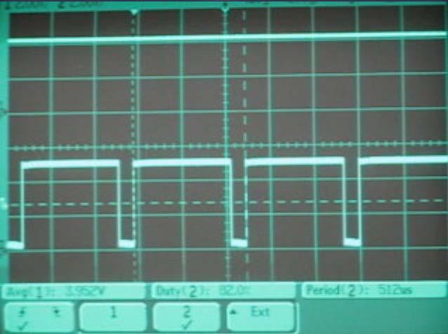
22 Pulse Width Modulation Idea: represent value with high/low duty cycle Constant period, some high and some low within period e.g., 30% duty cycle: 3 msec high, 7 msec low (10 msec period) e.g., 90% duty cycle: 90 msec high, 10 msec low (100 msec period) Can be used to deliver varying levels of power This is how LED dimming works Often relies on time constant of actuator to do LP Filtering for free Can be used, for example, to control cooling fan speed Physical inertia of the fan integrates pulses into an average fan speed [Barr01] 22
23 23
24 PWM Block Diagram See Chapter 12 of MC8S12 data sheet for details 24
25 PWM Registers MODRRx Timer vs. PWM channel x (1 = PWM) PWMEx enable PWM channel x (1 PWM) PWMPOLx polarity 0 = low followed by high (first part of pulse is low) 1 = high followed by low (first part of pulse is high) PWMPRCLK clock prescaler (similar to other clock prescalers) PWMCLK clock select for PWM (Clock A/B or Clock SA/SB) Clocks SA/SB are scaled versions of Clock A, Clock B E.g., PWMSCLA is scaling value for Clock A lets it run up to 512x slower PWMCTL control register concatenation Concatenates pairs of 8-bit counters to give 16-bit counters CON23: channel 2 register is high-order byte of a 16-bit channel PWMPERx period for channel PWMDTYx duty cycle for channel PWMSDN optional pin for emergency shutdown of pulses Interrupt vector $FF8C Why do you want emergency shutdown of pulses? 25
26 [Valvano]

27 How Do Servos Work? Uses PWM to set position between zero and full PWM sets commanded position Potentiometer used to measure actual position Servo self-adjusts to keep actual position at/near commanded position Closed loop control; maintains position even if external forces try to move servo 27
28 Is PWM A Free Ride? Digital values have very low amplitude noise Analog values noise shows up in any disturbance Digital values noise only if signal crosses threshold Is it a free lunch? No still have noise in timing Clock edges can move around depending on value noise, ringing, etc. Quantization noise in timing Based on PWM clocks putting edge in the right place Based on PDM having consistent clock lengths Need enough bits in the PWM counter to manage cimting (8 bits or 16 bits) If you are receiving PWM with a digital device need to do pulse capture Done using Pulse Accumulator hardware (or relevant software) Can be used to measure frequency (time between edges) Can be used to measure duty cycle (proportion of high to low times) This is in Valvano, but not something we ll cover beyond this mention 28

29 Solonoids Used to generate a short-stroke linear motion Release driven by spring, gravity, or second solonoid on same armature 29
")
30 Stepper Motors Many simple embedded systems use stepper motors Uses a digital (on/off) interface Permits rotating motor to one of a set of rotational positions Gives good positional stability without use of shaft encoder/feedback General motor control is a whole other lecture (or set of lectures) [Valvano] 30
 Resolution: 20 steps per revolution 18 degrees per step 200 steps per revolution 1.")
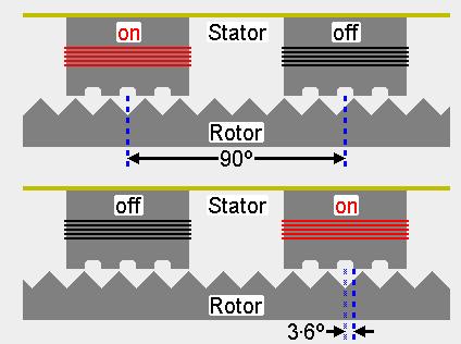
31 Stepper Motor General Idea Magnetic rotors spin, driven by electromagnetic stators Stator Poles alternate North and South to force motors to spin (animation on following slides) Resolution: 20 steps per revolution 18 degrees per step 200 steps per revolution 1.8 degrees per step # steps per revolution = # stator coils (phases) * # teeth [Valvano] 31

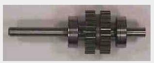
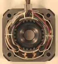
32 Photos Of Stepper Motors 32
33 [Valvano] 33
34 [Valvano] 34
35 [Valvano] 35
36 [Valvano] 36

37 Stepper Motor Ramp Up & Ramp Down Stepper motor changes speed as it moves Magnetic pole changes have to coordinate with current speed Motor spec & math gives you a speed profile [Austin04] What happens if you don t know where you are? Lose power Controller resets Something jams and you lose steps? 37
38 Stepper Motor Drive Circuit Note: not the same motor type as other Valvano pictures A/A and B/B are always a high/low pair High turns coil on; Low turns coil off 1N914 diodes protect against back-emf overvoltage when turning coil off [Valvano] 38

39 Stepper Motors Are A Robot Gateway Device Makerbot stepper motors to position things The vibration from making steps makes noise. Can you do something fun with that? 39
40 Review Digital To Analog Conversion Example implementation how DAC actually works Performance aspects: especially quantization issues Encoding waveforms to feed to a DAC Low pass filter on outputs Pulse Modulation Pulse Density Modulation vs. Pulse Width Modulation How PWM works in general For lab, be able to program the PWM hardware How a servo works Stepper motor Simplest kind of motor to use; have an idea of what s going on with phases And how a solonoid works 40
Assembly Language. Topic 14 Motion Control. Stepper and Servo Motors
 Assembly Language Topic 14 Motion Control Stepper and Servo Motors Objectives To gain an understanding of the operation of a stepper motor To develop a means to control a stepper motor To gain an understanding
Sensors and Sensing Motors, Encoders and Motor Control
 Sensors and Sensing Motors, Encoders and Motor Control Todor Stoyanov Mobile Robotics and Olfaction Lab Center for Applied Autonomous Sensor Systems Örebro University, Sweden todor.stoyanov@oru.se 13.11.2014
Lab Exercise 9: Stepper and Servo Motors
 ME 3200 Mechatronics Laboratory Lab Exercise 9: Stepper and Servo Motors Introduction In this laboratory exercise, you will explore some of the properties of stepper and servomotors. These actuators are
Lecture #20 Analog Inputs Embedded System Engineering Philip Koopman Wednesday, 30-March-2016
 Lecture #20 Analog Inputs 18-348 Embedded System Engineering Philip Koopman Wednesday, 30-March-2016 Electrical& Computer ENGINEEING Copyright 2006-2016, Philip Koopman, All ights eserved Commercial HVAC
MSK4310 Demonstration
 MSK4310 Demonstration The MSK4310 3 Phase DC Brushless Speed Controller hybrid is a complete closed loop velocity mode controller for driving a brushless motor. It requires no external velocity feedback
2.017 DESIGN OF ELECTROMECHANICAL ROBOTIC SYSTEMS Fall 2009 Lab 4: Motor Control. October 5, 2009 Dr. Harrison H. Chin
 2.017 DESIGN OF ELECTROMECHANICAL ROBOTIC SYSTEMS Fall 2009 Lab 4: Motor Control October 5, 2009 Dr. Harrison H. Chin Formal Labs 1. Microcontrollers Introduction to microcontrollers Arduino microcontroller
DC motor control using arduino
 DC motor control using arduino 1) Introduction: First we need to differentiate between DC motor and DC generator and where we can use it in this experiment. What is the main different between the DC-motor,
Sensors and Sensing Motors, Encoders and Motor Control
 Sensors and Sensing Motors, Encoders and Motor Control Todor Stoyanov Mobile Robotics and Olfaction Lab Center for Applied Autonomous Sensor Systems Örebro University, Sweden todor.stoyanov@oru.se 05.11.2015
Lock Cracker S. Lust, E. Skjel, R. LeBlanc, C. Kim
 Lock Cracker S. Lust, E. Skjel, R. LeBlanc, C. Kim Abstract - This project utilized Eleven Engineering s XInC2 development board to control several peripheral devices to open a standard 40 digit combination
Analog I/O. ECE 153B Sensor & Peripheral Interface Design Winter 2016
 Analog I/O ECE 153B Sensor & Peripheral Interface Design Introduction Anytime we need to monitor or control analog signals with a digital system, we require analogto-digital (ADC) and digital-to-analog
Optimizing Performance Using Slotless Motors. Mark Holcomb, Celera Motion
 Optimizing Performance Using Slotless Motors Mark Holcomb, Celera Motion Agenda 1. How PWM drives interact with motor resistance and inductance 2. Ways to reduce motor heating 3. Locked rotor test vs.
combine regular DC-motors with a gear-box and an encoder/potentiometer to form a position control loop can only assume a limited range of angular
 Embedded Control Applications II MP10-1 Embedded Control Applications II MP10-2 week lecture topics 10 Embedded Control Applications II - Servo-motor control - Stepper motor control - The control of a
L E C T U R E R, E L E C T R I C A L A N D M I C R O E L E C T R O N I C E N G I N E E R I N G
 P R O F. S L A C K L E C T U R E R, E L E C T R I C A L A N D M I C R O E L E C T R O N I C E N G I N E E R I N G G B S E E E @ R I T. E D U B L D I N G 9, O F F I C E 0 9-3 1 8 9 ( 5 8 5 ) 4 7 5-5 1 0
EE 308 Spring Using the HCS12 PWM
 Using the HCS12 PWM 1. Choose 8-bit mode (PWMCTL = x) 2. Choose high polarity (PWMPOL = xff) 3. Choose left-aligned (PWMCAE = x) 4. Select clock mode in PWMCLK: PCLKn = for 2 N, PCLKn = 1 for 2 (N+1) M,
Oct 30 Announcements. Bonus marked will be posted today Will provide 270 style feedback on multiple-choice questions. [3.E]-1
![Oct 30 Announcements. Bonus marked will be posted today Will provide 270 style feedback on multiple-choice questions. [3.E]-1](/thumbs/74/70719255.jpg "Oct 30 Announcements. Bonus marked will be posted today Will provide 270 style feedback on multiple-choice questions. [3.E]-1") Oct 30 Announcements Code Marked and on Blackboard This week: Mon 2:30 to 3:00pm, Tues 2:30 to 3:30 and W-F 1:30 to 3:00pm opportunity to talk about code: earn 2 extra points on the coding part Bonus marked
Oct 30 Announcements Code Marked and on Blackboard This week: Mon 2:30 to 3:00pm, Tues 2:30 to 3:30 and W-F 1:30 to 3:00pm opportunity to talk about code: earn 2 extra points on the coding part Bonus marked
Standard single-purpose processors: Peripherals
 3-1 Chapter 3 Standard single-purpose processors: Peripherals 3.1 Introduction A single-purpose processor is a digital system intended to solve a specific computation task. The processor may be a standard
ServoStep technology
 What means "ServoStep" "ServoStep" in Ever Elettronica's strategy resumes seven keypoints for quality and performances in motion control applications: Stepping motors Fast Forward Feed Full Digital Drive
University of North Carolina-Charlotte Department of Electrical and Computer Engineering ECGR 3157 Electrical Engineering Design II Fall 2013
 Exercise 1: PWM Modulator University of North Carolina-Charlotte Department of Electrical and Computer Engineering ECGR 3157 Electrical Engineering Design II Fall 2013 Lab 3: Power-System Components and
Chapter 5: Signal conversion
 Chapter 5: Signal conversion Learning Objectives: At the end of this topic you will be able to: explain the need for signal conversion between analogue and digital form in communications and microprocessors
Jaguar Motor Controller (Stellaris Brushed DC Motor Control Module with CAN)
") Jaguar Motor Controller (Stellaris Brushed DC Motor Control Module with CAN) 217-3367 Ordering Information Product Number Description 217-3367 Stellaris Brushed DC Motor Control Module with CAN (217-3367)
Jaguar Motor Controller (Stellaris Brushed DC Motor Control Module with CAN) 217-3367 Ordering Information Product Number Description 217-3367 Stellaris Brushed DC Motor Control Module with CAN (217-3367)
Advantages of Analog Representation. Varies continuously, like the property being measured. Represents continuous values. See Figure 12.
 Analog Signals Signals that vary continuously throughout a defined range. Representative of many physical quantities, such as temperature and velocity. Usually a voltage or current level. Digital Signals
EEE3410 Microcontroller Applications Department of Electrical Engineering Lecture 11 Motor Control
 EEE34 Microcontroller Applications Department of Electrical Engineering Lecture Motor Control Week 3 EEE34 Microcontroller Applications In this Lecture. Interface 85 with the following output Devices Optoisolator
Detect stepper motor stall with back EMF technique (Part 1)
") Detect stepper motor stall with back EMF technique (Part 1) Learn about this method that takes advantage of constant motor parameters and overcomes limitations of traditional stall detection of current
Detect stepper motor stall with back EMF technique (Part 1) Learn about this method that takes advantage of constant motor parameters and overcomes limitations of traditional stall detection of current
I hope you have completed Part 2 of the Experiment and is ready for Part 3.
 I hope you have completed Part 2 of the Experiment and is ready for Part 3. In part 3, you are going to use the FPGA to interface with the external world through a DAC and a ADC on the add-on card. You
Hello, and welcome to this presentation of the STM32 Digital Filter for Sigma-Delta modulators interface. The features of this interface, which
 Hello, and welcome to this presentation of the STM32 Digital Filter for Sigma-Delta modulators interface. The features of this interface, which behaves like ADC with external analog part and configurable
Page 1. Midterm #2. OpAmp Review. Inverting & Non-inverting Circuits CS/ECE 6780/5780. Al Davis. Almost ubiquitous analog circuit element since ~1968
 Midterm #2 Midterm 2 hints CS/ECE 6780/5780 Al Davis Today s topics: no practice midterm since it didn t help last time ADC s and DAC s chapter 11 of your text your kit has an A/D (Port D w/ DDR set to
ME 4447/6405 Pulse Width Modulation (PWM)
") ME 4447/6405 Pulse Width Modulation (PWM) Adam Becker Matt Eicholtz Jie Gong Dustin Li 10/28/2008 1 1 Outline Applications Analog vs. Digital Actuation Linear amplifier drawbacks Efficiency Pulse Width
ME 4447/6405 Pulse Width Modulation (PWM) Adam Becker Matt Eicholtz Jie Gong Dustin Li 10/28/2008 1 1 Outline Applications Analog vs. Digital Actuation Linear amplifier drawbacks Efficiency Pulse Width
EE251: Tuesday October 10
 EE251: Tuesday October 10 Analog to Digital Conversion Text Chapter 20 through section 20.2 TM4C Data Sheet Chapter 13 Lab #5 Writeup Lab Practical #1 this week Homework #4 is due on Thursday at 4:30 p.m.
Motors and Servos Part 2: DC Motors
 Motors and Servos Part 2: DC Motors Back to Motors After a brief excursion into serial communication last week, we are returning to DC motors this week. As you recall, we have already worked with servos
Ch 5 Hardware Components for Automation
 Ch 5 Hardware Components for Automation Sections: 1. Sensors 2. Actuators 3. Analog-to-Digital Conversion 4. Digital-to-Analog Conversion 5. Input/Output Devices for Discrete Data Computer-Process Interface
Step vs. Servo Selecting the Best
 Step vs. Servo Selecting the Best Dan Jones Over the many years, there have been many technical papers and articles about which motor is the best. The short and sweet answer is let s talk about the application.
Direct Current Waveforms
 Cornerstone Electronics Technology and Robotics I Week 20 DC and AC Administration: o Prayer o Turn in quiz Direct Current (dc): o Direct current moves in only one direction in a circuit. o Though dc must
The Fan Company Microcontroller Fan. Prepared by. JMC Engineering
 The Fan Company www.jmcproducts.com Microcontroller Fan Prepared by JMC Engineering July 2013 Introduction: Technical Report New thermal cooling challenges need new and innovative cooling solutions. Controlling
MICROCONTROLLERS Stepper motor control with Sequential Logic Circuits
 PH-315 MICROCONTROLLERS Stepper motor control with Sequential Logic Circuits Portland State University Summary Four sequential digital waveforms are used to control a stepper motor. The main objective
Robot Actuators. Motors and Control. Stepper Motor Basics. Increased Resolution. Stepper motors. DC motors AC motors. Physics review: Nature is lazy.
 obot Actuators tepper motors Motors and Control DC motors AC motors Physics review: ature is lazy. Things seek lowest energy states. iron core vs. magnet magnetic fields tend to line up Electric fields
6.111 Lecture # 19. Controlling Position. Some General Features of Servos: Servomechanisms are of this form:
 6.111 Lecture # 19 Controlling Position Servomechanisms are of this form: Some General Features of Servos: They are feedback circuits Natural frequencies are 'zeros' of 1+G(s)H(s) System is unstable if
ANALOG-TO-DIGITAL CONVERTERS
 ANALOG-TO-DIGITAL CONVERTERS Definition An analog-to-digital converter is a device which converts continuous signals to discrete digital numbers. Basics An analog-to-digital converter (abbreviated ADC,
Section 1. Fundamentals of DDS Technology
 Section 1. Fundamentals of DDS Technology Overview Direct digital synthesis (DDS) is a technique for using digital data processing blocks as a means to generate a frequency- and phase-tunable output signal
CHAPTER 4 CONTROL ALGORITHM FOR PROPOSED H-BRIDGE MULTILEVEL INVERTER
 65 CHAPTER 4 CONTROL ALGORITHM FOR PROPOSED H-BRIDGE MULTILEVEL INVERTER 4.1 INTRODUCTION Many control strategies are available for the control of IMs. The Direct Torque Control (DTC) is one of the most
A COMPARISON STUDY OF THE COMMUTATION METHODS FOR THE THREE-PHASE PERMANENT MAGNET BRUSHLESS DC MOTOR
 A COMPARISON STUDY OF THE COMMUTATION METHODS FOR THE THREE-PHASE PERMANENT MAGNET BRUSHLESS DC MOTOR Shiyoung Lee, Ph.D. Pennsylvania State University Berks Campus Room 120 Luerssen Building, Tulpehocken
CprE 288 Introduction to Embedded Systems (Output Compare and PWM) Instructors: Dr. Phillip Jones
 Instructors: Dr. Phillip Jones") CprE 288 Introduction to Embedded Systems (Output Compare and PWM) Instructors: Dr. Phillip Jones 1 Announcements HW8: Due Sunday 10/29 (midnight) Exam 2: In class Thursday 11/9 This object detection lab
CprE 288 Introduction to Embedded Systems (Output Compare and PWM) Instructors: Dr. Phillip Jones 1 Announcements HW8: Due Sunday 10/29 (midnight) Exam 2: In class Thursday 11/9 This object detection lab
Linear vs. PWM/ Digital Drives
 APPLICATION NOTE 125 Linear vs. PWM/ Digital Drives INTRODUCTION Selecting the correct drive technology can be a confusing process. Understanding the difference between linear (Class AB) type drives and
Microcontroller Based Electric Expansion Valve Controller for Air Conditioning System
 Microcontroller Based Electric Expansion Valve Controller for Air Conditioning System Thae Su Aye, and Zaw Myo Lwin Abstract In the air conditioning system, the electric expansion valve (EEV) is one of
Hardware Platforms and Sensors
 Hardware Platforms and Sensors Tom Spink Including material adapted from Bjoern Franke and Michael O Boyle Hardware Platform A hardware platform describes the physical components that go to make up a particular
Data Converters. Dr.Trushit Upadhyaya EC Department, CSPIT, CHARUSAT
 Data Converters Dr.Trushit Upadhyaya EC Department, CSPIT, CHARUSAT Purpose To convert digital values to analog voltages V OUT Digital Value Reference Voltage Digital Value DAC Analog Voltage Analog Quantity:
Introduction to the ME2110 Kit. Controller Box Electro Mechanical Actuators & Sensors Pneumatics
 Introduction to the ME2110 Kit Controller Box Electro Mechanical Actuators & Sensors Pneumatics Features of the Controller Box BASIC Stamp II-SX microcontroller Interfaces with various external devices
Basic NC and CNC. Dr. J. Ramkumar Professor, Department of Mechanical Engineering Micro machining Lab, I.I.T. Kanpur
 Basic NC and CNC Dr. J. Ramkumar Professor, Department of Mechanical Engineering Micro machining Lab, I.I.T. Kanpur Micro machining Lab, I.I.T. Kanpur Outline 1. Introduction to CNC machine 2. Component
Administrative Notes. DC Motors; Torque and Gearing; Encoders; Motor Control. Today. Early DC Motors. Friday 1pm: Communications lecture
 At Actuation: ti DC Motors; Torque and Gearing; Encoders; Motor Control RSS Lecture 3 Wednesday, 11 Feb 2009 Prof. Seth Teller Administrative Notes Friday 1pm: Communications lecture Discuss: writing up
Introduction to Arduino HW Labs
 Introduction to Arduino HW Labs In the next six lab sessions, you ll attach sensors and actuators to your Arduino processor This session provides an overview for the devices LED indicators Text/Sound Output
Understanding RC Servos and DC Motors
 Understanding RC Servos and DC Motors What You ll Learn How an RC servo and DC motor operate Understand the electrical and mechanical details How to interpret datasheet specifications and properly apply
Digital Design Laboratory Lecture 7. A/D and D/A
 ECE 280 / CSE 280 Digital Design Laboratory Lecture 7 A/D and D/A Analog/Digital Conversion A/D conversion is the process of sampling a continuous signal Two significant implications 1. The information
Grundlagen Microcontroller Counter/Timer. Günther Gridling Bettina Weiss
 Grundlagen Microcontroller Counter/Timer Günther Gridling Bettina Weiss 1 Counter/Timer Lecture Overview Counter Timer Prescaler Input Capture Output Compare PWM 2 important feature of microcontroller
Analog to Digital Conversion
 Analog to Digital Conversion 02534567998 6 4 2 3 4 5 6 ANALOG to DIGITAL CONVERSION Analog variation (Continuous, smooth variation) Digitized Variation (Discrete set of points) N2 N1 Digitization applied
Real Time Embedded Systems. Lecture 1 January 17, 2012
 Analog Real Time Embedded Systems www.atomicrhubarb.com/embedded Lecture 1 January 17, 2012 Topic Section Topic Where in the books Catsoulis chapter/page Simon chapter/page Zilog UM197 (ZNEO Z16F Series
Electronic Speed Controls and RC Motors
 Electronic Speed Controls and RC Motors ESC Power Control Modern electronic speed controls regulate the electric power applied to an electric motor by rapidly switching the power on and off using power
Brushed DC Motor Control. Module with CAN (MDL-BDC24)
") Stellaris Brushed DC Motor Control Module with CAN (MDL-BDC24) Ordering Information Product No. MDL-BDC24 RDK-BDC24 Description Stellaris Brushed DC Motor Control Module with CAN (MDL-BDC24) for Single-Unit
Stellaris Brushed DC Motor Control Module with CAN (MDL-BDC24) Ordering Information Product No. MDL-BDC24 RDK-BDC24 Description Stellaris Brushed DC Motor Control Module with CAN (MDL-BDC24) for Single-Unit
PART 2 - ACTUATORS. 6.0 Stepper Motors. 6.1 Principle of Operation
 6.1 Principle of Operation PART 2 - ACTUATORS 6.0 The actuator is the device that mechanically drives a dynamic system - Stepper motors are a popular type of actuators - Unlike continuous-drive actuators,
UNIT III Data Acquisition & Microcontroller System. Mr. Manoj Rajale
 UNIT III Data Acquisition & Microcontroller System Mr. Manoj Rajale Syllabus Interfacing of Sensors / Actuators to DAQ system, Bit width, Sampling theorem, Sampling Frequency, Aliasing, Sample and hold
Mechatronics Engineering and Automation Faculty of Engineering, Ain Shams University MCT-151, Spring 2015 Lab-4: Electric Actuators
 Mechatronics Engineering and Automation Faculty of Engineering, Ain Shams University MCT-151, Spring 2015 Lab-4: Electric Actuators Ahmed Okasha, Assistant Lecturer okasha1st@gmail.com Objective Have a
The Allen-Bradley Servo Interface Module (Cat. No SF1) when used with the Micro Controller (Cat. No UC1) can control single axis
 when used with the Micro Controller (Cat. No UC1) can control single axis") Table of Contents The Allen-Bradley Servo Interface Module (Cat. No. 1771-SF1) when used with the Micro Controller (Cat. No. 1771-UC1) can control single axis positioning systems such as found in machine
Table of Contents The Allen-Bradley Servo Interface Module (Cat. No. 1771-SF1) when used with the Micro Controller (Cat. No. 1771-UC1) can control single axis positioning systems such as found in machine
Lab 2 Revisited Exercise
 Lab 2 Revisited Exercise +15V 100k 1K 2N2222 Wire up led display Note the ground leads LED orientation 6.091 IAP 2008 Lecture 3 1 Comparator, Oscillator +5 +15 1k 2 V- 7 6 Vin 3 V+ 4 V o Notice that power
Exercise 3: Sound volume robot
 ETH Course 40-048-00L: Electronics for Physicists II (Digital) 1: Setup uc tools, introduction : Solder SMD Arduino Nano board 3: Build application around ATmega38P 4: Design your own PCB schematic 5:
Care and Feeding of the One Bit Digital to Analog Converter
 Care and Feeding of the One Bit Digital to Analog Converter Jim Thompson, University of Washington, 8 June 1995 Introduction The one bit digital to analog converter (DAC) is a magical circuit that accomplishes
Electronic Systems. Dr. Kenneth Kin-Yip Wong. ENGG st Semester, Department of Electrical and Electronic Engineering
 Electronic Systems ENGG1015 1 st Semester, 2011 Dr. Kenneth Kin-Yip Wong Department of Electrical and Electronic Engineering Introduction Today H ENGG1015: Hybrid 1 semester L Recall that ENGG1015 is about
Job Sheet 2 Servo Control
 Job Sheet 2 Servo Control Electrical actuators are replacing hydraulic actuators in many industrial applications. Electric servomotors and linear actuators can perform many of the same physical displacement
Data Conversion and Lab (17.368) Fall Lecture Outline
 Fall Lecture Outline") Data Conversion and Lab (17.368) Fall 2013 Lecture Outline Class # 07 October 17, 2013 Dohn Bowden 1 Today s Lecture Outline Administrative Detailed Technical Discussions Digital to Analog Conversion Lab
Data Conversion and Lab (17.368) Fall 2013 Lecture Outline Class # 07 October 17, 2013 Dohn Bowden 1 Today s Lecture Outline Administrative Detailed Technical Discussions Digital to Analog Conversion Lab
ME 461 Laboratory #5 Characterization and Control of PMDC Motors
 ME 461 Laboratory #5 Characterization and Control of PMDC Motors Goals: 1. Build an op-amp circuit and use it to scale and shift an analog voltage. 2. Calibrate a tachometer and use it to determine motor
DATA CONVERSION AND LAB (17.368) Fall Class # 07. October 16, 2008
 Fall Class # 07. October 16, 2008") DATA CONVERSION AND LAB (17.368) Fall 2008 Class # 07 October 16, 2008 Dohn Bowden 1 Today s Lecture Outline Course Admin Lab #3 next week Exam in two weeks 10/30/08 Detailed Technical Discussions Digital
DATA CONVERSION AND LAB (17.368) Fall 2008 Class # 07 October 16, 2008 Dohn Bowden 1 Today s Lecture Outline Course Admin Lab #3 next week Exam in two weeks 10/30/08 Detailed Technical Discussions Digital
School of Engineering Mechatronics Engineering Department. Experim. ment no. 1
 University of Jordan School of Engineering Mechatronics Engineering Department 2010 Mechatronics System Design Lab Experim ment no. 1 PRINCIPLES OF SWITCHING Copyrights' are held by : Eng. Ala' Bata &
Page 1. Relays. Poles and Throws. Relay Types. Common embedded system problem CS/ECE 6780/5780. Al Davis. Terminology used for switches
 Relays CS/ECE 6780/5780 Al Davis Today s topics: Relays & Motors prelude to 5780 Lab 9 Common embedded system problem digital control: relatively small I & V levels controlled device requires significantly
IT.MLD900 SENSORS AND TRANSDUCERS TRAINER. Signal Conditioning
 SENSORS AND TRANSDUCERS TRAINER IT.MLD900 The s and Instrumentation Trainer introduces students to input sensors, output actuators, signal conditioning circuits, and display devices through a wide range
The MC9S12 Pulse Width Modulation System. Pulse Width Modulation
 The MC9S12 Pulse Width Modulation System o Introduction to PWM o Review of the Output Compare Function o Using Output Compare to generate a PWM signal o Registers used to enable the Output Capture Function
Electronics Design Laboratory Lecture #10. ECEN 2270 Electronics Design Laboratory
 Electronics Design Laboratory Lecture #10 Electronics Design Laboratory 1 Lessons from Experiment 4 Code debugging: use print statements and serial monitor window Circuit debugging: Re check operation
Speed Control Of Transformer Cooler Control By Using PWM
 Speed Control Of Transformer Cooler Control By Using PWM Bhushan Rakhonde 1, Santosh V. Shinde 2, Swapnil R. Unhone 3 1 (assistant professor,department Electrical Egg.(E&P), Des s Coet / S.G.B.A.University,
Microprocessors & Interfacing
 Lecture overview Microprocessors & Interfacing /Output output PMW Digital-to- (D/A) Conversion input -to-digital (A/D) Conversion Lecturer : Dr. Annie Guo S2, 2008 COMP9032 Week9 1 S2, 2008 COMP9032 Week9
Lab 5: Inverted Pendulum PID Control
 Lab 5: Inverted Pendulum PID Control In this lab we will be learning about PID (Proportional Integral Derivative) control and using it to keep an inverted pendulum system upright. We chose an inverted
DMC-8 (SKU#ROB )
") DMC-8 (SKU#ROB-01-007) Selectable serial or parallel interface Use with Microcontroller or PC Controls 2 DC motors For 5 24 Volt Motors 8 Amps per channel Windows software included Fuse protection Dual
DMC-8 (SKU#ROB-01-007) Selectable serial or parallel interface Use with Microcontroller or PC Controls 2 DC motors For 5 24 Volt Motors 8 Amps per channel Windows software included Fuse protection Dual
EE 308 Lab Spring 2009
 9S12 Subsystems: Pulse Width Modulation, A/D Converter, and Synchronous Serial Interface In this sequence of three labs you will learn to use three of the MC9S12's hardware subsystems. WEEK 1 Pulse Width
of PWM is explained here. Consider a simple circuit as shown in figure below. DC Motor Speed Control using 555 Timer IC. The DC MOTOR SPEED.
 How To Make A Dc Motor Speed Controller Circuit Using Two 555 Ics DC Motor PWM Speed Control Using 555 IC. The 555 is ubiquitous and can be used as simple PWM speed control. Circuit diagram: DC Motor PWM
Magnetic Levitation System
 Magnetic Levitation System Electromagnet Infrared LED Phototransistor Levitated Ball Magnetic Levitation System K. Craig 1 Magnetic Levitation System Electromagnet Emitter Infrared LED i Detector Phototransistor
Electronics II Physics 3620 / 6620
 Electronics II Physics 3620 / 6620 Feb 09, 2009 Part 1 Analog-to-Digital Converters (ADC) 2/8/2009 1 Why ADC? Digital Signal Processing is more popular Easy to implement, modify, Low cost Data from real
EE283 Electrical Measurement Laboratory Laboratory Exercise #7: Digital Counter
 EE283 Electrical Measurement Laboratory Laboratory Exercise #7: al Counter Objectives: 1. To familiarize students with sequential digital circuits. 2. To show how digital devices can be used for measurement
Analog Devices: High Efficiency, Low Cost, Sensorless Motor Control.
 Analog Devices: High Efficiency, Low Cost, Sensorless Motor Control. Dr. Tom Flint, Analog Devices, Inc. Abstract In this paper we consider the sensorless control of two types of high efficiency electric
Introduction to BLDC Motor Control Using Freescale MCU. Tom Wang Segment Biz. Dev. Manager Avnet Electronics Marketing Asia
 Introduction to BLDC Motor Control Using Freescale MCU Tom Wang Segment Biz. Dev. Manager Avnet Electronics Marketing Asia Agenda Introduction to Brushless DC Motors Motor Electrical and Mechanical Model
Draw the symbol and state the applications of : 1) Push button switch 2) 3) Solenoid valve 4) Limit switch ( 1m each) Ans: 1) Push Button
 Push button switch 2) 3) Solenoid valve 4) Limit switch ( 1m each) Ans: 1) Push Button") Subject Code: 17641Model AnswerPage 1 of 16 Important suggestions to examiners: 1) The answers should be examined by key words and not as word-to-word as given in the model answer scheme. 2) The model
Subject Code: 17641Model AnswerPage 1 of 16 Important suggestions to examiners: 1) The answers should be examined by key words and not as word-to-word as given in the model answer scheme. 2) The model
A HARDWARE DC MOTOR EMULATOR VAGNER S. ROSA 1, VITOR I. GERVINI 2, SEBASTIÃO C. P. GOMES 3, SERGIO BAMPI 4
 A HARDWARE DC MOTOR EMULATOR VAGNER S. ROSA 1, VITOR I. GERVINI 2, SEBASTIÃO C. P. GOMES 3, SERGIO BAMPI 4 Abstract Much work have been done lately to develop complex motor control systems. However they
Four Quadrant Speed Control of DC Motor with the Help of AT89S52 Microcontroller
 Four Quadrant Speed Control of DC Motor with the Help of AT89S52 Microcontroller Rahul Baranwal 1, Omama Aftab 2, Mrs. Deepti Ojha 3 1,2, B.Tech Final Year (Electronics and Communication Engineering),
Temperature Monitoring and Fan Control with Platform Manager 2
 August 2013 Introduction Technical Note TN1278 The Platform Manager 2 is a fast-reacting, programmable logic based hardware management controller. Platform Manager 2 is an integrated solution combining
Analog Input and Output. Lecturer: Sri Parameswaran Notes by: Annie Guo
 Analog Input and Output Lecturer: Sri Parameswaran Notes by: Annie Guo 1 Analog output Lecture overview PMW Digital-to-Analog (D/A) Conversion Analog input Analog-to-Digital (A/D) Conversion 2 PWM Analog
Analytical Chemistry II
 Analytical Chemistry II L3: Signal processing (selected slides) Semiconductor devices Apart from resistors and capacitors, electronic circuits often contain nonlinear devices: transistors and diodes. The
! Where are we on course map? ! What we did in lab last week. " How it relates to this week. ! Sampling/Quantization Review
 ! Where are we on course map?! What we did in lab last week " How it relates to this week! Sampling/Quantization Review! Nyquist Shannon Sampling Rate! Next Lab! References Lecture #2 Nyquist-Shannon Sampling
Embedded Hardware Design Lab4
 Embedded Hardware Design Lab4 Objective: Controlling the speed of dc motor using light sensor (LDR). In this lab, we would want to control the speed of a DC motor with the help of light sensor. This would
AC Drive Technology. An Overview for the Converting Industry. Siemens Industry, Inc All rights reserved.
 AC Drive Technology An Overview for the Converting Industry www.usa.siemens.com/converting Siemens Industry, Inc. 2016 All rights reserved. Answers for industry. AC Drive Technology Drive Systems AC Motors
EE 42/100 Lecture 16: Inductance. Rev B 3/15/2010 (8:55 PM) Prof. Ali M. Niknejad
 Prof. Ali M. Niknejad") A. M. Niknejad University of California, Berkeley EE 100 / 42 Lecture 16 p. 1/23 EE 42/100 Lecture 16: Inductance ELECTRONICS Rev B 3/15/2010 (8:55 PM) Prof. Ali M. Niknejad University of California, Berkeley
A. M. Niknejad University of California, Berkeley EE 100 / 42 Lecture 16 p. 1/23 EE 42/100 Lecture 16: Inductance ELECTRONICS Rev B 3/15/2010 (8:55 PM) Prof. Ali M. Niknejad University of California, Berkeley
F²MC-8FX/16LX/16FX/FR FAMILY BLDC DRIVE WITH THE PPG
 Fujitsu Microelectronics Europe Application Note MCU-AN-300020-E-V10 F²MC-8FX/16LX/16FX/FR FAMILY 8/16/32-BIT MICROCONTROLLER ALL SERIES BLDC DRIVE WITH THE PPG APPLICATION NOTE Revision History Revision
Servo Tuning. Dr. Rohan Munasinghe Department. of Electronic and Telecommunication Engineering University of Moratuwa. Thanks to Dr.
 Servo Tuning Dr. Rohan Munasinghe Department. of Electronic and Telecommunication Engineering University of Moratuwa Thanks to Dr. Jacob Tal Overview Closed Loop Motion Control System Brain Brain Muscle
User Guide Introduction. IRMCS3043 System Overview/Guide. International Rectifier s imotion Team. Table of Contents
 User Guide 08092 IRMCS3043 System Overview/Guide By International Rectifier s imotion Team Table of Contents IRMCS3043 System Overview/Guide... 1 Introduction... 1 IRMCF343 Application Circuit... 2 Power
1. Explain in detail the constructional details and working of DC motor.
 DHANALAKSHMI SRINIVASAN INSTITUTE OF RESEARCH AND TECHNOLOGY, PERAMBALUR DEPT OF ECE EC6352-ELECTRICAL ENGINEERING AND INSTRUMENTATION UNIT 1 PART B 1. Explain in detail the constructional details and
CIS009-2, Mechatronics Signals & Motors
 CIS009-2, Signals & Motors Bedfordshire 13 th December 2012 Outline 1 2 3 4 5 6 7 8 3 Signals Two types of signals exist: 4 Bedfordshire 52 Analogue signal In an analogue signal voltages and currents continuously
INTEGRATED CIRCUITS. AN1221 Switched-mode drives for DC motors. Author: Lester J. Hadley, Jr.
 INTEGRATED CIRCUITS Author: Lester J. Hadley, Jr. 1988 Dec Author: Lester J. Hadley, Jr. ABSTRACT The purpose of this paper is to demonstrate the use of integrated switched-mode controllers, generally