Debugging EMI Using a Digital Oscilloscope
|
|
|
- Julius Lindsey
- 6 years ago
- Views:
Transcription

1 Debugging EMI Using a Digita Oscioscope 06/2009 Nov 2010 Fundamentas Scope Seminar of DSOs Signa Fideity 1 1 1
2 Debugging EMI Using a Digita Oscioscope Background radiated emissions Basics of near fied probing EMI debugging process Frequency domain anaysis using an oscioscope FFT computation Dynamic range and sensitivity Time gating Frequency domain triggering Measurement exampe 06/2009 Nov 2010 Fundamentas Scope Seminar of DSOs Signa Fideity 2 2 2
3 The Probem: isoating sources of EMI EMI compiance is tested in the RF far fied Compiance is based on specific aowabe power eves as a function of frequency using a specific antenna, resoution bandwidth and distance from the DUT No ocaization of specific emitters within the DUT What happens when compiance fais? Need to ocate where the offending emitter is within the DUT Loca probing in the near fied (cose to the DUT) can hep physicay ocate the probem Remediate using shieding or by reducing the EM radiation How do we find the source? Frequency domain measurement Time/frequency domain measurement Locaizing in space 06/2009 Nov 2010 Fundamentas Scope Seminar of DSOs Signa Fideity 3 3 3
4 Basic Principes: Radiated Emissions The foowing conditions must exist ı An interference source exists that generates a sufficienty high disturbance eve in a frequency range that is reevant for RF emissions (e.g. fast switching edges) ı There is a couping mechanism that transmits the generated disturbance signas from the interference source to the emitting eement ı There is some emitting eement that is capabe of radiating the energy produced by the source into the far fied (e.g. a connected cabe, sots in the encosure or a printed circuit board that acts as an antenna) March 2013 EMI Debugging with the RTO 4
5 Interference sources ı Fast switching signas within digita circuits Singe-ended (asymmetrica) data signas Switched mode power suppies - harmonics Differentia data signas with significant common mode component ı Reativey ow votage swing of signas makes them sensitive to externa EMI (e.g. SMPS) high-order harmonics decrease at 20 to 40 db/decade Structures on the PC board can begin to resonate at harmonic frequency March 2013 EMI Debugging with the RTO 5

6 Differentia Mode RF Emissions ı Emission resuts when signa and return are not routed together ı Near fied probe can detect this by positioning within the oop position of probe is critica ı Mitigate by routing signa and ground coser, reducing signa current or decreasing sew rate March 2013 EMI Debugging with the RTO 6

7 Common Mode RF Emissions ı Common probem in mutiayer PC boards ı Caused by parasitic inductance in return path or asymmetrica transmission ı Externa cabe acts as an antenna ı Rue of thumb for ine ength as an antenna: λ/10 not critica λ/6 critica March 2013 EMI Debugging with the RTO 7
8 Genera steps to hep reduce common-mode RF emissions ı Reduce the RFI current ICM by optimizing the ayout, reducing the ground pane impedances or rearranging components ı Reduce higher-frequency signa components through fitering or by reducing the rise and fa times of digita signas ı Use shieding (ines, encosures, etc.) ı Optimize the signa integrity to reduce unwanted overshoots (ringing) March 2013 EMI Debugging with the RTO 8
9 Couping Mechanisms ı Three couping paths: Direct RF emissions from the source, e.g. from a trace or an individua component RF emissions via connected power suppy, data or signa ines Conducted emission via connected power suppy, data or signa ines ı Couping Mechanisms Couping via a common impedance Eectric fied couping parasitic capacitance between source and antenna Magnetic fied couping parasitic inductance between source and antenna Eectromagnetic couping far fied couping (greater than 1 waveength) March 2013 EMI Debugging with the RTO 9
10 Emitting Eements (Antennas) ımain types of unintentiona antennas in eectronic equipment ı Connected ines (power suppy, data/signa/contro ines) ı Printed circuit board tracks and panes ı Interna cabes between system components ı Components and heat sinks ı Sots and openings in encosures March 2013 EMI Debugging with the RTO 10


11 Magnetic and Eectrica Near-Fied Probes ı Basicay the probes are antennas that pickup the magnetic & eectric fied variation ı The output Depends on the position & orientation of the probe 11
12 H-Fied Probe H fied Vo Current fow Maximum response with probe parae with current and cosest to the current carrying conductor Traces with reativey high current, terminated wires and cabes 06/2009 Nov 2010 Fundamentas Scope Seminar of DSOs Signa Fideity
13 E-Fied Probe Vo E fied Current fow Maximum response with probe perpendicuar with current and cosest to the current carrying conductor Traces with reativey high votage: unterminated Cabes, PCB traces to high impedance ogic (tri-state outputs of ogic IC s) 06/2009 Nov 2010 Fundamentas Scope Seminar of DSOs Signa Fideity


14 Basic EMI Debug Process Noise from power suppy Unknown broadband noise peak CW Emission March 2013 EMI Debugging with the RTO 14
15 Using an Oscioscope for EMI Debugging ı Benefits ı Wide instantaneous frequency coverage ı Overapping FFT computation with coor grading ı Gated FFT anaysis for correated time-frequency anaysis ı Frequency masks for triggering on intermittent events ı Deep memory for capture of ong signa sequences ı Limitations ı Dynamic range ı No preseection ı No standard-compiant detectors (i.e CISPR) March 2013 EMI Debugging with the RTO 15
16 Important Scope-Parameters for EMI Debugging Parameter Record ength Sampe rate Couping Vertica sensitivity Coor tabe & persistence FFT Span / RBW Signa zoom & FFT gating Description Ensure that you capture enough >2x max frequency, start with 2.5 GS/s for 0 1 GHz frequency range 50 Ω for near-fied probes (important for bandwidth) 1 5 mv/div is usuay a good setting across fu BW Easiy detect and distinguish CW signas and burst Easy to use famiiar interface, Livey Update Easiy isoate spurious spectra components in time domain 06/2009 Nov 2010 Fundamentas Scope Seminar of DSOs Signa Fideity 16 16
17 Frequency Domain Anaysis FFT Basics FFT t s f FFT Integration time t int N FFT sampes input for FFT Tota bandwidth f s N FFT fiter output of FFT N FFT f FFT t int f s Number of consecutive sampes (acquired in time domain), power of 2 (e.g. 1024) Frequency resoution (RBW) integration time sampe rate f = 1 = f FFT t N int s FFT 17
18 FFT as Basis for EMI Debugging with Oscioscopes Conventiona FFT Impementation on a Scope Time Domain t = 1/F s F max = F s /2 Frequency Domain x(t) S(f) S(f) t Data acquisition Windowing FFT f 1 f 2 f Zoom (f 1 f 2 ) f 1 f 2 Dispay f Record ength T f = 1/T Disadvantages: Time domain settings define frequency domain Zoom in frequency domain does not give more detais Correated Time-Frequency Anaysis not possibe
19 FFT on the RTO Spectrum Anayzer Use Mode ı Use mode: Frequency domain contros time domain Time domain parameters (record-ength / samping Time Domain x(t) Zoom happens here before the FFT! 500 MHz center, 10 MHz span: Fs = 1 GS/s vs 20 MS/s F s =2Β Data acquisition t HW Zoom (DDC) NCO LP rate) automaticay changed as necessary ı Downconversion FFT (DDC) zooms into frequency range before FFT Largey reduced record ength, much faster FFT 500 MHz center, 10 MHz span: 1 GHz vs 20 MHz Decimation samping frequency Windowing FFT S(f) Β=f 2 -f 1 f 1 f 2 Dispay f Frequency Domain Record ength T f = 1/T


20 What if we combine time and frequency domain? Overap FFT comes into pay Record ength 10GS/s 18.96ns/div 5 us/div ksampes FFT 1 FFT 2 FFT N Max frame count imit N = N max Frame coverage up to here ~440 1 FFTs (persistance disabed) Advantages: Anayze time-dependent spectrum Conventiona (non-overapping) FFT oses information due to windowing overapping aows to capture everything Limit No of frames to ensure fast FFT processing Note: FFT processing starts from the eft!
21 Overapping FFT Computation 21

22 Gated FFT in the RTO Practica Time-Frequency Anaysis Gated FFT: 50% overap (defaut setting) One compete Time-Domain capture Key Feature for EMI Debug!

23 FFT Gating 23
24 Signa to Noise and ENOB Higher ENOB => ower quantization error and higher SNR => Better accuracy Therma noise is proportion to BW. An FFT bin is captures a narrow BW proportiona to 1/ N FFT Noise is reduced in each bin by a factor of 10 og10 The imit approaches sum of a non-random errors. (Measurement induced errors are sti present) 1 N FFT f FFT 24

25 Signa to Noise >80 db 25

26 Noise Figure ı RTO Noise Figure Vertica Settings 1mV/div, 50 Ω Enabe FFT Use RMS detector Set center frequency Set RBW to e.g. 1 MHz Set unit to dbm NF = Output noise Input noise RMS Power dbm/rbw - (-174 dbm/hz + 10xog10 (RBW/Hz) ) = = -98 dbm 60 db dbm = 16 db Product Champ Training 26

27 Frequency Mask Triggering 27

28 Lab 1: Working with FFT s Objective: Learn how to make frequency domain measurements using an FFT on an oscioscope ı Any rea waveform can be produced by adding sine waves 28 28

29 Measurement Exampe IP Phone 29
30 Far Fied Measurement Faiure at 375 MHz 30


31 RFI Current Measurement 375 MHz Spur Peak detect separates intermittent interference 31
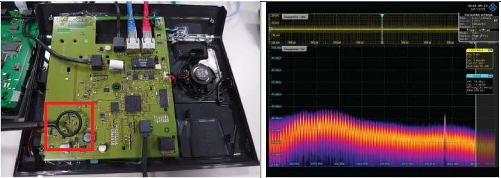
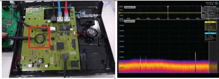
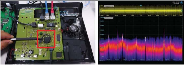
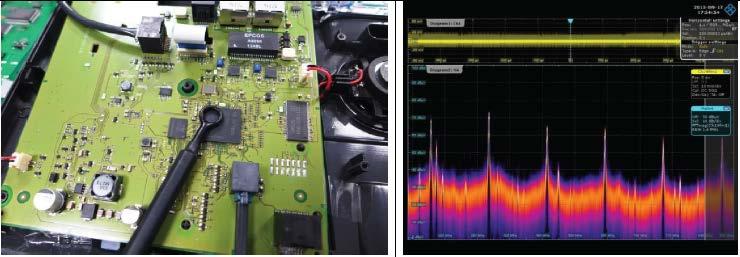
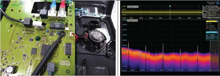
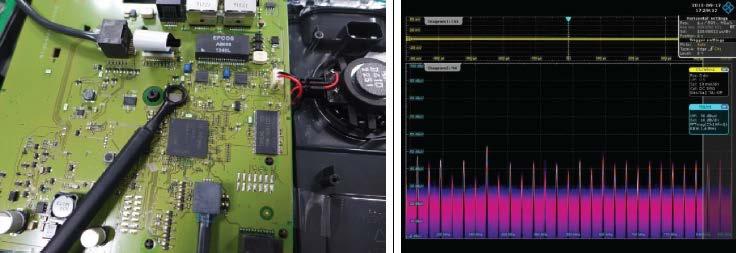
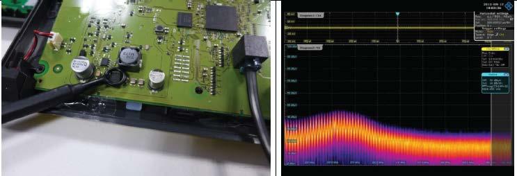
32 Identifying Couping Using Near Fied Probes 32

33 Correating Time and Frequency Domains 33
34 Debugging EMI Using a Digita Oscioscope Summary ı The modern oscioscope with hardware DDC and overapping FFT is capabe of far more than a traditiona oscioscope ı EMI Debugging with an Oscioscope enabes correation of interfering signas with time domain whie maintaining very fast and ivey update rate. ı The combination of synchronized time and frequency domain anaysis with advanced triggers aows engineers to gain insight on EMI probems to isoate and converge the soution quicky. ı Power Suppy design choices have a arge impact on EMI emissions, frequency and time techniques can hep unrave the mystery. 34
Debugging EMI Using a Digital Oscilloscope. Dave Rishavy Product Manager - Oscilloscopes
 Debugging EMI Using a Digital Oscilloscope Dave Rishavy Product Manager - Oscilloscopes 06/2009 Nov 2010 Fundamentals Scope Seminar of DSOs Signal Fidelity 1 1 1 Debugging EMI Using a Digital Oscilloscope
Rohde & Schwarz EMI/EMC debugging with modern oscilloscope. Ing. Leonardo Nanetti Rohde&Schwarz
 Rohde & Schwarz EMI/EMC debugging with modern oscilloscope Ing. Leonardo Nanetti Rohde&Schwarz EMI debugging Agenda l The basics l l l l The idea of EMI debugging How is it done? Application example What
Pulsed RF Signals & Frequency Hoppers Using Real Time Spectrum Analysis
 Pused RF Signas & Frequency Hoppers Using Rea Time Spectrum Anaysis 1 James Berry Rohde & Schwarz Pused Rea Time and Anaysis Frequency Seminar Hopper Agenda Pused Signas & Frequency Hoppers Characteristics
Powerfully simple event analysis software
 synchrowave Event Software Powerfuy simpe event anaysis software Diagnose reay behavior during a power system faut. Time-aign event reports from mutipe reays for comparison and anaysis. Create custom cacuations,
Handheld Cable & Antenna Analyzer R&S ZVH Product Introduction Matthias Roski application engineer
 Handhed Cabe & Antenna Anayzer R&S ZVH Product Introduction Matthias Roski appication engineer Handhed Cabe & Antenna Anayzer R&S ZVH Appication Area Antenna and Cabe Instaation of Transmitter Stations
Time-domain Techniques in EMI Measuring Receivers. Technical and Standardization Requirements
 Time-domain Techniques in EMI Measuring Receivers Technica and Standardization Requirements CISPR = Huge, Sow, Compex, CISPR = Internationa Specia Committee on Radio Interference Technica committee within
Inductors. An inductor, is an electrical component which resists changes in electric current passing through it.
 Inductors An inductor, is an eectrica component which resists changes in eectric current passing through it. It consists of a conductor such as a wire, usuay wound into a coi. When a current fows through
From Digital to RF Debugging in the Time and Frequency Domain. Embedded Systems Conference 2015 May 6-7, 2015
 From Digital to RF Debugging in the Time and Frequency Domain Embedded Systems Conference 2015 May 6-7, 2015 Agenda In this seminar we ll discuss ı The challenges of debugging mixed domain embedded systems
Series. Quite simply, the best in insulation! C.A 6521 C.A 6523 C.A 6525 C.A 6531 C.A Megohmmeters
 Quite simpy, the best in insuation! Series C.A 6521 C.A 6523 C.A 6525 C.A 6531 C.A 6533 Megohmmeters Twin digita-anaogue dispay Giant back-it screen Battery powered for hours Programmabe threshod aarms
Design and Fabrication of a Radiation-Hard 500-MHz Digitizer Using Deep Submicron Technology
 Design and Fabrication of a Radiation-Hard 500-MHz Digitizer Using Deep Submicron Technoogy K.K. Gan The Ohio State University January 10, 2004 K.K. Gan, M.O. Johnson, R.D. Kass, A. Rahimi, C. Rush The
Understanding The HA2500 Horizontal Output Load Test
 Understanding The HA2500 Horizonta Output Load Test Horizonta output stages are part of every CRT video dispay incuding cosed circuit monitors, computer monitors, video games, medica monitors, TVs. HDTVs,
DESIGN OF A DIPOLE ANTENNA USING COMPUTER SIMULATION
 Undergraduate Research Opportunity Project (UROP ) DESIGN OF A DIPOLE ANTENNA USING COMPUTER SIMULATION Student: Nguyen, Tran Thanh Binh Schoo of Eectrica & Eectronic Engineering Nayang Technoogica University
Why/When I need a Spectrum Analyzer. Jan 12, 2017
 Why/When I need a Jan 12, 2017 Common Questions What s the difference of Oscilloscope and Spectrum Analysis Almost all Oscilloscope has FFT for a spectrum view, why I need a spectrum analyzer? When shall
LTC Linear Phase 8th Order Lowpass Filter FEATURES APPLICATIONS DESCRIPTION TYPICAL APPLICATION
 LTC69-7 Linear Phase 8th Order Lowpass Fiter FEATURES n 8th Order, Linear Phase Fiter in SO-8 Package n Raised Cosine Ampitude Response n 43 Attenuation at 2 f CUTOFF n Wideband Noise: 4μV RMS n Operates
Multi-Signal, Multi-Format Analysis With Agilent VSA Software
 Multi-Signal, Multi-Format Analysis With Agilent 89600 VSA Software Ken Voelker Agilent Technologies Inc. April 2012 1 April, 25 2012 Agenda Introduction: New Measurement Challenges Multi-Measurements
RED LION CONTROLS MODEL IFMA - DIN-RAIL FREQUENCY TO ANALOG CONVERTER
 RED LION CONTROLS INTERNATIONAL HEADQUARTERS EUROPEAN HEADQUARTERS 20 Wiow Springs Circe, York, Pa. 17402, (717) 767-6511 FAX: (717) 764-0839 892 Pymouth Road, Sough, Berkshire SL1 4LP Web site- http://www.redion-contros.com
\[7 BROADS, ANTENI 2-6 Mt-
 E.ECTRONCS TECHNCAN 3 & 2 VOL. 1 to each antenna couper (1) a.c. to operate the cooing fans which remove the heat generated during operation and (2) d.c. to operate the contro and protective circuits.
SURGE ARRESTERS FOR CABLE SHEATH PREVENTING POWER LOSSES IN M.V. NETWORKS
 SURGE ARRESTERS FOR CABLE SHEATH PREVENTING POWER LOSSES IN M.V. NETWORKS A. Heiß Energie-AG (EAM), Kasse G. Bazer Darmstadt University of Technoogy O. Schmitt ABB Caor Emag Schatanagen, Mannheim B. Richter
Characteristics of a Novel Slow-Wave Defected Ground Structure for Planar Wideband Filters
 2011 Internationa Conference on Information and Eectronics Engineering IPCSIT vo.6 (2011) (2011) IACSIT Press, Singapore Characteristics of a Nove So-Wave Defected Ground Structure for Panar Wideband Fiters
Essential Capabilities of EMI Receivers. Application Note
 Essential Capabilities of EMI Receivers Application Note Contents Introduction... 3 CISPR 16-1-1 Compliance... 3 MIL-STD-461 Compliance... 4 Important features not required by CISPR 16-1-1 or MIL-STD-461...
Hari The Universal Electrical Interface
 Hari The Universa Eectrica Interface Contributing Companies*: Agient, AMCC, Broadcom, Brocade, Giga, Extreme Network, Gadzoox, IBM, LSI, Picoight, Sun Microsystems, Vitesse Ai Ghiasi (650)786-3310 ghiasi@eng.sun.com
EM330 Installation and use instructions Three-phase energy analyzer for indirect connection (5A) with Modbus, pulse or M-Bus interface
 with Modbus, pulse or M-Bus interface") EM330 Instaation and use instructions Three-phase energy anayzer for indirect connection (5A) with Modbus, puse or M-Bus interface Code 8021422 Genera warnings HAZARD: Live parts. Heart attack, burns and
EM330 Instaation and use instructions Three-phase energy anayzer for indirect connection (5A) with Modbus, puse or M-Bus interface Code 8021422 Genera warnings HAZARD: Live parts. Heart attack, burns and
BVRIT HYDERABAD College of Engineering for Women Department of Electronics and Communication Engineering
 Subject Name: BVRIT HYDERABAD Coege of Engineering for Women Department of Eectronics and Communication Engineering Prepared by (Facuty Name): Hand Out Eectronic Circuit Anaysis Mr. G. Siva SankarVarma,
Provides exact fault location to one span
 TWS Mark VI Traveing wave faut ocator Provides exact faut ocation to one span Reduce down time by getting to the faut site faster Track intermittent sef cearing fauts and focus maintenance at the right
RF Measurements You Didn't Know Your Oscilloscope Could Make
 RF Measurements You Didn't Know Your Oscilloscope Could Make January 21, 2015 Brad Frieden Product Manager Keysight Technologies Agenda RF Measurements using an oscilloscope (30 min) When to use an Oscilloscope
Keysight Technologies Essential Capabilities of EMI Receivers. Application Note
 Keysight Technologies Essential Capabilities of EMI Receivers Application Note Contents Introduction... 3 CISPR 16-1-1 Compliance... 3 MIL-STD-461 Compliance... 4 Important features not required by CISPR
Communication Systems
 Communication Systems 1. A basic communication system consists of (1) receiver () information source (3) user of information (4) transmitter (5) channe Choose the correct sequence in which these are arranged
Understanding Probability of Intercept for Intermittent Signals
 2013 Understanding Probability of Intercept for Intermittent Signals Richard Overdorf & Rob Bordow Agilent Technologies Agenda Use Cases and Signals Time domain vs. Frequency Domain Probability of Intercept
LT6658 Precision Dual Output, High Current, Low Noise, Voltage Reference. Applications. Typical Application
 Features Dua Output Tracking Reference Each Output Configurabe to 6 Output : ma Source/2mA Sink Output 2: ma Source/2mA Sink Low Drift: A-Grade: ppm/ C Max B-Grade: 2ppm/ C Max High Accuracy: A-Grade:
NX5 SERIES. Compact Multi-voltage Photoelectric Sensor Power Supply Built-in. Multi-voltage photoelectric sensor usable worldwide.
 7 Compact Muti-votage Photoeectric SERIES Reated Information Genera terms and conditions... F-17 Gossary of terms / Genera precautions...p.139~ / P.1 seection guide... P.23~ China s CCC mark... P.19 PHOTO
Electronic circuit protector ESX10-Sxxx-DC24V-1A-10A
 Eectronic circuit protector ESX10-Sxxx-DC2V-1A-10A Description The mode ESX10-Sxxx extends our product group of eectronic overcurrent protection devices for DC 2 V appications. At a width of ony 12.5mm
ThermaData Logger DATA-LOGGERS. temperature recording thermometers.
 ThermaData Logger temperature recording thermometers waterproof housing offering IP66/67 protection temperature range or 125 C resoution 0.1 C, high accuracy ±0.5 C meets EN 12830, S & T, C & D, 1 The
An Introduction to EMC Testing (what can be done with scopes) Vincent Lascoste EMC Product Manager - RSF
 Vincent Lascoste EMC Product Manager - RSF") An Introduction to EMC Testing (what can be done with scopes) Vincent Lascoste EMC Product Manager - RSF Definition of ElectroMagnetic Compatibility (EMC) EMC is defined as: "The ability of devices and
An Introduction to EMC Testing (what can be done with scopes) Vincent Lascoste EMC Product Manager - RSF Definition of ElectroMagnetic Compatibility (EMC) EMC is defined as: "The ability of devices and
TETRA Tx Test Solution
 Product Introduction TETRA Tx Test Solution Signal Analyzer Reference Specifications ETSI EN 300 394-1 V3.3.1(2015-04) / Part1: Radio ETSI TS 100 392-2 V3.6.1(2013-05) / Part2: Air Interface May. 2016
Fast Ferrite ICRF Matching System in Alcator C-Mod*
 Poster QP-00053, 48 th APS-DPP Annua Meeting, Phiadephia, PA, 006 Fast Ferrite ICRF Matching System in Acator C-Mod*. Lin, A. Binus, A. Parisot, S. Wukitch and the Acator C-Mod team MIT, Pasma Science
Homework Assignment # 9 (Due April 6, 8am)
") EE143 Homework Assignment # 9 (Due Apri 6, 8am) S2006 Week of 3/27 is Spring Recess Midterm Exam #2 wi be on Apri 5 (Wed) 6:00-7:30pm, GPB Room 100, cosed book exam, 8 sheets of handwritten notes aowed.
EE143 Homework Assignment # 9 (Due Apri 6, 8am) S2006 Week of 3/27 is Spring Recess Midterm Exam #2 wi be on Apri 5 (Wed) 6:00-7:30pm, GPB Room 100, cosed book exam, 8 sheets of handwritten notes aowed.
LT1630/LT MHz, 10V/µs, Dual/Quad Rail-to-Rail Input and Output Precision Op Amps. Applications. Typical Application
 Features n Gain-Bandwidth Product: 3MHz n Sew Rate: V/µs n Low Suppy Current per Ampifier: 3.5mA n Input Common Mode Range Incudes Both Rais n Output Swings Rai-to-Rai n Input Offset Votage, Rai-to-Rai:
Measurement Techniques
 Measurement Techniques Primary measurement tool: Oscilloscope Other lab tools: Logic Analyser, Gain-Phase Analyser, Spectrum Analyser Visualisation of electrical signals in the time domain Visualisation
R is in the unit of ma/mw or A/W. For semiconductor detectors, the value is approximately, 0.5 ma/mw.
 Light Detection Conventiona methods for the detection of ight can be categorized into photo-synthesis, photographic pate, and photoeectric effect. Photo-synthesis and photographic pate are based on ight-induced
User's Manual. VHF Wireless Microphone System. Guangdong Takstar Electronic Co., Ltd.
 User's Manua VHF Wireess Microphone System Guangdong Takstar Eectronic Co, Ltd Business Centre of Domestic Saes: Te: 020-86381808 / 86381888 Fax: 020-86599478 Production Base: Bocady Industria Viage, Longqiao
Measurement of Digital Transmission Systems Operating under Section March 23, 2005
 Measurement of Digital Transmission Systems Operating under Section 15.247 March 23, 2005 Section 15.403(f) Digital Modulation Digital modulation is required for Digital Transmission Systems (DTS). Digital
Implementation of PV and PIV Control for Position Control of Servo Motor
 IJSRD - Internationa Journa for Scientific Research & Deveopment Vo. 5, Issue 1, 2017 ISSN (onine): 2321-0613 Impementation of PV and PIV Contro for Position Contro of Servo Motor J.Priya 1 R.Rambrintha
Georgia Institute of Technology. simulating the performance of a 32-bit interconnect bus. referenced to non-ideal planes. A transient simulation
 Power ntegrity/signa ntegrity Co-Simuation for Fast Design Cosure Krishna Srinivasan1, Rohan Mandrekar2, Ege Engin3 and Madhavan Swaminathan4 Georgia nstitute of Technoogy 85 5th St NW, Atanta GA 30308
NGRM700. Neutral Grounding Resistor Monitor
 M700 eutra Grounding Resistor Monitor M700_D00292_02_D_XXE/07.2018 M700 eutra Grounding Resistor Monitor Product description The M700 is ony intended for use in high-resistance grounded systems. In these
Multi-stage Amplifiers Prof. Ali M. Niknejad Prof. Rikky Muller
 EECS 105 Spring 2017, Modue 4 Muti-stage Ampifiers Prof. Ai M. Niknejad Department of EECS Announcements HW10 due on Friday Lab 5 due this week 2 weeks of ecture eft! 2 Mutistage Ampifiers Why cascade
Utilizzo del Time Domain per misure EMI
 Utilizzo del Time Domain per misure EMI Roberto Sacchi Measurement Expert Manager - Europe 7 Giugno 2017 Compliance EMI receiver requirements (CISPR 16-1-1 ) range 9 khz - 18 GHz: A normal +/- 2 db absolute
LIGHTNING PROTECTION OF MEDIUM VOLTAGE OVERHEAD LINES WITH COVERED CONDUCTORS BY ANTENNA-TYPE LONG FLASHOVER ARRESTERS
 C I R E D 17 th Internationa Conference on Eectricity Distribution Barceona, 12-15 May 23 LIGHTNING PROTECTION OF MEDIUM VOLTAGE OVERHEAD LINES WITH COVERED CONDUCTORS BY ANTENNA-TYPE LONG FLASHOVER ARRESTERS
OpenStax-CNX module: m Inductance. OpenStax College. Abstract
 OpenStax-CNX modue: m42420 1 Inductance OpenStax Coege This work is produced by OpenStax-CNX and icensed under the Creative Commons Attribution License 3.0 Cacuate the inductance of an inductor. Cacuate
CruzPro FU60. Intelligent Digital Fuel Gauge/w Alarms & Consumption Calculator
 Other CruzPro Products Depthsounders & Speed/Temperature/Logs PC Based Fishfinders and Active Depth Transducers DC Vots/Amps/Amp-Hour Monitor AC Vots/Amps/Freq/kW Monitor LPG/Petro Gas Detectors/Aarms
The Value of Pre-Selection in EMC Testing. Scott Niemiec Application Engineer
 The Value of Pre-Selection in EMC Testing Scott Niemiec Application Engineer Video Demonstrating Benefit of Pre-selection 400MHz -1GHz Sweep with RBW = 120kHz Yellow: w/ preselection Green: w/o pre-selection
Series 700A Power Processor
 Series 700A Power Processor 5 25 SINGLE PHASE 10 500 THREE PHASE VOLTAGE REGULATION, ISOLATION, AND POWER DISTRIBUTION FOR CLEAN, SPIKE-FREE, STABLE VOLTAGE When Power Quaity Is A Must And Faiure Is Not
EMI Test Receivers: Past, Present and Future
 EM Test Receivers: Past, Present and Future Andy Coombes EMC Product Manager Rohde & Schwarz UK Ltd 9 th November 2016 ntroduction ı Andy Coombes EMC Product Manager ı 20 years experience in the field
3250 Series Spectrum Analyzer
 The most important thing we build is trust ADVANCED ELECTRONIC SOLUTIONS AVIATION SERVICES COMMUNICATIONS AND CONNECTIVITY MISSION SYSTEMS 3250 Series Spectrum Analyzer > Agenda Introduction
A CPW-Fed Printed Monopole Ultra-Wideband Antenna with E-Shaped Notched Band Slot
 Iraqi Journa of Appied Physics Emad S. Ahmed Department of Eectrica and Eectronic Engineering University of Technoogy, Baghdad, Iraq A CPW-Fed Printed Monopoe Utra-Wideband Antenna with E-Shaped Notched
A2000 Multifunctional Power Meter
 A2 3-348-98-3 16/2.8 Measurement of current, votage, active, reactive and apparent power, power factor, active and reactive energy, harmonic distortion and harmonics Precision measured vaues with error
Understanding New Pulse-analysis Techniques
 Understanding New Pulse-analysis Techniques Giuseppe Savoia Keysight Technologies Aerospace Defense Symposium Agenda Concept for Radar/Pulse signal analysis AD Symposium Page 2 Vector signal analyzers
LT1498/LT MHz, 6V/µs, Dual/Quad Rail-to-Rail Input and Output Precision C-Load Op Amps FEATURES DESCRIPTION APPLICATIONS
 FEATURES n Rai-to-Rai Input and Output n 475 Max V OS from V + to V n Gain-Bandwidth Product: MHz n Sew Rate: 6V/μs n Low Suppy Current per Ampifi er: 1.7mA n Input Offset Current: 65 Max n Input Bias
LTC4365 UV, OV and Reverse Supply Protection Controller APPLICATIONS TYPICAL APPLICATION
 , and Reverse Suppy Protection Controer FEATURES n Wide Operating Votage Range: 2.5V to 34V n Overvotage Protection to 6V n Reverse Suppy Protection to 4V n Bocks 5Hz and 6Hz AC Power n No Input Capacitor
P a g e 1 ST985. TDR Cable Analyzer Instruction Manual. Analog Arts Inc.
 P a g e 1 ST985 TDR Cable Analyzer Instruction Manual Analog Arts Inc. www.analogarts.com P a g e 2 Contents Software Installation... 4 Specifications... 4 Handling Precautions... 4 Operation Instruction...
Dive deep into interference analysis
 Dive deep into interference analysis Dive deep into interference analysis Contents 1. Introducing Narda Outstanding features 2. Basics IDA 2 3. IDA 2 presentation How IDA 2 is used: 1) Detect 2) Analyze
An Efficient Adaptive Filtering for CFA Demosaicking
 Dev.. Newin et. a. / (IJCSE) Internationa Journa on Computer Science and Engineering An Efficient Adaptive Fitering for CFA Demosaicking Dev.. Newin*, Ewin Chandra Monie** * Vice Principa & Head Dept.
Rectangular-shaped Inductive Proximity Sensor. website
 785 Rectanguar-shaped Inductive Proximity Sensor SERIES Reated Information Genera terms and conditions... F-3 Gossary of terms... P.157~ guide... P.781~ Genera precautions... P.1579~ PHOTO PHOTO IGHT FOW
Spectrum Analyzers 2680 Series Features & benefits
 Data Sheet Features & benefits n Frequency range: 9 khz to 2.1 or 3.2 GHz n High Sensitivity -161 dbm/hz displayed average noise level (DANL) n Low phase noise of -98 dbc/hz @ 10 khz offset n Low level
Improving the Active Power Filter Performance with a Prediction Based Reference Generation
 Improving the Active Power Fiter Performance with a Prediction Based Reference Generation M. Routimo, M. Sao and H. Tuusa Abstract In this paper a current reference generation method for a votage source
Electronic Circuit Protector ESX10-T.-DC 24 V
 Eectronic Circuit Protector ESX0-T.-DC 2 V Description The mode ESX0-T extends our product group of eectronic overcurrent protection devices for DC 2 V appications. At a width of ony 2.5 mm it provides
Introduction: The FFT emission measurement method
 Introduction: The FFT emission measurement method Tim Williams Elmac Services C o n s u l t a n c y a n d t r a i n i n g i n e l e c t r o m a g n e t i c c o m p a t i b i l i t y Wareham, Dorset, UK
Wireless Communications
 Wireess Communications Ceuar Concept Hamid Bahrami Reference: Rappaport Chap3 Eectrica & Computer Engineering Statements of Probems Soving the probem of Spectra congestion System Capacity A system-eve
Wirelessly Wonderful. Solutions for IoT test challenges. Alessandro Salsano Key Account Manager A&D 5/26/2017
 Wirelessly Wonderful Solutions for IoT test challenges Alessandro Salsano Key Account Manager A&D 5/26/2017 Agenda Major IoT Design and test challenges 1. Maximizing your device s battery life 2. Debug
INTERNATIONAL TELECOMMUNICATION UNION 02/4%#4)/.!'!).34 ).4%2&%2%.#%
/.!'!).34 ).4%2&%2%.#%") INTERNATIONAL TELECOMMUNICATION UNION )454 TELECOMMUNICATION STANDARDIZATION SECTOR OF ITU 02/4%#4)/!'!)34 )4%2&%2%#% #!,#5,!4)/ /& 6/,4!'% )$5#%$ )4/ 4%,%#/--5)#!4)/,)%3 &2/- 2!$)/ 34!4)/ "2/!$#!343!$
INTERNATIONAL TELECOMMUNICATION UNION )454 TELECOMMUNICATION STANDARDIZATION SECTOR OF ITU 02/4%#4)/!'!)34 )4%2&%2%#% #!,#5,!4)/ /& 6/,4!'% )$5#%$ )4/ 4%,%#/--5)#!4)/,)%3 &2/- 2!$)/ 34!4)/ "2/!$#!343!$
Federal Communications Commission Office of Engineering and Technology Laboratory Division
 April 9, 2013 Federal Communications Commission Office of Engineering and Technology Laboratory Division Guidance for Performing Compliance Measurements on Digital Transmission Systems (DTS) Operating
ISOSCAN EDS440/441. Device variants. Alarm messages are directly indicated on the device display
 EDS/ Insuation faut ocators for ocaisation of insuation fauts in unearthed DC, AC and three-phase power suppy systems (IT systems) EDSxx_D D_XXEN/. EDS/ Insuation faut ocators for ocaisation of insuation
UNIVERSITY OF CALIFORNIA College of Engineering Department of Electrical Engineering and Computer Sciences. EE143 Final Exam
 UNIVERSITY OF CALIFORNIA Coege of Engineering Department of Eectrica Engineering and Computer Sciences Spring 2006 EE143 Fina Exam Famiy Name First name SID Signature Sampe Soutions Instructions: DO ALL
EMI 相容性測試 預相容性測試及量測法規
 EMI 相容性測試 預相容性測試及量測法規 12/13/2016 太克科技 Laurance Yeh 葉志豪 chi-hao.yeh@tektronix.com Agenda EMI introduction EMI pre-compliance and debugging tools RSA306B demo MDO4000C demo lab 13 December 2016 Agenda EMI
WS2812 Intelligent control LED integrated light source
 Features and Benefits Contro circuit and RGB chip are integrated in a package of 5050 components, form a compete contro of pixe point. Buit-in signa reshaping circuit, after wave reshaping to the next
Log Periodic Dipole Array Antenna
 Features MHz to 1 GHz frequency range Antennas Moderate gain for maximum iumination area Low VSWR of ess than 2:1 minimizes mismatch osses between ampifier and antenna 2 kw continuous RF input power (Maximum)
ISOSCAN EDS440/441. Device variants. Alarm messages are directly indicated on the device display
 EDS/ Insuation faut ocators for ocaisation of insuation fauts in unearthed DC, AC and three-phase power suppy systems (IT systems) EDS-_D D_XXEN/. EDS/ Insuation faut ocators for ocaisation of insuation
A Specialized Software Package Useful In The Analysis Of The Harmonic Current Flow In Networks With Large Power Static Converters
 SEECE OPICS in MHEMIC MEHOS and COMPUION ECHNIQUES in EECRIC ENGINEERING Speciaized Software Package Usefu In he naysis Of he Haronic Current Fow In Networks With arge Power Static Converters VIORE VRVR,
EET 223 RF COMMUNICATIONS LABORATORY EXPERIMENTS
 EET 223 RF COMMUNICATIONS LABORATORY EXPERIMENTS Experimental Goals A good technician needs to make accurate measurements, keep good records and know the proper usage and limitations of the instruments
SiTime University Turbo Seminar Series
 SiTime University Turbo Seminar Series How to Measure Clock Jitter Part I Principle and Practice April 8-9, 2013 Agenda Jitter definitions and terminology Who cares about jitter How to measure clock jitter
General terms and conditions... F-7 Glossary of terms / General precautions... P.1455~ / P panasonic.net/id/pidsx/global
 9 Digita Sensor FX- SERIES Reated Information Genera terms and conditions... F-7 Gossary of terms / Genera precautions... P.455~ / P.5 Sensor seection guide... P.3~ seection... P.5~ PHOTO PHOTO IGHT FOW
NETWORK ANALYSER MPR-50 / MPR-52S / MPR-60S / MPR-63
 ETWOR AAYSER MPR-50 / MPR-52S / MPR-60S / Modbus / Ethernet Gateway Genera MPR-50 : etwor Anayser. MPR-52S : etwor Anayser with THD measurement, R S-45 (MODBUS) and Aarm Contact. MPR-60S: etwor Anayser
Reference Sources. Prelab. Proakis chapter 7.4.1, equations to as attached
 Purpose The purpose of the lab is to demonstrate the signal analysis capabilities of Matlab. The oscilloscope will be used as an A/D converter to capture several signals we have examined in previous labs.
MicroDS The motion solution INSTALLATION and USER S GUIDE Revision B June 12
 MicroDS The motion soution INSTALLATION and USER S GUIDE Revision B June 12 CONTENTS & INTRODUCTION MicroDS User's Manua Revision Date Description Updated Pages A June 2003 C27159-001 B June 2012 MicroDS
SINEAX CAM Universal measuring unit for heavy current variables
 SIEAX CAM niversa measuring unit for heavy current variabes Main features Consistent measurement (without interruption) Suitabe for strongy distorted networs, zero crossing or phase ange contros I/O interface
ELECTRICAL MEASURING INSTRUMENTS PROGRAMME
 ENERGY SECTOR EECTRICA MEASURING INSTRUMENTS PROGRAMME Index INDEX MEASURING CENTRES Page imc 7/ MC 7 - Advanced Power Quaity Anayser... MC 77 - Power Quaity Anaizer... MC 76 - Networ Anayzer... MC 7 -
Getting the most out of your Measurements Workshop. Mike Schnecker
 Getting the most out of your Measurements Workshop Mike Schnecker Agenda Oscilloscope Basics Using a RTE1000 Series Oscilloscope. Probing Basics Passive probe compensation Ground lead effects Vertical
RF Fundamentals Part 2 Spectral Analysis
 Spectral Analysis Dec 8, 2016 Kevin Nguyen Keysight Technologies Agenda Overview Theory of Operation Traditional Spectrum Analyzers Modern Signal Analyzers Specifications Features Wrap-up Page 2 Overview
PEP - II LFB - Status and Predictions
 PEP - II LFB - Status and Predictions Measurements and observations from o/30 and 10/31 high-current operation at 2.2A Predictions and impications for upgraded high-current configurations J. Fox, S. Prabhakar,
Troubleshooting Common EMI Problems
 By William D. Kimmel, PE Kimmel Gerke Associates, Ltd. Learn best practices for troubleshooting common EMI problems in today's digital designs. Industry expert William Kimmel of Kimmel Gerke Associates
Energy Measurement and Management MT MD Multifunction meters with load profile
 Energy Measurement and Management MT851... MD851... Mutifunction meters with oad profie The MT851 / MD851 eectronic mutifunction eectricity meters are designed for metering of active energy in two directions,
Radiation-Hard Optical Link in the ATLAS Pixel Detector
 Radiation-Hard Optica Link in the ATLAS Pixe Detector K.K. Gan The Ohio State University August 18, 2004 K.E. Arms, K.K. Gan, M. Johnson, H. Kagan, R. Kass, A. Rahimi, C. Rush, S. Smith, R. Ter-Antonian,
LTC6957-1/LTC6957-2/ LTC6957-3/LTC Low Phase Noise, Dual Output Buffer/Driver/ Logic Converter APPLICATIONS TYPICAL APPLICATION
 FEATURES Low Phase Noise Buffer/Driver Optimized Conversion of Sine Wave Signas to Logic Leves Three Logic Output Types Avaiabe LVPECL LVDS CMOS Additive Jitter 45fs RMS (LTC6957-1) Frequency Range Up
Understanding and Optimizing Electromagnetic Compatibility in Switchmode Power Supplies
 Understanding and Optimizing Electromagnetic Compatibility in Switchmode Power Supplies 1 Definitions EMI = Electro Magnetic Interference EMC = Electro Magnetic Compatibility (No EMI) Three Components
WIFI-BASED IMAGING FOR GPR APPLICATIONS: FUNDAMENTAL STUDY AND EXPERIMENTAL RESULTS
 WIFI-BASED IMAGING FOR GPR APPICATIONS: FUNDAMENTA STUDY AND EXPERIMENTA RESUTS Weike Feng *, Jean-Miche Friedt, Zhipeng Hu 3, Grigory Cherniak, and Motoyuki Sato 4 Graduate Schoo of Environmenta Studies,
R3477. Ideal for mobile communication applications including base stations and handsets, from the development stage to production and installation
 R3477 Signal Analyzers Ideal for mobile communication applications including base stations and handsets, from the development stage to production and installation Frequency range: 9 khz to 13.5 GHz World
Rectangular-shaped Inductive Proximity Sensor.
 71 PHOTOEECTRIC PHOTOEECTRIC IGHT FOW PARTICUAR USE SIMPE MEASUREMENT STATIC CONTRO Rectanguar-shaped Inductive Proximity Sensor SERIES Reated Information Genera terms and conditions... F-17 Gossary of
10GBASE-T Transmitter SNDR Definition (System ID Approach) IEEE P802.3an Task Force Santa Clara, Feb 2005 Albert Vareljian, Hiroshi Takatori KeyEye
 IEEE P802.3an Task Force Santa Clara, Feb 2005 Albert Vareljian, Hiroshi Takatori KeyEye") 10GBASE-T Transmitter SNDR Definition (System ID Approach) IEEE P802.3an Task Force Santa Clara, Feb 2005 Albert Vareljian, Hiroshi Takatori KeyEye 1 OUTLINE Transmitter Performance Evaluation Block Diagram
10GBASE-T Transmitter SNDR Definition (System ID Approach) IEEE P802.3an Task Force Santa Clara, Feb 2005 Albert Vareljian, Hiroshi Takatori KeyEye 1 OUTLINE Transmitter Performance Evaluation Block Diagram
Description Absolute Maximum Ratings Parameter Max. Units Thermal Resistance Parameter Typ. Max. Units
 Logic-Leve Gate Drive dvanced Process Technoogy Isoated Package High Votage Isoation = 2.5KVRMS Sink to Lead Creepage Dist. = 4.8mm Fuy vaanche Rated Lead-Free Description Fifth Generation HEXFETs from
EMC Pulse Measurements
 EMC Pulse Measurements and Custom Thresholding Presented to the Long Island/NY IEEE Electromagnetic Compatibility and Instrumentation & Measurement Societies - May 13, 2008 Surge ESD EFT Contents EMC measurement
LT Dual Very Low Noise, Differential Amplifi er and 5MHz Lowpass Filter DESCRIPTION FEATURES APPLICATIONS TYPICAL APPLICATION
 FEATURES n Dua Differentia Ampifi er with MHz Lowpass Fiters 4th Order Fiters Approximates Chebyshev Response Guaranteed Phase and Gain Matching Resistor-Programmabe Differentia Gain n >8 Signa-to-Noise