OPTO-ELECTRONIC DEVICES
|
|
|
- Magdalene McCormick
- 6 years ago
- Views:
Transcription

1 SEVENTH SEMESTER OPTO-ELECTRONIC DEVICES COMMUNICATION LAB DEPARTMENT OF ELECTRICAL ENGINEERING Prepared By: Checked By: Approved By: Engr. Zubair Khalid Engr. M.Nasim Khan Dr.Noman Jafri Lecturer (Lab) Electrical, Senior Lab Engineer Electrical, Dean, FUUAST-Islamabad FUUAST-Islamabad FUUAST-Islamabad 1
2 Name: Registration No: Roll No: Semester: Batch: 2
3 CONTENTS Exp No List of Experiments 1 INTRODUCTION TO OPTOELECTRONIC DEVICES 2 INTRODUCTION TO OPTOELECTRONIC DEVICES TRAINER FO FIBRE OPTIC TRANSMITTER THROUGH DIGITAL CIRCUIT 4 ANALOG SIGNAL THROUGH THE OPTICAL FIBER 5 DIGITAL SIGNAL THROUGH THE OPTICAL FIBER 6 OPTICAL FIBER RECEIVER CIRCUIT 7 TO DETERMINE THE NUMERICAL APERTURE OF OPTICAL SIGNAL 8 STUDY THE OPTICAL (E-O) CHARACTERISTICS OF FIBER OPTIC 660nm CONVERTER 9 TRIANGULAR WAVE THROUGH THE OPTICAL FIBER 10 AMPLITUDE MODULATED SIGNAL THROUGH THE OPTICAL FIBER 11 LIGHT DEPENDENT RESISTOR 12 PHOTOVOLTAIC CELL 13 MAKING A LIGHT GUIDE CIRCUIT 14 LOSSES IN OPTICAL FIBER AT 660NM 15 FREQUENCY MODULATED SIGNAL THROUGH THE OPTICAL FIBER 16 LOSSES IN OPTICAL FIBER AT 850NM 3
4 EXPERIMENT NO. 1 INTRODUCTION TO OPTOELECTRONIC DEVICES AIM OF EXPRIMENT The main purpose of this lab is the introduction of different optoelectronic devices, these are those devices which will come across while performing experiments in the lab. 1. LED. 2. PHOTO TRANSISTOR. 3. FIBER OPTICS. 4. FUNCTION GENERATOR. 4
5 5. OSCILLOSCOPE. 6. OMEGA TYPE FO


6 EXPERIMENT NO. 2 INTRODUCTION TO OPTOELECTRONIC DEVICES TRAINER FO-003 6
7 7

8 EXPERIMENT NO. 3 FIBRE OPTIC TRANSMITTER THROUGH DIGITAL CIRCUIT THEORY Transmitter Receiver Optical fiber As you learned in your main course, all fiber optic systems have three major elements: Figure 1 depicts these major elements. The transmitter and receiver contain smaller elements or building blocks, some of which you should recognize from previous activities. So far with the instructions in this manual we have made a light guide, characterized and terminated optical fibers, and evaluated LEDs and detectors. In this activity we shall investigate one of the last two elements in a fiber optic system the driver for the light source eps Figure1 Basic elements in fiber optic links. As you have studied, there are two commonly used light sources in fiber optics, LEDs and laser diodes. The drivers covered in this activity are for visible and infrared LEDs. We will not discuss drivers for laser diodes because they are outside the scope of this manual. They can be very sophisticated, complex, and cost thousands of dollars. There are also optical safety considerations when using laser diodes. In more advanced fiber optics classes, or in your job, you will find the information you learned here about driving LED is a good primer for laser diode driver design. Materials Required Red LED (IF-E96-blue housing-pink dot) 2N3904 Resistor Signal generator Multimeter Oscilloscope Solder less breadboard 8
9 PROCEDURE 1. Calculate the resistor value, Rc, needed to permit a current of 20 ma through the LED in Figure 3 when the transistor is saturated. Assume the Vce(sat)=0.2 volts and the Vf for the LED to be 1.8 volts. 2. Calculate the maximum value of the base resistor, Rb,needed to drive the transistor into saturation if Vi was connected to + 5 volts. Assume Vbe=.7 volts and hfe(min)= Choose resistors from the kit that are closest to the calculated Rc and one-half the calculated Rb. See Table 2 for choices. Figure2 The two states of digital and fiber optic systems. 4. Assemble the circuit shown in Figure 3 on your solderless breadboard. Use the pin diagrams found to identify device connections. 5. Turn on the variable voltage power supply and adjust the output voltage to + 5 volts DC. 6. Connect the end of Rb marked Vi to + 5 volts. The red LED should now be on. If not, check the power supply and electrical connections. 7. With the multimeter measure the transistor collector-to-emitter voltage and the voltage across the LED, then record the results in Table Change Vi from the + 5 volts to ground. The red LED should now be off. Figure3 Single NPN transistor switching circuit for driving a fiber optic LED. 9. With the multimeter, measure the collector-to-emitter voltage across the transistor and record the result in Table 1. 9
10 RESULTS Table 1 Measured data taken from the circuit shown in Figure 8.3. Measurement Vce (LED on) Vf (LED) Vce (LED off) Data Analysis & Questions Is the measured voltage across the collector of 2N3904 transistor in Figure 3 for the LED "on" and "off" compare to what you expected? Why or why not? With the LED "on" in Figure 3 calculate the "on" current using the measured data in this activity for Vce (sat) and Vf. 10
11 EXPERIMENT NO. 4 ANALOG SIGNAL THROUGH THE OPTICAL FIBER Apparatus: Procedure 1. Function Generator 2. Oscilloscope 3. Optical Fiber Trainer OMEGA TYPE FO Optical fiber 1. Generate a analog Signal from the function generator of 2Vpeak to peak with the frequency of 1KHz 2. Apply this analog Signal to the input of the Optical fiber trainer. 3. Fix the optical fiber to transmitter and receiver. 4. Adjust the gain of the system. Its gain should be Take the Output and measure the loss in amplitude of the signal 6. Note the input and output measured values in the table shown below 7. Draw the input and output waveforms of the signals 8. Repeat the above steps by the applying the analog input signal through function generator of 4Vpeak-topeak with the frequency of 2KHz. Figure. Sine Wave 11
12 Results Table Readings at 660nm 1m 100Hz 500Hz 1KHz 1V 2V 3V 4V Table Readings at 850nm 1m 100Hz 500Hz 1KHz 1V 2V 3V 4V WAVE FORMS INPUT WAVE FORM OUTPUT WAVE FORM 12
13 EXPERIMENT NO. 5 DIGITAL SIGNAL THROUGH THE OPTICAL FIBER Apparatus: Procedure 5. Function Generator. 6. Oscilloscope. 7. Optical Fiber Trainer OMEGA TYPE FO Optical fiber. 9. Generate a Digital Signal from the function generator of 2Vpeak to peak with the frequency of 1KHz 10. Apply this Digital Signal to the input of the Optical fiber trainer. 11. Fix the optical fiber to transmitter and receiver. 12. Adjust the gain of the system. Its gain should be Take the Output and measure the loss in amplitude of the signal 14. Note the input and output measured values in the table shown below 15. Draw the input and output waveforms of the signals 16. Repeat the above steps by the applying the Digital input signal through function generator of 4Vpeak-topeak with the frequency of 2 KHz. 13
14 Results: Table Readings at 660nm 5m 100Hz 500Hz 1KHz 1V 2V 3V 4V Table Readings at 850 nm 5m 100Hz 500Hz 1KHz 1V 2V 3V 4V WAVE FORMS INPUT WAVE FORM OUTPUT WAVEFORM 14
15 EXPERIMENT NO. 6 OPTICAL FIBER RECEIVER CIRCUIT Equipment Required Procedure 1. Photo Transistor 2. Resistors 3. LED 4. Power Supply 5. Multimeter 6. Solder less Bread board 7. Connecting wires 1. Connect the circuit as shown in the diagram given below 2. Apply +5V potential to the collector and emitter should be grounded 3. There should be no input at the base. Do remember that base should always be kept open. 4. Measure the current properly at the emitter. 5. When we apply the light at the base of transistor the current flows through the emitter resulting in glowing the LED. 6. Measure the voltage across the Resistor when the light is applied to the phototransistor and when it is kept OFF. 7. Measure the current across the Resistor when the light is applied to the phototransistor and when it is kept OFF. Figure 1 Optical Fiber Receiver Circuit 15
16 Results V cc I C I E V RC Light ON Light OFF 16
17 EXPERIMENT NO. 7 TO DETERMINE THE NUMERICAL APERTURE OF OPTICAL SIGNAL 17
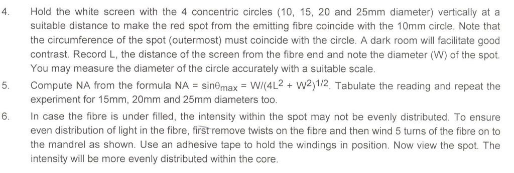
18 18
19 EXPERIMENT NO. 8 STUDY THE OPTICAL (E-O) CHARACTERISTICS OF FIBER OPTIC 660nm CONVERTER 19
20 20
21 EXPERIMENT NO. 9 TRIANGULAR WAVE THROUGH THE OPTICAL FIBER Apparatus: 1. Communication system trainer KL-100 / ED Oscilloscope. 3. Optical Fiber Trainer OMEGA TYPE FO Optical fiber. Procedure 1. Generate a Triangular Signal from the communication system trainer. 2. Apply this Triangular Signal to the input of the Optical fiber trainer. 3. Fix the optical fiber to transmitter and receiver. 4. Adjust the gain of the system. Its gain should be Take the Output and measure the loss in amplitude of the signal 6. Note the input and output measured values in the table shown below 7. Draw the input and output waveforms of the signals 8. Repeat the above steps by the applying the Triangular input signal through communication system trainer at other carrier amplitudes. Figure. Triangular Wave 21
22 Results: Table Readings at 660nm 5m 100Hz 500Hz 1KHz 1V 2V 3V 4V Table Readings at 850 nm 5m 100Hz 500Hz 1KHz 1V 2V 3V 4V WAVE FORMS INPUT WAVE FORM OUTPUT WAVEFORM 22
23 EXPERIMENT NO. 10 AMPLITUDE MODULATED SIGNAL THROUGH THE OPTICAL FIBER Apparatus: Procedure 9. Communication system trainer KL-100 / ED Oscilloscope. 11. Optical Fiber Trainer OMEGA TYPE FO Optical fiber. 17. Generate a AM Signal from the communication system trainer. 18. Apply this AM Signal to the input of the Optical fiber trainer. 19. Fix the optical fiber to transmitter and receiver. 20. Adjust the gain of the system. Its gain should be Take the Output and measure the loss in amplitude of the signal 22. Note the input and output measured values in the table shown below 23. Draw the input and output waveforms of the signals 24. Repeat the above steps by the applying the AM input signal through communication system trainer at other carrier amplitudes. Figure Amplitude Modulated Signal Results: Voltage Power Voltage Power Input Output 23
24 EXPERIMENT NO. 11 LIGHT DEPENDENT RESISTOR The light-sensitive part of the LDR is a wavy track of cadmium sulphide. Light energy triggers the release of extra charge carriers in this material, so that its resistance falls as the level of illumination increases. A Photoresistor is made of a high resistance semiconductor. If light falling on the device is of high enough frequency, photons absorbed by the semiconductor give bound electrons enough energy to jump into the conduction band. The resulting free electron (and its hole partner) conduct electricity, thereby lowering resistance. Light ON V cc V RC1 V LDR Light OFF CHANGE

25 EXPERIMENT NO. 12 PHOTOVOLTAIC CELL Photovoltaics is the direct conversion of light into electricity at the atomic level. some materials exhibit a property known as the photoelectric effect that causes them to absorb photons of light and release electrons. When these free electrons are captured, an electric current results that can be used as electricity. Light ON Vo V R6 V R8 Light OFF 25

26 EXPERIMENT NO. 13 MAKING A LIGHT GUIDE CIRCUIT Theory In this activity you will construct a simple light guide using water and a length of vinyl tubing. The water and vinyl tubing will act as the core, while air will act as the cladding or boundary layer. The experiment will demonstrate how effective even a simple light guide is for coupling energy from a light source to a detector. You will also observe how the light guide can carry light around a corner with relatively little loss compared to when light travels in a straight line. Materials Required Figure 1 Cross section of an optical fiber with a light ray traveling down the core. Red LED Paper towels Phototransistor (T 1 3/4 package) Small, shallow, water-tight pan Vinyl tubing, 15 cm Miscellaneous electrical test leads 150 Ω resistor Multimeter Eye dropper Distilled Water Solderless breadboard Single-edge razor blade or sharp knife Variable voltage power supply Procedure 1. Using a single-edge razor or sharp knife trim a small amount from the ends of the vinyl tubing so that they are clean and square (90 degrees). 2. Insert the red flat-topped LED into one end of the vinyl tube. Be sure to insert the LED all the way into the tubing to ensure a tight fit. 3. Insert the phototransistor (T 1 3/4 package) into the other end of the vinyl tubing. Push the phototransistor in completely for a tight fit. 4. Turn on the variable voltage power supply and adjust the output to + 5 volts DC. 5. Set the function of the multimeter to read "Current" on the 2 ma scale. 6. On your solderless breadboard connect the electrical circuits as shown. Use the device diagrams found in the to identify anode and cathode on the LED, and collector and emitter on the phototransistor. (The Phototransistor and multimeter circuit will function as an inexpensive radiometer to evaluate the light guide. This type of circuit photo detector/multimeter) will be used as a radiometer throughout this manual.) 26
27 Figure 1 Cross section of an optical fiber with a light ray traveling down the core. 7. Light should be visible from the red LED at this point. If not, check the electrical connections to the LED. 8. The multimeter should indicate current flow through the phototransistor. If not, check the electrical connections and correct polarity for the phototransistor. To obtain best results in this activity, you may need to dim the room lights or cover the light guide with a dark cloth or box. This will minimize the chance of ambient light being captured by the phototransistor, and Improve the accuracy of your measurements. 9. In Table 1 record the current measured by the multimeter (LED ON). 10. Disconnect the 150 Ω resistor from the + 5 volt power supply, which will turn the LED off. 11. In Table 1 record the current measured by the multimeter through the phototransistor with the LED off. 12. Remove the vinyl tubing, red LED and phototransistor as an assembly from the solder less breadboard. Pull the red LED from the vinyl tubing (leaving the phototransistor in), and slowly fill the vinyl tubing with distilled water using the eyedropper. Do not hurry when filling the tubing; try to put in a drop at a time to avoid leaving any air bubbles in the tubing. Bubbles will scatter some of the light being transmitted through the water. 13. Re-insert the red LED in the vinyl tubing and push in completely for a tight fit to prevent water from leaking out. Make certain there are no air bubbles inside the tubing between the red LED and phototransistor. Refill as necessary during the experiment if any water leaks out. 14. Re-connect the red LED and phototransistor to the circuit on the solder less breadboard. Re-connect the 150 Ω resistor to the +5 volt power supply. In Table 2 record the current measured by the multimeter (LED ON). 15. Disconnect the 150 Ω resistor from the + 5 volt power supply, which will turn the LED off. In Table 2 record the current measured by the multimeter through the phototransistor with the LED off. 16. Gently make a 90-degree bend in the light guide and repeat steps 14 and 15. Be careful to not let any water leak out from the light guide refill if necessary. Record the data in Table Dip the light guide into a pan of water. Describe below what happens to current measured by the multimeter, and what happens to the red LED light. (It may help to dim the room lights to view the LED light better.) 18. Turn off the power supply and return all items to their proper storage containers and locations. 27
28 RESULTS Table 1 Empirical data for 15 cm (6-inch) light guide with air core. LEDs LED OFF LED ON Red Table 2 Empirical data for 15 cm light guide with water core. LEDs LED OFF LED ON Red Table 3 Empirical data for light guide with 90-degree bend. LEDs LED OFF LED ON Red Analysis & Questions What is the amount of light in milliwatts (mw) that falls on the phototransistor when using the red LED with the light guide and water core [assuming the responsivity of the phototransistor to be 50 milliamperes / milliwatts (ma/mw)]? What is it with no water in the core? Does the light guide send more or less light onto the phototransistor with water in the core? Why? Did the 90-degree bend significantly change the amount of light hitting the phototransistor? Why or Why not? 28
29 EXPERIMENT NO. 14 LOSSES IN OPTICAL FIBER AT 660NM 29
30 30
31 EXPERIMENT NO. 15 FREQUENCY MODULATED SIGNAL THROUGH THE OPTICAL FIBER Apparatus: Procedure 13. Communication system trainer KL-100 / ED Oscilloscope. 15. Optical Fiber Trainer OMEGA TYPE FO Optical fiber. 25. Generate a FM Signal from the communication system trainer. 26. Apply this FM Signal to the input of the Optical fiber trainer. 27. Fix the optical fiber to transmitter and receiver. 28. Adjust the gain of the system. Its gain should be Take the Output and measure the loss in amplitude of the signal 30. Note the input and output measured values in the table shown below 31. Draw the input and output waveforms of the signals 32. Repeat the above steps by the applying the FM input signal through communication system trainer at other carrier amplitudes. Figure. Frequency Modulated Signal Results: Input Voltage Power Voltage Power Output 31
32 EXPERIMENT NO. 16 LOSSES IN OPTICAL FIBER AT 850NM 32
33 33
LAB PROJECT 2. Lab Exercise
 LAB PROJECT 2 Objective Investigate photoresistors, infrared light emitting diodes (IRLED), phototransistors, and fiber optic cable. Type a semi-formal lab report as described in the lab manual. Use tables
Federal Urdu University of Arts, Science & Technology Islamabad Pakistan SECOND SEMESTER ELECTRONICS - I
 SECOND SEMESTER ELECTRONICS - I BASIC ELECTRICAL & ELECTRONICS LAB DEPARTMENT OF ELECTRICAL ENGINEERING Prepared By: Checked By: Approved By: Engr. Yousaf Hameed Engr. M.Nasim Khan Dr.Noman Jafri Lecturer
Class #9: Experiment Diodes Part II: LEDs
 Class #9: Experiment Diodes Part II: LEDs Purpose: The objective of this experiment is to become familiar with the properties and uses of LEDs, particularly as a communication device. This is a continuation
LABORATORY EXPERIMENT. Infrared Transmitter/Receiver
 LABORATORY EXPERIMENT Infrared Transmitter/Receiver (Note to Teaching Assistant: The week before this experiment is performed, place students into groups of two and assign each group a specific frequency
Lab VIII Photodetectors ECE 476
 Lab VIII Photodetectors ECE 476 I. Purpose The electrical and optical properties of various photodetectors will be investigated. II. Background Photodiode A photodiode is a standard diode packaged so that
Unit 2 Semiconductor Devices. Lecture_2.5 Opto-Electronic Devices
 Unit 2 Semiconductor Devices Lecture_2.5 Opto-Electronic Devices Opto-electronics Opto-electronics is the study and application of electronic devices that interact with light. Electronics (electrons) Optics
ECE U401/U211-Introduction to Electrical Engineering Lab. Lab 4
 ECE U401/U211-Introduction to Electrical Engineering Lab Lab 4 Preliminary IR Transmitter/Receiver Development Introduction: In this lab you will design and prototype a simple infrared transmitter and
DESIGN OF AN ANALOG FIBER OPTIC TRANSMISSION SYSTEM
 DESIGN OF AN ANALOG FIBER OPTIC TRANSMISSION SYSTEM OBJECTIVE To design and build a complete analog fiber optic transmission system, using light emitting diodes and photodiodes. INTRODUCTION A fiber optic
Basic Microprocessor Interfacing Trainer Lab Manual
 Basic Microprocessor Interfacing Trainer Lab Manual Control Inputs Microprocessor Data Inputs ff Control Unit '0' Datapath MUX Nextstate Logic State Memory Register Output Logic Control Signals ALU ff
Analog Electronic Circuits Lab-manual
 2014 Analog Electronic Circuits Lab-manual Prof. Dr Tahir Izhar University of Engineering & Technology LAHORE 1/09/2014 Contents Experiment-1:...4 Learning to use the multimeter for checking and indentifying
IR add-on module circuit board assembly - Jeffrey La Favre January 27, 2015
 IR add-on module circuit board assembly - Jeffrey La Favre January 27, 2015 1 2 For the main circuits of the line following robot you soldered electronic components on a printed circuit board (PCB). The
THIRD SEMESTER ELECTRONICS - II BASIC ELECTRICAL & ELECTRONICS LAB DEPARTMENT OF ELECTRICAL ENGINEERING
 THIRD SEMESTER ELECTRONICS - II BASIC ELECTRICAL & ELECTRONICS LAB DEPARTMENT OF ELECTRICAL ENGINEERING Prepared By: Checked By: Approved By: Engr. Saqib Riaz Engr. M.Nasim Khan Dr.Noman Jafri Lecturer
Lecture (09) Bipolar Junction Transistor 3
 Bipolar Junction Transistor 3") Lecture (09) Bipolar Junction Transistor 3 By: Dr. Ahmed ElShafee ١ I THE BJT AS AN AMPLIFIER Amplification is the process of linearly increasing the amplitude of an electrical signal and is one of the
Lecture (09) Bipolar Junction Transistor 3 By: Dr. Ahmed ElShafee ١ I THE BJT AS AN AMPLIFIER Amplification is the process of linearly increasing the amplitude of an electrical signal and is one of the
LAB 1 AN EXAMPLE MECHATRONIC SYSTEM: THE FURBY
 LAB 1 AN EXAMPLE MECHATRONIC SYSTEM: THE FURBY Objectives Preparation Tools To see the inner workings of a commercial mechatronic system and to construct a simple manual motor speed controller and current
S2014, BME 101L: Applied Circuits Lab 7: Optical Pulse Monitor
 S2014, BME 101L: Applied Circuits Lab 7: Optical Pulse Monitor Kevin Karplus May 13, 2014 1 Design Goal For this lab we ll be designing and building an optical pulse monitor to detect pulse by shining
CHAPTER 6. Motor Driver
 CHAPTER 6 Motor Driver In this lab, we will construct the circuitry that your robot uses to drive its motors. However, before testing the motor circuit we will begin by making sure that you are able to
University of North Carolina, Charlotte Department of Electrical and Computer Engineering ECGR 3157 EE Design II Fall 2009
 University of North Carolina, Charlotte Department of Electrical and Computer Engineering ECGR 3157 EE Design II Fall 2009 Lab 1 Power Amplifier Circuits Issued August 25, 2009 Due: September 11, 2009
EE 110 Introduction to Engineering & Laboratory Experience Saeid Rahimi, Ph.D. Lab 6 Diodes: Half-Wave and Full-Wave Rectifiers Converting AC to DC
 EE 110 Introduction to Engineering & Laboratory Experience Saeid Rahimi, Ph.D. Lab 6 Diodes: Half-Wave and Full-Wave Rectifiers Converting C to DC The process of converting a sinusoidal C voltage to a
Experiment # 4: BJT Characteristics and Applications
 ENGR 301 Electrical Measurements Experiment # 4: BJT Characteristics and Applications Objective: To characterize a bipolar junction transistor (BJT). To investigate basic BJT amplifiers and current sources.
EXPERIMENT 2: Frequency Shift Keying (FSK)
") EXPERIMENT 2: Frequency Shift Keying (FSK) 1) OBJECTIVE Generation and demodulation of a frequency shift keyed (FSK) signal 2) PRELIMINARY DISCUSSION In FSK, the frequency of a carrier signal is modified
EXPERIMENT 2: Frequency Shift Keying (FSK) 1) OBJECTIVE Generation and demodulation of a frequency shift keyed (FSK) signal 2) PRELIMINARY DISCUSSION In FSK, the frequency of a carrier signal is modified
Federal Urdu University of Arts, Science & Technology Islamabad Pakistan THIRD SEMESTER ELECTRONICS - II BASIC ELECTRICAL & ELECTRONICS LAB
 THIRD SEMESTER ELECTRONICS - II BASIC ELECTRICAL & ELECTRONICS LAB DEPARTMENT OF ELECTRICAL ENGINEERING Prepared By: Checked By: Approved By: Engr. Saqib Riaz Engr. M.Nasim Khan Dr.Noman Jafri Lecturer
HIGH VOLTAGE PHOTODARLINGTON OPTOCOUPLERS
 DESCRIPTION The HGX series are photodarlington-type optically coupled optocouplers. These devices have a gallium arsenide infrared emitting diode coupled with a silicon darlington connected phototransistor
o Semiconductor Diode Symbol: The cathode contains the N-type material and the anode contains the P-type material.
 Cornerstone Electronics Technology and Robotics I Week 16 Diodes and Transistor Switches Administration: o Prayer o Turn in quiz Review: o Design and wire a voltage divider that divides your +9 V voltage
Sonoma State University Department of Engineering Science Fall 2017
 ES-110 Laboratory Introduction to Engineering & Laboratory Experience Saeid Rahimi, Ph.D. Lab 7 Introduction to Transistors Introduction As we mentioned before, diodes have many applications which are
Transmit filter designs for ADSL modems
 Transmit filter designs for ADSL modems 1. OBJECTIVES... 2 2. REFERENCE... 2 3. CIRCUITS... 2 4. COMPONENTS AND SPECIFICATIONS... 3 5. DISCUSSION... 3 6. PRE-LAB... 4 6.1 RECORDING SPECIFIED OPAMP PARAMETERS
Experiments in Photonics
 Experiments in Photonics Section 3: Electronics & Photonics An integrated electronic/photonic device. Photograph courtesy of Quantum Optics Group, Australian National University Minilabs 2006 1 Electronics
When you have completed this exercise, you will be able to determine ac operating characteristics of a
 When you have completed this exercise, you will be able to determine ac operating characteristics of a multimeter and an oscilloscope. A sine wave generator connected between the transistor base and ground
University of Jordan School of Engineering Electrical Engineering Department. EE 204 Electrical Engineering Lab
 University of Jordan School of Engineering Electrical Engineering Department EE 204 Electrical Engineering Lab EXPERIMENT 1 MEASUREMENT DEVICES Prepared by: Prof. Mohammed Hawa EXPERIMENT 1 MEASUREMENT
EXPERIMENT 1 PRELIMINARY MATERIAL
 EXPERIMENT 1 PRELIMINARY MATERIAL BREADBOARD A solderless breadboard, like the basic model in Figure 1, consists of a series of square holes, and those columns of holes are connected to each other via
Transistor Output SMALL OUTLINE OPTOISOLATORS TRANSISTOR OUTPUT SCHEMATIC. MAXIMUM RATINGS (TA = 25 C unless otherwise noted) Rating Symbol Value Unit
 Rating Symbol Value Unit") Transistor Output These devices consist of a gallium arsenide infrared emitting diode optically coupled to a monolithic silicon phototransistor detector, in a surface mountable, small outline, plastic
Transistor Output These devices consist of a gallium arsenide infrared emitting diode optically coupled to a monolithic silicon phototransistor detector, in a surface mountable, small outline, plastic
LAB MODULES. MSCI 222C Introduction to Electronics. Charles Rubenstein, Ph. D. Professor of Engineering & Information Science
 MSCI 222C Introduction to Electronics Charles Rubenstein, Ph. D. Professor of Engineering & Information Science LAB MODULES Copyright 2015-2019 C.P.Rubenstein Electronics Hands-On Lab - Module 01 MSCI
Multi-Transistor Configurations
 Experiment-3 Multi-Transistor Configurations Introduction Comment The objectives of this experiment are to examine the operating characteristics of several of the most common multi-transistor configurations,
Line-Following Robot
 1 Line-Following Robot Printed Circuit Board Assembly Jeffrey La Favre October 5, 2014 After you have learned to solder, you are ready to start the assembly of your robot. The assembly will be divided
School of Engineering Mechatronics Engineering Department. Experim. ment no. 1
 University of Jordan School of Engineering Mechatronics Engineering Department 2010 Mechatronics System Design Lab Experim ment no. 1 PRINCIPLES OF SWITCHING Copyrights' are held by : Eng. Ala' Bata &
FREQUENCY RESPONSE OF COMMON COLLECTOR AMPLIFIER
 Exp. No #6 FREQUENCY RESPONSE OF COMMON COLLECTOR AMPLIFIER OBJECTIVE The purpose of the experiment is to analyze and plot the frequency response of a common collector amplifier. EQUIPMENT AND COMPONENTS
Dev Bhoomi Institute Of Technology Department of Electronics and Communication Engineering PRACTICAL INSTRUCTION SHEET
 Dev Bhoomi Institute Of Technology Department of Electronics and Communication Engineering PRACTICAL INSTRUCTION SHEET LABORATORY MANUAL EXPERIMENT NO. ISSUE NO. : ISSUE DATE: REV. NO. : REV. DATE : PAGE:
ELECTRONIC CIRCUITS LAB
 ELECTRONIC CIRCUITS LAB 1 2 STATE INSTITUTE OF TECHNICAL TEACHERS TRAINING AND RESEARCH GENERAL INSTRUCTIONS Rough record and Fair record are needed to record the experiments conducted in the laboratory.
Exp. No. 13 Measuring the runtime of light in the fiber
 Exp. No. 13 Measuring the runtime of light in the fiber Aim of Experiment The aim of experiment is measuring the runtime of light in optical fiber with length of 1 km and the refractive index of optical
HANDS-ON LAB INSTRUCTION SHEETS MODULE
 HANDS-ON LAB INSTRUCTION SHEETS MODULE 1 MEASURING RESISTANCE AND VOLTAGE NOTES: 1) Each student will be assigned to a unique Lab Equipment number MS01-MS30 which will match to a Tool Kit and a Radio Shack
Operating Manual Ver.1.1
 SSB Modulator and Demodulator Operating Manual Ver.1.1 An ISO 9001 : 2000 company 94-101, Electronic Complex Pardesipura, Indore- 452010, India Tel : 91-731- 2570301/02, 4211100 Fax: 91-731- 2555643 e
TRANSISTOR AS SWITCH
 Exp. No #3 TRANSISTOR AS SWITCH Date: OBJECTIVE The purpose of the experiment is to design and analyze the operation of transistor as switch. Also, to design a suitable driver circuit for a given load
Electronics I. laboratory measurement guide
 Electronics I. laboratory measurement guide Andras Meszaros, Mark Horvath 2017.02.27. 4. Measurement: Bipolar transistor current generator and amplifiers These measurements will use a single (asymmetric)
AIM:-To observe and draw the Forward bias V-I Characteristics of a P-N Junction diode and study of L.E.D characteristics.
 KARNAL INSTITUTE OF TECHNOLOGY & MANAGEMENT KUNJPURA, KARNAL LAB MANUAL OF ------- SUBJECT CODE DATE OF ISSUE: SEMESTER: BRANCH: REV NO EXPERIMENT NO 1 P-N JUNCTION DIODE CHARACTERISTICS AIM:-To observe
3.003 Lab 3 Part A. Measurement of Speed of Light
 3.003 Lab 3 Part A. Measurement of Speed of Light Objective: To measure the speed of light in free space Experimental Apparatus: Feb. 18, 2010 Due Mar. 2, 2010 Components: 1 Laser, 4 mirrors, 1 beam splitter
Breadboard Primer. Experience. Objective. No previous electronics experience is required.
 Breadboard Primer Experience No previous electronics experience is required. Figure 1: Breadboard drawing made using an open-source tool from fritzing.org Objective A solderless breadboard (or protoboard)
2. Electronics use analogue and digital systems, the basic circuit elements of which are potential dividers and transistors
 2. Electronics use analogue and digital systems, the basic circuit elements of which are potential dividers and transistors 2.1 Describe the difference between an electronic circuit and an electric circuit
LABORATORY MODULE. Analog Electronics. Semester 2 (2005/2006)
") LABORATORY MODULE ENT 162 Analog Electronics Semester 2 (2005/2006) EXPERIMENT 5 : The Class A Common-Emitter Power Amplifier Name Matrix No. : : PUSAT PENGAJIAN KEJURUTERAAN MEKATRONIK KOLEJ UNIVERSITI
LABORATORY MODULE ENT 162 Analog Electronics Semester 2 (2005/2006) EXPERIMENT 5 : The Class A Common-Emitter Power Amplifier Name Matrix No. : : PUSAT PENGAJIAN KEJURUTERAAN MEKATRONIK KOLEJ UNIVERSITI
UNIVERSITY OF UTAH ELECTRICAL ENGINEERING DEPARTMENT
 UNIVERSITY OF UTAH ELECTRICAL ENGINEERING DEPARTMENT ECE 3110 LAB EXPERIMENT NO. 4 CLASS AB POWER OUTPUT STAGE Objective: In this laboratory exercise you will build and characterize a class AB power output
ECE 53A: Fundamentals of Electrical Engineering I
 ECE 53A: Fundamentals of Electrical Engineering I Laboratory Assignment #1: Instrument Operation, Basic Resistor Measurements and Kirchhoff s Laws Fall 2007 General Guidelines: - Record data and observations
Electromagnetic spectrum
 Slide 1 Electromagnetic spectrum insert wavelengths of blue to red. 6.071 Optoelectronics 1 Slide 2 Electromagnetic spectrum E = hν = kt e E - Energy k - Plank s constant ν - frequency k - Boltzman s constant
HANDS-ON LAB INSTRUCTION SHEET MODULE 3 CAPACITORS, TIME CONSTANTS AND TRANSISTOR GAIN
 HANDS-ON LAB INSTRUCTION SHEET MODULE 3 CAPACITORS, TIME CONSTANTS AND TRANSISTOR GAIN NOTES: 1) To conserve the life of the Multimeter s 9 volt battery, be sure to turn the meter off if not in use for
FREQUENCY RESPONSE OF COMMON COLLECTOR AMPLIFIER
 Exp. No #5 FREQUENCY RESPONSE OF COMMON COLLECTOR AMPLIFIER Date: OBJECTIVE The purpose of the experiment is to analyze and plot the frequency response of a common collector amplifier. EQUIPMENT AND COMPONENTS
Figure 2d. Optical Through-the-Air Communications Handbook -David A. Johnson,
 onto the detector. The stray light competes with the modulated light from the distant transmitter. If the environmental light is sufficiently strong it can interfere with light from the light transmitter.
Experiment DC-DC converter
 POWER ELECTRONIC LAB Experiment-7-8-9 DC-DC converter Power Electronics Lab Ali Shafique, Ijhar Khan, Dr. Syed Abdul Rahman Kashif 10/11/2015 This manual needs to be completed before the mid-term examination.
Lab Equipment EECS 311 Fall 2009
 Lab Equipment EECS 311 Fall 2009 Contents Lab Equipment Overview pg. 1 Lab Components.. pg. 4 Probe Compensation... pg. 8 Finite Instrumentation Impedance. pg.10 Simulation Tools..... pg. 10 1 - Laboratory
Electronic Instrumentation ENGR-4300 Fall 2004 Section Experiment 7 Introduction to the 555 Timer, LEDs and Photodiodes
 Experiment 7 Introduction to the 555 Timer, LEDs and Photodiodes Purpose: In this experiment, we learn a little about some of the new components which we will use in future projects. The first is the 555
OPTICALLY ISOLATED ERROR AMPLIFIER FOD2711 DESCRIPTION FEATURES APPLICATIONS PIN DEFINITIONS 9/6/02
 DESCRIPTION The Optically Isolated Amplifier consists of the popular RC4A precision programmable shunt reference and an optocoupler. The optocoupler is a gallium arsenide (GaAs) light emitting diode optically
PT481/PT481F/ PT483F1
 // Features. Epoxy resin package. Narrow acceptance ( θ : Typ. ± 3 ) 3. High sensitivity ( IC : MIN..mA at E e =.mw/cm ) : / ( IC : MIN..9mA at E e =.mw/cm ) : 4. Visible light cut-off type : /. Long lead
Laboratory 6 Diodes and Transistors
 Laboratory 6 page 1 of 6 Laboratory 6 Diodes and Transistors Introduction In this lab, you will build and test circuits using diodes and transistors. You will use a number of different types of diodes,
555 Morse Code Practice Oscillator Kit (draft 1.1)
") This kit was designed to be assembled in about 30 minutes and accomplish the following learning goals: 1. Learn to associate schematic symbols with actual electronic components; 2. Provide a little experience
This kit was designed to be assembled in about 30 minutes and accomplish the following learning goals: 1. Learn to associate schematic symbols with actual electronic components; 2. Provide a little experience
2. SINGLE STAGE BIPOLAR JUNCTION TRANSISTOR (BJT) AMPLIFIERS
 AMPLIFIERS") 2. SINGLE STAGE BIPOLAR JUNCTION TRANSISTOR (BJT) AMPLIFIERS I. Objectives and Contents The goal of this experiment is to become familiar with BJT as an amplifier and to evaluate the basic configurations
2. SINGLE STAGE BIPOLAR JUNCTION TRANSISTOR (BJT) AMPLIFIERS I. Objectives and Contents The goal of this experiment is to become familiar with BJT as an amplifier and to evaluate the basic configurations
Measure the roll-off frequency of an acousto-optic modulator
 Slide 1 Goals of the Lab: Get to know some of the properties of pin photodiodes Measure the roll-off frequency of an acousto-optic modulator Measure the cut-off frequency of a pin photodiode as a function
Oct 10 & 17 EGR 220: Engineering Circuit Theory Due Oct 17 & 24 Lab 4: Op Amp Circuits
 Oct 10 & 17 EGR 220: Engineering Circuit Theory Due Oct 17 & 24 Lab 4: Op Amp Circuits Objective The objective of this lab is to build simple op amp circuits and compare observed behavior with theoretical
When you have completed this exercise, you will be able to determine the ac operating characteristics of
 When you have completed this exercise, you will be able to determine the ac operating characteristics of multimeter and an oscilloscope. A sine wave generator connected between the transistor and ground
University of Michigan EECS 311: Electronic Circuits Fall 2008 LAB 4 SINGLE STAGE AMPLIFIER
 University of Michigan EECS 311: Electronic Circuits Fall 2008 LAB 4 SINGLE STAGE AMPLIFIER Issued 10/27/2008 Report due in Lecture 11/10/2008 Introduction In this lab you will characterize a 2N3904 NPN
Technical Information
 Technical Information Features of Photomicrosensors The Photomicrosensor is a compact optical sensor that senses objects or object positions with an optical beam. The transmissive Photomicrosensor and
Curve Tracer Laboratory Assistant Using the Analog Discovery Module as A Curve Tracer
 Curve Tracer Laboratory Assistant Using the Analog Discovery Module as A Curve Tracer The objective of this lab is to become familiar with methods to measure the dc current-voltage (IV) behavior of diodes
Experiment 15: Diode Lab Part 1
 Experiment 15: Diode Lab Part 1 Purpose Theory Overview EQUIPMENT NEEDED: Computer and Science Workshop Interface Power Amplifier (CI-6552A) (2) Voltage Sensor (CI-6503) AC/DC Electronics Lab Board (EM-8656)
Lab Exercise # 9 Operational Amplifier Circuits
 Objectives: THEORY Lab Exercise # 9 Operational Amplifier Circuits 1. To understand how to use multiple power supplies in a circuit. 2. To understand the distinction between signals and power. 3. To understand
Concepts to be Covered
 Introductory Medical Device Prototyping Analog Circuits Part 2 Semiconductors, http://saliterman.umn.edu/ Department of Biomedical Engineering, University of Minnesota Concepts to be Covered Semiconductors
Building a Bitx20 Version 3
 Building a Bitx20 Version 3 The board can be broken into sections and then built and tested one section at a time. This will make troubleshooting easier as any problems will be confined to one small section.
Lecture 8 Optical Sensing. ECE 5900/6900 Fundamentals of Sensor Design
 ECE 5900/6900: Fundamentals of Sensor Design Lecture 8 Optical Sensing 1 Optical Sensing Q: What are we measuring? A: Electromagnetic radiation labeled as Ultraviolet (UV), visible, or near,mid-, far-infrared
Lab 2: Discrete BJT Op-Amps (Part I)
") Lab 2: Discrete BJT Op-Amps (Part I) This is a three-week laboratory. You are required to write only one lab report for all parts of this experiment. 1.0. INTRODUCTION In this lab, we will introduce and
Lab 2: Discrete BJT Op-Amps (Part I) This is a three-week laboratory. You are required to write only one lab report for all parts of this experiment. 1.0. INTRODUCTION In this lab, we will introduce and
SEMICONDUCTOR TECHNICAL DATA
 SEMICONDUCTOR TECHNICAL DATA Order this document by N/D The N, N and N7 devices consist of a gallium arsenide infrared emitting diode optically coupled to a monolithic silicon phototransistor detector.
Ham Radio 101 SOARA Workshop 3 Stage General Purpose Amplifier By Hal Silverman WB6WXO SOARA Education Director
 Ham Radio 101 SOARA Workshop 3 Stage General Purpose Amplifier By Hal Silverman WB6WXO SOARA Education Director Several months ago I started to put together a workshop where students could breadboard and
HIGH VOLTAGE PHOTOTRANSISTOR OPTOCOUPLERS
 DESCRIPTION The HDX and 4N38 are phototransistor-type optically coupled optoisolators. An infrared emitting diode manufactured from specially grown gallium arsenide is selectively coupled with a high voltage
NEC's HIGH CTR, 4 OR 16 PIN SOP OPTOCOUPLER
 NEC's HIGH CTR, 4 OR 6 PIN SOP OPTOCOUPLER PS28- FEATURES HIGH CURRENT TRANSFER RATIO: CTR = 2% TYP @ IF = ma HIGH ISOLATION VOLTAGE: BV: 2.5 k Vr.m.s. SMALL THIN PACKAGE: 4, 6-pin SOP, Pin pitch.27 mm
ELR 4202C Project: Finger Pulse Display Module
 EEE 4202 Project: Finger Pulse Display Module Page 1 ELR 4202C Project: Finger Pulse Display Module Overview: The project will use an LED light source and a phototransistor light receiver to create an
University of Utah Electrical Engineering Department ECE 2100 Experiment No. 2 Linear Operational Amplifier Circuits II
 University of Utah Electrical Engineering Department ECE 2100 Experiment No. 2 Linear Operational Amplifier Circuits II Minimum required points = 51 Grade base, 100% = 85 points Recommend parts should
HIGH COLLECTOR TO EMITTER VOLTAGE DARLINGTON TRANSISTOR TYPE MULTI PHOTOCOUPLER SERIES
 HIGH COLLECTOR TO EMITTER VOLTAGE DARLINGTON TRANSISTOR TYPE MULTI PHOTOCOUPLER SERIES PS2532-, -2, -4 PS2532L-, -2, -4 FEATURES HIGH ISOLATION VOLTAGE BV: 5 k Vr.m.s. MIN HIGH COLLECTOR TO EMITTER VOLTAGE
MASSACHUSETTS INSTITUTE OF TECHNOLOGY
 Name: MASSACHUSETTS INSTITUTE OF TECHNOLOGY 6.091 Hands-On Introduction to EE Lab Skills Laboratory No. 1 Oscilloscopes, Multimeter, Function Generator IAP 2008 1 Objective In this laboratory, you will
HIGH SPEED FIBER PHOTODETECTOR USER S GUIDE
 HIGH SPEED FIBER PHOTODETECTOR USER S GUIDE Thank you for purchasing your High Speed Fiber Photodetector. This user s guide will help answer any questions you may have regarding the safe use and optimal
TOSHIBA PhotoInterrupter Infrared LED + Phototransistor TLP831(F)
") TLP8(F) Lead(Pb)-Free Home Electronics Equipment Such As VCRS And CD Players OA Equipment Such As Copiers, Printers, And Facsimiles Automatic Servicing Equipment Various Position Detection Sensor TOSHIBA
TLP8(F) Lead(Pb)-Free Home Electronics Equipment Such As VCRS And CD Players OA Equipment Such As Copiers, Printers, And Facsimiles Automatic Servicing Equipment Various Position Detection Sensor TOSHIBA
Activity 2: Opto Receiver
 Activity 2: Opto Receiver Time Required: 45 minutes Materials List Group Size: 2 Each pair needs: One each of: One Activity 2 bag containing: o Two 10 μf Electrolytic Capacitors o 47 μf Electrolytic Capacitor
Chapter 13: Comparators
 Chapter 13: Comparators So far, we have used op amps in their normal, linear mode, where they follow the op amp Golden Rules (no input current to either input, no voltage difference between the inputs).
Basic Electronics Course Part 2
 Basic Electronics Course Part 2 Simple Projects using basic components Including Transistors & Pots Following are instructions to complete several electronic exercises Image 7. Components used in Part
Infrared Communications Lab
 Infrared Communications Lab This lab assignment assumes that the student knows about: Ohm s Law oltage, Current and Resistance Operational Amplifiers (See Appendix I) The first part of the lab is to develop
NEC's HIGH ISOLATION VOLTAGE SINGLE TRANSISTOR TYPE MULTI OPTOCOUPLER SERIES
 NEC's HIGH ISOLATION VOLTAGE SINGLE TRANSISTOR TYPE MULTI OPTOCOUPLER SERIES PS26-, -2, -4 PS26L-, -2, -4 FEATURES HIGH ISOLATION VOLTAGE (BV) Vr.m.s.: normal specification products HIGH COLLECTOR TO EMITTER
HIGH ISOLATION VOLTAGE AC INPUT RESPONSE TYPE MULTI PHOTOCOUPLER SERIES
 HIGH ISOLATION VOLTAGE AC INPUT RESPONSE TYPE MULTI PHOTOCOUPLER SERIES PS2-, -2, -4 PS2L-, -2, -4 FEATURES HIGH ISOLATION VOLTAGE BV: kvr.m.s. MIN HIGH COLLECTOR TO EMITTER VOLTAGE VCEO: 8 V MIN HIGH
Experiment No. 9 DESIGN AND CHARACTERISTICS OF COMMON BASE AND COMMON COLLECTOR AMPLIFIERS
 Experiment No. 9 DESIGN AND CHARACTERISTICS OF COMMON BASE AND COMMON COLLECTOR AMPLIFIERS 1. Objective: The objective of this experiment is to explore the basic applications of the bipolar junction transistor
Operating Manual Ver.1.1
 Multivibrators (Astable and Monostable) Operating Manual Ver.1.1 An ISO 9001 : 2000 company 94-101, Electronic Complex Pardesipura, Indore- 452010, India Tel : 91-731- 2570301/02, 4211100 Fax: 91-731-
Operational Amplifiers
 Objective Operational Amplifiers Understand the basics and general concepts of operational amplifier (op amp) function. Build and observe output of a comparator and an amplifier (inverting amplifier).
AC LAB ECE-D ecestudy.wordpress.com
 PART B EXPERIMENT NO: 1 AIM: PULSE AMPLITUDE MODULATION (PAM) & DEMODULATION DATE: To study Pulse Amplitude modulation and demodulation process with relevant waveforms. APPARATUS: 1. Pulse amplitude modulation
 Distributed by: www.jameco.com -800-8- The content and copyrights of the attached material are the property of its owner. DESCRIPTION The FOD Optically Isolated Amplifier consists of the popular KA precision
Exercise 2: AC Voltage and Power Gains
 Exercise 2: AC Voltage and Power Gains an oscilloscope. Signals of equal magnitude but opposite polarity are needed for each transistor (Q1 and Q2). Center-tapped input transformer T1 is used as a phase
15EEE282 Electronic Circuits and Simulation Lab - I Lab # 6
 Exp. No #6 FREQUENCY RESPONSE OF COMMON EMITTER AMPLIFIER OBJECTIVE The purpose of the experiment is to design a common emitter amplifier. To analyze and plot the frequency response of the amplifier with
Basic Electronics: Diodes and Transistors. October 14, 2005 ME 435
 Basic Electronics: Diodes and Transistors Eşref Eşkinat E October 14, 2005 ME 435 Electric lectricity ity to Electronic lectronics Electric circuits are connections of conductive wires and other devices
7. Bipolar Junction Transistor
 41 7. Bipolar Junction Transistor 7.1. Objectives - To experimentally examine the principles of operation of bipolar junction transistor (BJT); - To measure basic characteristics of n-p-n silicon transistor
Physics 309 Lab 3 Bipolar junction transistor
 Physics 39 Lab 3 Bipolar junction transistor The purpose of this third lab is to learn the principles of operation of a bipolar junction transistor, how to characterize its performances, and how to use
Electronic PRINCIPLES
 MALVINO & BATES Electronic PRINCIPLES SEVENTH EDITION Chapter 22 Nonlinear Op-Amp Circuits Topics Covered in Chapter 22 Comparators with zero reference Comparators with non-zero references Comparators