Boat Dock Exposure Voltage Mitigation
|
|
|
- Preston Lester
- 6 years ago
- Views:
Transcription
1 Jodie Lane National Conference Boat Dock Exposure Voltage Mitigation Frank C. Lambert December 9, 2013


2 Problem Statement Swimming or working in the water around docks with customer owned electrical circuits and equipment installed in accordance with current applicable standards can be unsafe because the water around a dock can be at a different potential than the dock for a variety of reasons. 2


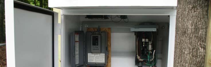
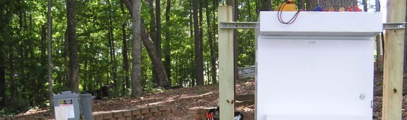
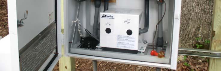
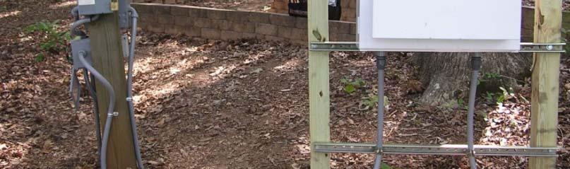
3 Proposed Solution Create a new separately derived source that is ground isolated to feed the dock s loads. The secondary side ground would be bonded to dock equipment as it normally would, but this ground would have no reference to the distribution system neutral. This would reduce or eliminate the neutral to water voltage at docks. Dock Isolation Unit 3


4 Test Site 1 Permanent isolation transformer installation. Only tested with transformer secondary grounded. NEV hazard was mitigated by use of the isolation transformer. Contact voltage hazard was also mitigated. NEV Measurements Without Iso Tx With Iso Tx Loc V exp-oc V exp-cc * V exp-oc V exp-cc * Fr-W Fr-W Deck-W *Closed circuit it voltage = exposure current Isolation Tx had ground on secondary All measurements in Volts (V)
5 Circuit Configuration - 1 5


6 Test Site 2 Test site with lowest NEV measured (under 10V). Tested with transformer secondary grounded and floating. NEV hazard was mitigated by use of the isolation transformer. Contact voltage hazard was also mitigated. NEV Measurements Without Iso Tx With Iso Tx 2 Loc V exp-oc V exp-cc 1 V exp-oc V exp-cc 1 Fr-W / /0.1 Fr-W / /0.5 Light 2-W / /0.3 1 Closed circuit voltage = exposure current 2 For Iso Tx readings: (with secondary grounded/with secondary floating) All measurements in Volts (V)
7 Circuit Configuration - 2 7
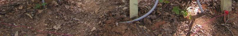
8 Test Site 3 Testing was performed at an additional site where the highest NEV measured was over 50V. NEV hazard was mitigated by use of the isolation transformer. Contact voltage hazard was also mitigated. NEV Measurements Without Iso Tx With Iso Tx Loc V exp-oc V exp-cc * V exp-oc V exp-cc * Fr-W Fr-W Deck-W *Closed circuit voltage = exposure current All measurements in Volts (V)
9 Neutral Exposure Voltage Magnitude at Site 3 Approximately 48Volts NEV is related to running of a local pump storage hydro plant 9
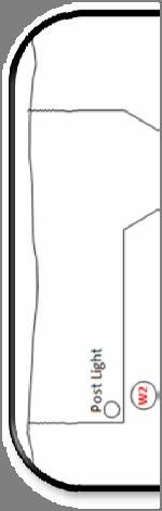
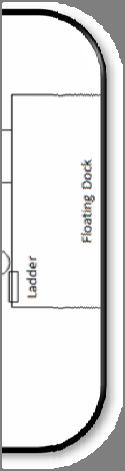
10 Boat Dock Testing at Site 3


11 Stray Voltage Testing Open Circuit Voltage Open Circuit Volt tage (Volts s) Isolation Transformer Bypassed Isolation Transformer In with Secondary Grounded Isolation Transformer In with Secondary Lifted/Floating 0 Site 1 Low Site 1 High Site 2 Low Site 2 High Site 3 Low Site 3 High * * *Configuration not tested 11


12 Stray Voltage Testing Closed Circuit Voltage 25 ltage (Volts) rent (ma) d Circuit Vol posure Curr Closed Exp Isolation Transformer Bypassed Isolation Transformer In with Secondary Grounded Isolation Transformer In with Secondary Lifted/Floating 0 Site 1 Low * Site 1 High * Site 2 Low Site 2 High Site 3 Low Site 3 High *Configuration not tested 12


13 Contact Voltage Testing Open Circuit Voltage age (Volts) Open Circuit Volt Isolation Transformer Bypassed Isolation Transformer In with Secondary Grounded Isolation Transformer In with Secondary Lifted/Floating *Configuration not tested; results would have been similar to sites 1 and Site 1 Low Site 1 High Site 2 Low Site 2 High Site 3 Low Site 3 High * * 13

14 Contact Voltage Testing Closed Circuit Voltage Clo osed Circuit Vol ltage (Volts) Exposure Curr rent (ma) Isolation Transformer Bypassed Isolation Transformer In with Secondary Grounded Isolation Transformer In with Secondary Lifted/Floating *Configuration not tested; results would have been similar to sites 1 and Site 1 Low Site 1 High Site 2 Low Site 2 High Site 3 Low * Site 3 High * 14
15 Change Proposal Language (555.16) Mitigation of Neutral Related Stray Voltages and Currents To provide protection for neutral related stray voltages and currents, a suitably rated isolation transformer (a separately derived system) at the branch circuit service panel supplying the shore power shall be permitted. The following configuration is recommended for the isolated system: (1) The isolation transformer shall have overcurrent protection on the supply side as required in (2) The isolation transformer shall be provided with a ground fault protection device on the load side. (3) Metal enclosure of the transformer shall be connected to the supply side neutral and grounding system as required dby 2504(A) (A). (4) The load side neutral and equipment grounding conductors shall be connected together and grounded on the secondary side of the transformer as required by (B). 20(B) To provide adequate isolation, the installed grounding electrode shall be located at least 6' from the nearest grounding electrode of the supply side and shall be connected to the transformer by an insulated grounding conductor. (5) The location of the isolation transformer shall be on the load side of the service disconnecting means and shall not be below the electrical datum plane. 15
16 NEC Change Proposal Results Submitted Changes for: Article 555 Marinas and Boatyards (Code Panel 19) Results Reject Panel Statement: The installation of a transformer intended to isolate stray voltage (current) is not presently prohibited. The proposed method of connection and grounding of a separately derived system is not in accordance with Article It was noted that Class B ground fault circuit interrupters are no longer permitted by UL 943. The panel requests that this panel action be provided to Panel 5 for their information with reference to Proposal 5-92.
17 Change Proposal Language (682.16) Mitigation of Neutral Related Stray Voltages and Currents To provide protection for neutral related stray voltages and currents, a suitably rated isolation transformer (a separately derived system) at the branch circuit service panel supplying the shore power shall be permitted. The following configuration is recommended for the isolated system: (1) The isolation transformer shall have overcurrent protection on the supply side as required in (2) The isolation transformer shall be provided with a ground fault protection device on the load side. (3) Metal enclosure of the transformer shall be connected to the supply side neutral and grounding system as required by (A). (4) The load side neutral and equipment grounding conductors shall be connected together and grounded on the secondary side of the transformer as required by (B). To provide adequate isolation, the installed grounding electrode shall be located at least 6' from the nearest grounding electrode of the supply side and shall be connected to the transformer by an insulated grounding conductor. (5) The location of the isolation transformer shall be on the load side of the service disconnecting means and shall not be below the electrical datum plane. 17
18 NEC Change Proposal Results Submitted Changes for: Article 682 Natural and Artificial Made Bodies of Water (Code Panel 17) Results Reject Panel Statement: The Code is not a design document. The Code does not preclude such installations in general. Note that Class B GFCIs are not currently listed.
19 Comments / Contact Info Frank C. Lambert, P.E. Georgia Tech / NEETRAC frank.lambert@neetrac.gatech.edu a eet ac.gatec.edu
National Marine Manufacturers Association Compliance Specialist Examination A.C. Electrical (2018 Model Year) ABYC E-11 Supplement 56
 ABYC E-11 Supplement 56") 1. Two Electrical Technicians are discussing markings that are required for AC wiring. Tech A says that AC conductors must be rated for 600 volts and must have their jackets and individual conductors marked
1. Two Electrical Technicians are discussing markings that are required for AC wiring. Tech A says that AC conductors must be rated for 600 volts and must have their jackets and individual conductors marked
Stray Voltage and Swimming Pools
 Stray Voltage and Swimming Pools Marty L. Page, P.E. Southern Company malpage@southernco.com October 19 th 2009 2009 Jodie Lane National Conference for Stray Voltage Detection, Mitigation & Prevention
Chapter 1. Applied Grounding and Bonding. Applied Grounding and Bonding 9/18/2011. Introduction. Introduction. Paul Dobrowsky Member NEC Panel 5
 Applied Grounding and Bonding Paul Dobrowsky Member NEC Panel 5 1 Introduction This presentation is a representative sample from the following Chapters of Applied Grounding and Bonding. Chapter 1, Introduction
SAFETY AND HEALTH STANDARD ELECTRICAL GROUNDING Effective Date: 07/17/10 Standard: Document Number: KUCSH0039 Rev: 4
 SAFETY AND HEALTH STANDARD ELECTRICAL GROUNDING Effective Date: 07/17/10 Standard: 16.10 Document Number: KUCSH0039 Rev: 4 16.10.1 INTRODUCTION 16.10.1.1 The intent of this standard is to ensure that continuity
Electrical requirements for plans on all new homes, additions, remodels & Service upgrades
 CHERRY HILLS VILLAGE COLORADO Electrical requirements for plans on all new homes, additions, remodels & Service upgrades Due to the size and uniqueness of homes built in Cherry Hills Village, a policy
MECKLENBURG COUNTY. Land Use and Environmental Service Agency Code Enforcement 9/8/10 ELECTRICAL CONSISTENCY MEETING. Code Consistency Questions
 conduit? 9/8/10 ELECTRICAL CONSISTENCY MEETING Code Consistency Questions 1. Can branch circuits of different services be installed in the same Yes, see 300.3(C)(1) for conductors of different systems
MECKLENBURG COUNTY. Land Use and Environmental Service Agency Code Enforcement 2/9/11 ELECTRICAL CONSISTENCY MEETING. Code Consistency Questions
 MECKLENBURG COUNTY Land Use and Environmental Service Agency Code Enforcement 2/9/11 ELECTRICAL CONSISTENCY MEETING Code Consistency Questions 1. I have a 500 KVA generator, with no overcurrent protection
2/15/2015. Current will always try to return to its source. In order for there to be current, there must be a complete circuit
 Current will always try to return to its source In order for there to be current, there must be a complete circuit Current will take as many paths or circuits available to it to return to the source The
Grounding and Bonding
 Grounding and Bonding 2017 Communications Academy Joe Blaschka Jr., PE Grounding/Bonding What is it? Why do we do it? What does the National Electrical Code say? What about fixed locations? What about
Grounding for Power Quality
 Presents Grounding for Power Quality Grounding for Power Quality NEC 250.53 states that ground resistance should be less than 25 ohms. Is this true? Grounding for Power Quality No! NEC 250.53 states
Section 6: System Grounding Bill Brown, P.E., Square D Engineering Services
 Section 6: System Grounding Bill Brown, P.E., Square D Engineering Services Introduction The topic of system grounding is extremely important, as it affects the susceptibility of the system to voltage
Alternating Current Power
 Chapter 4 Alternating Current Power MElec-Ch4-1 Overview What is Alternating Current AC Hazards AC Power Requirements Shoreside Utility System On-Board Generators MElec-Ch4-2 What is Alternating Current
Electrical Wiring: Commercial, Seventh Canadian Edition
 Electrical Wiring Commercial Canadian 7th Edition Mullin SOLUTIONS MANUAL Full download at: https://testbankreal.com/download/electrical-wiring-commercialcanadian-7th-edition-mullin-solutions-manual/ Unit
FTTH ENGINEERING AND INSTALLATION INTRODUCTION
 1 FTTH ENGINEERING AND INSTALLATION INTRODUCTION GROUNDING FTTH SYSTEMS AT THE HOME. By Dean Mischke, P.E., V.P. Grounding and bonding. Why are we worried about such an old school concept in the modern
Grounding and Bonding of Service Equipment
 Grounding and Bonding of Service Equipment 1. Grounding means: attached to an earth ground. 2. Bonding means: physically connected to insure electrical continuity. NEC 250.4 1. Grounding: Electrical Systems
PREFACE ********************************************************** IT IS NOT INTENDED THAT THESE STANDARDS BE COPIED AND USED AS A SPECIFICATION!
 PREFACE This publication has been prepared as a guide for Architectural and Engineering (A&E) firms in the preparation of documents for the design and construction of new structures and the remodeling
CHAPTER 15 GROUNDING REQUIREMENTS FOR ELECTRICAL EQUIPMENT
 CHAPTER 15 GROUNDING REQUIREMENTS FOR ELECTRICAL EQUIPMENT A. General In a hazardous location grounding of an electrical power system and bonding of enclosures of circuits and electrical equipment in the
Overview of Grounding for Industrial and Commercial Power Systems Presented By Robert Schuerger, P.E.
 Overview of Grounding for Industrial and Commercial Power Systems Presented By Robert Schuerger, P.E. HP Critical Facility Services delivered by EYP MCF What is VOLTAGE? Difference of Electric Potential
Wisconsin Contractors Institute Continuing Education
 IMPORTANT NOTE: You should have received an email from us with a link and password to take your final exam online. Please check your email for this link. Be sure to check your spam folder as well. If you
Table K. Input/Output Ratings & External Wiring Requirements for the Powerware /80 Rating 50/60 Hz. kva kw VOLTS VOLTS / /220
 Table K. Input/ Ratings & External Wiring Requirements for the 9390-/ Units Rating 50/0 Hz Basic Unit Rating at 0.9 lagging pf load Input and Bypass Input Rectifier (0.98 min. pf) plus Recharge Current
UNION COUNTY ENGINEER DIVISION OF BUILDING REGULATIONS
 UNION COUNTY ENGINEER DIVISION OF BUILDING REGULATIONS Residential Pool Permit Requirements FEES: A nonrefundable permit application fee of $25.25 and a nonrefundable plan review fee of $40.40 will be
TN, TT & IT Earthing Arrangements
 TN, TT & IT Earthing Arrangements In IT and TN-C networks, residual current devices are far less likely to detect an insulation fault. In a TN-C system, they would also be very vulnerable to unwanted triggering
GROUNDED ELECTRICAL POWER DISTRIBUTION. Excerpt from Inverter Charger Series Manual BY: VIJAY SHARMA ENGINEER
 GROUNDED ELECTRICAL POWER DISTRIBUTION Excerpt from Inverter Charger Series Manual BY: VIJAY SHARMA ENGINEER .0 Conductors for Electrical Power Distribution For single-phase transmission of AC power or
17TH EDITION BS TH EDITION BS7671 HOW THIS AFFECTS YOU. A BITESIZE LOOK at RCDs and parts of the 18th edition DPC. wylexreasons.co.
 BS7671 BS7671 AFFECTS YOU. A BITESIZE LOOK at RCDs and parts of the 18th edition DPC. wylexreasons.co.uk CONTENTS. INTRODUCTION. CHAPTER 31. WHAT IT SAYS ABOUT DIVISION OF THE INSTALLATION. INTRODUCTION
IEEE Southern Alberta Section, Industrial Applications and Power & Energy Chapter Technical Program. Venue: Operator. Speaker Travel: Stantec
 IEEE Southern Alberta Section, Industrial Applications and Power & Energy Chapter Technical Program Venue: Grounding Ark Tsisserev Thank you to our Sponsors! Alberta Electrical System Operator Speaker
IEEE WORKING GROUP ON VOLTAGES AT PUBLICLY AND PRIVATELY ACCESSIBLE LOCATIONS. Web Cast May 17, 2007
 IEEE WORKING GROUP ON VOLTAGES AT PUBLICLY AND PRIVATELY ACCESSIBLE LOCATIONS Web Cast May 17, 2007 CHAIR CHUCK DENARDO (414) 221-3073 (chuck.denardo@we-energies.com) VICE CHAIR JIM BOUFORD (508) 421-7648
2014 NEC Changes Part 1
 www.garyklinka.com Page 1 of 8 Instructions: Fee $20 1. Print these pages. 2. Circle the correct answers and transfer them to the answer sheet. 3. Page down to the last page for the verification forms
A DUMMIES GUIDE TO GROUND FAULT PROTECTION
 A DUMMIES GUIDE TO GROUND FAULT PROTECTION A DUMMIES GUIDE TO GROUND FAULT PROTECTION What is Grounding? The term grounding is commonly used in the electrical industry to mean both equipment grounding
EPRI Contact Voltage R&D Program Update Doug Dorr EPRI
 EPRI Contact Voltage R&D Program Update Doug Dorr EPRI ddorr@epri.com 407-968-3010 2009 Jodie Lane Annual Conference October 19 th 2009 Presentation Summary This summary contains excerpts from the materials
Description & Applications Questions & Answers Selection Charts Single Phase Selection Charts Three Phase...
 SECTION BUCK-BOOST TRANSFORMERS A simple and economical way to correct offstandard voltages... from 95 to 500 volts; single and three phase, in sizes up to 60 kva. Simplified buck-boost rating charts make
EPG. by Chris C. Kleronomos
 April 1994 EFFECTIVE EQUIPMENT GROUNDING ECOS Electronics Corporation by Chris C. Kleronomos The quality of the electrical wiring and grounding in a facility containing sensitive electronic equipment is
B. Manufacturers: Square-D, G.E. or Westinghosue.
 SECTION 16470 - PANELBOARDS PART 1 - GENERAL 1.01 RELATED DOCUMENTS A. General: Drawings and general provisions of the Contract, including General and Supplementary Conditions and Division 1 Specification
Continued from Part 1 Rules 1 25.
 Continued from Part 1 Rules 1 25. 26 225.32 Disconnect Location The disconnecting means for a building or structure must be installed at a readily accessible location, either outside the building or structure
NOTICE OF RULE MAKING PROCEEDINGS AND PUBLIC HEARING
 1 1 1 1 1 NOTICE OF RULE MAKING PROCEEDINGS AND PUBLIC HEARING NORTH CAROLINA BUILDING CODE COUNCIL Notice of Rule-making Proceedings is hereby given by NC Building Code Council in accordance with G.S.
Article 225: Outside Branch Circuits And Feeders
 Part C: Code Book Questions Article 225: Outside Branch Circuits And Feeders 1.! Open (individual) aerial overhead conductors shall be insulated or covered when within! feet of a building.! (a) 10! (c)
ER 87 Electrician Regulations Answer Schedule. Question 1 Marks Reference Marking notes. (1 mark) ESR 27(2) (2 marks) ESR 74A(1AA)
 ESR 27(2) (2 marks) ESR 74A(1AA)") ER 87 Electrician Regulations Answer Schedule Notes:1. (1 mark) means that the preceding statement/answer earns 1 mark. 2. This schedule sets out the expected answers to the examination questions. The
ER 87 Electrician Regulations Answer Schedule Notes:1. (1 mark) means that the preceding statement/answer earns 1 mark. 2. This schedule sets out the expected answers to the examination questions. The
NEC 2014 Code Changes
 NEC 2014 Code Changes Articles 200-215.3 CHANGES FROM 2011 CODE ARE IN RED Chapter 2 - Wiring and Protection ARTICLE 200 Use and Identification of Grounded Conductors 200.2 General Grounded Conductors
ECE 528 Understanding Power Quality
 ECE 528 Understanding Power Quality http://www.ece.uidaho.edu/ee/power/ece528/ Paul Ortmann portmann@uidaho.edu 208-316-1520 (voice) 1 Today Wiring and grounding Why it s important References Terms and
AGENDA. NEC Code-Making Panel 5. Report on Comment Meeting. November 28-December 1, Redondo Beach, CA
 National Fire Protection Association 1 Batterymarch Park, Quincy, MA 02169-7471 Phone: 617-770-3000 Fax: 617-770-0700 www.nfpa.org AGENDA NEC Code-Making Panel 5 Report on Comment Meeting November 28-December
To Float or Not to Float? Analysis of a floating vs. grounded output Associated Power Technologies
 To Float or Not to Float? Analysis of a floating vs. grounded output Associated Power Technologies Introduction In electrical circuits, voltage is always measured between two points: a point of high potential
Ground Fault Location. Turbo Sleuth. Instruction Manual
 Ground Fault Location Turbo Sleuth Instruction Manual 7615 Kimbel Street, Mississauga, Ontario Canada L5S 1A8 Tel: (905)673-1553 Fax: (905)673-8472 Toll Free: 1-888-RESISTR 737-4787 www.ipc-resistors.com
Selective Coordination for Emergency and Legally-Required Standby Power Distribution Systems
 Selective Coordination for Emergency and Legally-Required Standby Power Distribution Systems Presented for the IEEE Central TN Section / Music City Power Quality Group August 1, 2006 By Ed Larsen and Bill
Los A LA-UR Los Alamos National Laboratory Los Alamos, New Mexico 87545
 LA-UR-98-1 Los Alamos NationalLaboratory is operated by the University of California for the United States Department of Energy under contract W-7405-ENG-36 TITLE: SUBMITTED TO: Electrical Potential Transfer
AN EXAMPLE OF A STANDARD ARC FLASH PPE LABELING STRATEGY
 The Electrical Power Engineers Qual-Tech Engineers, Inc. 201 Johnson Road Building #1 Suite 203 Houston, PA 15342-1300 Phone 724-873-9275 Fax 724-873-8910 www.qualtecheng.com AN EXAMPLE OF A STANDARD ARC
UNITY/I TM. Installation Manual. UT3K, UT4K, UT5K and UT8K. Single-Phase Uninterruptible Power Systems
 UNITY/I TM UT3K, UT4K, UT5K and UT8K Single-Phase Uninterruptible Power Systems Installation Manual MLS-0351C-OL Copyright 1994-1997 Best Power. All rights reserved. å IMPORTANT SAFETY INSTRUCTIONS! SAVE
high RESISTANCE GROUNDING SYSTEM the power to protect SLEUTH Instruction Manual C-408EM
 SLEUTH high RESISTANCE GROUNDING SYSTEM SLEUTH the power to protect Instruction Manual C-408EM HIGH RESISTANCE GROUNDING Sleuth Protecting your equipment and processes from damaging ground faults, a resistor
SECTION PANELBOARDS
 PART 1 - GENERAL 1.1 DESCRIPTION SECTION 26 24 16 PANELBOARDS SPEC WRITER NOTE: Delete between // --- // if not applicable to project. Also, delete any other item or paragraph not applicable in the section
ELECTRICAL SHOCK HAZARD DUE TO STRAY CURRENT THE SHOCKING SHOWER
 ELECTRICAL SHOCK HAZARD DUE TO STRAY CURRENT THE SHOCKING SHOWER Copyright Material IEEE Paper No. I&CPS-99-XX Donald W. Zipse, P.E. Life Fellow, IEEE Zipse Electrical Engineering, Inc. 671 Kadar Drive
Journeyman's Practice Exam
 Journeyman's Practice Exam [Time limit 4.0 hrs.] (The test is open book. I've started at the front of the Code Book and worked toward the back for instructional purposes. The real test will not be in order
Unit 3 Magnetism...21 Introduction The Natural Magnet Magnetic Polarities Magnetic Compass...21
 Chapter 1 Electrical Fundamentals Unit 1 Matter...3 Introduction...3 1.1 Matter...3 1.2 Atomic Theory...3 1.3 Law of Electrical Charges...4 1.4 Law of Atomic Charges...4 Negative Atomic Charge...4 Positive
Isolation Fault Troubleshooting - Application Note
 Isolation Fault Troubleshooting Application Note Version 1.1 November 2017 Contents Version History... 1 Introduction... 1 Identifying an Isolation Fault... 1 Troubleshooting an Isolation Fault Using the
Customer Requirements RF Antenna Installations
 Application Terms Attachment requirements and clearances on the Pole for Radio Frequency (RF) antenna equipment installations. This standard is intended to allow electrical workers to perform their normal
Preface...x Chapter 1 Electrical Fundamentals
 Preface...x Chapter 1 Electrical Fundamentals Unit 1 Matter...3 Introduction...3 1.1 Matter...3 1.2 Atomic Theory...3 1.3 Law of Electrical Charges...4 1.4 Law of Atomic Charges...5 Negative Atomic Charge...5
Grounding Recommendations for On Site Power Systems
 Grounding Recommendations for On Site Power Systems Revised: February 23, 2017 2017 Cummins All Rights Reserved Course Objectives Participants will be able to: Explain grounding best practices and code
Evaluating Step and Touch Potential Risks on Earthing Systems of High Voltage Cable Systems TP, THINUS DU PLESSIS ESKOM SOUTH AFRICA HJ, HARTMUT JAGAU
 Technology solutions and innovations for developing economies Evaluating Step and Touch Potential Risks on Earthing Systems of High Voltage Cable Systems TP, THINUS DU PLESSIS ESKOM SOUTH AFRICA HJ, HARTMUT
American Electrical Institute
 American Electrical Institute Oregon Electricians Continuing Education Grounding & Bonding (Article 250) 4 Hours American Electrical Institute PO Box 31131 Spokane, WA 99223 www.aeitraining.com Article
EFCOG BEST PRACTICE # 211. Best Practice Title: Managing Hazards of Multiwire Branch Circuits Installed Before the 2008 NEC
 EFCOG BEST PRACTICE # 211 Best Practice Title: Managing Hazards of Multiwire Branch Circuits Installed Before the 2008 NEC Facility: DOE Complex Point of Contact: John (Jackie) McAlhaney, Savannah River
ENGINEERING STANDARD FOR INSTRUMENTS ELECTRICAL POWER SUPPLY AND DISTRIBUTION SYSTEMS FIRST EDITION MAY 2013
 ENGINEERING STANDARD FOR INSTRUMENTS ELECTRICAL POWER SUPPLY AND DISTRIBUTION SYSTEMS FIRST EDITION MAY 2013 This Standard is the property of Iranian Ministry of Petroleum. All rights are reserved to the
Upgrading Your Electrical Distribution System To Resistance Grounding
 Upgrading Your Electrical Distribution System To Resistance Grounding The term grounding is commonly used in the electrical industry to mean both equipment grounding and system grounding. Equipment grounding
Wiring of the Main Distribution Panelboard
 Job Sheet 4 Wiring of the Main Distribution Panelboard OBJECTIVE To connect the service-entrance conductors. To ground the main distribution panelboard (MDP). To wire a branch circuit supplying a three-phase
BECAUSE MOTOR & GENERATOR FAILURE IS NOT AN OPTION USCG
 PRODUCT CATALOG M O T O R & G E N E R A T O R P R O T E C T I O N BECAUSE MOTOR & GENERATOR FAILURE IS NOT AN OPTION USCG Why Your Equipment Needs MEG-ALERT Protection 1 2 3 4 5 6 7 How can you be sure
Instant-Off (I-O) Measurements on Decoupled Systems
 Measurements on Decoupled Systems") Instant-Off (I-O) Measurements on Decoupled Systems Important Considerations What Is A Decoupler? A device that has a very low impedance to ac current but blocks the flow of dc current up to a predetermined
Instant-Off (I-O) Measurements on Decoupled Systems Important Considerations What Is A Decoupler? A device that has a very low impedance to ac current but blocks the flow of dc current up to a predetermined
Single Earthed Neutral and Multi Earthed Neutral. Single Earthed Neutral and Multi Earthed Neutral: Multi Grounded Neutral System (MEN):
:") Single Earthed Neutral and Multi Earthed Neutral. SEPTEMBER 6, 2011 5 COMMENTS Single Earthed Neutral and Multi Earthed Neutral: In Distribution System Three Phase load is unbalance and non linear so The
Single Earthed Neutral and Multi Earthed Neutral. SEPTEMBER 6, 2011 5 COMMENTS Single Earthed Neutral and Multi Earthed Neutral: In Distribution System Three Phase load is unbalance and non linear so The
CURRENT FUTURE REGULATIONS PROPOSALS
 CURRENT REGULATIONS BS7671 FUTURE PROPOSALS BS7671 AFFECTS YOU. A BITESIZE LOOK at RCDs and parts of the 18th edition DPC. wylexreasons.co.uk CONTENTS. INTRODUCTION. CURRENT REGULATIONS. WHAT IT SAYS ABOUT
LOCATING MULTIPLE GROUND FAULTS THE BLUE CHIP CASINO IN MICHIGAN CITY, IN
 LOCATING MULTIPLE GROUND FAULTS THE BLUE CHIP CASINO IN MICHIGAN CITY, IN A SUMMARY REVIEW OF THE FINDINGS AND INVESTIGATIVE TECHNIQUES THAT WERE USED TO RESOLVE THE GROUNDING PROBLEMS Page 1 The Blue
CONTINUING EDUC ATION
 3 CONTINUING EDUC ATION FOR WISCONSIN ELECTRICIANS 2017 NEC Article 250 2 Hours WISCONSIN CONTRACTORS INSTITUTE N16 W23217 Stone Ridge Drive Suite 290 Waukesha, WI 53188 262-409-4282 www.wcitraining.com
FINAL - EST Electrical Service Technician Answer Schedule
 FINAL - EST 2069 - Electrical Service Technician Answer Schedule Notes:1. means that the preceding statement/answer earns 1 mark. 2. This schedule sets out the accepted answers to the examination questions.
Short Circuit Current Calculations
 Introduction Several sections of the National Electrical Code relate to proper overcurrent protection. Safe and reliable application of overcurrent protective devices based on these sections mandate that
Datawave Magnetic Synthesizer
 POWER PROTECTION Datawave Magnetic Synthesizer 100 kva to 200 kva; 50 and 60 Hz Installation, Operation, & Maintenance Manual TABLE OF CONTENTS IMPORTANT SAFETY INSTRUCTIONS............................................1
Jake Leahy s Electrical Code Connection. A look at Grounding and Bonding of Electrical Services Article Florida Building Code 5 th Edition
 Jake Leahy s Electrical Code Connection A look at Grounding and Bonding of Electrical Services Article 250 2014 Florida Building Code 5 th Edition Wiring Integrity. Completed wiring installations shall
Guide for Conducting a Stray Voltage Evaluation Under the MPSC Stray Voltage Rule 1
 Guide for Conducting a Stray Voltage Evaluation Under the MPSC Stray Voltage Rule 1 Introduction and Overall Purpose: This guide is intended to be used in conjunction with the administrative rules addressing
3Ø Short-Circuit Calculations
 3Ø Short-Circuit Calculations Why Short-Circuit Calculations Several sections of the National Electrical Code relate to proper overcurrent protection. Safe and reliable application of overcurrent protective
Note: The let-through of the protective device must be equal to or less than the short-circuit current rating of the component being protected.
 CONDUCTOR SHORT-CIRCUIT PROTECTION Introduction: This paper analyzes the protection of wire from fault currents. It gives the specifier the necessary information regarding the short-circuit current rating
TOSHIBA International Corp
 TOSHIBA International Corp GUIDE SPECIFICATIONS THREE PHASE UNINTERRUPTIBLE POWER SYSTEM TOSHIBA 4200FA 30 kva CT Internal Battery UPS GUIDE SPECIFICATIONS 1 (30 kva CT) 1.0 SCOPE 1.1 System This specification
Need for grounding Codes and Standards for grounding Wind Turbine Generator grounding design Foundation + Horizontal Electrode grounding design
 IEEE PES Transmission and Distribution Conference 2008 Panel Session Large Wind Plant Collector Design Wind Farm Collector System Grounding by Steven W. Saylors, P.E. Chief Electrical Engineer Vestas Americas
The Importance of the Neutral-Grounding Resistor. Presented by: Jeff Glenney, P.Eng. and Don Selkirk, E.I.T.
 The Importance of the Neutral-Grounding Resistor Presented by: Jeff Glenney, P.Eng. and Don Selkirk, E.I.T. Presentation Preview What is high-resistance grounding (HRG)? What is the purpose of HRG? Why
Healthcare Isolation Power Systems. Presented by: David Knecht
 Healthcare Isolation Power Systems Presented by: David Knecht E-Mail: David.Knecht@Bender-us.com Healthcare Isolation Power Systems Theory Offer Codes & Standards FAQs Isolated Power System Purpose To
Article 700: Emergency Systems. 2.! Audible and visual signal devices shall be provided, where practicable to indicate.
 Part N: Code Book Questions Article 700: Emergency Systems 1.! For emergency systems, the authority having jurisdiction shall conduct or witness a test on the! complete system upon installation and periodically
BUCK-BOOST TRANSFORMERS
 Where Are Buck-Boost Transformers Used? A typical buck-boost application is 120 volts in, 12 volts out for low voltage lighting or control circuitry. In most applications, this low voltage transformer
Low Voltage Products. Third Harmonic Filter THF and THF star System components for assembly and retrofitting. Catalogue THFS2GB 03_05 1SCC330004C0201
 Low Voltage Products Third Harmonic Filter and star System components for assembly and retrofitting Catalogue SGB _ SCCC System components for assembly and retrofitting star, installation in the transformer
High Frequency Sinewave Guardian TM Filter
 High Frequency Sinewave Guardian TM Filter 380V 480V TECHNICAL REFERENCE MANUAL FORM: SHF-TRM-E REL. April 2015 REV. 001 2015 MTE Corporation Caution Prior to start up; confirm the drive operation mode
2. Determine the number of Modules/Microinverters required. (1134 modules is 2 less than 250 KW but works well with max comm.
 Commercial System Design Guidelines Application Note 1. Introduction... 1 2. Determine the number of Modules/Inverters required.... 1 3. Determining the number of Microinverters per branch circuit... 1
HPS Universal BUCK-BOOST TRANSFORMERS
 BUCK-BOOST TRANSFORMERS Single and Three Phase Potted Buck-Boost Transformers Buck-Boost Applications & Standard Specification... 80 Selecting Buck-Boost Transformers... 81 Single Phase Selection Tables...
WAVEFORM CORRECTOR (WAVEFORM CORRECTORS) REPLACES SURGE PROTECTION DEVICES (SPD) PREVIOUSLY KNOWN AS (TVSS)
 REPLACES SURGE PROTECTION DEVICES (SPD) PREVIOUSLY KNOWN AS (TVSS)") WAVEFORM CORRECTOR (WAVEFORM CORRECTORS) REPLACES SURGE PROTECTION DEVICES (SPD) PREVIOUSLY KNOWN AS (TVSS) 1 PART 1: GENERAL This section describes materials and installation requirements for low voltage
WAVEFORM CORRECTOR (WAVEFORM CORRECTORS) REPLACES SURGE PROTECTION DEVICES (SPD) PREVIOUSLY KNOWN AS (TVSS) 1 PART 1: GENERAL This section describes materials and installation requirements for low voltage
POWER SERVICE DETAILS
 POWER SOURCE # POLE MOUNTED SERVICE TRANSFORMER BY POWER HANDHOLE 0/0V, -PHASE, SERVICE CONDUCTORS; -# AWG SERVICE CONDUCTOR AND -# AWG GROUNDED SERVICE CONDUCTOR (NEUTRAL) SERVICE XFMR SECONDARY. A 0V
High Frequency SineWave Guardian TM Filter
 High Frequency SineWave Guardian TM Filter 380V 480V TECHNICAL REFERENCE MANUAL WARNING High Voltage! Only a qualified electrician can carry out the electrical installation of this filter. Quick Reference
Measuring Networks 1
 DR. GYURCSEK ISTVÁN Measuring Networks 1 Sensor Circuits Sources and additional materials (recommended) Lambert Miklós: Szenzorok elmélet (ISBN 978-963-874001-1-3) Bp. 2009 Jacob Fraden: Handbook of Modern
PSSI 27 Work or Testing On or Near to High Voltage Direct Current (HVDC) Plant and Apparatus
 Plant and Apparatus") 1. SCOPE This Safety Instruction applies the principles established by the ScottishPower Safety Rules (Electrical and Mechanical) and the Company Safety Instructions to achieve Safety from the System for
1. SCOPE This Safety Instruction applies the principles established by the ScottishPower Safety Rules (Electrical and Mechanical) and the Company Safety Instructions to achieve Safety from the System for
Quality Control Checklist - Design Drawings
 Quality Control Checklist - Design Drawings Date Company Name Address Telephone Fax Email Job Number 1) Drawing Set a) Drawing one is site/location/incoming power i) Should contain location map if not
Grounding Complications
 Grounding Complications Sensitive Equipment Isolated grounding Supplemental grounds Sensitive Electronic Equipment NEC 647 [2002-2005] Originally intended for audio studios -- now Industrial/commercial
The InterNational Electrical Testing Association Journal. BY STEVE TURNER, Beckwith Electric Company, Inc.
 The InterNational Electrical Testing Association Journal FEATURE PROTECTION GUIDE 64S Theory, Application, and Commissioning of Generator 100 Percent Stator Ground Fault Protection Using Low Frequency
SERIES K: PROTECTION AGAINST INTERFERENCE
 International Telecommunication Union ITU-T K.21 TELECOMMUNICTION STNDRDIZTION SECTOR OF ITU (11/2011) SERIES K: PROTECTION GINST INTERFERENCE Resistibility of telecommunication equipment installed in
Testing the Ground Circuit
 Ground of electrical products Class I vs. Class II products Ground Continuity Test Ground Bond Test What is tested during each test Testing the Ground Circuit Meet Our Team Webinar Notes Please use the
Article 250 Grounding & Bonding
 Article 250 Grounding & Bonding AMERICAN ELECTRICAL INSTITUTE N16 W23217 Stone Ridge Dr. Waukesha, WI 53188 855-780-5046 www.aeitraining.com DISCLAIMER NOTE: This course is APPROVED for continuing education
ECET Fall 2017 Name: _ Lab Assignment #01
 ECET 4520 - Fall 2017 Name: _ Lab Assignment #01 General Instructions: This assignment is to be completed individually. All answers/work required for each problem should be neatly written in the space
DESIGN CHECKLIST INTRODUCTION
 INTRODUCTION 1 The checklist is intended to serve as a convenient guide in design development as well as the final checking of plans and specifications for construction projects. Its main usefulness for
NIPSCO Energy Symposium
 Backup Power Automatic Transfer NIPSCO Energy Symposium symposium Backup Power Applications/Considerations Backup Power Types Automatic Transfer Switch Basics Presenters McGill Power - Jeremy Irmeger Eaton
Technique for Accurate Voltage Measurement of Energized Street Level Objects
 Technique for Accurate Voltage Measurement of Energized Street Level Objects David Kalokitis (SM), Aaron Prazan (M) The demand and volume of stray voltage testing in urban areas have increased greatly
2018 Consultant s Handbook Division 26 Electrical ARC Flash Hazard Analysis
 1 Summary 1.1 Provide a complete Arc Flash Hazard Analysis for the project indicated in the accompanying RFP. The Analysis may be performed: independent of the construction project in concert with the
Electrical Occupations
 Job Ready Assessment Blueprint Electrical Occupations Test Code: 3029 / Version: 01 Copyright 2011. All Rights Reserved. General Assessment Information Blueprint Contents General Assessment Information