Projects, Audio,il ' idq,al, Computers, Radpo, Servicing, Education $1 so. electronic DECEMBER 1979 MM 70924
|
|
|
- Alison Taylor
- 6 years ago
- Views:
Transcription


1 Projects, Audio,il ' idq,al, Computers, Radpo, Servicing, Education $1 so electronic DECEMBER 1979 MM 70924


2 ***************************** IHe-Ne LASER KIT $ At last a sale (1111W 1 Helium Neon laser kit al an at fordable price. Kit of all parts and instructions. Ideal for optical experiments, holography, ranging,etc Transistor 1 W. amp V 1 Amp Power Supply 03 Strobelight 04 Light Chaser 05 Light Organ 500w/ch 06 Light Organ 1500w/ch 07 FM Mike 08 FM Mike, with preamp 09 Tone Decoder Timer board Code Oscillator Code Key, brass WWII 13 LED Blinky ULTRALINEAR POWER AMPLIFIER D LE I(IT POWER OUTPUT watts RMS into 8 or 4 ohms FREQUENCY RESPONSE - 21 Hz - 20 KHz ± 1db HARMONIC DISTORTION % at 1 KHz at 100 watts IM DISTORTION - 0.1% ARKON KITS TELEPHONE CURLY CORDS A great item for audio, Ham, CB, etc. 6 foot curled cord as used by MA BELL. Black, Brown, Red, Orange, Yellow, Green, White. 3/$5.00 OHIO SCIENTIFIC SUPERBOARD$41700 You've seen all the ads, at last this great item is in stock. What more can we say. FORT//80 $ Self Blinking LED's $ Video Modulator $ RS232-TTL Converter $ IC Amp I LM380) $ Crystal Radio $ Photo Electric Nightlight $ Channel Light Organ $ Shimmer Strobe Whisper Light $ MA1 i' lock $ 3.95 : -cision Maker 25 Hi -Power 12V Flasher $ AM -FM Freq. Readout FORT//80. is here at an affordable price. A fast, resident Fortran compiler. Produces directly executable, highly condensed machine code for :he 8080, (will run on Z80 and 8085). Runs on any CPO system. *Direct IU to 8080 ports *Accepts embedded in -line code Fortran Interrupt control *ANSI FORTRAN IV subset *Single, double precision *Custom 10 drivers *Memory mapped 10 *Made in Canaria Send now for a full data sheet and sample program. Copyright Arkon Electronics, Digital Research of Cal FORT//80, MANUAL ONLY (APPLIES TO BUY]. $20.00 DATA SHEET AND SAMPLE PGM.,. NC LED BAR GRAPH AND ANALOG METER DRIVER New from National Semi. #LM3914. Drives 10 LED directly for making bar graphs, audio power meters, analog meters. LED oscilloscopes, etc. Units can be stacked for more LED's A super versatile and truly remarkable IC. Just out, SPECIAL PRICE:$ 95 INCLUDES 12 Page Spec Sheet 10 Mini bar LED's $2.00 $ 2.95 $ 8.95 $ 9.95 $ 5.95 $ 4.95 $ 5.95 $ 5.95 $ 7.95 $ 8.95 $24.95 $ 3.95 $ 5.95 $49.95 ARKON CP-IO-1 The ARKON CP/10-1 is an S-100 card that ha all the CPU, Disc control and 10 capabilit needed to construct a disc based microproces sor system for business, hobby or scientifi system. Features are: 2 Mhz 8080-A, fully buffered S-100. EIA-RS232 port, 110 to 76,000 baud. Fully vectored interrupt (TMS-5501). 5 Interrupt controlled timers. EIA port for printer up to 9600 baud. Disc controller on board (1771). Shugart 400, 800, Memorex 550, plus. On board digital data separator. 2K bytes EPROM. 24 fully handshaked 10 lines. Dual mapped 10. MWRITE generation on board. *Software driven cassete interface. ARKON CPIO $ MAGNECRAFT 12V $3.95 D C 3PDT Relay, SPDT Co -Axial RF Relay 95 for antenna use, MHr $6 PARTS V V V V 100V -25A bridge Red LED S,M,L Green LED S,M,L Yellow LED S,M,L Bi-polar LED Kx Kx1 741 $01.40 $01.40 $ 1.95 $01.90 $ /1.00 4/1.00 4/1.00 $0.75 $11.95 $13.95 ARKON ELECTRONICS 409 QUEEN STW TORONTO ONT AE10 e INPUT IMPEDANCE - LOAD IMPEDANCE - SENSITIVITY V $44.95 f 100K ohms 4 ohms Min for 100 watts AE50 The AI'. -50 is a little brother to the Pecs spces but only 50 s atts. $29.95 SD SYSTEM EXPANDORAM Z-80 STARTER KIT.. $ K... $ SBC 100 KIT K... $ VERSAFLOPPY KIT $ K... $ K... $ VIDEO TERMINAL I(IT DISPLAY: 64 char per line x 16 line per Pram of 5x7 dot matrix, 64 ASCII char VERT SYNC: 60 Hz XTAL controlled HOR SYNC: KHz XTAL controlled VIDEO 0/P: IV P -P composite video I/O: Parallel port to ASCII keyboard +20ma current loop +RS BAUD RATE:110 to 9600 Baud remote sel POWER:5v 1A DC + +12VDG for RS232. RE6416 $ _OWER CASE POWER SUPPLY DPTION... $16.95 OPTION $16.95 WIRED and TESTED $ MEMOREX 550 /n ri /0, U e; e I I- I IBM compatible at a reasonable price in Can 3da. Ask for a data sheet as there is not enougt ;pace here to do justice to this high quality unit MEMOREX 550 DRIVE $ All orders processed promptly, add 5% for shipping. Excess refunded. Make sure you include complete Master Charge or Chargex numbers and expiry date, minimum order $5.00 Ont. Res. add 7%. t{argex

 BILL JOHNSON (Amateur Radio) JOHN GARNER")
 Ltd. Printed by Livingstone Printing Ltd Delta Web Graphics News Stand Distribution Master Media, Oakville.")

3 Vol.3, No. 12 DECEMBER 1979 ISSN Editor GRAHAM WIDEMAN BASc Assistant Editor JOHN VAN LIERDE ADVERTISING Advertising Manager MARK CZERWINSKI BASc Advertising Services CHERYL MAY Advertising Representatives JIM O'BRIEN Eastern Canada JEAN SEGUIN & ASSOCIATES INC. 601 Cote Vertu, St. Laurent, Quebec H4 L 1X8. Telephone (514) Subscription Department BEBE LALL Accounts Department SENGA HARRISON Layout and Assembly SARAH -JANE NEWMAN Contributing Editors WALLACE PARSONS (Audio) BILL JOHNSON (Amateur Radio) JOHN GARNER (ShortWave Listening) DICK CARTWRIGHT (Servicing ) STEVE RIMMER (Video) EDITORIAL AND ADVERTISING OFFICES Unit 6, 25 Overlea Boulevard, Toronto, Ontario, M4H 1B1 Telephone (416) Published by Electronics Today International (Canada) Ltd. Printed by Livingstone Printing Ltd Delta Web Graphics News Stand Distribution Master Media, Oakville. COPYRIGHT All material is subject to worldwide copyright protection. All reasonable care is taken to ensure the accuracy of the information. All ETI PCB Patterns are copyright. No company may sell boards to our designs without our permission. INTERNATIONAL EDITIONS Electronics Today International, 145 Charing Cross Road, London WC2H 8DEE, UK. Electronics Today International Ryrie House, 15 Boundary St., Rushcutters Bay, Sydney, Australia. Managing Editor Collyn Rivers. Acting Editor Roger Harrison Elrad Kommanditgesellschaft, Bissendorfer Strasse 8, 3000 Hannover 61 Germany Editor Udo Wittig Postal Information Second Class Mall registration number Return postage guaranteed. Post office returns to Unit 6, 25 Overlea Blvd., Toronto, Ontario. M4H 181 electronicsday INCORPORATING ELECTRONIC WORKSHOP HIGH PERFORMANCE STEREO PREAMPLIFIER.,... PROJECTS 14 High quality high fidelity project that's easy to build. DEVELOPMENT TIMER Check it out! A new way to do prints. LOGIC TRIGGER Homebuilt MPU got you down? This could help. LM10 THE BASICS A new op -amp? It's worth a look. FEATURES POLICE RADAR SPEED METERS.... Tool of justice? Bane of the common motorist? WHAT'S ALL. THIS'EAR How music turns you on PRACTICAL GUIDE TO TRIACS... First of a three part series. FLUORESCENT DISPLAYS Movementless meters. ETI EDITORIAL INDEX Last year's articles together for you NEWS &COLUMNS NEWS DIGEST..4 AUDIO TODAY 9 Wally Parsons time warps into the future and looks at vacuum tubes. SERVICE NEWS 55 Thinking of a job as a service tech? Dick Cartwright says why you should. SHORTWAVE WORLD 58 John Garner tells what you can do in 24 hours with your rig. QRM Bill Johnson muses on the implications of radar detector legislation. WHAT'S ON.71 Is there a flat TV in your future? Steve Rimmer reports. TEACHERS' TOPICS - 76 How to draw, good schematics. THE FUN OF ELECTRONICS Looks like Geiger has been doodling on our pages again. INFO & MISCELLANEOUS Next Month In ETI 18 Reader Service Card Sam's Books ,65,66 Subscriptions 62 Classified Ads 79 ETI Project File 80 Babani Electronic Books..,.,12,63 General Reader Information 82 ETI Market Place Advertiser's Index,.., TAB Books ETI CANADA-DECEMBER 1979


4 NEWS DIGEST Jobs For Professionals Still At Record Levels Job vacancies for accountants, engineers, scientists and other professionals reached record levels at the end of September. The Technical Service Council's quarterly survey of openings with 1,600 firms showed demand increased 3% since June 1979, and 34 /o in the last 12 months. "Canadian employers still have confidence in the economy, as evidenced by their active recruiting," according to N.A. Macdougall, general manager and director of the Technical Service Council/Le Conseil de Placement Professionel. "Although there is concern about the effects of the downturn in the American economy, employers are equally concerned about their inability to hire experienced professionals." Shortages of specialized engineers, data processing staff and accountants have intensified during the last year. Employers in every region of the country report problems filling openings for experienced professionals. A survey of 17 major consulting and resource firms in Alberta showed shortages of senior engineers, planners, schedulers, systems specialists and auditors. These employers expected recruiting problems to worsen during the next six to twelve months. The TSC's national survey showed systems analysts and computer programmers were in greater demand than any other group. Who says university grads don't get jobs? Professional occupations offer job satisfaction and security in a changing economy. (photo courtesy of Apple Computer Inc.) Large university graduating classes provide a good supply of trainees. However, companies who failed to recruit in universities in the Spring report difficulty hiring 1979 graduates in commerce and most engineering courses. A few civil engineers a"ré still unplaced. Arts, general science, physics and life science graduates have had difficulty finding responsible positions. A strong demand was reported for electronics technicians and technologists, instrument engineers, petroleum engineers, chemical process engineers, personnel managers, plantsuperintendents, mechanical draftsmen and accountants. The TSC is financed by some 650 companies. There is no charge to job hunters. The TSC has put on free "how to job hunt" courses and financed three major studies of the supply of and demand for university graduates and accountants. Bryce, Haultain personnel consultants, a TSC division, undertakes relocation counselling, executive search, employment interviewing courses and personnel consulting. APF'S IMAGINATION MACHINE APF Electronics Inc. believes their new computer: The Imagination Machine is the first user programmable and expandable computer (retailed as low as $500 US) which will be educational, entertaining, fun and easy to operate by consumers. APF marketing representatives feel The Imagination Machine is the solution to the personal computer problem in that the consumer was previously afraid to operate a computer. APF offers a preliminary cartridge which will instruct the new user in programming the computer through directions on the screen in front of them. This program also eliminates the confusing, head turning of learning from a manual beside you and instead, gives commands to easily teach the various computer capabilities on the screen as you perform them. The Imagination Machine will offer color graphics, music synthesizer plus a detailed software program covering education, home management and games. Hand held joysticks and key pads are part of the attractive unit which has 9K RAM expandableto 32K and 10K ROM. Write to APF Electronics Inc., 444. Madison Ave., New York, NY SOLAR CELL FUTURE Dr. Raj Singh, former member of a sizeable team of University of Waterloo solar cell researchers (now at Colorado), has some reservations about the extent to which some utility producers have locked themselves into nuclear power. He is extremely optimistic about the fairly short-term future of solar cells. Henotesthatinthepastfouryears the price of these cells has been reduced by a factor of 10 and predicts the day of the truly cheap cell is a good deal closer than many people realize. The three keys to the solution of the problem: (1) cheaper materials; (2) less of them; (3) automated production. On campus, he was working with metal insulator semiconductor cells. 4 ETI CANADA-DECEMBER 1979
 ratings of 300, 350 and 400 volts respectively. All devices have maximum collector current IC ratings of 8 amperes.")


5 TO 220 DARLINGS Motorola now has three new high - voltage, Darlington power transistors, available in the industry -standard TO outline for plastic packages. These devices, designated the MJE5740, MJE5741 and MJE5742, have Vceo(sus) ratings of 300, 350 and 400 volts respectively. All devices have maximum collector current IC ratings of 8 amperes. They are designed for high - voltage power switching in inductive circuits. The TO -220 package provides a maximum power dissipation of 80 watts at 25 C case temperature. These TO -220 power darlingtons are particularly suited for operating switch - mode applications such as Small engine ignition, Inverters, Switching regulators, Solenoid and relay drivers, Motor controls. The Darlington power transistors are priced, in quantities, at THUMB WHEEL Wherever limited space prevents the use of conventional wrenches, this new "Thumb Wheel" Ratchet Set comes to the rescue. Lets the user reach the tight places behind the dash, under the hood, in the trunk with good leverage and maneuverability. Ideal for installing and servicing radios, CB's, etc.; working inside TV sets; assembling cabinets and electronic gear. Made in the U.S. to the highest standards and is Warranted for life, the complete 8 -piece Thumb Wheel Ratchet Set, with pouch, is $14.95 US plus $1.00 for postage and handling. Satisfaction fully guaranteed. From: Howard Products Company, P.O. Box 57246, Dallas, Texas around a dollar. Delivery is from OEM and authorized Motorola distributor stocks. NEW WIRE WRAP SYSTEM O.K. Machine and Tool Corporation (New York) has announced "Just Wrap" a revolutionary wiring process and a series of tools that produce wire wrapped connections without prior stripping or slitting of the wire insulation. Designed to wrap on.025 in. (0,63 mm) sq. posts, each tool carries a 50 ft. (15m) spool of 30 AWG (0,25mm) wire. The tool will wire continuously through any number of pins (daisy chain). It is equipped with a built-in wire cutoff, and is equally suited for pointto-point wiring. Wire is available in 4 colors: blue, white, red and yellow. For further information Len Finkler Limited, 25 Toro Road, Downsview, Ontario, M3J 2A6. ETCO CAT One of North America's most unique electronics parts and equipment catalogues has just been released by Etco Electronics. Labeled issue "H" this catalog is the largest yet to be issued by Etco and contains many new items not in their previous issues. The book consists of 80 pages filled with unusual and hard -to -find parts, choice factory "termination" material and hundreds of bargain priced items. This catalog is available from Etco Electronics, Dept. 113, Box 796. Plattsburg, N.Y A CAT NAMED BRYAN Bryan Electronics has a catalogue out featuring a wide selection of LEDs, TTL, CMOS, plugs, cables. capacitors and more. In addition there is no minimum order and $2.00 flat fee ($5.00 Yukon and NWT) on any goods they sell. Write to Bryan Electronics, P.O. Box 2068 Bramalea, Ontario L6T 3S3. DIGITAL C. METER The CSC Model 3001 Digital Capacitance Meter is a high -precision 31/2 -digit instrument designed for measuring. testing, selecting and matchingcapacitance. But here its resemblanceto other cap meters ends. It is designed for high - volume, heavy-duty tasks in production and quality control, as well as critical applications in laboratories and servicing. The 3001's unique dual -threshold measuring technique delivers 0.1% accuracy - that's 0.1% of reading, not of full scale. This technique also eliminates errors resulting from dielectric absorption in capacitors. CSC instruments are available from Len Finkler Ltd. ETI CANADA-DECEMBER


6 THE 68000, IT'S HERE In Motorola's product line, the MC is the most advanced of the many MPU/MCUs that they have introduced over the past years. It doesn't obsolete the other types, however. Rather, it satisfies an applications void that currently exists between the upper capabilities of 8 -bit processors and the more sophisticated functions of the minicomputer. And -- the 16 -bit architecture and its unique high -level - language orientation offers Original Equipment Manufacturers a pervasive basic component with which to implement proprietary machines with minicomputer capabilities. A variety of MC68000-complementary peripheral chips are in design and will start becoming available early in But in the meantime MC68000 system implementation can be accomplished with the standard series of M6800 peripheral chips with which the new processor is compatible. This compatibility of components in Motorola's MPU/MCU family is one of the desirable features of the Motorola processor line, in that it permits hardward developed for one processor to be used with more powerful, upgraded systems. PET PORT TNW Corporation of San Diego now offers the TNW-2000 Serial Interface, an inexpensive unit that adds a bidirectional RS -232 port to the Commodore PET and other IEEE -488 computers. Users of these computers can now interface them to standard RS- 232 printers, terminals, and modems, and to other computers. Other devices can be used on the IEEE bus with the TNW-2000, and it can be used with other IEEE -488 capable computers as well as the Commodore PET. Al meter IEEE bus cable provides a daisy chaining capability with both the PET style edgeboard connector and the IEEE -488 Standard ribbon connector. Priced at $229 US, the TNW-2000 is delivered as a fully assembled and tested unit with cabinet, IEEE bus NEWS DIGEST Production of the MC68000 is being expanded. It is expected that all sampling requirements will be filled on an "as required" basis before the end of 1979, with production quantities becoming available during Introductory prices for MC68000 products are MC68000 $ US and the MEX68KDM Design Module $ US. cable, female EIA (RS -232) connector, and full documentation. Contact TNW Corporation, 3351 Hancock Street, San Diego, CA LOW POWER MEMORIES Three memory microboards, new additions to RCA's expanding line of microprocessor -based milliwatt-powered Microboard computersystems are now available immediately. The three new Microboard memories include the CDP18S621V1 16 -kilobyte RAM, the CDP18S kilobyte RAM, and the CDP18S kilobyte battery - backup RAM. Each module features static CMOS components with low - power and high noise immunity advantages and operates from a 5 -volt supply. Typical current requirements are 11 ma for the CDP18S621V1, 8 ma for the CDP18S623, and 13 ma for the CDP18- S624. The CDP18S624 battery -backup RAM, with its rechargeable Ni -Cad batteries on board, has a 96 -hour memory -retention capability with external power off. In quantities of 1 to 9, the CDP18S62-1V1 16 -kilobyte RAM is priced at $ US, the CDP18S kilobyte RAM is priced at $ US APPLE EDITORS Apple Computer, Inc., announces the Apple Writer a powerful text editor for the Apple II personal computer. Available now the Apple Writer offers a low-cost way to edit and print text, letters and documents. With the attachment of a dot matrix - or impact -type printer and a television screen, the Apple II and Apple Writer become a time -saving tool for producing and revising documents. The Apple Writer allows anyone to reduce the amount of time and effort spent on paperwork. A document needs to be typed into the computer only once; revisions or changes can be accomplished easily and quickly. Additional documents or documents segments (e.g., paragraphs) can be merged into any location within the previously typed document. The Apple Writer - as well as the Apple II personal computer - is made by Apple Computer, Inc., a leading personal computer manufacturer located in Cupertino, California. The Apple Writer, available as of November nationwide at all authorized Apple dealers, will retail for $75 US and the CDP18S kilobyte battery - backup RAM is priced at $ US. These prices are U.S. only. RCA COSMAC Microband Computer System products are available from RCA Solid State distributors. Further information may be obtained from RCA Solid State Division, Box 3200, Somerville, New Jersey ETI CANADA-DECEMBER 1979


7 Light up a Party: for exactly 1/1000 sec. (366 times a second) with Jana's Xenon Strobe The whole world will look fantastic! When room light is by Jana Xenon Strobe, your party will become magical.. as if the guests included Tolkien's hobbits, C.S. Lewis's lion, and a Cabell witch Ẇhen it's off, the secret of the powerful little Xenon tube will be seen by everybody. Turn the Jana case over and let them marvel at the intricacies inside. That might be as much of a show for them as the light that goes ONOFFONOFFONOFFONOFFONOFFONOFFOh. All this you can accomplish for your friends and yourself. Jana makes it possible for you with an illustrated plan that is easy to follow, and a clever selection of parts that do the job... all of it. Even the case is included. t1n0ff0n0 Check the list of Jana kits for many that are useful as well as those that make parties exciting. JANA KITS #1. Automatic Headlight Reminder #2. Battery Operated Fluorescent Light #3. Bug Shoo #4. Code Oscillator #5. Crystal Radio #7. Curiosity Box II #8. Dally Lighter #9. Decision Maker #10. Fish Caller #11. Hi Power 12V DC Flasher Jana kits are available from dealers across Canada, including Atwater Electronics Limited 886 Dundas Highway East Mississauga, Ontario L4Y 2B8 #12. Photo Electric Night Light # V Power Supply #16. Single Channel Color Organ #17. Electronic Siren #18. Shimmer Strobe Light #19. Tone Generator #20. 5 Transistor 1 Watt Amplifier #22. Xenon Strobe Circle No. 7 on Reader Service Card. #23. 3 Channel Color Organ #24. Loudmouth Siren #25. Roulette Wheel #26. Electronic Skeet Game #27. Electronic Dice #28. Super Roulette #29. FM Mini Broadcaster #31. Shoot Out #32. Road Runner #33. Love -O -Meter #34. Soldering Iron Kit #35. Audio Power Watt Meter Jana! INDUSTRIAL ELECTRONICS 1777 Ellice Avenue, Winnipeg, Manitoba R3H OW5


8 A SOUND IDEA Ever wonder how much noise you're exposed to during an average day? Well, now there's a handy, easy -to -read chart that illustrates the noise levels in a variety of environments with a colorful "noise thermometer". The chart, available free from Bruel & Kjaer Canada Limited, a company specializing in noise measurement, shows how much harmful noise you may be exposed to in typical daily situations, measured in both decibels and equivalent upa units. The examples illustrated range from the threshold of hearing at O decibels to the point where noise becomes painful at 140 db. Since each 3 db increase means the volume of sound has about doubled, the changes become increasingly significant at higher levels. For example a secluded wooded area registers a very quiet 15dB, much lower than normal conversational speech at about 60 db. The noise level in the living room of a well-behaved family is usually a relatively quiet 40 db, about equal to that in a public library, while a bedroom at 25 db is nice and quiet for sleeping. Copies of the chart can be obtained by writing Bruel & Kjaer Canada Limited, 90 Leacock Road, Pointe Claire. Quebec, H9R 1H1. BLOOD FROM STONE, OIL FROM WOOD Turning the Pacific Northwest's abundant supply of wood and other wastes to oil is a possible method for easing the regional energy shortage. Cellulose conversion to oil is one of the alternative energy sources researchers are studying at the Department of Energy's Pacific Northwest Laboratory. Battelle Memorial Institute operates PNL for DOE. Cellulose is the fibrous portion of a plant's structure and is indigestible to humans. Cellulose as an alternative energy source is present in renewable biomass - any residue from living organisms, including wood wastes, agricultural residues (stalks, stems, shells, husks, cobs), algae, kelp and manure. Included in the list are crops grown on "energy farms" specifically for use as fuel in biomass conversion projects. Cellulose in its pure form looks like powdered sugar, and can be converted to a thick black liquid using alkaline digestion with a catalyst under high temperatures (300 C) and high pressurs (1,000 psi). So far, over 100 of the most prevalent chemical compounds in NEWS I)IGI:ST JAPANESE THREAT TO NORTH AMERICA North America is in peril of losing its position as the world's leader in the field of technology, according to John Fluke Sr., speaking in Toronto to a gathering of top officials from Canada's electronics industry. John Fluke Sr., the founder and chairman of John Fluke Mfg Co., Inc., the world's largest manufacturer of digital multimeters and associates electronic instrumentation, was the keynote speaker at a technical seminar sponsored by Allan Crawford Associates Ltd. In his speech Fluke attacked Canadian and US educational systems which stress arts and crafts rather than teaching technology. "If we want to live in a world of crappy pottery and funny looking leather objects we can keep doing what we're doing. But I don't want to," he said. The biggest threat to North American technology comes from Japan, accord - A noisy poster? liquefied cellulose have been identi- fied. Cellulose is the major component of wood. Battelle researchers will study the other two components (lignin and hemicellulose) after completing the chemical characterization of cellulose oils. The product obtained from biomass liquefaction is not directly usable as a fuel oil, as many expected it would be. With further refinements, such as distillation, the "offensive smelling tar" could be converted to a heating oil and an extender for asphalt, another petrochemical product. Furthermore, the cellulose converted to oil could also be used as a chemical feedstock to make phenol or phenol compounds, chemical intermediates for making plastics, cosmetics and a range of other products dependent upon the continued availability of petroleum. ing to Fluke. "Their (Japan's) avowed purpose now is to go after computers (and) supremacy in the computer business means supremacy in the entire spectrum of electronics." LOOKING BACK Some months you can't do anything right... On page 38 of the November issuethe picture of TDS-M68 microcompter was pasted down upside down. I don't know how it got through, and I don't want to know. Also, Jerry Skye says he carries Moonlighter Electronics Kits. Gosh, Jerry you should have told us sooner. In addition he also has Arkon, Jana and many more. Talk to him at General Electronics, 5511 Yonge St, Willow dale, Ontario M2N 5S3. The remark in the Heathkit blurb 'The instructions are designed for peop!^ with previous experience in electronics...' should read without. I'd send in my resignation if I was sure I wouldn't screw it up. mum u,liii, I II Expose Yourself News digest is a regular feature of ETI Magazine. Manufacturers, dealers, clubs and government agencies are invited to submit news releases for possible inclusion. Submissions, or questions about material, should be sent to: News Digest, c/o ETI Magazine Unit 6, 25 Overlea Blvd., Toronto, Ontario, M4H 1B1. Audio products news will be directed to Audio Today's product department, and similarly Shortwave news will appear in Shortwave World. Sorry, submissions cannot be returned. 8 ETI CANADA-DECEMBER 1979


9 Audio Today \A/ally Parsons reviews latest developments in audio. THROUGHOUT MOST of the history of high fidelidy audio as we know it, the principal active deviceforamplification has been the vacuum tube. Although the transistor was first patented in 1926, it did not become a manufactured device until it was re -invented in the late '40's. Even so, these early germanium devices were so unreliable, performance so poor and so variable from one device sample to another that their application was limited to portable radios. There was simply no way that these devices could compete with advanced tube technology in any area except size, weight, and heat, none of which were considered of importance by any serious audiophile. But along about 1962 it was discovered that silicon was good for more than implants, and so the silicon transistor was born, and along with it a massive move towards solid state circuitry in audio technology. Naturally, a great deal of controversy arose as to the relative merits of tubes and transistors, but much of the dispute proved to be nothing more than the difference in the relative state of the two arts, and improved transistors and circuits gradually led to the supremacy of transistors and their subsequent dominance. It might, therefore, appear strange to be discussing tubes in audio applications today, and yet as recently as March 1977, the AESJournal published communications under the heading "Transistors Can Sound Better Than Tubes", complete with a microphone preamp circuit claiming to possess the virtues of tube circuitry. Not too long ago a Japanese manufacturer, yet, introduced a tube amplifier using circuitry very similar to the McIntosh MC60, and in England interest in tube equipment and "tube sound" has awakened, complete with typical British sound and fury. Much of it signifies nothing, of course. because so ETI CANADA-DECEMBER 1979 many proponents and opponents don't seem aware of the difference between "sound" and distortion. Accordingly, I thought it might be an opportune time to look at the operation of vacuum tubes and some applications, perhaps spread irregularly over several months. For a comparison of tubes, bi-polar transistors, and FET's, readers are referred to ETI for October and November, 1977 under "V-Fets for Everyone" THERMIONIC EMISSION All matter is composed of molecules, which in turn are composed of atoms, which are made up of many sub -atomic particles, including electrons. These electrons have some mobility, the exact amount dependent on the particular molecular structure, and its temperature. With some materials, particularly certain metals, heat can increase electron mobility to the point where electrons are thrown from the surface, much like molecules are thrown from the surface of boiling water to form steam. Of course, these electrons don't usually get very far, because their departure leaves a positive charge on the material which attracts them back again. But if the material isconnected to a supply of electrons, such as ground, an electron cloud forms around like steam. At this point, the electrons still aren't going anywhere, but if we place in the cloud's vicinity an electrode connected to a positive supply, electrons will be attracted to it. If they have to pass through air, operation will not be too efficient, but if the whole structure is enclosed in a vacuum, we now have a vacuum tube diode. The heated emitter of electrons, called the cathode may beeitherafilamentsimilar to that of a light bulb, and through which an electric current is passed, or it may be a sleeve electrically insulated from, fitted over, and heated by the filament. This cathode normally operates at a temperature which causes it to glow a dull red to a bright amber. The anode, or plate is of a suitable conducting material which encircles the cathode. If the plate is connected to a positive supply and the cathode to a negative supply, current will flow through the diode, while if polarity is reversed, there is no current flow. Thus, the device may be used for rectification. Notice too, that because of the mechanism of operation, it is best to consider its operation in terms of electron flow, rather than conventional current flow as we do with transistors. Fig 1. CATHODE ANODE (PLATE) Fig. 1 Physical configuration of a diode (AKA the 'Fleming Valve'.) CONTROL VALVE Our diode can be likened to a water pipe which allows water to flow in one direction only. By installing a valve in the pipe we can control the rate of flow from fully on to fully off, and continuously between. To accomplish this with our diode, we install a wire grid 9


10 between the plate and cathode. If a negative voltage is applied to this grid, the resulting charge will oppose electron flow, forcing them back to the cathode. We now have twb forces acting on the electrons, an attractive force due to a high voltage on the plate, and a repulsive force due to the lower voltage on the grid. The relative balance of the two will determine the final electron flow, yet the spacing between grid wires allows flow. By placing the control grid, as it's called, relatively close to the cathode, a low voltage can counteract the plate's high voltage. Thus, a small change in control voltage produces a large change in electron flow. If this changing grid voltage corresponds to a signal. then the resulting changes in electron flow will also correspond to that signal, provided it is allowed to operate only over a range in which control is linear. Fig 2 shows a typical transfer characteristic. Biasing Notice that the vacuum tube is a "normally on" device, unlike the bipolar transistor and Enhancement type MOSFET, which are normally off. Notice, too, that electron flow can only occur in one direction and that input and output are completely separate. Thus the output circuitry will not affect the input characteristics unless other circuit components are so arranged as to bring this about. If an alternating polarity signal is applied to the grid. on positive half - cycles electrons would flow through the grid. Although there are some circuits which actually drive the grid this way, usually in audio applications this is not desired, so a negative bias voltage is applied to the grid sufficient to prevent a signal from driving it positive. Thus, the grid is made more negative, or less negative by the driving signal. For single ended linear applications bias is usually set at some point which will allow maximum swing while remaining within the linear region of the transfer curve. As in transistor operation, this is described as "Class A" operation, which is defined as that bias condition in which current will flow during 360 of a cycle, and no grid current flows. Class B operation is possible, in which current flows only during 180 of a cycle. This is accomplished by biasing the tube to its cut-off. This is comparable to pinch -off operation of a J-FET, or zero -bias operation of a bi-polar device. Operation may also be Class AB, in which current flows for less than 360 but more than 180, and is accomplished by biasing somewhere between Class A and Class B, usually where the transfer characteristic begins to curve at the toe. Class AB may be further subdivided into AB1 and AB2. The numerical suffix signifies, respectively, that grid current may or may not be allowed to flow during positive half -cycles. In this case, input signal is allowed to exceed the bias value, and the signal source must be capable of supplying power. Audio applications are usually limited to high level modulation of AM transmitters. Biasing beyond cut-off results in Class C operation and is limited to RF transmitters. BASIC CIRCUITS Fig 3 shows the basic circuit for the triode tube we've been disc' issing. RL is a load resistor between B+ supply and the plate, and Rk isa biasing resistor. Rg is a rid leak resistor, and establishesthe DC ground reference for the grid. When current flows through the tube a voltage drop occurs across RL and across Rk. Because the negative supply is ground referenced, the cathode is at a positive potential with respect to ground. Since the grid is at ground potential, it is, therefore, negative with respect to the cathode. Current flow through RL results in a voltagedrop here, so that the plate is less positive than the B+ supply. If a negative going signal is applied to the grid, current is reduced, causing less voltage drop across each of the resistors; consequently, plate voltage increases, or becomes more positive. The reduced voltage drop across Rk results in the cathode moving closer to ground potential, that is, less positive (or more negative). A positive going signal produces the opposite results. Thus, we see that the output at the plate is in reverse phase to the grid input, while the signal on the cathode is in phase. Notice, too, that since the instantaneous voltage on the grid and cathode are changing in phase, the grid -cathode voltage is less than the grid -ground voltage. Since the cathode is common to both the input and output circuits, the cathode resistor introduces negative feedback. The cathode resistor can be bypassed with a capacitor to bring the cathode to AC_ground potential, but this introduces a low frequency phase shift which may not be desireable. Another method of biasing connects the cathode to ground, and the low end of the grid resistor to negative supply of the desired value. Triode construction. ";, ittiiii üguíiiloí(?) du. nri,dn 1.1f,ll PI ATE VOl Fig. 2 Typical transfer characteristics of a triode. PENTODES Fig 4 shows another type of tube which contains a couple more grids. The first grid is the control grid already described. The function of the second grid, called the screen grid is to accelerate electron flow to the plate. Because it is closer to the cathode, it has greater effect on electron flow than the plate, but because of its open structure, most of the electrons shoot past the grid to the plate. As a result, plate current is practically independent of plate voltage. The supply to the screen is normally fixed at some value below that of the plate, so only the control grid controls current. Unfortunately, at signal swings large enough to cause large current flows, plate voltage can drop below that of the screen. Electrons striking the plate at high velocities dislodge electrons from 0-1 rvi RI Fig. 3 Typical triode circuit. F192Cg2 Fig. 4 Biasing a pentode. 10 ETI CANADA-DECEMBER 1979


11 the plate, producing secondary emission. If the plate is at a lower voltage level than the screen, these electrons will be attracted to the screen, resulting in a reduction in plate current. To overcome this, a suppressor grid is placed between the plate and the screen and the plate, and connected to the cathode. Because it is at cathode potential, it forces secondary electrons back to the plate. To prevent screen voltage from varying with the signal, the screen resistor, Rg2 is normally bypassed to ground with a capacitor. As with cathode bypassing, this introduces a phase shift which may be undesirable. The alternative is to leave out the capacitor and allow feedback to develop across the resistor, or to supply the screen from a separate regulated É Y ñ supply. This latter course is often used in output stages designed for maximum output. Other types of tubes are sometimes in use, but these are the most common for audio applications. Next month, a look at some circuits you can use. Egg -250V Pentode transfer curves. Audio Today Letters Eg_ OV V Want to express your views or report on news? Write to Audio Today, ETI Magazine, Unit Six, 25 Overlea Blvd., Toronto, Ont. M4H 1B1. Thanks for your circuit on how to make LEDs random flicker. They look good in the miniature fireplace. I have some other questions for you that I hope you do not mind answering for me. Your magazine is the only contact I have with up-to-date audio and electronics. I have read in articles that to hear stereo the proper way in relation to live audio that there is supposed to be a third speaker connected to the amplifier. This speaker is placed between the Left and Right speakers. Could you please tell me how this speaker is connected and what are the advantages of having it. Does it play sound from both left and right, or??? Also, I have noticed a lot of digital tuning and digital VU meters coming on the market. Could you tell me some of the advantages of these. I have noticed that big brand names such as Technics and Akai are coming out with more mechanical tuners, etc. Will there be a complete change over to digital or will both be marketed for a while. Finally, I noticed or heard of a Dolby Test Tape. Is there such a tape for testing your Dolby and do you know Where I could get one and the approximate price. I have a cassette deck here with Dolby, but it seems to cut out a lot of highs and ends up leaving hiss. Are there different types of Dolby circuits in respect to price or are they all standard? I appreciate any time you give me in answering my questions. A.J.B. Agassiz B.C. Jensen Triaxial 3 -Way Speakers Quite simply, the most advanced car stereo speaker ever For the best sound ever in your car. The first car stereo speaker with a woofer, a tweeter and a midrange. Identical in principle!o the best home stereo speakers. Jensen's midrange picks up a whole range of tones lost to any other car speaker. Write today for Free catalogues and the name of your nearest Jensen Dealer - ís-. len finkler limited 25 Toro Road, Downsview, Ontano M3J 2A6 Telephone ( Telex ETI CANADA --DECEMBER 1979 Circle No. 9 on Reader Service Card. Audio Today My crystal ball is not very reliable, which is why l don't play the horses and I let my wife buy the lottery tickets. However, i've never called an election wrong yet, so i'll try a little crystal gazing with regard to digital tuning and meters. The main advantage of digital readout is precision of reading. That is, you know exactly what the reading is. Resolution is determined by the number of decimal places available, and accuracy is generally better than a slide rule dial or a d'arsonval meter movement. The cost of such devices usually makes them inappropriate for use on inexpensive equipment, but I should imagine that in time the cost will come down relative to the other components, making them suitable for use in medium quality components. With regard to digital tuning, part of the cost lies in the conversion of frequency to voltage and from analog to digital. A true digital tuner, on the other hand, utilizes digital frequency synthesis for tuning, and digital readout is a natural. However, at the present time, frequency synthesis is a more expensive technique than coils and variable capacitors, although this may change in the future. Off -setting the increased cost, at least with the true digital tuner, is the vastly improved front end performance, particularly in regard to stability and improved capture ratio. I suspect that the cheapest tuners and receivers will feature a simple rotary knob directly mounted to a tuning shaft, along with an over -sized dial face, like many AM sets. Digital VU meters, when used for monitoring programme levels strike me as having an alien feel to them. What is needed here is the ability to sense what the level is. Nobody really reads a meter in terms of how many VU above or below the zero mark the instantaneous signal actually reaches, but rather how far from the magic position it goes. This is why scales are not subject to change from one manufacturer to another. The eye cannot follow the changing numbers rapidly enough for them to be useful unless the response can be slowed down or peak readings held, in which case LED readouts would be more useful. As a regular reader, you will by now have read the June issue in which reference is made to a centre channel speaker as well as derived ambience.. Briefly, the simplest method of hook-up involves lifting the return (ground) leads of each speaker and connecting them to each other. They are now in series across the left and right outputs. 11


12 Then connect the centre speaker from the junction of the side speaker return leads to the ground terminal(s) of the amplifier. If all speakers are phased such that the plus lead is the one to which, if the positive terminal of a battery is connected, the cone will be made to move out, then the plus lead should be connected to this junction. Strictly speaking, there's no such thing as a Dolby circuit, at least in the sense that we usually use the term. "Dolby" really refers to the system oil dynamic range expansion -compression with specified frequency parameters. Most recorder manufacturers can supply a suitable test tape for use with their own products, and I would suggest that you contact the manufacturer of your machine, his distributor, or dealer for such a tape. In my search for new stereo speakers, several questions have arisen in my mind with respect to the different kinds and combinations of drivers used in speaker systems. (Seeing as a good pair of speakers is a fair investment, I figured it would be better to have these answered by someone other than a fast - talking salesman). First of all, many of the larger systems now employ two mid -ranges, and some two tweeters as well. I have even heard of some that employ four of each. Other than increased power handling capabilities, what are the reasons and advantages to this, in these systems, and are they that much betterto warrant spending the extra money? (I amquitea serious listener, and want a good system). Secondly, there are many other systems that employ passive radiators. Again, what are the advantages of these. and do they have that much of an effect on sound? Finally, I would like to know something about piezo-electric tweeters, and how they compare with one or dome type tweeters. (I realize now that I have asked almost enough for you to write a complete column, however there are probably lots of other readers who would be interested in hearing about all this, and it would really help me in my search. Besides, I can't find a book that would answer these). P.D. Willowdale, Ont. You're not likely to find a salesman competent to advise on such matters; if he were, he wouldn't be a salesman. Either fast or slow talking. There are several reasons for employing multiple drivers within a given Audio Today. pass band. One of them is to impress the uninformed buyer. In some cases, though, the designer meant well, but was no more knowledgeable than the customer. Thus, if one driver worked, two or more worked even better. Often, too, multiple drivers are used in the mistaken belief that four junky tweeters will out -perform one good one. Then, of course, there is the belief that eight or more little speakers are the equal of one larger unit with the same radiating area. No matter how many times the fallacyof this notion is demonstrated, it continues to pop up. Four junky tweeters do not sound like an Electro -Voice T350; they just sound like four junky tweeters. Which is why most such speaker systems sound so bad. There are, however, legitimate reasons for using multiple drivers within a pass band. One of them is increased power handling, which also allows a lower cross -over or more gradual slope. Another is impedance control at driver resonance. The most useful is control of dispersion pattern. One of the reasons for the outstanding performance of the larger Infinity speakers above the lower mid -range is the arrangement of upper mid -range and tweeters in line arrays, resulting in wide horizontal dispersion, and narrow vertical dispersion. By tailoring the response of each driver in an array a well -controlled and uniform dispersion can be achieved. You'll notice that such speakers are not cheap. The passive radiator is the same as a port in a reflex system. It has the advantage of a radiating area equal to or greater than that of the driver, while not requiring either a very large enclosure or a very long duct. Like all reflex speakers, some exhibit spectacular performance, while others are nothing more than boom boxes. 1 plan a column on piezo tweeters at a later date, with special emphasis on the Motorola KSN 1025 horn and KSN 1033A driver. Briefly, though, the horn units are not too suitable where wide dispersion is desired, but they can handle lots of power, are very efficient, very smooth, can be made to exhibit a smooth characteristic, and are almost indestructible. What, only one complete column? Correction An embarassing typographical error slipped by us last month. The Audio - vision amp being reviewed was reported to have an output power of 18W. This should have read 18V, giving an output power of about 40WRMS into 8 ohms. Our apologies to readers and to Audio - vision. COLOR LED POWER LEVEL INDICATOR The latest advanced way of measuring audio power output Works as a pair of VU meters, and adds exciting sights to your sound system. 3 color LED display, each channel. Enjoy the "dancing color light" show while you enjoy your music. Responds to musical signals at much faster speed than conventional mechanical VU meters. Applicable to most power amplifiers. Very easy to build, and just hook up with the speaker output without affecting the sound. Operates on battery or AC adaptor. Display panel, plated fiberglass p.c. board and all electronic parts included. SAD -02 IS step display Front Panel size 8-1/4"x2.1/2" - 36 LED (4 colors) with peak, floating and gradual display. Suitable for 30W-200W/Ch max. power output amplifiers. -- Operates on DC 6--9V. KIT: $56.00 Assembled: $ step display also available. Write for details. Send cheque or money order. Add 10% for shipping and handling. Ont. residents please add 7% sales tax. MONEY BACK GUARANTEE. FREE REPAIR SERVICE. F- orfree audio kits catalogue. write to AUDIOVISION SERVICE P.O. Box 955, Stn. B, Willowdale, Ont. M2K 2T6 I -I I G -I -I 1 I=C:I-1 jewelry THE COMPUTER MEMORY PENDANT era A unique conversation piece and great.vay of letting your interest, be known Ten years ago soon a Jewel was unimaginable Tcda, 'Os 'ecnhology.s transforming our [hair - and the sot:e!y we live in The wn,le ceramic and quartz package attracts attention, while a croser look 'evea's lac n.tracacy and p'ec6ror, of the silicon crrau' This tsgn-tech symbol hl the sevenfres is a gonuil,e,troduc' :' the mic,c efechon,c revolution Pendant available on gold pla!ed chain $18.95,gord filled chain $ k gold chain $32.000' as a suck pm $16.95 Send check or money order plus$1.00 postage and handling to'. HIGH-TECH Jewelry 3 Canterbury Road Is' i ngton,ontario, M9A-5B2 Please find enclosed cheque or moneyorder for pendant on.gplr 1.GFI orspl_i Name Address,10kG LCity Prov. Post Code J 12 FTI CANADA-DECEMBER 1979


 $2.")
13 ETI MARKET PLACE FREE PERSONAL ADVERTISING! We will allow up to thirty-five words to advertise items you want to buy or sell, or to publicise meetings of clubs, etc. Advertising will be accepted at our discretion-we will not accept commercial or any form of company advertising. For more insertions, mail again. ATTENTION 1802 USERS! A CANADIAN 1802 MONTHLY SOFTWARE BULLETIN IS AVAILABLE. FOR INFORM- ATION WRITE TO: BRIAN MATTHEW 19 FRENCH CRES. REGINA, SASK. S4R 6N3 MEASUREMENTS 82 & HICKOK 295X LAB. SIGNAL GENS. W/MANUALS. GUARANTEED GOOD. R.H. FRANSEN, 227 COTTONWOOD AVE., SHERWOOD PARK, ALTA T8A 1Y FOR SALE: TWO 8K RAM BARE BOARD, S-100, NOT EVEN TAKEN OUT OF PACKAGE $30.00 EACH. BRIAN MATTHEW 19 FRENCH CRESENT, REGINA. SASK. S4R 6N3 WANTED: STRIP CHART OR FLAT BED RECORDER, TUBE OR TRANSISTOR. WILL BUY MECHANICALLY COMPLETE BUT NON-OPERATING INSTRUMENT IF PRICE RIGHT. J. COCHRANE, 2815 RONALD RD. VICT- ORIA B.C FOR SALE: IMSAI MICROCOMPUTER, 22 BOARD POWER SUPPLY, 11 SOCKETS INSTALLED, 4K STATIC RAM BOARD, FULL DOCUMENTATION $ OR BEST OFFER. (416) OSHAWA. IF YOU LIKE TO HELP DESIGN AN ELECTRONIC CIRCUIT FOR MY ELECTRICAL INVENTION, I'LL SEND THE COM- PLETE DESCRIPTION. YOU CAN TAKE IT FROM THERE. ERNEST MALTAIS, 100 TAMARACK STREET, TIMMINS, ONTARIO P4N 6P6 WANTED: ETI'S IN VERY GOOD CONDITION, THE OLDER THE BETTER. MICHAEL WEISS 16 ROSEMARY AVE. LAKE WILCOX, ONTARIO. LOG 1X RARE TUBES --ORIGINAL CARTONS --VALUES $20.00 AND UP-IC7G-2A3-1B4P-34, ETC.-$10.00 EACH --RUSH. CASH SALE, OR C.O.D. SERGE BEAUDOIN BOX 328, ST -- JOSEPH, BEAUCE P.Q. GOS 2V0 PHONE: , FOR SALE: PLANS FOR BUG SHOO (SCARES AWAY AND ATTRACTED BUGS) $2.00 PLANS FOR THE ELECTRONIC SHELL GAME- PLAYED SEVERAL DIFFERENT WAYS (NOT EXPENSIVE) AND FUN $2.00 FOR PLANS. GARY KUPKEE 114 MADDISON AVE. FREDERICTON N.B. E3A 2N4. WANTED: SCHEMATIC FOR EICO ELECTRONIC VOLT- METER, MODEL 221. RON HO, BOX 13, CROWELL, (SHEROSE ISLE.) NOVA SCOTIA BOW 150 FOR SALE: BOWERS & WILKINS PM -70 ES SPKRS. (1PR) EXCELLENT CONDITION. $ OR B.O. TEL. (416) :00 PM. - 4:00 PM. OR AFTER 1:00 AM. 35 WILEY ST., ST. CATHARINES, ONTARIO, L2K 4E8 WANTED: CORRESPONDENCE WITH SERIOUS ELECTR- ONICS BUG OR NUT; TO EXCHANGE IDEAS, ETC. WRITE STEPHEN KAWAMOTO BOX 165 ALDERGROVE, B.C. VOX TAO SHORT WAVE RECEIVER FOR SALE EXCELLENT HAMM- ARLUND HQ -180A RECEIVER $ M. POWELL JR. BOX 500 CARBONEAR, NFLD. AOA 1TO SELLING COMBINED SWEEP AND MARKER GENERATOR AND MARKER ADDER-RCA-WR514A. Bran NEW CON- DITION. SUITABLE FOR ALIGNMENT OF ALL TV REC- EIVERS. STAN PARRY, 92 BESSBOROUGH AVE; MON- CTON, N.B. ElE 1P7 U OF C STUDENTS WILL DO CUSTOM PROGRAMMING FOR COMMODORE PETS WITH OR WITHOUT PRINTER OR WITH OTHER IEEE -488 PERIPHERALS, SEND REQUIREMENTS FOR QUOTE. STEPHEN VERMEULEN 3635 UTAH DRIVE, N.W., CALGARY, ALBERTA, T2N 4A rtt... information about the things that interest you. Use ETI's handy Reader Service Cards. Page 62 has all the details. Individual numbers can be found under many of the ads in this issue. Circle the numbers for those ads that interest you, mail it to us and more information will be on its way, 'Look, Jasmin, TTL and CMOS ICs, transformers, cabinets and more! 1 want to find out more about these guys.' 'Oh Graham. ETI CANADA --DECEMBER


14 ETI Project High Performance Stereo Preamplifier This project is designed to complement our 60 watt low distortion amplifier module and forms part of a complete stereo system, our "Series 4000" project-to be described in a forthcoming issue. (etil POWER 9 TREBLE 6 SERIES 4000 sti,reo <Inilrlifier VOLUME Pnono Tuner Aux.1 Aux 2 SOURCE I OW CUT "U'T CUT M11T ^VO^:ESS MONO TAPE Sri:PEO 9OURCE BALANCE THIS stereo preamplifier is designed to drive two 60 watt, low distortion amplifier modules (ETI 470), described last month. The requirements for this preamplifier/control unit were set down after many hours of office discussion. In fact it would be fair to say that the final design was evolved, rather than conceived. Amóngst the first requirements were low hum and noise and low distortion - much lower distortion than the amplifier modules it would be required to drive. Low distortion in a preamplifier is relatively easy to achieve and makes the subsequent addition of a high quality class A headphone amplifier worthwhile. In the final design, we feel we have achieved performance figures well up front amongst commercial equipment. Features considered essential included loudness, high cut and low cut filters. These are common in commercial preamp/control units but lacking on most kit designs. The low cut filter incorporated in our design will effectively reduce bass rumble while the high cut filter is useful for reducing tape hiss or 'monkey chatter' and heterodynes from an AM tuner. The disc amplifier stage of a preamp must be capable of handling very high input signals before clipping to preserve 14 dynamic range, especially as moving coil cartridges with voltage boosting transformers and/or amplifiers are finding increasing popularity. The disc input of this design can handle 400 mv peak -to - peak before clipping, giving it a dynamic range in excess of 100 db! Finally, and by far the most difficult of our requirements to implement, was the idea that all switches and potentiometers be mounted directly onto the pc board, with as few links and external leads as possible. All this, while preserving an attractive and stylish front panel layout! The advantage of this is that assembly is easy. and straightforward and there is less room for wiring errors to creep in and, should it be necessary, the board can be removed for servicing in its complete, functional form. All interconnections to and from the board are via RCA sockets using standard audio 'jumper' leads. The 60 watt power amplifier module and this preamp/control unit project form the basis of our "Series 4000" high performance stereo amplifier project, complete details of which we plan to present next issue. CONSTRUCTION All the components, including the pots, switches and LEDs, are mounted onto the pc board. The board is then fixed, component side forward, behind the mounting panel of the case using standard 25 mm spacers and countersunk screws. A dummy facia - with the control markings etc on it, is subsequently held in place by the switch nuts. If all directions are followed, then construction is quite straightforward - it's easier to do than describe! Firstly, the mounting panel and facia must be cut and drilled to the dimensions shown on the drawing (or, you can mount everything off board. as shown at the end of this article). The drilled pc board may be used as a template. Dimensions shown in brackets refer to the facia panel which must be cut slightly smaller if you wish to use the same case tor your stereo as we have. The holes for the pot shafts are only 7 mm in diameter on the facia panel to ensure correct knob alignment. Countersunk holes are drilled in the mounting panel, but not in the facia, for the bolts securing the pc board through the spacers. Once the mounting panel and facia are drilled, carefully check the alignment of all holes with the corresponding holes ín the pc board. The drilling must be reasonably accurate. ETI CANADA-DECEMBER 1979
. 83 db unweighted (With respect to 10 mv phono input). Phono: Within 0.")


15 High Performance Stereo Preamplifier Distortion Hum and Noise Frequency Response ETI STEREO PREAMPLIFIER SPECIFICATIONS (Measured on prototype) 0.015% at 1 khz 0.015% at 10 khz (For all inputs, with 500 mv RMS output - distortion is mainly 2nd harmonic). 83 db unweighted (With respect to 10 mv phono input). Phono: Within 0.5 db of RIAA from 20 Hz to 20 khz (Follows new IEC curve). Other inputs: 20 Hz to 20 khz ± 0.5 db Subsonic rolloff: 6 db/octave below 20 Hz Output Tape output Sensitivity 7 V p -p before clipping 150 mv RMS For 500 mv RMS output phono: 3 mv RMS other: 150 mv RMS (Phono overload level is 400 mv p -p). Tone controls Bass: ± 13 db at 50 Hz Treble: ± 11 db at 10 khz Filters High: 6 db/octave, Loudness Mute switch Low: -3 db at 5 khz 6 db/octave, -3 db at 100 Hz 8 db boost at 15 khz and 10 khz. 20 db attenuation Once this mechanical work is completed the components may be mounted on the pc board. Start with the RCA sockets. Take care not to use too much force on the nuts and check that electrical contact has been made to the ground plane of the pcb using an ohm -meter. Join the centre pin of the RCA sockets to the pc board pads using lengths of tinned copper wire - refer to the overlay. Mount the potentiometers next so that their terminals are directly above the pads on the pc board. The lower pot terminals can be cut, bent down and soldered directly onto the pads. Connect the upper pot terminals to the pc board, as shown in the overlay, using tinned copper wire. All switches are mounted on the board using pig tail leads. The rotary is a type commonly' available almost anywhere. When mounting switches on the pcb, make sure all switch and pot bushings are in the same plane. Once the major parts are assembled onto the pc board, all the minor components may be loaded and soldered in place. Make sure that any large components (electrolytics particularly) are less than 25 mm high, otherwise they will foul the front panel. Check that all transistors, tantalums and electrolytics are correctly oriented. Refer to the overlay as you proceed. The switches and LEDs must be mounted and spaced correctly off the pc board. Solder 50 mm lengths of tinned copper wire onto each of the switch terminals and LED leads (see illustration). Pass the wires through the Above: The switches and LEDs have lengths of wire soldered on to them so that they can be inserted into the pcb before being attached to the front panel. They can then be soldered in place. This procedure ensures that there is no strain on the joints. Below: the completed unit. Full details of metalwork will be given in a later article, in which we will describe how to use this preamp with two of the ETI W units to build a highperformance, low cost stereo amplifier. ETI CANADA-DECEMBER
16 cr) NOTE ONE CHANNEL ONLY SHOWN COMPONENTS NUMBER FROM 100 UP FOR 2nd CHANNEL SWITCHES AND POTS ARE NUMBERED AS FOLLOWS SW 1b, SW26, SW3b, SW4b, SW5b, SW6b, RV1b, RV213, RV31;, RV4b R2 PHNOI INPOUT 1k R1 471 R3 <R4 5k6 5k6 O1 C c /RS 47k 02 +I C3 T 100N 25V I.15 V to 2nd 11 Channel 0, o Amp. R C4 3n3 I C2 100, I25 15 V to 2nd Channel Doc Amp. C5L_ k 10o 22tF-/VVV---1 I- CE C7 4-_1_ 25V 0 03 R9 1k R C8 220n L1. U10 C9 12n 10u 25V R12 220k SW2a C11 TUNER AUX 1 AUX 2 SWfa 2n2I SOURCE SW5a TAPE OUT SW3a R13 10k SW4a RV1a L LIN 014 1k5 BALANCE ON 2nd - CHANNEL TAPE/SOURCE 015 4k7 TAPE MON 5W6a SW7a VOLUME R17 15k R19 15k C12 T33n STEREO/MONO ON 2nd CHANNEL R16 8k , IIC14 R20 3n3 S15k IC13 T 33n RV2a 50k LOG C16 220n R21 220k R22 220k C15 25V 04 R23 4k R R11 220k 05 C17 1,. 25V R26 4k7 RV3a 100k LIN R28 12k R29 R27 12k 2200 PHONO TUNER AUX 1 AUX 2 C " R30 6k8 C19 T47n.15v 10 2nd CHANNEL LED 1 1 LED2 LED 4-15V TO 2nd CHANNEL C n2 2k2 SWSb 1C21 +1 C n100,,_ I 25 C25 TO POWER SUPPI Y OV ON O POWER SUPPLY C23 T100" R C28 10,, 25V + RV4a R33 25k C26 10k LIN 20p C V b 06 R35 220k C27: 25V R34 820k 1 b k2 e C V -15VO 38 90R OV OUTPUT TO POWER AMP -15v 111_ Fig. 1. Preamplifier circuit diagram. Only one channel has been shown for clarity. The component numbering of the other channel begins at 101. The signal from a magnetic cartridge is fed to the base of 01 via a low pass filter, (R2 and C1) for attenuation of radio frequencies. 01 and Q2 form a differential pair, each half operating at low collector current - to minimise noise- The output of the differential pair is taken from the collector of 01 and further amplified by Q3. Feed back is taken to the base of 02, the negative input of the differential pair, through the RIAA equalisation network. Overall gain of the phono stage is set by the ratio of the feedback network impedance to the value of R6. Subsonic bass roll -off of 6 db/octave, to conform to the new!ec 65 specification, is achieved by a high pass filter consisting of C8 and RV-2. Outputfrom the disc preamplifier is then fed via the Source Switch (SW5), Tape -Source switch (SW6), R15 and the volume control (RV2), to an emitter follower. 04. This emitter follower presents a high impedance for the aux inputs and a constant impedance for driving the filters. HOW IT WORKS When switched in, the loudness network boosts the high and low frequencies with respect to the midrange. In actual fact, all frequencies are attenuated but the midrange is attenuated more. When the loudness is switched out, R16 approximates the impedance of the network. Muting is achieved by switching R14 to earth. The ratio of R14 to R13 sets the attenuation to 20 db. C11 shunts high frequencies to earth for high cut, while C10 reduces low frequency content when switched in, providing low cut, A second emitter follower, 05, presents a constant impedance to the filters and acts as a low impedance source to the tone control stage. A Baxandall tone stage is used here, a common circuit in many designs. 06 is a gain stage with a bootstrapped collector load, via C28, to the output. Bootstrapping increases the gain by increasing the effective collection load impedance. 07 is an emitter follower connected directly to the collector of 06. This provides a very low output impedance. DC bias for 06 ís taken from the output. Some of the output signal is fed back to the tone controls and split into high and low frequencies by RV3 and RV4. By adjusting the controls the percentage of the input to the negative feedback signal appearing at the base of 06 can be varied thereby varying the overall gain of the amplifier at either high or low frequencies. The gain of the tone stage is set by the ratio of R37 to R38. As R38 is reduced in value the negative feedback is reduced and therefore the overall gain is increased. To preserve the very low output impedance of the pre -amplifier the balance control is placed ahead of, rather than after. the tone stage. Power supply filtering and decoupling is provided by 100 µf capacitors and resistors in each rail. Source indication is by LEDs from the ware section of the source switch. No current limiting resistor is on the pc board for the LEDs as one will be included in the power supply. (To be described). corresponding pc board holes for these components but do not solder them in place yet. Check that the LED leads are the right way round. Assemble the pc board onto the case mounting panel (using the 25 mm spacers and countersunk screws). Place the facia over the front panel, securing it in place with the switch nuts (three hands and a prehensile nose might help!.. a little sticky tape and deft juggling is all that's really necessary). Once you've got it all together the protruding wires may be soldered to the pc board. Ensure that no short circuits have occurred That completes the assembly. For servicing purposes the pc board and all --- switches, LEDs and pots operating controls -- may be removed all the simply by undoing several removing the facia and the countersunk nuts, screws beneath. ij


.")
17 -155 y15v Fig. 2. Component overlay. Note that lengths of shielded cable are used to connect the outputs of the disc preamplifiers to the selector switch. Resistors. all Y4W 5% R1, R k R2, R k R3, R4, R103, R104 5k6 R5, R105 47k.. R6, R R.. R7, R k R8, R k R9, R k R10, R k2 R11, R12, R111, R k R13, R k R14, R k5 R15, R k7 R16. R k2 R17 - R20, R117, R k R21, R22, R121, R k R23, R k7 R24, R R.. R26, R k7 PREAMP OU P SW1 LOW-CUT SW2 HI -CUT SW3 MUTE R27, R R R28, R29, R128, R k R30, R k8 R31, R k2 R32, R33, R132, R k R34, R k R35, R k R36, R37, R136, R k2 R38, R R Potentiometers RV1 50k single linear RV2 50k dual log RV3 100k dual linear RV4 25k dual linear Capacitors Cl, C C2, C3, C102 C4,C C5, C p ceramic. 1O0µ 25V electro. 3n3 mylar. 10n mylar PUTS i`f[ taqlmkrk1 HOLES LED SUPPLY LEFT CHANNEL INPUTS IGHT CHANNEL INPUTS UX 2 3Y AUX 1 LED 4 DOTTED acreemed CAel6 $oldereo oat COPPER 6106 OP PCE TUNER IGHT N -f.11_15_)... APE OUTPUT EFT MOMO/STEREO tiul,'it(q IA PF IFFT RIG4T L SW4 LOUDNESS PARTS LIST.. 20p ceramic.... Semiconductors C6, C106.. C7 1O0µ 25V electro Q1, Q2, C8, C n greencap 0101, MP C9, C l0µ 25V electro 03, Q103. 2N5086 C10, C n mylar Q4 -Q7, 0104 C11, C n2 mylar MPS 6515 C12, C13, C112, C n mylar LED1-LED4. red LED C14, C n3 mylar C15, C µ 25V tantalum Switches... (see text) C16, C n mylar C17, C µ 25V tantalum C18, C19, C118, C119 47n mylar C20, C120. mylar C21 100n mylar C V electro C23 100n mylar C24 1O0µ 25V electro C25, C V tantalum C26, C p ceramic C27, C28, V electro C127, C128. C29, C µ 25V electro SW1-SW4.. DpDT min toggle switch SW5 3 pole 4 pos rotary switch SW6 DpDT min toggle switch SW7 spdt min toggle switch Miscellaneous 14 RCA panel mounting single hole sockets, ETI 471 pcb, tinned copper wire, length shielded cable, 25 mm spacers, 30 mm screws, nuts, mounting panel and facia plate... 2n2 1µ.


18 NEXT MONTH... JANUARY 1980 ISSUE... THE FIRST ETI OF THE 80s! "Series 4000" stereo amp Combine the 470 and 471 amplifier modules into one high quality unit. HISTORY OF IGNITION SYSTEMS IN AUTOMOBILES Just when the &t*&!?$ beast won't start, maybe you can find some solace in knowing how it works. VALVES The completed stereo amplifier is shown here mounted in a logic probe PROBE TIP HOUSING LEDS I \l handsome rack -mounting case. rsatia truly low cost and versatile unit that can det ct pu Ises as fast as 500 ns. MORE ON THE LM Some exciting applications for a unique device. PLUS, all our monthly columns on Audio, Video, Servicing, Education, Amateur Radio, and Shortwave Listening. The articles mentioned here are In an advanced stage of preparation. Circumstances may dictate changes In the final contents. POWER SUPPLY LEADS DARNING NEEDLE IEPDXY IN POSITION) 18 SOFT WOOD OR PLASTIC WEDGE /RUBBER GROMMET CIGAR TUBE CASE ETI CANADA-DECEMBER mm 1.01


19 High Performance Stereo Preamplifier I you wish a more streamlined amplifier, you can mount the pc board horizontally, and make all connections via shielded cable. Unfortunately, the pcb pattern for the preamp was much too large to print. A copy of the layout is available from us. Send cheque or money order for $1.00 to Series 4000 Preamplifier, Unit 6, 25 Overlea Blvd., Toronto, Ont. M4H 1BI. Be sure to enclose a self stamped business envelope. Note, we will not process orders without an SASE. Next month, we will publish a power supply suitable for use with this preamplifier and 60W power amplifiers from November. For pcbs for this project please contact: Spectrum Electronics, P. O. Box 41660, Hamilton Ontario L8V 4L5, or B & R Electronics, P. O. Box 6326F, Hamilton Ontario L9C 6L9. Rear view of the assembled preamp, showing how the potentiometers and shielded cables are mounted. Note the use ' of pc mounting phono sockets for ease of assembly. Potentiometer connections to the pcb are made via lengths of tinned copper wire n 213-r O IEI IXI 1 9r-_ C T _- CTlxl TolEl A D IEI t.a HOLES MARKED A -6mm B - 4.5mm C - 3mm COUNTERSUNK D -- 10mm E - 7mm 413 HOLE SIZES IN BRACKETS ARE FOR FACIA PANEL ONLY BY DOTTED LINE.) ETI CANADA-DECEMBER 1979 FOR HEIGHT OF FACIA PANEL TRIM 4mm FROM TOP AND BOTTOM OF FRONT PANEL DIMENSION. (AS INDICATED ALL DIMENSIONS ARE IN MILLIMETRES DO NOT SCALE DRAWING 19


 forget the age, concentration and temperature.")


20 ETI Project Development 1 Timer The Watkins Factor method of development is little known and at present almost unused - is this due to the lack of a proper timer? Phil Cohen has designed one. IN 1893, a photographer called Alfred Watkins noticed that the time taken for an image to appear during the development of a photographic plate was a fixed fraction of the total development time. The Watkins Factor The phenomenon that Watkins noticed was that the total development time was a fixed number (called the Watkins Factor) times the period taken for the plate to be seen to darken initially. Now, whereas development time varies with temperature, concentration and 'age' of the developer, the Watkins Factor does not. If you develop a film for a fixed period, you must keep these three factors constant. If, however, you develop it using the Watkins Factor you can (within reasonable limits) forget the age, concentration and temperature. This is all very well, but you would have to be able to see the film as it develops. This is not feasible with modern high-speed panchromatic film, which has to be developed in complete darkness. For this reason the Watkins Factor has been all but forgotten, hardly rating a mention in modern textbooks. This print was developed in fresh, normally diluted developer. The print darkened after 15 seconds and total development time was 45 seconds. The Watkins Factor was thus 3. 1 Theory In the process of developing a print, developer slowly diffuses into the paper, reacting as soon as it reaches the photosensitized areas. The reaction is diffusion controlled. The reason why nothing appears for the first few seconds of development (called the 'induction period') is that the developer is still working its way into the paper. With film you can't watch it develop, with paper you can so the Watkins method of development timing should be extremely useful to the amateur who can't afford a constant -temperature bath for his developer. The Timer It works like this: you set the appropriate Watkins Factor (which is specific to a particular developer and paper) on the front panel control. When you put the paper into the developer, you push the switch to 'START'. As soon as the first image starts to appear, you flick it back to 'TIME'. At the end of the development period the buzzer will sound. Then pull the paper out of the dish, wash it and fix it... viola!, beautiful prints. With the developer diluted to half its strength this print was developed for 45 seconds. Clearly, it is underdeveloped. 2 It may take a hit of experiment to find the correct Watkins Factor. Once you have it, though, you need not bother too much about developer temperature and (within limits) its age and concentration. Building It Construction should begin with the pc board. Make sure all of the capacitors, diodes, transistors and ICs are inserted the right way round. RV2 and RV3 are upright' preset pots bent over to fit flat against the pc board. Mount C4 directly onto SW1, this keeps the batteries in place. The buzzer mounts on the end of the case with its leads passed through a hole. Note that the red lead goes to the '+' buzzer connection on the board. Make sure that you use the correct tags of RV 1. Refer to the wiring diagram. It is a log characteristic pot. A linear one will not have the same calibration scale. This print was developed in the diluted developer using the timer set for a Watkins Factor of 3. The result is very little different to the first print indicating that the Watkins Factor method is useful for 'old' developer. 3 DEVELOPMENT TIMER 20 ETI CANADA-DECEMBER 1979
.")
.")
. After this happens, turn it back about one -eighth turn.")
21 Development Timer SeH ii,,a Up After finishing the unit, disconnect the 'TIME' and 'START' wires from SW2. Solder them together and put the most sensitive current meter you have between this joint and OV (most medium-priced multimeters will do). Disconnect the wire which goes to the middle contact of SW2 and connect it to the + end of C4. Set R V1 to '2'. Switch on and adjust RV2 for a zero meter reading. What you have just done is to ensure that when the resistance of RV1 is at the '2' value, the current through Q1 is the same as that through Q2 (see 'How It Works'). This is to correct for differences between the two FETs which seldom have the same characteristic. Now adjust RV3. Turn it fully clockwise and then slowly rotate it until the buzzer sounds (if it doesn't - there's something wrong). After this happens, turn it back about one -eighth turn. The timer is now fully set up. Re -connect the unit as shown in the REAR VIEW OF FRONT PANEL Swt An interior view of the Timer. Note how the batteries are arranged. C4 can be seen mounted on the switch. This keeps the batteries in place when the box is closed. diagrams. Switch on and set SW2 to TIME'. Short out Cl temporarily to remove the charge put on it during the setting -up. With RV1 set to 2, switch SW2 to 'START' for five seconds and then push it back to 'TIME'. Five seconds later, the buzzer should sound. Summary The theory behind the use of this unit needs development. It should make a fascinating study for any photographer, amateur or professional. This device will make an interesting addition to any darkroom. Component overlay, including the front panel switch and potentiometer arrangements For pcbs for this project please contact: Spectrum Electronics, P. 0. Box 41660, Hamilton Ontario L8V 4L5, or B & R Electronics, P. O. Box 6326F, Hamilton Ontario L9C 6L9. ETI CANADA-DECEMBER
22 Ij ETI Project HOW IT WORKS Development Timer u The Watkins Factor is the ratio of two time periods. A timing circuit having one variable period, which you set, and one fixed period is arranged to indicate when the correct ratio of time periods has been reached. This is achieved by charging and then discharging a capacitor. The time taken to charge the capacitor is varied while the discharge time is fixed. The control used to vary the charging time is calibrated in terms of the Watkins Factor. When a capacitor is charged at a constant current, the voltage across it will rise linearly with time - or 'ramp' upwards. Similarly, when it is discharged at a constant current, the voltage across it will 'ramp' downwards. This technique allows good accuracy to be obtained in timing applications. In this circuit, the current at which the timing capacitance is charged is varied by means of a potentiometer control. Q1 is connected as a 'constant current' source; that is, it will only allow a constant current to pass, the amount being determined by R1 and RV1. The potentiometer RV1 sets the Watkins Factor. When SW2 is set to START, C1/C2 will charge via QI/R1/RV1, the voltage across it ramping upwards at a linear rate The lower the resistance of RV1, the higher the charging current causing C1/C2 to charge at a faster rate. The converse is also true. Q2 is connected as a 'constant current' sink - when SW2 is set to TIME, C1/C2 will discharge via Q2/RV2, these components 'sinking' the current. The discharge current will be constant and the voltage across C1/C2 will ramp down at a linear rate. A Watkins Factor of '2' requires equal charge/discharge times for C1/C2. So that the currents through Q1 and Q2 will be equal when RV1 is set for a Watkins Factor of 2, RV2 (a trimpot) is provided to set the current through Q2. This is used to calibrate the timer. When the timer is switched on initially, with SW2 in the TIME position, any positive voltage on C1/C2 will cause the output of 1C1 to go negative, drawing current through Q2/RV2, discharging the capacitors. Any negative voltage that may appear on C1/C2 will cause the output of IC1 to go positive. This will forward - bias DI and 'pull up' the voltage across the capacitors. The combined action of these processes ensures that the voltage across Cl/C2 stabilises at zero volts. When the timing period is commenced at the start of developing a print, SW2 is set to START. As CI/C2 charge, the output of ICI will go negative. When the image first appears on the paper, SW2 is set to TIME. Cl/C2 will then discharge, as previously explained, and the voltage across the capacitors will go to zero. At this time, the buzzer will sound. IC2 is arranged as a 'trigger'. When C1/C2 first begin to charge, the output of ICI goes negative. When this negative voltage passes the value of the negative voltage applied to the inverting input of IC2, set by RV3, the output of IC2 will go very rapidly to about -7 V. At the end of the timing period, the output of IC1 goes to zero volts. As this drives the non -inverting input of IC2, the output will swing rapidly from about -7 V to +7V. This will force a pulse of current through C3/R2, forward -biasing the base of Q3. When Q3 turns on the buzzer will sound. C3 will take about one second to charge, Q3 will not receive sufficient base current and the buzzer will cease its cacophony. It sounds not unlike the wheeze from expiring bagpipes! This project was designed by a homesick scotsman. D2 discharges C3 when the output of 1C2 goes low when next you turn SW2 to START. A pushbutton, PBI, allows you to abort a timing sequence by shorting C1/C2. Note that the buzzer will sound whenever the unit is turned on. IC2 will trigger as the output of IC1 will initially be zero and the output of IC2 will thus jump to about + 7 V, setting off the buzzer. PARTS LIS T N5484 9V r9v C:"-0 SW1 RESISTORS R1 R2 POTENTIOMETERS RV1 RV2 RV3 CAPACITORS Cl, 2 C3 C4 27k 12k SEMICONDUCTORS 1C1, M log 1M trim 250k trim Q1,2 2N N5831 D1, 2 1N914 33µ 10V tantalum 10µ 25V electrolytic 470µ 25V electrolytic MISCELLANEOUS pcb ETI 594 SW1 miniature dpdt toggle SW2 miniature spdt toggle 2 of 9V batteries with clips; case to suit; 9V dc buzzer and mounting bolts; knob with pointer N914 START TIME R1 27k RV1 1M LOG SW ov TANT 5 02 C2 2N N OV d 6V TANT RV2 1M PB1 P +9V C1 l+ + ICI 33µ T T V ov -9V 0 The circuit diagram. Cl and C2 are in parallel to achieve the required total capacitance and voltage rating. +9V 7 0V RV3 250k 2N5484 C3 10N 6 r, I -9V 1-9V 9V DC BUZZER +9V 03 R2 2N k b D2 1N914 BOTTOM VIEW 9 9V ETI CANADA-- DECEMBER 1979


23 New from NRI! 25"color TV that tunes by computer,programs an entire evening's entertainment. Just part of NRI's training in servicing TV, stereo systems, video tape and disc players, car and portable radios. Only NRI home training prepares you so thoroughly for the next great leap forward in TV and audio...digital systems. Already, top -of -the -line TV's feature digital tuning, computer programming is appearing, and new digital audio recording equipment is about to go on the market. NRI is the only home study school to give you the actual "hands-on" training you need to handle servicing problems on tomorrow's electronic equipment. Because only NRI includes this designed -for -learning, 25" diagonal color TV with electronic tuning, built-in digital clock, and computer programmer as part of your training. With this advanced feature, you can pre-program an entire evening's entertainment...even key lock it in to control children's viewing. Exclusive Designed -for -learning r oru env eliinr'i'\ vnii niimbi as par' if n,ui Masts uui: upea es, 1116 pertc, ns like the ver', finest col-mot-rill >rts In! behind that pretty picture is a unique designed-toi learning chassis As you assemble it, von perform meaningful experiments. You even intro duce defects, troubleshoot and correct them as you would in actual practice. And you end up with a magnificent, big -picture TV with advanced features. Also Build Stereo, Test Instruments That's just a start. You demonstrate basic principles on the unique NRI Discovery lab then apply them as you assemble a fine AM/FM stereo, complete with speakers. You also learn as you build your own test instruments, including a 5" triggered sweep oscilloscope, CMOS digital frequency counter, color bar generator, and transistorized volt -ohm meter. Use them for learning, use them for earning as a full- or part-time TV, audio, and video systems technician. Complete, Effective Training Includes Video Systems You need no previous experience of any kind. Starting with the basics, exclusive "bite - size" lessons cover subjects thoroughly, clearly, and concisely. "Hands-on" experiments reinforce theory for better comprehension and retention. And your personal NRI instructor is always available for advice and help. You'll be prepared to work with stereo systems, car radios, record and tape players, transistor radios, short-wave receive,:. cal instrument amplifiers, electronic TV games; even video taoe recorders and tape or disc video playbacks. Send for Free Detailed Catalog 1.1ir postage ualic,,d today for our free 100 -page catalog with, le- photos of all kits and equipment, compute lesson plans, convenient time payment plans, and information on other electronics courses. You'll also find out about NRI's new Computer léchnology Course that includes your personal microcomputer. Or Complete Communications with 2 -meter transceiver. If card has been removed, write to: Mil Schools McGraw-Hill Continuing Education Center 330 ProgressAvenue Scarborough, Ontario M1P 2Z5 I I or telephone /91


24 ETI Project Logic Trigger Debug complex logic circuitry with this unit. WHEN USING AN oscilloscope to examine or fault find digital circuitry, it is often desirable to see what happens just before a pulse or edge occurs. An example of this is when measuring the propagation delay in a ripple counter. Here it is easy to trigger on the last output but the edge of the counter input which initiated the change in the output may have occurred over 100 ns earlier. Even with the delay line built into modern oscilloscopes the edge is too early to see. Triggering on the input waveform allows this edge to be seen but if the output pulse occurs only once every thousand or so pulses it will not be seen. With this unit, the output of all the stages in the divider can be examined and a pulse can be generated anywhere in the cycle. By selecting a pulse very close to, but before, the edge in question and using it to trigger the oscilloscope (use ext trigger) both the clock waveform and output waveform can be seen. With the advent of microprocessors it has become increasingly difficult to fault find as things happen (e.g. the CE input to a memory may go low) only when a particular address is given. As the address bus is always in motion it is almost impossible to trigger the scope on any one address. Again with this unit the address bus is interrogated along with the necessary write or read lines, and its output can be used to trigger the oscilloscope only when the correct sequencer is received. 24 Modes No. of inputs Loading address clock Pulse extension mono Pulse indication Minimum pulse detectable Propagation delay Trigger (synchronous) Set up time (synchronous) address to clock Output Power requriement SPECIFICATIONS Asynchronous or synchronous 12 address, 1 clock 0.4 UL (TTL) 0.4 UL (TTL) 10 ms LED <40 ns <45 ns positive or negative edge of clock input <40 ns logical "1" when input agrees with switch setting and/or clock (synchronous only) 50 ma ETI CANADA-DECEMBER 1979
25 Logic Trigger R1 47k INPUT 0 ICla +5V SW1 2 3 IC4 R2 47k 12 3 INPUT 1 13 IC1b 1 SW2 +5V R16 27k R3 47 k INPUT 2 +5V 12 8 o SV/13 RIS 1k OV -0 OUTPUT IC8 R4 47 k SW3 IC4b SW14 Cf 13 ICdc CLOCK INPUT INPUT IC1d OV.5V SW4 R5 47k INPUT 4 1 IC2a SW5 2 ICS, IC6a R6 47k INPUT 5 R7 47k INPUT 6 SW IC2b IC2c 1 `.iv +5V 03 T.C T. C5 ó3it T T. OV C4 OV 33v R8 47k SW7 9 o INPUT ICSb POWER RAILS ARE NOT SHOWN PINS 14 ARE +5V PINS 7 ARE OV ONLY ONE HALF OF IC5 ANO IC8 IS SHOWN IC6b 5 6 SW8 Fig. 1. Circuit diagram of the Logic Trigger. ETI CANADA-DECEMBER


 LINEAR IC 555 556 565 567 741 LM381 LM380 LM339 Timer IC dual 555 timer phase lock loop tone decoder op. Amp dual preamp audio amp quad comp. etc.")
26 ><1,;}. EXCELTRONIX INC. Exceltronix inc. EXCELTRONIX INC. Exceltronix inc. MICROPROCESSORS bit cpu 8080A 8 bit cpu bit cpu Z80A 8 bit cpu (4-Mhz) 6800 SUPPORT DEVICES 6810P 6820P 6850P 128x8 static ram (450ns) peripheral interface adapter asynchronous adapter 8080A SUPPORT DEVICES 8214 priority interrupt controller 8216 bi-directional bus driver mhz clock 6 driver 8226 inverting bi-dir. bus driver 8228 system controller & bus driver 8238 system controller i bus driver 8251 programmable comm. interface 8255 programmable peripheral int SUPPORT DEVICES (unlisted, but we in stock) LINEAR IC LM381 LM380 LM339 Timer IC dual 555 timer phase lock loop tone decoder op. Amp dual preamp audio amp quad comp. etc. VOLTAGE REGULATORS.70 $1.65 $2.50 $ $1.95 $2.50 $ L MG H S 9.95 S 6.49 S , $4.19 S4.99 $4.99 $4.99 $2.59 $4.00 $2.59 $4.99 $4.99 $5.99 $5.99 have AA MEMORY DEVICES 21L02 (350ns) MK4116(300ns)..$14.5I P L $5.75 (HM435101P-1) 2708 EPROM 514.9` HAVE YOU HEARD OF 'US' YET? Exceltronix 319 Toronto, Ont.St.ege MST 1S2 COMPONENTS 8 COMPUTING INC. Tel. (416) WE ARE NEW ELECTRONIC STORE LOCATED IN DOWNTOWN TORONTO TO SERVE AND MEET ALL YOUR DESIGN NEEDS FROM A SINGLE RESISTOR TO A COMPUTER THAT DRAWS DAllLING GRAPHICS. WE HAVE KNOWLEDGEABLE STAFF TO PROVIDE YOU WITH EXCELLENT SERVICE AND HELP YOU TO SOLVE ANY TECHNICAL PROBLEM YOU MIGHT HAVE. JUST ASK!! LS AND CMOS SHORTAGES? HERE IS SOME GOOD NEWS! IF you are stuck with some digital projects because you couldn't find the parts, especially TTL LS chips, try us! Chances are we have the ICs that you are desperately hunting for. A few examples: 74LS LS LS LS74... $1.19 etc.. / and many more: (We have most of the series in stock) FREE 555 TIMER IC with purchase of any of the following books: IC TIMER COOKBOOK TIMER APPL.SOURCEBOOK WITH EXPERIMENTS % OFF PRICESGULAR If YOU show us this ad. when you are in our store, or just tell us what page you saw this ad., WE will give you a 10% DISCOUNT COUPON. HURRY! WE HANDLE MAIL ORDER! Send cert.cheque/money order (NO CASH). Minimum $1. handling. Ont.Res.add 7% PST M.Charge/Chargex accepted Send A/C No.,signature, expiry date. COME AND VISIT OUR COMPUTER SECTION We carry MOTOROLA 'D' kits, MODEMS, PRINTERS, TERMINALS... All Name -brands. 64K -BYTE DYNAMIC MEMORY BOARD Features: -Guaranteed 4-Mhz Operation -Fully S-100 Compatible -Unconditional ONE year Warranty for Normal Operation -Block Selectable in 16K -Byte Increment -ASSEMBLED with Full Burn -in Test at Elevated Temperature -Low Cost -Delivery: Right From Stock 7 16K. AUDIO VISION KITS - FOR DISCO EFFECTS -LED VU DISPLAY -CHASER LIGHT -STARBURST -COLOR ORGAN etc. TEST EQUIPMENT.DMM 8 MULTIMETER.SIGNAL GENERATOR.FREQ. COUNTER.OSCILLOSCOPE.LOGIC ANALYSER To get our FREE catalogue, circle No. 6 on Reader Service Card WRITE for more $ K $ $ K $ information! OTHER ELECTRONIC PROJECTS -BRITISH/AMERICAN SIREN KITS -FLUID LEVEL DETECTOR KIT -SOUND-ACTIVATED SWITCH and many more interesting Kits. 1 'PLAYMASTER' AUDIO AMP KIT 25W+25W $ W+40W $ complete with encl.a front panel. Instructions incl. WRITE FOR FREE CATALOG SPECIAL LIMITED TIME OFFER- SA VE $ ON LOW COST INTERACT MICROCOMPUTER! Still in time for Christmas, this powerful microcomputer, costing several hundred dollars less than other similar microcomputers, Is now available for a limited time at substantial savings. The Interact is a full function microcomputer with "Advanced BASIC" programming capability. Simply attach to your home television and you are on your way to becoming a computer programmer. Write your own programs or take advantage of the many Interact programs available from us on cassette. Future options will floppy disk and printer attachments. include POWERFUL 16K RAM Features include: full colour; sound; full size keyboard; built-in cassette drive; 16K RAM - 2K ROM; includes RF connector and two joysticks. Weighs only 12 pounds. NOW ONLY $ Mail to: MARKETRON CORP. LTD Bay Street Mall Toronto, Ont. M5R 2A7 Phone 416/ Dealer inquiries invited! Dealership information available to qualified retailers. Please request on company letterhead. BONUS OFFER For a limited time only receive 13 program tapes ($300 value) including EDU-BASIC, for only $ Optional Level II BASIC $39.95, Micro Chess $29.95; plus many more programs available - complete list available upon request. Available at our store or by mail order. Pls send: Cheque Money Order Chargex Master Charge American Express ORDER INFORMATION Interact Microcomputer Bonus Programs($300 value) Ontario Res. add 7% sales tax Shipping charges Total enclosed $ $ $5.00 $ Card No Signature Name - - Street Town - Postal Code Delivery guaranteed for Christmas If payment Is received by during business hours almost anywhere In Canada. Expires Province Phone Dec. 14; shipment made by courier 26 ETI CANADA -DECEMBER 1979


27 1. Logic Trigger PARTS LIST I/PB I/PA I/P 9 I/P 8 I/P 7 I/P 6 I/P 5 I/P 4 I/P 3 I/P 2 I/P 1 I/P 0 RESISTORS all % W, 5% R1-R k R13 39k R14 180R R15 1k R16 27k CAPACITORS C1,2 4µ7 25V electro C µ 16V tantalum SEMICONDUCTORS IC1-1C LS86 IC4-1 C IC7 IC8 LED 1 LS02 74LS30 74LS74 Red LED MISCELLANEOUS PC board ETI 141 Twelve 3 position slide switches Two 2 position slide switches Front panel Box to suit HOW IT WORKS - OV +5V OUTPUT m K 1 W SW10 SW9 SW8 SW7 SW6 SW5 SW4,SW3 `2 11. SW1 SW13 li' T ' IC3., Am. IL 1. IC6.,,W 14 Rtia C20C1 LED1 k R v v I I IC7 ttn 144 r CLOCK INPUT The twelve inputs are compared to the levels set on the slide switches SWI-SW12 by the exclusive OR gates ICI-IC3. These ICs have a high output only if the two inputs differ. If they are the same, either both low or both high, the output will be low. If the two inputs are joined together, as when the switches arc in the don't care position, the output will always be low. The outputs from the exclusive OR gates are combined in pairs by the NOR gates IC If the 12 input signals match the preset selection, the output of all 6 NOR gates will be high. If any one is not in agreement with the selection one or more of the NOR gates will have a low output. These NOR gate outputs are combined by IC7 which is an eight input NAND gate. The output of this gate will low only if all 12 inputs match. The output of this IC is inverted by IC4/d to provide the asynchronous output. This output also triggers the monostable formed by IC6/c and IC6/d. This gives a 10 ms long pulse to light the LED indicating a pulse was received. If it is a steady state signal the LED will stay on. The output of the NAND gate. IC7, also joins the data input of IC8 i D type flip flop). This IC is toggled on the positive edge of the clock waveform transfering the data to the output. This is the synchronous output. To allow for either positive or negative synchronization an inverter is used on the clock input and either polarity can be selected by SW 13. Fig. 2 Overlay of the PCB Fig. 3 PCB pattern shown full size. For pcbs for this project please contact: Electronics, P. O. Box 41660, Hamilton Ontario L8V 4L5, or B & R Electronics, P. O. Box 6326F, Hamilton Ontario L9C 6L9. ETI CANADA-DECEMBER

 bit is the wiring of the three position slide switches which have to be preassembled before fitting to the pcb.")

28 l ETI Project `t.f Ct 11,..,1,, N's. ".,, I xi.. i 111/ti` Photo showing how the slide switches are wired prior to installation. While our photo shows them on an assembled pc board it is best if they are wired before the board is assembled. CONSTRUCTION We mounted all the components on the pc board including the switches. The only difficult (fiddly) bit is the wiring of the three position slide switches which have to be preassembled before fitting to the pcb. The wiring is shown in fig.3. To aid this we have provided 12 holes in the pcb the size of the toggle of the switches; if the switches are initially placed upside down in these holes the board will act as a template to provide the correct spacing. We have also used two wires of the second pole of the switch to provide mechanical support. The swtiches can now be mated to the pc board with the two longitudinal wires being terminated in the holes provided at the end of the switch bank. 28 ETI CANADA-DECEMBER 1979


, and incorporates some brilliant design innovations.")
29 LM10 The Basics LM10 The Basics Not another Op -amp, ANOTHER Op -amp, REFERENCE FEEDBACK REFERENCE OUTPUT V+ Fig 1. TO -5 can connectors and schematic diagram for the LM 10. BALANCE OUTPUT REFERENCE FEEDBACK 8 v+ OP -AMP OUTPUT INPUTS 1 REFERENCE OUTPUT OP-ANIP INPUTS BALANCE V - TOP VIEW THE LM10 IS THE FIRST of a brand new and very exciting generation of highly versatile op -amp devices. It has been specifically designed to have a capability of working from single -ended supplies with voltages as low as 1 V 1 to as high as 40 V while giving a performance that is vastly superior to that of most of today's "conventional' dual - supply op -amps. The LM10 has been designed by Robert J. Widlar, the acknowledged 'Father of the op -amp" (he also designed the ua709, 710, 711, LM 101, LM 108, etc), and incorporates some brilliant design innovations. The device is being manufactured by National Semiconductors. Parting With It When we at ETI first heard about the device we reckoned it sounded pretty good, so we decided to run a one -part feature on the LM10. Since then, however, we've received actual samples of the IC! In this month's part of the series we tell you what the device is, and describe some basic ways of using it. In next month's concluding part we'll show you a whole stack of practical applications. The LM10; An Introduction THE LM10 is a brand new and revolutionary type of monolithic op -amp. It draws a total quiescent current of only 270 ua over the entire voltage range, is capable of delivering tens of milliamps output current, and can operate from either fixed or fully -floating power supplies. The op -amp has a PNP differential input stage that can accept input signals down to zero volts, and has a complementary class -B output stage that can swing within 50 mv of the supplies at 50 ua load current, or within 400 mv at 20 ma load current. The input is well protected via integrated current -limiting resistors against damage from excessive voltages and the output is protected by thermal overload and short-circuit detection circuitry. ETI CANADA-DECEMBER 1979 The LM10 actually comprises three circuits, all housed in a single TO pin package (see Fig. 1). The circuits comprise the op -amp, a 200 mv band -gap voltage reference and a reference amplifier. The reference is an ultra -precision device, with a temperature coefficient better than 0.002% / C, and is externally available at the amplifier output. The reference output value can be adjusted over a wide range (200 mv to 39 volts) by trimming the amplifier feedback. The LM10 Family There are five members of the LM 10 family. All the characteristics except the unity gain bandwidth (0.3 MHz) and the slew rate (0.1 5 V/uS) are exceptionally good (the device is clearly not designed for high frequency operation). The five devices in the range are categorised by their operating temperature ranges (LM10, LM 10B, or LM 10C) and also by their maximum supply voltage ranges of either 7 volts ('L" suffix) or 40 volts. The LM 10C is a relaxed -specification 'commercial" version of the 40 volt unit. The device is moderately complex (it incorporates 88 transistors, 81 resistors, and 16 capacitors), is fairly pricey, and is initially likely to be used only in unique (and until now 'impossible') applications for which no alternative solution is possible. Several manufacturers are considering second - sourcing the LM10, however, and when they do the price of the device can be expected to drop significantly. This factor, combined with the certainty of spin-off devices based on the new circuit design techniques of the brilliant Bob Widlar, must mean that the LM10 and its derivatives will become classic IC devices, just like the 741 op -amp and the 555 timer, in the next couple of years. We at ETI vote the LM10 as IC of the year and Robert J. Widlar as design Superman of the decade. V - 29


: 0.1V to 600V; Accuracy: ±1.0% rdg ±0.")
; input protected to 120 VAC all ranges. DC CURRENT (6 RANGES):.OInA to 100mA; Accuracy: ±1.0% rdg ±0.5% f.s. DIMENSIONS AND WEIGHT: 5-7/8\" x 3-3/8\" x 1-3/4\", 8 oz.")


30 NEW LOW COST LX303 DMM E. E.,i'; :i'..,`i'r.11c ' $99.95 Less 10% for orders placed in the month of December. Operates up to 200 hours on a single 9 volt battery. 100 mv DC f.s. sensitivity. Features auto zero, polarity, overrange indication. Nineteen ranges and functions. With easy -to -read 1/2" LCD display for convenient use in any kind of light. Removeable cover stores test lead set furnished as part of the unit. Excellent overload protection. Colour coded panel. Carries a full one year warranty. Available accessories include 10 kv probe/ adapter, 40 kv probe, 10 amp DC shunt, AC adapter and deluxe padded vinyl carrying case. SPECIFICATIONS: DC VOLTS (5 RANGES): 0.1 mv to 1000V; Accuracy ±0.5% rdg ±0.5% f.s.; Input imped: 10M ohm; Max. input 1kV except 500V on 200mV range. AC VOLTS (40Hz to 5kHz): 0.1V to 600V; Accuracy: ±1.0% rdg ±0.5,f.s. (-2db max. at 5kIlz); Max. input: 600V. RESISTANCE (6 LOW POWER RANGES): 0.1 ohm to 20M ohm; Accuracy: ±0.57 rdg ±0.5% f.s. (±1.5% rdg on 20M ohm range); input protected to 120 VAC all ranges. DC CURRENT (6 RANGES):.OInA to 100mA; Accuracy: ±1.0% rdg ±0.5% f.s. DIMENSIONS AND WEIGHT: 5-7/8" x 3-3/8" x 1-3/4", 8 oz.; POWER: 9V battery (not included) or Hickok AC adapter; READ RATE: 3/sec. HICKOK the value Innovator Duty and FST included. Chargex(Visa) accepted. Ont. res. add 7% sales tax F.O.B. Ajax. R O G E R S electronic Initrumenti ltd. P.O. Box 310, 595 Mackenzie Avenue Units 1" & 2. Ajax, Ontario L1 S 3C5. Tel. (416) III III I II I I I I I11I II III II I I II I11I1I I I I111I I I III I II I11I II II1I I III I I I I II I I I I I1I I I I I I I I I I I I I I I I I I I I I I I I I I I I I I I I I I I I I II11I1111I1I I II I I I111I I I II I III UIIIII III I III IIII I11111I II111111U1UIIIIIIII I11111I II I I I I IIIII I II I I I I I I I I I1111I I I I I I I I I16 = Cir le No. on Reader Service Card. Now Avaulable OUR ALL NEW NOW AVAILABLE LENLINE ELECTRONIC $ 419* Ñ :tt:a Q/rrN till COMPONENTS. in list CATALOGUE. r Il pages contain ing more than 400 items, all fully illustrated and described. SEND FOR YOUR FREE COPY TODAY! Please send me your LENLINE Electronic Components Catalogue and the name of my nearest LENLINE Dealer. NAME ADDRESS CITY PROV. CODE len finkler ltd 25 Toro Road, Downsview, Ontario M3J 2A Circle No. 10 on Reader Service Card. OSI SUPERBOARD II. 8K Microsoft BASIC - in - ROM. 4K RAM on board expandable to 8K. Full 53 - Key keyboard with upper/lower case and user programmability. Audio cassette interface. Graphics and gaming characters Fully assembled and tested. Requires +5V at 3 amps and a video monitor or modified TV set. C4P color graphic computer $ * These prices include import duties, federal sales tax & 90 day full warranty service by D.C.B. ELECTRONICS. Ontario residents add 7% Sales Tax. Prices subject to change without notice. Master - charge or Visa accepted. 4% handling charge (does not apply to cash or certified cheque orders). Shipped collect by any method you specify. D.C. B.ELECTRONICS 333 Denison St. Unit 3, Markham, Ontario L3R 2Z4 (416)
31 LM10 The Basics Using The LM10; Power Supplies The LM 10 is a remarkably easy device to use. It can be powered from either fixed or floating single ended or dual supplies, and can use total voltages anywhere in the range 1 V1 to 40 V. Figures 2 to 6 show a few ways of powering the device. Figs. 2 and 3 show methods of powering the unit from dual supplies, for 'conventional' applications in which the inputs are referenced to the zero volts rail and the outputs can swing between the positive and negative supply line voltages. The Fig. 2 circuit uses two independent supply rails and the Fig. 3 circuit uses two rails derived from a single source. V, and the op -amp output can again swing within a few millivolts of the zero and positive supply rails. An additional and rather pleasant surprise is that the op -amp can handle input signals right down to zero volts when used with a single power supply. ov 1.1V TO 40V Fig 2 (above). Method of powering the LM 10 for conventional split -supply operation. 1.1V - TO 40V R1 = R2 Fig 3. Method of powering the LM 10 for split -supply operation using a single supply source. The Fig. 2 and 3 supply connections enable the LM 10 to be used in all of the standard op -amp configurations, but with the quite remarkable advantages of using total supply voltages down to a mere 1V1 at total quiescent currents of only 270 ua and of having outputs that can swing within a few tens of millivolts of the supply rail voltages. Fig. 4 shows the standard and self-evident method of powering the LM 1 0 from a single pair of supply rails. The supply can again have any value in the range 1 V1 to 40 OV Fig 5 and Fig 6 (above). Two alternative methods of 'shunt' supplying the LM 10. Finally, Figs. 5 and 6 show two quite unique and mind blowing ways of powering the LM 10 from a single pair of supply rails. In these configurations the op -amp output terminals are shorted directly to the positive supply terminal of the LM 10, so that the output 'shunts' the devices supply and a limiting resistor is wired in series with one of the supply leads. The LM 1 0 op -amp has an output drive current capability that is a couple of orders of magnitude greater than the device's normal quiescent current. This factor, combined the device's -voltage rejection figure of 96 db and wide operating voltage range, enables it to operate quite happily in either the linear or the switching mode while at the same time using its own output to modulate its own supply voltage and current! Thus, this 'shunt' method of operation can be used in two -wire remote -sensor applications, in which the two wires carry both the supply current and the resulting signal information. Note that the minimum supply voltage used in this application must be significantly greater than the normal 1 V 1 figure, to enable reasonable data amplitudes to be developed across R1 without reducing the LM 10 voltage below its minimum working value. Using The LM10; The Reference Amplifier If you don't want to use the reference facility in a particular application, or wish to use it simply as a 200 mv reference, strap pins 1 and 8 of the IC together as shown in Fig. 7. That gives the reference ampiifier +Ve Fig 4. Standard method of powering the LM 10 from a single pair of supply rails. v' Fig 7 (right) and Fig 8 (left). Putting the LM 10 reference to work for its 200mV. Fig 7 makes it a straight 200mV, and Fig 8 makes it variable from 0-200mV. OV ETI CANADA-DECEMBER 1979 VREF 0 200= V I 31
32 I something useful to do and makes a 200 mv 0 -to -3 ma reference available between pins 1 and 4. If you want a precision reference in the range 0 to 200 mv, wire a fixed or variable potential divider between pins 1 and 4, strap pins 1 and 8 together and take the output from the potential divider junction or slider, as shown in Fig. 8. If you want a precision reference in the range 200 mv to 39 volts, use the connections shown in Fig. 9. In this configuration the reference amplifier is used as a non - inverting amplifier with an input of 200 mv and a voltage gain of (R1 +R2) /R2 A useful point to note about the reference amplifier is that it has a typical unity gain bandwidth of about 500 khz and can be gainfully employed in some special applications as an AC amplifier, if you use a little ingenuity in your circuit design A final point to note is that the reference amplifier can also be used as a simple voltage comparator that can be quite useful in some special applications (an ETI discovery). Fig. 10 shows the basic connections. Using The LM10; The Op -Amp The op -amp section can be used in a wide variety of basic configurations in the single -supply mode. Some of these configurations are shown in Figs. 11 to 24. LMIO The Basics A 02 RI en A OUTPUT OUTPUT OFFSET lent VOLTAGE A 200mV IR3RE1 04 Fig. 12. If you want the circuit to accept positive DC input signals, you can do so by feeding an offset biasing voltage to the non -inverting terminal of the op -amp from the built-in reference amplifier, A 112 R1 OA TPUT OFESIT VOLTAGE VSUPPLV OUTPUT Inl Fig. 13 shows the connections for making an inverting AC amplifier. The output is biased at half -supply volts, for maximum signal swing, by the R3 -R4 potential divider. 2 A=R1+R2 R1 so=a.ein., 200mV IMI R21 32,UT DV 1YI1EN VIN Vl, VSUPPLY 600mJ IN lain) OUTPUT (so) Fig 9 (left) and Fig 10 (right) give a circuit for getting the reference to behave as a 200mV-39V precision output and using the reference as a simple voltage comparator respectively. 0V Fig. 14 shows how to use the LM 10 as a non -inverting DC amplifier that will accept input signals down to zero volts. The circuit can be used as a unity -gain voltage follower by removing R1 and replacing R2 with a short circuit. The circuit can be used, in conjunction with the built-in voltage reference and amplifier, as a precision voltage regulator in this mode. R1 A = R2 R1 eo =-A.ein OUTPUT OFFSET =0V Figs. 15 and 16 show standard methods of applying offset adjustment or compensation to the op -amp, using the IC's built-in reference amplifier. OUTPUT (co) Fig. 11 shows the basic connections for using the op -amp as an inverting DC amplifier. Note here that the circuit can usefully accept input signals that are negative with respect to the 'zero' volts rail only. 32 OV i. i,vi v.el 1200mVIR1 RV11I RV1 ETI CANADA-DECEMBER 1979

 sensor or data")
33 70OmV LMIO The Basics A HI R Vrt R1 A A 700mV.I14. H5, 135 ly0 1V VSUPPiV 115 r Re leo VOU1 0V OUTPUT leo AND, Vo Fig. 17 shows how the LM 10 can be used in a 'shunt' mode when connected as a non -inverting AC amplifier. Note that the output must be biased so that the quiescent output voltage (VG) is part way between the positive supply value and the 1V1 minimum operating potential of the IC. Both the IC supply and signal currents flow through R6 in this mode of operation, thus enabling the IC to be used as a 2 -wire (or single -wire if a common earth return is used) sensor or data transmitter. ov OUT OV WHEN A4. 03 VSUPPLV WHEN RA ' 03 VOUT 1.1V WHEN R4<03 VSUPPLV WHEN AT '13 Fig. 20 (left) shows how the LM10 can be used asa resistance comparator, using the IC's built-in reference to power the test and reference resistors. The sensitivity of the circuit can be improved by raising the reference voltage above the basic 200 mv value. Note that the total output current of the reference must not be allowed to exceed 3 ma. Fig. 21 (right) shows how the resistance comparator can be connected in the shunt mode. Note in this case that the reference voltage value should not exceed 1 V. +Ve VIN VOUT - Vrel 10I r VOUT, 1 1V WHEN VIN Vrel VSUPPLV WHEN VIN Vrel SQUARE WAVE OUTPUT Fig. 18 shows how to use the LM10 as a precision voltage comparator, using the IC's built-in voltage reference end amplifier. The action of the circuit can be reversed, so that the output goes high when V falls below V, by transposing the op -amp pin 2 and pin 3 connections. PERIOD = 2.6mS RISE TIME = 6V PEAK Fig. 22 is the basic astable circuit and is a fairly simple development of the standard 'dual supply' op -amp astable, with R1 and R2 acting as a potential divider that sets the 'common' point of the R3 -R4 and C1 -R5 networks at half -supply volts. Because of the poor slew -rate characteristics of the LM10, the circuit gives a pretty lousy square wave output, with typical rise and fall times of about 80 us when used with a 6 V supply. The circuit is, nevertheless, very useful in low frequency applications (up to a couple of khz) as a simple alarm -tone generator or LED flasher, etc. VIN VOUT Vrel 200mV 101 r 02, Rt VOUT OV WHEN VIN Vrel VSUPPLV WHEN VIN -V rel Coming Soon We'll show you a whole stack of practical applications in the final part of this series next month. All of these applications will be based on the LM 10C version of the device. Fig. 19 shows how the voltage comparator can be used in the shunt mode. ETI CANADA-DECEMBER 1979 DV 33


 to try out.")

34 Police Radar Speed Meters This ETI Special Report covers all aspects of Radar Speed Meters, from the State of the Art to the Art of the State. IF YOU'RE READING this magazine, then it's a sure bet that you've been in an automobile. And if you've been in a car it's also a sure bet that you've seen, or worse yet been stopped by, a police radar speed "trap". Well, so have we, and being curious sorts, we decided to look into the subject further, and find out how these speed meters work. (and whether we really did deserve those tickets!). Naturally, we were also interested to find out whether these meters can perhaps be fooled, and to see what kind of a chance you have if you are caught by the men in blue. Very fortunately for us, one of the world's leading companies in radar speed meters, Tribar Industries, is located right here in Toronto, and we were able to make the very pleasant acquaintance of their Service Manager,Mr. Ross Brimbecom. He assisted us greatly in the preparation of this article, and lent us a Tribar T3 Radar "Gun" (Fig.1.) to try out. Let's get into the subject by first describing how one uses the T3 Radar unit, a good example of the way most radar meters would be used. THE TRIBAR T3 To put it conservatively, the T3 is incredibly easy to operate. As can be seen in Fig.1, it has 2 switches, 2 pushbuttons, a digital display, and a trigger switch. All you have to do is to plug the cord into the car cigarette lighter socket, (or portable battery pack), switch on, and point the thing at a moving object, such as a car (what imagination!). The speed is registered on the digital display. Both kph and mph models are available. Pull the trigger and that number is remembered, and the display flashes the number on and off to show that you are in Fig. 1. The Tribar T3 hand-held radar gun. (Photo courtesy of Tribar.) 34 ETI CANADA-DECEMBER 1979


35 Police Radar Speed Meters "remember" mode. Pull the trigger again and you're back in "measuring" mode. The toggle switch on the left gives you high or low distance ranges, which are 1500 to 5000 feet for the high range, and about one third that for the low one, which is more suited to city traffic situations. The two push buttons allow you to test, producing readouts of 25 or 100. An additional feature is that in "flashing" mode, (ie: trigger pulled once) the radar transmitter is not operating. When the trigger is pulled again the transmitter starts operating again and a reading is taken. This is of course useful in catching those dastardly types who have radar detectors ("fuzzbusters") mounted in their F irenzas. And that's all there is to it! There is no mystique or trickery, it's simply a measuring instrument. As such, of course, it's readings are subject to interpretation. Just as you would not expect a police officer to vaguely wave a ruler at your car and claim that you had parked too close to a fire hydrant, you would also expect him to be knowledgeable, about the techniques necessary to obtain a meaningful reading from the meter. More on this later. So the T3 is a nice portable speed measuring device, but you can't use it from a moving vehicle. Let's take a look at Tribar's most sophisticated model, a microprocessor controlled unit which has this capability. TRIBAR MDR -1 "TRACK RADAR" Pictured in Fig.2 is probably the most sophisticated speed radar available today. As can be seen it is composed of a dash -board mounted control and display box, and remote antenna, mounted externally on the car. As a stationary unit, operation is similar to that of the T3, although with more sophisticated signal processing. Used in a moving vehicle it really comes into it's own. It functions as two radar meters, one measuring "patrol" vehicle speed, the other measuring relative speed between partrol car and "Target" vehicle. The microprocessor makes the addition or subtraction and displays both patrol speed and target speed. Switches allow operator to "remember" a reading, to put radar transmitter on standby, to observe vehicles in same or opposite direction, and to look only for vehicles traveling at speeds above that preset on the front panel. Range is up to 2 miles when used in stationary mode, and 3/4 to 11/4 miles when moving. ETI CANADA-DECEMBER 1979 Fig. 2. "Track Radar", the Tribar MDR -1. (Photo courtesy of Tribe,.) BASIC PRINCIPLES BEHIND SPEED METERS The central part of any radar speed meter, is a transmitter and a receiver, using a common, and fairly directive, antenna arrangement. The transmitter directs a beam of radio waves toward the target, and the target reflects them back to the receiver. If the target is moving towards the radar unit, the returning waves will be compressed, this is known as the Doppler effect. The radar receiver will `E= Amplifier Modules - so reliable they carry 5 Year warranty* Built-in heatsink for cool reliable operation Amplifier circuitry encapsulated in epoxy for excellent thermal stability MODEL HY watts into 8 ohms $79.5 TRUE HIGH FIDELITY SPECIFICATIONS: Typical distortion % at 1kHz Frequency response khz Signal/noise ratio - up to 96 db Only 5 simple connections ILP is the original line of audio amplifier modules, and the only ones with a five-year warranty. Choose from 4 models, conservatively rated and 200 watts. Matching preamp module also available. Fully short/open circuit protected. ILP alone offers performance, value, reliability backed up by a five year warranty. In short, ILP is the only choice for the discerning audiophile *to original owner when used with recommended power supply. ILP MODULES ARE AVAILABLE IN: MONTREAL- Addison TV Parts. TORONTO: Dominion Radio, General Electronics, Gladstone Electronics. MISSISSAUGA: Atwater Electronics. OTTAWA: Kris Electronics. KITCHENER: Orion Electronics. LONDON: Provincial Electronics. NOVA SCOTIA: F.Rhodenizer (Bridgeport) Dealer/distributor 1736 Avenue Rd., Suite B, enquiries welcome. laudiex ELECTRONICS Toronto, Ont. (416) Circle No. 13 on Reader Service Card. 35
36 thus pick up a signal of higher frequency than that which was transmitted. Similarly for a receding target, the returning waves will be "stretched out", seen at the receiver as a signal of slightly lower frequency. The "front end" of the radar receiver mixes the reflected signal with a portion of the transmitter signal. This has the effect of "demodulating" a low frequency signal which is the difference between transmitted and received frequencies. The frequency of this low frequency signal is proportional to the absolute speed of the target. (Speed meters can't tell the difference between advancing or receding vehicles, except by antenna aim.) The frequency of this "speed signal" is dependant also on the transmitter frequency, and is: Fspeed(Hz) = 2 x Speed(mph) x Ftrans(Hz) / C C=speed of radio waves = x 108 mph Fspeed = x Speed(mph) x Ftrans(GHz) The two commonly used radar bands today are centred at GHz ("X band") and GHz ("K band") which, plugging into the above formula gives 31.4Hz per mph for X Band, and 72.1 Hz per mph for K Band. This speed signal is amplified and filtered, then fed to a frequency counter, scaled for either mph or kph, giving a digital readout of speed. In order for a display to appear, a number of consecutive readings are taken and compared. If they are reasonably constant the display is activated indicating that the speed meter considers the reading valid. MDR -1 SOPHISTICATIONS The "Track Radar" has to have some additional sophistication, since it has to be able to distinguish between the signal returned from the road and that from the target. For this purpose the low frequency signal is treated somewhat differently. Refering to Fig.4. the circuitry is faced with interpreting a number of different frequency components. The tricky part of the MDR -1 is it's programmable band pass filter. Under control of the microprocessor, this filter may be made to select the frequency bands corresponding to each mph or kph up to 256. To look at it another way, imagine that there are 256 frequency "windows", from one to 256 mph. The microprocessor can "look" in each one to see if there is any signal there. If there is, the microprocessor knows that something is moving with respect to the patrol car, at a speed corresponding to the number of the window. 36 LEVEL DETECTOR'. MICROPROCESSOR AND LOGIC SYSTEM PROGRAMMABLE FILTER II_I CONTROL I I I, SWITCHES 3 DIGIT DISPLAY ALARM 3 DIGIT DISPLAY PATROL SPEED PRESET TARGET SPEED THUMBWHEELS I TRANSMITTER DIODE RECEIVER DIODE ANTENNA AND HORN Fig. 3. Inside the MOR -1 is a microprocessor system, and programmable filter which together are able to find and track speed signals with great selectivity. OPPOSITE DIRECTION As an example, suppose the patrol car is moving at 50 mph (see Fig.4.) and the MDR -1 is switched to "opposite direction" operation. The mpu looks in all the windows and finds the biggest signal in the 50 mph slot. Then it scans from there to find signal C. Subtracting A from C it finds the speed of the vehicle. This is considered to be the "standard mode" of operation, with antenna aimed forward to observe oncoming vehicles. In this case, the scanning for a target starts at the top Fig. 4. Example of signals demodulated by radar in moving application. A: Reflection from road gives patrol car speed. 8: Signal reflected from car going same direction, at speed A+8 or A -B relative to road. C: Signal reflected from car going opposite direction at speed C-A relative to road. It could also be from a car going at A+C, but this is pretty quick! FREQUENCY REFLECTION FROM ROAD, PATROL SPEED (SAY 50 mph, 1.57kH,l 1144 Hr (100mph) and proceeds downwards until a target is found, or the patrol speed (A) is reached, in which case the scan starts again. In this way the highest speed target is found. SAME DIRECTION If the MDR -1 is used to track cars going in the same direction the antenna may be faced behind or in front, and reads the speed of cars approaching from behind, or passing respectively. In otherwords refering to Fig.4, after finding the patrol speed it scans down to find the highest frequency below that, adds the two (A+B) for the resulting target speed. TRACKING In each case, once the patrol and target "windows" have been found, the MDR -1 keeps track of each one by repeatedly looking in these and adjacent windows to follow the two speeds as they vary up or down. ALARM AND PRESET Using thumbwheel switches on the front panel, the operator can select a target speed above which the display will be activated and an alarm sound. CHECKING TUNING All speed meters we have seen are tuned in the same way, with a tuning fork! The units are supplied with a tuning fork designed to vibrate at the ETI CANADA-DECEMBER 1979
 and then")
.")


37 frequency corresponding to, say 100 kph. All the operator does is to bang the fork against a piece of wood or hard rubber (metal is unsuitable since it has a tendency to cause oscillations in the fork other than the fundamental) and then hold it in front of the speed meter. 100 kph pops up on the display showing correct calibration. How does this work? The vibrating fork prongs frequency modulate the radar beam, which produces strong "sidebands" offset from the transmitter frequency by the fork frequency (see Fig.5). Because this is frequency modulation there will be other sidebands, but these are of lower amplitude so are ignored by the meter. li TRANSMIT FREQUENCY FREQUENCY Fig. 5. Calibrating a radar speed meter. These are the signals reflected from the tuning fork: A and 8 : Reflected components at "100kph" offsets, for exarnple. Do Speed Meters Make Mistakes? As we mentioned before, this is like asking does a ruler make a mistake? We will look at some of the possible sources for error in using a speed meter. These can briefly be broken down to: Calibration error, Angle error, Wrong vehicle error, "Operator Interference" Mechanical Interference, and Electrical Interference. CALIBRATION ERROR In the meters we looked at there appeared to be little room for calibi ation error, either the thing would work or it wouldn't. The only way that an incorrect reading could occur would be if the transmitter frequency drifted miles from it's intended value, or the crystal timebase for the frequency counter drifted off. The first is quite unlikely since it is the resonant cavity which determines resonant frequency, and the oscillator would only be able to function at very limited output at other frequencies. The second is also pretty unlikely, but possible. These are pretty easy to check however. If you are stopped, you are quite entitled to look at what the rada The Sinclair PFM200 Ittli digital frequency meter.,... The new SINCLAIR PFM200 brings digital frequency measurements within the range of affordability, for the first time! It is ideal for use with audio, video and radio systems, / and all electronic and digital circuitry. It is directly comparable in performance with the, very best bench -top instruments, but it's packaged in a compact case which is rugged, ia.,': lightweight and ready for use anywhere.., - Features: ' 20 Hz MHz guaranteed range ' - (typically better) Frequency resolution down to 0.1Hz +^EMr, High sensitivity (10mV typical) ºav QNLir High accuracy crystal timebase a^a, Built-in attenuator Variable samplingratelr plug-inoperation14 Battery or 9095 Truly portable- weighs 6oz. One year warranty. Ili 11 T, Ti STF1), \D Also from Sinclair: TO GO! 4 digital multimeters priced $89.95 to $ Write or call for your ELECTRONICS Avenue Rd., Suite B, nearest distributor! audiex Toronto, Ont. (416) Circle No. 12 on Reader Service Card. ETI CANADA-DECEMBER 1979 Police Radar Speed Meters is reading (your speed should be "locked on") and to challenge the calibration. Ask the officer to test the unit with his tuning fork and show that the display is correct, as marked on the tuning fork. (Calibration forks are marked with speed reading, not frequency!) This is a useful exercise anyway: we have heard of cases which were thrown out because the officer did not have his tuning fork with him, and this could not have checked the calibration of his unit before and after use, as he is supposed to! It has been claimed that rough usage could throw off these tuning forks, which would be a problem if the particular radar meter concerned is actually recalibrated against the fork. (This could not really be done with the units we saw, but may be possible in other cases, if there is a calibration adjustment) In this case, perhaps you should carry your own tuning fork of known accuracy, a musical one will do, and you can work out what reading should result, according to its note. MECHANICAL AND ELECTRICAL INTERFERENCE First --mechanical. Obviously, any moving, reflective (to radio waves) object is capable of giving a reading on the meter. This includes metal fans, swinging advertising signs etc. However, these do not add to, and are almost always less than the speed of your vehicle. At most, they will activate whatever automatic level control the meter has, making it less sensitive. Remember, even 20 mph corresponds to 628Hz (for X Band), or over 37,000 rpm for a fan for example! But then it's hard to predict exactly what effect a fan will have. But suffice it to say that mechanical interference, even vibration of the police car upon which the radar meter is mounted are very unlikely to get you into trouble. It has been reported that whistling loudly into the radar antenna can cause a false reading. We could not do this, and find it hard to believe. We can only hypothesize that such a result could occur if the sound waves were so strong as to vibrate some part of the receiving apparatus, or the whistler's gold fillings. Electrical interference is another story, however. Referring to Fig.7, circuit diagram for the receiver front end, anything that will cause a high audio frequency to appear at the "output to counter" will do you in. 37


38 +10V 10V PORTION OF GUNN DIODE OPERATING CURVE V INDUCTOR GUNN DIODE 1,/ TRANSMITTER TUNED CAVITY Fig. 6. The "Gunn Diode", used in most microwave transmitters of this type, is a "negative resistance" component. That is to say, over a part of it's characteristics, as current increases voltage decreases, and vice versa. So all you have to do is get it into that part of the curve and it'll oscillate! But at what frequency? The diode is mounted in a "resonant cavity", tuned to the appropriate frequency. This cavity acts very much like a square bathroom with hard tiles. If you sing a certain note you hit a resonance and the sound is much stronger. Technically, in both cases this is due to the ability for the particular size of space to accomodate standing waves of sound, or electromagnetic energy at that frequency. In any case, the resonant cavity encourages oscillation at one particular frequency, and discourages others. CIRCULARLY POLARIZED TRANSMITTER BEAM OPPOSI1 ELY POLARIZED RECEIVED BEAM TURNSTILE GUNN C JUNCTION OSCILLATOR SCHOTTKY DIODE RECEIVING/ MIXING DIODE 68OR 1k iu MPS k 120P 8k2 TO ERE OU E NCV COUNTER Fig. 7. The resonant cavity feeds through a "turnstile junction" to fire out through the horn. The final output is 100mW concentrated in a 16 degree cone. It is circularly polarized in one orientation, and when reflected is returned oppositely polarized. Hence it feeds down the horn and through the turnstile junction the opposite way to the receiver diode. The receiving antenna pattern is the same as the transmitter's, and the combination of patterns means that the overall pattern quoted for the instrument (angle of "half effectiveness") is 8 degrees. The remainder of the receiver "front end" is a fairly standard amplifying arrangement using transistor and op -amp. Combined in the op -amp circuitry is a filtering feedback loop, the overall effect being to roll off low and high audio frequencies. 4n1 is how the tuning fork works (This after all). An improperly grounded or connected set with separate antenna could possibly manage to end up with noise on this line, 60Hz, or from the automobile electrical system. The Tribar set appeared very unlikely to have this problem, though this has been mentioned in connection with older sets of other makes. Flashing neon or fluorescent lights have reportedly caused false readings on some sets. The plasma reflects the radar waves variably as it is ionized and de - ionized. The T3 we tested has no such problem, but it's sensitivity appeared markedly reduced inside ETI's office under fluorescent lights. What about nearby CB sets or other transmitters? We couldn't make our CB do it, but refering again to Fig.7. we'll explain how radar sets with insufficient RF rejection might respond. Normally the Schottky receiving diode acts in such a way as to mix the received signals direct from transmitter and reflected from target. As such it is dealing with very small signals. However, if a very powerful AM signal was to arrive, got through the tuned cavity and landed on poor defenseless receiver diode, the high amplitude of said signal would cause the diode to rectify and detect the modulating signal. (Like crystal radio!) So, you stand near victim radar unit, switch on CB, whistle a 100 mph sine wave into the mike, and your unsuspecting neighbour is nabbed. Since 27 MHz is pretty far removed from GHz, we feel that you'll have to be pretty darn close to have much effect. Fig. 8. The cosine error in action. Suppose A was 10 degrees, cos(10)=.985, thus the reading would be 49.2mph. Even at 30 degrees, reading would be 43.3mph. Fig. 9. Cosine error in moving radar situation. A: Looks at you, at 0 degrees to direction of travel, reads your speed as coming toward police car at 200 kph (relative to police car!) B. Supposed to look at road but is distracted by metal objects at side of road, reads police car speed as 100 kph x cos(8 degrees at worst) = 99 kph. Subtracting, your speed looks like 101 kph instead of 100 kph. Oh dear. \ Y 50 mph i i A Speed reading=50xcosa POLICE RADAR ANTENNA -D- LOTS OF LARGE METAL OBJECTS kph YOU 100kph 38 ETI CANADA-DECEMBER 1979

. As you can see, the error is in your favour. There is one case where it's not in your favour. Suppose a moving radar is being used in the \"opposite direction\" mode, looking at oncoming cars.")

 Assuming yours is the only vehicle in range, the reading the operator sees is for your vehicle.")


![Unfortunately, speeding ticket cases deal only very cursorily with this aspect. ETI CANADA-DECEMBER 1979.. _,. Yw 1F01111 7 / ] 1 \ C. 1.lNh..:rr.-- ti.](/docs-images/77/76439820/images/39-7.jpg ".w \ -\ \ Y'KNOW, THERE MAY BE SOME TRUTH TO THE RUMOUR THAT THESE RADAR SPEED DETECTORS ARE INACCURATE; I JUST CLOCKED A '63 CHEVY AT WARP FACTOR SEVEN.")


39 Police Radar Speed Meters The Tribar sets are fairly well protected against this sort of thing, and at worst will simply not give a reading. Tribar's "Operational Notes --Muni Quip T3" do caution officers against using AM transmitters while taking a reading for this reason. More on this subject later. ANGLE ERROR Suppose that the radar is aimed at an angle to the roadway, it will still register a speed reading when you come along, but it only sees the component of your speed in it's direction (Fig.8). As you can see, the error is in your favour. There is one case where it's not in your favour. Suppose a moving radar is being used in the "opposite direction" mode, looking at oncoming cars. Then it's possible to have a cosine error on the patrol speed. With a typical radar beam width of 8 degrees, Fig.9, shows the worst case error, with the antenna aimed 4 degrees off straight ahead. Unfortunately for you the error against you is only 1%, unlikely to get you off the hook as an excuse. WRONG VEHICLE ERROR Many speed meters respond to the strongest signal received, the T3 included, as you might guess from the diagram of it's front-end. (There is also some low frequency rejection.) Assuming yours is the only vehicle in range, the reading the operator sees is for your vehicle. Generally the strongest reading is for the closest vehicle, and thus you can really only be stopped if you are the only car, or the "lead vehicle", if a number of cars are involved. However, suppose you are cruising along at 80 kph in your Austin Mini, and a transport truck is hustling along at 100 kph about 200 yards behind as you enter a speed trap. It's very likely that the meter is going to read 100, and you just might wind up with the truck's ticket. And remember, the hypothetical truck could have been a vehicle going in the other direction! As we said, the speed meter does not distinguish between coming or going. On the other hand, with a beam width of 8 degrees it is possible to be fairly selective of lanes. This type of error is even more important when dealing with the radar units which are less dependant on signal amplitude, such as the MDR -1 or Kustom Signals KR11. In otherwords, you are very much dependent on the training and experience of the operator in making sure your speed was properly measured. Unfortunately, speeding ticket cases deal only very cursorily with this aspect. ETI CANADA-DECEMBER _,. Yw 1F / ] 1 \ C. 1.lNh..:rr.-- ti..w \ -\ \ Y'KNOW, THERE MAY BE SOME TRUTH TO THE RUMOUR THAT THESE RADAR SPEED DETECTORS ARE INACCURATE; I JUST CLOCKED A '63 CHEVY AT WARP FACTOR SEVEN. If the officer says the meter read X, and he says it was your car, and he says he calibrated his set, then this is almost always accepted. After all, how many traffic court judges, or even defendants know the above facts? How many defendants checked the radar meters calibration when they were stopped? Etc. etc Ṫo top this off, police officers are not required to take a course in using the speed meter. Tribar recommends that they do, and even run such a course, complete with written material to educate the officers in proper usage. Tribar's Brimbecom says that police officers are supposed to be able to estimate speeds by eye, and Tribar's equipment is to be used to accurately verify that a suspected speeder is indeed breaking the law. In other words, it's not intended to simply be a fishing rod, dangled at the roadside awaiting a nibble. ccaysron4-eiecrronics sinclair- PDM35 3 1/2 digit multimeter $89.50 * 6 functions, 26 ranges * operates from 9V battery * 10 day money - back trial offer SINCLAIR TEST EQUIPMENT IN STOCK: DM /2 digit multimeter.$ DM /2 digit multimeter, accuracy 0.1%, 34 ranges DM /2 digit multimeter, accuracy 0.05/, 34 ranges PFM 200 digital frequency meter Audio Amplifiers *5 -year warranty. HY50 30 watts RMS $28.95 HY watts RMS $57.50 HY watts RMS $79.50 HY watts RMS (4ohms) 599S0 HY5 mono preamplifier $21.95 Just arrived! ACE AUDIO SUBWOOFER CROSSOVER KIT. 100 Hz. 18 db/ octave. Model 5000K. Only $ NEW GLADSTONE STORE now open at 2936 EGLINTON AVE.E., Scarborough, Ont. Telephone :-. PHILIPS DeFOREST Circle No. 11 on Reader Service Card. Quality- `LoudspeakerS AD1 4o/W8 15" woofer (150W)$74.95 AD12240/W8 12" Woofer (120W)$74.95 AD10240/W8 10" Woofer (120w)$69.95 AD0211/SQ8 (or 4) 5" dome mid $32.95 AD5060/SQ8 (or 8) 5" cone mid $21.95 AD0162/63/T4,8, or 15. dome tweeter $14.95 AD3WXSP. 200 watt 3 way xover $42.50 AD3WXA 60 watt 3 -way crossover$ AD2WXA 60 watt 2 -way crossover$ FREE CABINET PLANS $ GNOME Electronic music mini -synthesizer. Glad - stone's carry the comprete PAIA line of synthesizers and computer products. MAIL ORDER ADDRESS and MAIN STORE: 1736 Avenue Rd.,Toronto, Ont.. M5M 3Y7 Phone order line: (416) Use your Chargex Visa or Mastercharge. Ont. residents add 7% P.S.T. Both locations open Tues-Sat 9:30-6, till 9 Thurs and Fri. 39


 At ETI we were able to generate any reading we wanted with a simple battery powered signal generator feeding a 3 inch speaker with household aluminum foil glued to its")


 630-9103 Telex 065-24010 Write for free CSC catalogue and the")


40 OPERATOR INTERFERENCE We now turn to the somewhat unpleasant topic of deliberate misuse to cause a false reading. While we don't like to think of our police officers as dishonest, the very fact that "quotas" of tickets are in some cases expected, might be enough to tempt those less than perfect humans on the force to some trickery. The public should at least be aware of the possibilities. The most obvious way to create a false reading would be to take a reading off someone who is speeding, "remember" that reading on the radar unit and then await the next car to stick with a ticket. A high reading could also be made on the T3 for example, by the patrol vehicle driving at a high speed with the T3 aimed at the ground to get the high reading. Then there are the test buttons giving readings of 25 or 100. (that would look a bit suspicious though!) Or there's the tuning fork, (but this too would be suspi cious.) At ETI we were able to generate any reading we wanted with a simple battery powered signal generator feeding a 3 inch speaker with household aluminum foil glued to its cone. Held in front of the radar unit, the T3 cooperatively showed anything we chose to dial up. Maybe we should vote the police a raise to make sure they stay honest. Evading A Radar Speeding Ticket 40 Guess who builds this great $39': Logic Probe. You With this easy -to -build Logic Probe Kit from CSC and just a few hours of easy assemblythanks to our very descriptive step-by-step manual-you has full performance logic probe. With it, the logic level in 'a digital circuit translates into light from the Hi or Lo LED; pulses as narrow as 300 nanoseconds are stretched into blinks of the Pulse LED, triggered from either leading edge. You'll be able to probe deeper into logic with the LPK-1, one of the smarter tools from CSC. ss r-,-º: I Complete, easy -to -follow instructions help make this a one-night project. =M= CONTINENTAL SPECIALTIES CORPORATION -- len f inkier ltd 25 Toro Road, Downsview Ontario M3J 2A6 Tel (416) Telex Write for free CSC catalogue and the name of your nearest distributor. Circle No. 8 on Reader Service Card. First, why are we going to look at ways of evading speeding tickets in the first place? There are several reasons: We think there are strong arguments that lowering speed limits to save gas is a very makeshift measure, and a very heavy handed one. For example, in the interests of gas conservation one should be allowed to speed downhill, to build up speed to go up the next incline. Yet where does one find speed traps? Right. Lower speed limits mean higher transportation costs for the goods we consume. Lower speed limits do not encourage the design of more energy efficient vehicles. A very interesting article appeared in the Feb. 79 issue of "Car and Driver", entitled "The Cost of Going 55", written by Charles A. Lave, chairman of the economics department, and member of the Institute of Transportation Studies at the University of California -- Irvine. (The article was apparently reprinted from Newsweek) He details the almost insignificant effects of the reduced speed limits in gasoline saving, and strongly supports an incentive scheme to get people into smaller and more fuel efficient cars. He says why not reward those driving more efficient cars by allowing them to drive faster? If this sort of scheme could be practicalized, it seems to be a much more civilized way of dealing with the problem. We also object to the absolute faith the courts appear to place in radar evidence, inspite of the fact that the radar operator is not required to have any training. We also do not like the outlawing in some provinces of radar detectors --more on this later. So we'd like "the other side" ie: us, to have some more support. Don't get us wrong however, we are not condoning fast driving where it may be dangerous. We believe that speed limits should guide the driver as to what is a safe speed. To make the limit less than that is to reduce the driver's respect for the limit, and cause him eventually to ignore all limits. This situation occurs already on certain express- ETI CANADA-DECEMBER 1979


41 LEADER TEST EQUIPMENT! ELECTRON/CS MIL ORDER CATALOGUE OSI SUPERBOARD II COMPUTER SEE REVIEW IN SEPTEMBER ETI. 130TH MODELS ASSEMBLED , LBO 520 LSG16-RE Signal Generator LAG26-Audio Generator L MHz Dual Trace $ $ Oscilloscope $ LB0508A 20MHz scope $ LBO310 4MHz scope $ TC3906 Transistor ' Checker $ y. 8K Microsoft BASIC -- in -- ROM. 4K RAM on board expandable to 8K. Full 53 - Key keyboard with upper/lower case and user programmability. Audio cassette interface. Graphics and gaming characters Fully assembled and tested. Requires +5V at 3 amps and a video monitor or modified TV set. Challenger 1P also available. Includes case and power supply. READY TO GO! $ KIT No. YOUR No./ ElECrRONICR P4RTS Pt ACE 1 Auto Headlight Reminder 2 Battery Operated Fluorescent Light Kit 3 "Bug Shoo" 4 Code Oscillator 5 Crystal Radio 7 Curiosity Box II 8 Dally Lighter 9 Decision Maker 10 Fish Caller 11 12V HiPower Flasher 12 Solid State Night Light 13 6V Power Supply 14 9V Power Supply V to Power Supply 16 Single Channel Color Organ 300 Watts 1' Electronic Siren JANA KITS S 4.49 ea ea S 5.49 ea 5749ea 5.99 ea $849ea ea S549ea S 6.49 ea $849 ea 57.95ea S1379ea ea ea ea 5589ea 18 Shimmer Light Kit $ 9.95 ea 19 Tone Generator ea 20 5 Transistor AmpKit 1WRMS $13.75 ea 21 Tube & Continuity Checker ea 22 Xenon Strobe ea 23 3 Channel Color Organ $24.95 ea 24 Loudmouth Siren ea 25 Roulette Wheel $15.95 ea 26 Electronic Skeet $37.95 ea 27 Electronic Dice ea 28 Super Roulette $28 95 ea 29 FM Mini Broadcaster $29.95ea 31 Electronic Shootout $13 75 ea 32 RoadRunnerSound Effects Generator $13.75 ea 33 Love -O- Meter ea 34 30W Soldering Iron Kit 35 Audio Power Watt Meter 5995 ea ea burglar alarms ADEMCO PROFESSIONAL EQUIPMENT No.39 Magnetic door contacts... $4.50 pair No.383 Lead tape for windows (large roll) $9.80 Take off blocks for lead tape 38/ea. No.612 Electronic telephone dialer. Dials police - fire, plays message $ No.1000 Alarm panel controls 100s of devices $86.00 No.1026 No. 246 Alarm panel controls 100s of devices with delay for enter and leaving Comes with rechargeable battery pack $ Bell 8" $22.50 Outdoor remote control station$24.50 Circle No. 1 on Reader Service Card for more,...information on alarms. Order before December 25th, and receive 10% off. 2 or more Kits ordered additional 5% off. ) No. 246 q.l BELL 1 (."0") ADCMe No. 39 A-1 ELECTRONICS, 5062 DUNDAS ST. WEST, ISLINGTON, ONTARIO. M9A 1B9 (416) Al


42 EUCTRON/cs AMU ORDER "OM MINIATURE SWITCHES SPST /8'8' SPDT DPDT 2.8'1 SPDT CENTRE OFF DJ4030 6A DJ A DJ A DPDT CENTRE OFF DJ Arop SURPLUS 11=11 M M * W ark PUSHBUTTON SWITCH 5, 6 or 7 Buttons of M!1 ELECTROLYTIC CAPS ul WV MR 1.' u iin 's IOW Ib ' U k ( U _50 TANTALUM t >r ; 4.7 Ib $ S2_'U $ 1 40 liuwf *ND YOO V Has Bass + Treble + Volume + Balance controls. Very low distortion. 8 ohms. Comes with heatsink. Assembled Amp/ preamp, 30W/channel, stereo, with schematic requires 32V, 2A power supply $29.00 Assembled Power supply for above $9.00 1i 30 WATT STEREO AMPLIFIER AUTOMOTIVE CLOCK MODULE Ideal t..,u uiu.,tnrs Opera!, ' - 7 V DC suonly Interna: avstd. tn,urt,ds ' n.`,secur4d61.,,,accv,rar; Co,,ulete-wst add s.vitca,us Lew standby a'' cos.n,ot,u A PRICE t, t, Q r, Ll 8. PREAMPLIFIER Preamp with Bass, Treble Volume, and Balance controls. Very low distortion. Requires I2V DC. Will work with ILP AMPS and other amplifier modules. Assembled $26.95 Kit $ ILP POWER MODULES 11Y5 - Preamp $ Y Watts $ Y Watts $50.25 HY Watts $ Y Watts $89.75 HIGH POWER, ULTRA LOW DISTORTION AMPLIFIER MODULES SINCLAIR DMMs PDM35 $75.00 DM235 $ FUSES (FAST BLOW). 10 RESISTORS -1/2w 5% or 1/2w 3 ea. DISC CAPACITORS 5 ca. VARIABLE ROTARY CONTROL 49 VARIABLE SLIDE CONTROL.. $2.65 TRIMPOTS PC BOARD ETCHANT 160Z $ Z $3.95 ALL INJECTORALL PRODUCTS 10% OFF OUR REGULAR PRICES. CERISIST(ALL PATTERNs) $1.89 A2 A-1 ELECTRONICS DUNDAS ST. WEST, ISLINGTON, ONTARIO. M9A )


43 Popular /Cs! Canadian prices! CMOS ÍCD CD CD CD C CD CD CD CD CD CD CD CD CD CD CD CD C CD CD CD C: CD CD CD CD CD CD CD CD CD CD CD CD CD CD CD CD CD CD CD CD CD CD CD CD CD CD CD CD CD CD ELECTRONICS MAIL ORDER CATALOGUE TTL IC'S SN SN SN SN SN SN SN SN SN SN SN SN SN SN SN N SN SN SN SN SN SN SN SN N SN SN SN SN SN SN SN SN SN SN SN SN SN SN SN SN SN SN SN N SN SN SN SN SN SN SN SN SN SN SN SN SN7475,98 SN SN PRICES IN CA/MA! J LS PARTS 74L500 TTL 74LS L LS LS LS LS LS LS LSO LS LS LS LS LS LS LS LS LS LS LS LS LS LS LS LS LS L LS LS LS LS LS ZENER DIODES All voltages.. 34 ea. C106 B SCR 79 TRIAC 12 amp, 200V TIC $2.40 BRIDGES: 1.5 Amp 200 V amp 200V.... $ amp 200 V... $3.25 JUMBO LEDS RED 24 GREEN 32 ` YELLOW 32 ) DIODES 1N N N N N4005 I1 IN N N914. 6/ - LINEAR LM LM LM LM LM LM LM LM LM LM LM LM LM LM320K LM320K LM320K LM320T LM320T LM320T LM340K LM340K LM340K LM340K LM340T LM340T LM340T `M340T We reserve the right to limit quantities on these items. A 1 ELECTRONICS, 5062 DUNDAS ST. WEST, ISLINGTON, ONTARIO. M9A 1B9 (416) A3
 29 3 wire power cords with plug attached (approx. 6') $1.")
... $5.00 Resistance photo cell $1.00 TV Tuner $4.95 3 or 4 or 6 Position Rotary Switch $0.50 Video Monitor (with schematic) $75.")
. Write out your order Ont.")
44 41 ELECTRONICS mall ORDER CATALOcuF SURPLUS Regulated Computer Power Supply (with schematic) (+12V, -12V,+5V) $55.Q0. Complete Video Terminal with keyboard (ASCII display). With manual $ Volt Sec. 2 Amp Transformer $ V, 2A Sec $ V '/z Amp sec. $ wire power cords with plug attached (approx. 8') 29 3 wire power cords with plug attached (approx. 6') $1.50 Magnet wire (22 to 40 gauge) 1 per ft. Hookup wire (20 gauge solid; white only) 1 per ft. Heat shrinkable tubing 3/32 diameter (red or black) 10 per ft. Really loud 9V horns (from smoke alarms). $ to 30 minute mechanical timers (120VAC motor)... $5.00 Resistance photo cell $1.00 TV Tuner $ or 4 or 6 Position Rotary Switch $0.50 Video Monitor (with schematic) $75.00 CLOCK: 120 VAC; motor driven; digital/mechanical: built-in light; includes microswitch to control 120V appliance: plus sleep switch $ ORDERING INFORMATION All orders shipped within 24 hours (we'll ship via CANPAR where possible so we can serve you quickly & avoid the Christmas Post Office crush). Write out your order Ont. residents add 7% to total. Please add 5% for shipping (shipping is free for orders over $75.00).Any excess refunded. We accept Chargex (Visa) & Master Charge. Please send us your card number and expiry date (with your signature). If you want to send us a cheque, you must certify it. Otherwise we have to wait two weeks for it to clear the bank. All prices subject to change without notice. A-1 ELECTRONICS, 5062 DUNDAS ST. WEST, \SLINGTON, ONTARIO,M9A1B9 (416) WE MAKE YOUR ROL L1üP GO FORME - A-1 KITS 3 CHANNEL COLOUR ORGAN 500 WATT $ WATT $25.95 MAKE IT COMPLETE! Bi ry IT WITH A CASE $3 50 extra VIDEO RF MODULATOR. $7.95,,LED WATTMETER $21.50} SPEAKERS Pioneer - Mid range $14.95 Tweeter $10.95 Crossover 75W RMS $14.95 LASER AUDIO 12" 60W RMS Air suspension $ " 60W RMS Bass $ " 100W RMS Air suspension $ " 300W RMS Bass $ MAXELL TAPES UD-XLIC-60 $5.00 UD-XLIC-90 $6.40 UD - XL II C-60 $5.00 UD - XL II C-90 $6.40 UD C-46 $3.60 UD C-60 $4.30 UD C-90 $4.95 -UD C-120 $6.40 OTHER THINGS WE SELL SAM'S Books - 10% off suggested retail. Circle No. 4 on Reader Service Card for catalogue. Receiving Tubes - many different types. Circle No. 2 on Reader Service Card for list. AM -FM - Stereo cassette car radio.. $99.00 Jerrold Cable TV converter (30 channel).. $89.00 IC Bimboard Breadboard 5 7/8" x 2". $14.95 FULL ASCII Professional Quality Keyboard 53 keys encoded (NOT surplus)kit only $85.00 Case $19.95 Shure Magnetic Cartridge with needle (M70 B) SALE price $14.95 Ungar Hammond, etc. A4 A-1 ELECTRONICS, 5062 DUNDAS ST. WEST, ISLINGTON, ONTARIO. M9A 1B9 (416)


45 ways in Toronto, and no doubt in your town as well. OK, so let's get down to how the speed meter can be evaded. VARIOUS METHODS There are various classes of evasion, which can be summarized as: Radar detectors; Make your car invisible; Passive methods of radar interference; Active methods of interference. Some of these are more or less illegal, and as we shall see, under Ontario's legislation all are illegal. RADAR DETECTORS Basically radar band receivers with a buzzer and light attached, these devices have been bought by the millions of drivers sufficiently interested in slowing down for radar traps. The "Fuzzbuster" (this is actually a brand name) is widely disliked by police forces for this reason, although certain forces reportedly consider them an asset, feeling they tend to make drivers go slower. Some areas have gone to the extreme of placing decoy radar transmitters along highways to set off motorists detectors, causing them to either slow down, or ignore their detectors. Anyhow, detectors are considered by many motorists as great highway buddies, but if you're in the market for one, be aware that there are big variations in their effectiveness. The most complete review of radar detectors we have seen was done by Car and Driver, again in their February 79 issue. They appear to have thoroughly tested, on both X and K band, all the detectors they could find. The report makes interesting reading. All we can add is why one design is better than others. TO HET OR NOT TO HET The major difference exists between so called "passive" detectors, and those employing superheterodyne circuitry. These two types are outlined in Figs.10. and 11. The other differences between detectors are principally in the sensitivity of the horn -receiving diode combination, and the ability of the signal processing circuitry to distinguishing between a radar signal and false alarms. Effectiveness of the warning light or buzzer, in other words, ease of use also enter the picture. It appears that ultimately most radar detectors will be of the superhet variety, as it makes the difference between a detector that tells you in enough time to slow down, and one which tells you you're about to get caught. Horn Antenna GHz r L/2 L/4 Audio Amp Modulator Diode M9 Police Radar Speed Meters Lots of noise and a little signal. /1'11'.1 \ Coherent Detector F DC Amp Sensitivity Control Square Wave Generator at 1kHz say 1 Warning Buzzer or Light Fig. 10. "Passive" Radar Detector. In this design, a modulator diode is used to create a "false back" in the resonant cavity. When radar waves enter the antenna, standing waves occur in the cavity. If the modulator diode is switched off, the receiving diode is at a maximum. If the modulator diode is switched on, the receiving diode is at a minimum. The remainder of the circuitry detects this change in signal level occuring at the square wave generator frequency, which is only present if radar signals are picked up. Horn Antenna GHz Lots of noise and a little signal, at 60 MHz approx. Iris 1 Gunn Oscillator 60 MHz offset from GHz Modulator DC Supply MHz IF stage Coherent detector Square Wave Generator at 1kHz say Warning Buzzer or Lamp Fig. 11. "Superheterodyne" Radar Detector. This is as the name implies simply a version of the trusty old superhet principle. The Gunn diode provides a "local oscillator" signal which is mixed with the received signal at the receiver/mixing diode. This mixing, or multi - piing, results in a much easier -to -handle signal at 60MHz. The rest of the circuitry detects whether there is any signal present at this 60 MHz intermediate frequency. In both this and the "passive" detector arrangement, K band detection can be added with a second horn, cavity and diode(s) assembly. OH YEAH?!!! WELL, LET'S SEE YOU CATCH ME SPEEDING ONCE I'VE INSTALLED THIS ANTI ANTI RADAR DETECTOR DETECTOR... ET! CANADA-DECEMBER


46 WHO'S WINNING There are apparently new radar meters coming up whose beams are pulsed, and of course we already have those units which can be switched on instantly with trigger or pushbutton. Both are claimed to completely foil radar detectors, which of course they do if consistently used in these ways. Then there are the dummy radar transmitters. It appears that the deck is stacked on the side of the police's equipment. Yet many people are using radar detectors, even in Ontario where they are illegal. We were quite amused to be able to slow down groups of cars by firing our borrowed T3 at them from a concealed location! A SQUARE CM OR SO Íi,\\/ :,<\/ \\`% ; \\\\\ir.q\\\\\/,0.lo\\\\ IOW,\ /i\\\:%\\\\\%\\\%1 r 71 - WAVELENGTH 2 Fig. 12. Wave cancelling surface for one frequency (above). For multi -frequency operation arrange one pair of planes for each. (Lower) A is Wavelength "a" /2, and B is Wavelength "b"/2. EQUAL AREAS / I THE INVISIBLE CAR For the radar to operate it is of course necessary for your car to reflect some of the radar beam, back towards the radar unit. So you could travel around in an all -plastic car, or one very low to the ground. Or you could try attaching metal surfaces to your vehicle at a very acute angle to the direction of travel, thereby deflecting the radar waves largely away from the radar unit. This approach definitely reduces your reflectivity somewhat, but how much we don't know. It does make your car more streamlined so you'll probably save gas though! On the other hand, it is possible to obtain radar absorbing material, it's used by the airforce, and also by research establishments in making microwave "dark rooms". (Like an anechoic chamber, but for microwaves.) It looks like foam rubber, and it is impregnated with a conductive substance such as carbon particles. The impregnation varies from sparse to dense from the front to the back of the material, matching it electrically to the air. It's available in sheets and you can stick it all over the front of your car. Trouble is you can't stick it over the windshield, headlights, wheels etc, and it's murder in the car wash. But it does cut down your radar visibility. A good job might reduce your readable range to say half or quarter the distance. You can also reduce the reflectivity by creating a surface such as that in Fig. 12. Sets of equal area reflective surfaces are placed so that one set is a half wavelength behind the other. Waves reflected from each of these will cancel. This is quite a practical idea, except you need one set of spacings for X Band (14.2 mm) and another for K Band (6.2 mm), however this may be arranged, with more levels of surface. OK so you're cruising down the highway in your Alfa ZK 3000, loaded to the hilt with carbon sponge and radar absorbing surfaces, doing 120 kph, and behind you there's a Ford LTD at 140 kph. The radar can't see you, but the police sure can, and they'll assume the reading they're getting is from you, unless they take a real close look, and are also radar experts. You see the problem. PASSIVE INTERFERENCE A radar beam is heading for your car. Quick, how are you going to interfere with the reflection so as to give either no reading, or a ludicrously high reading on the meter? The giant fan fixed on the roof is quickly ruled out. How about a surface of variable reflectance? This could be achieved in a couple of ways: mount hundreds of tiny dipoles, of length suitable for radar frequency, and alternately switch the centre load in and out, at a rate corresponding to say 100 kph. (This will add to your real speed). They just won't believe your 63 Valiant could be doing 197! Trouble is, you need two sets of dipoles, for X and K bands, and you're dealing with microwaves, so ordinary resistors, transistors and diodes just won't work. But it's a possibility. The other reflecting method is by a plasma screen, alternately ionized and de -ionized at sufficient high rate. Whole bunches of neon or fluorescent tubes might do the trick, but we unfortunately could not try this since we couldn't find a 2kHz power supply for them. What about turning your car into a giant tuning fork? This looked like a possib e, so we tried it. Twenty ten inch speakers were obtained and mounted in a 4' by 5' frame; suitable for mounting on the front of a VW van. (VW van was chosen since 40% of the ETI fleet are these, and they represent 100% of those vehicles capable of exceeding the speed limit). Next special styrofoam blocks were cut and glued to the speakers to turn the vibrating cones into vibrating flat surfaces. Finally, aluminum foil was glued to the front of the styrofoam. This monster was tested on the ground, and we were able to get a "dial - your -own -speed" range of about 300 feet with a 50 watt amplifier driving it. (Fig.13) We decided that this was not sufficiently encouraging to go on with the "mobile" tests. The major drawback with reflection modulators is that there will still be a large true speed component -- see Fig. 14. It is theoretically possible with a vibrating surface (analogous to FM) to completely eliminate the true speed component. However, this requires a relatively large surface deflection, not practical with loudspeakers, and very, very loud! Conclusion: reflection modulators are impractical. One thing is for sure though: with several hundred dollars worth of speakers on the front of their car, who's going to speed? 46 ETI CANADA-DECEMBER 1979


 Being poweful it marches right into the radar receiver fiont end where the receiver diode")

47 Police 0000 Radar Speed Meters Close-up view of individual speaker mounting. How it looked with all the speakers in place. Speakers with styrofoam "cone -to -flat" adapters. Aluminum foil covers the front. The final product. Specs: 50 kph at 1.73 khz, 50 WRMS and 500ft. Fig. 13. ETI speaker project? Wally wouldn't have approved. Twenty hefty ten inch speakers were bolted to a plywood frame, destined ultimately (we hoped) for the front of a VW van, It was a great idea while it lasted, unfortunately static results were not sufficiently encouraging to go all the way. We never did figure out how to hold the back wheels down.... ACTIVE INTERFERENCE We are of course talking about transmitters. These are of course relatively illegal. They have of course been built. We have heard such a unit is "commercially" available, but haven't seen it, though the principle is pretty straightforward. The first thought would be to make an unmodulated transmitter which operates at an offset from GHz representing whatever speed you like. This notion can quickly be discarded since we are talking about an offset of only a khz or so, that is GHz. Needless to say the radar unit is not going to be that dead on ! We've already seen how a CB radio could cause an erroneous reading. But it has to be very close since the signal is greatly attenuated going through the horn and resonant cavity system. So what about a transmitter operating at approximately GHz, modulated by the speed signal of your choice. (See Fig.15) Being poweful it marches right into the radar receiver fiont end where the receiver diode demodulates the nice tone and out sprouts your legal speed reading. For added sophistication, couple your speedometer to the modulating signal generator to subtract a constant 20 or 30 mph from your actual speed. Be sure to turn off when parked. You'll also need one for X and one for K band. Fig. 14. The problem with most reflection modulating schemes is that there will still be a dominant component from the actual speed. TRANSMITTED SIGNAL MAIN REFLECTED SIGNAL - SPEED OF VEHICLE t FREQUENCY Sidebands caused by "reflection modulators' (there may be more, of lesser magnitude). ETI CANADA-DECEMBER
48 Fig MPH FOR EVERYONE! This diagram shows the relevant parts of a microwave transmitter, pulse modulated at whatever frequency you like, up to several tens of khz. Adjusting VR 1 so that the pulse frequency is 1.73 khz, and an X band speed radar in the vicinity will read 55 mph. Or set it as you desire. You could even link it up to your speedometer to subtract 20 mph from your speed, or??? Carrier frequency is not critical, for this purpose the radar meter receiver front end tuning, the cavity, is quite broadband. Sophisticated moving radar speed meters however can be set to ignore legal speeds, and look only for illegal oties. We figure that if it picked up this signal it could ignore it, but the front end would be so overwhelmed that detection of other signals (your real speed) would be fairly unlikely. The MA parts are made by Microwave Associates, available in Canada from M A Electronics Canada Ltd., 3135 Universal Drive Mississauga Ontario L4X 2E7. This transmitter is of course illegal es a transmitter, which is why we've deliberately left off some of the component values. If you fill them in you have only yourself to blame forgetting in trouble with the DOC. If you'd rather have a commercial version 1 (-12v of this unit, it's available. You see a couple of U. S. companies are reportedly making radar speedometers for cars. They work the same way as police radar, except they look at the road, and the readout gives you your speed. There's a test button, which pulses the transmitter beam, so that the returning beam is modulated, and (when you're stationary) gives a readout that should be the one preset by the factory, thus verifying the operation of the system. And gee whiz, if one of those test speeds isn't 55mph! MA XBAND OR MA86801 K BAND GUNN OSCILLATOR MA86551 X BAND OR MA86552 K BAND HORN ANTENNA The do -it -your -self approach may be more attractive in the long run however, since you can select the transmitter power specs to suit your requirements. NOTE: IF YOU ARE GOING TO PLAY WITH MICROWAVES, PLEASE BE AWARE OF THE CAUTIONS MENTIONED UNDER "MICROWAVE RADAR: IS IT SAFE?" The Last Word: Rimmer's "Retaliator" We asked Steve Rimmer what he thought, and he said... RADAR DETECTORS are, by and large, a passive, spineless sort of defense against the onslaught of the law. Radar "confusers" are better, but what is really called for here is a weapon of at least as much cunning as traffic radar itself. Outlined here is the REU, or Radar Evaporation Unit. The REU is comprised of two units, these being the detector unit and the retaliatory unit. The detector is of the standard type, with which we are all familiar. The retaliatory system is really what makes the concept unique. The system is built around the 2D21 klystron. While basically a low power tube. it can produce outputs of up to 55 KW at very short pulse durations with slow repitition rates. If directed in a relatively narrow beam, this power level is quite sufficient to completely evaporate any of the commonly used microwave detectors, as found in police radar sets, not to mention peeling the paint off the police car and melting its tires. God help anyone or anything that gets between the cops and your car when the thing lets loose. The REU system is usually trunk mounted. It begins with a capacitor bank, which is used to provide the high energy pulses that power the klystron. The exact number of capacitors used 00A5 Aoh^mss/.5kW y y y +12V 25F 2 CONTROL PULSE will be determined largely by available space. About twerty five farads is the nominal value. These of course, are charged by the automobile's electrical system. A resistor may have to be inserted in the supply line to keep the charging current down below thirty amps so that the headlights don't dim out every time the thing fires a blast. Usually this is made by wrapping thirty feet of number three insulated bridge cable around a baseball bat. When the capacitors are fully charged, they are discharged through the primary coil of a toroidal transformer by a standard 2Kilo-amp, 15 volt SCR. The transformer, however, requires considerable attention. The core is formed by packing approximately seventy five pounds of powdered ferrite and epoxy into an old tire and letting it harden. The ferrite powder can either he obtained from a neighbourhood powdered ferrite dealer, or by smashing up the cores from about 150,000 AM loopstick antenna coils. When hard, the core may be left in the tire, which acts to insulate 6kV (optional) 2D21 KLVSTRON f the transformer against core shorts. If a steel belted radial tire is used, the belts may increase permeability slightly. The primary of the transformer consists of three turns of four inch cold rolled steel bar around the core. The secondary is about ten thousand turns of insulated number three bridge cable. One side of the secondary is, of course, grounded, and the other is run directly to the klystron oscillator. For added stability, a forty amp, 6000 volt zener diode may be used to regulate the supply. The microwave energy from the tube is brought to a roof mounted horn antenna by waveguide hardware. The antenna should be aimed toward the right hand side of the car, about fifty yards distant. As a final point, it should be noted that motorists finding themselves stranded can cook with this little jewel. Just suspend your burgers, franks, or family pet in front of the horn and depress the "fire" button. 48 ETI CANADA-DECEMBER 1979
 when financial problems folded the company.")


, distil many thousand lines of program down to a 1K ROM, and there (eventually) he had it.")

49 Tribar: Canadian Company Sells To The Orient Police Radar Speed Meters This is always a badge of success. Let's start from the beginning. Once upon a time (since the fifties) there was a U.S. manufacturer of police radar, by the name of Muni Quip. They were hot on the trail of perfecting the first digital -readout unit (all solid state!) when financial problems folded the company. Tribar's president George Payne was handling distribution of Muni Quip products in Canada, and recognized a good idea when he saw it. So in 1968 he took the idea and prototype to a friend of his by the name of Fritz Engler. Engler was to feature in Tribar's success, first working in his spare time to work the bugs out of Muni Quips unit, then to join Tribar as Chief Engineer. Tribar kept the Muni Quip name, and through the years developed a number of different models. Most recently "moving radar" proved to be an enticing challenge. The story goes that Engler went on a two week "family fishing trip" with an RCA 1802 COSMAC kit (fish 'n' chips?) to learn about microprocessors. Tack this onto an active programmable filter system (lots of op amps and analog switches), distil many thousand lines of program down to a 1K ROM, and there (eventually) he had it. THE MDR -1 TOUGH PROBLEMS Ross Brimbecom told us that one of their toughest problems has not been necessarily the electronics, but how to enable the electronics to survive the tough treatment it tends to get. The ultra -heavy duty case on the T3 certainly looks and feels like it would be difficult to damage, and the MDR -1 has a dense foam covering (similar to that used for car dash boards) unlike cheaper models of other manufacturers, Brimbecom warns. We figure the other problem they had was getting the electronics into the boxes. Both T3 and MDR -1 were packaging delights. A near future project is the transition to K -Band operation, where decreased size of antenna and associated hardware, means smaller overall bulk, and more convenience. SALES AND EXPORTS Tribar sells over 500 radar units per year, 60 to 70% of these go overseas to Europe, Africa and Asia. The remainder are sold in Canada. What, none to the US? Brimbecom estimated a market of units per year to the US, yet few Tribar sets are sold there. This he says is because Tribar sets cost more than sets made in the US, although Brimbecom claims higher quality, reliability, and more features than comparable US made units. It's the problem of dealing with essentially uneducated buyers who can't tell, or don't care, that Tribar's may be better. And, as we mentioned, while we chatted with Ross Brimbecom, he was directing (with his other ear and hand) the production of a large order of units for shipment to Taiwan. Nice going! BUY OR RENT? Interested in buying a set? You can get a T3 for about $1400, or how about an MDR -1 at $3000. At last, something your friends don't have! (You'll have to convince the DOC that you need a licence however.) A 2 year warranty is included, except for only 1 year on the Gunn diode, and 90 days on the receiving diode. If you wish you (yes, anyone!) can rent a set for as little as $75 per week, or $150 per month, but be sure to book in advance. Contact Tribar Industries, 3650 Weston Road, Weston, Ontario M9L 1W2. (416) WHO USES THEM? Not only the police are interested in the speeds of things. Brimbecom reports that Tribar's units have been used for many purposes. These range from precisely measuring speeds of crop -dusting aircraft for correct spray adjustment, to the measurement of hockey puck speeds for the between -periods show on one of the network NHL series. Radar systems have also been used in railway and ship speed measuring applications, and even for traffic light control. Inside the T3: a packaging dream (nightmare?) ETI CANADA-DECEMBER
50 -An Act To Amend The Highway Traffic Act... BILL HER MAJESTY, by and with the advice and consent of the Legislative Assembly of the Province of Ontario, enacts as Illtw>: 1. The Highway Traffic Act, being chapter 202 of the Revised I sza,. enacted Statutes of Ontario. 1970, is amended by adding thereto the following section: 52a.---(1) In this section, "radar warning device" means It teonrre tati any device or equipment designed or intended for use in a motor vehicle to warn the driver of the presence of radar speed measuring equipment in the vicinity and includes any device or equipment designed or intended for use in a motor vehicle to interfere with the transmissions of radar speed measuring equipment. (2) No person shall drive on a highway a motor vehicle ri ng that is equipped with or that carries or contains a radardevice prohibited warning device. (3) A police officer may at any time, without a warrant, Powers of ice stop, enter and search a motor vehicle that he has reasonable otik grounds to believe is equipped with or carries or contains, a radar warning device contrary to subsection 2 and may seize and take away any radar warning device found in or upon the motor vehicle. (4) Where a person is convicted of an offence under this Forfeiture section, any device seized under subsection 3 by means ofof device which the offence was committed is forfeited to the Crown. (5) Every person who contravenes subsection 2 is guilty of Penalty an offence and on summary conviction is liable to a fine of not less than $50 and not more than $500. (6) Subsection 2 does not apply to a person who is trans- Exception porting radar warning devices in sealed packages in a motor vehicle from a manufacturer to a consignee. WELL! Is that what Her Majesty thinks! Obviously not, but those acting in her name in several provinces do, and we find it very distasteful. There are a number of reasons why. 1. There is something basically sacred - feeling about the "right to receive", and a receiver is what a radar detector is. It's as basic somehow as freedom of speech. There are no other instances in North America of prohibition on radio reception. The U. S. F.C.C. agrees with this, and forced several states to drop their anti -radar -detector legislation, this being under Federal jurisdiction. 2. In Canada such a matter also comes under the jurisdiction of the Federal government we feel, (Department of Communications) and not the provincial government. This matter has been contested several times before, and this same conclusion reached. In the particular case of the Ontario Highway Traffic Act legislation, Lyntronics (Canadian distributors of the "Fuzzbuster") is funding the fight to again establish this point. In mid -September an appeal was heard from Lyntronics in the Divisional Court of the Supreme Court of Ontario. Lyntronics lost, because the judges felt that the use of a radar detector constituted a hazard analagous to having a TV set in the front seat of the car, also prohibited by the OHTA. No studies were quoted on the hazards caused by radar detectors. No attention was paid to the fact that the audio sense allows multiple inputs, while the video sense allows just one. le: we don't feel convinced. 3. We feel people should have the opportunity of avoiding radiation if they choose, whether deemed hazardous by the authorities or not. 4. We have already stated that radar operators are not required to take a training course, and hence the readings of these easy -to -use meters can be misinterpreted. Given that this state of affairs exists, we would like the opportunity of avoiding radar traps altogether. 5. The act is rather badly written with respect to technical points, and subject to large amounts of interpretation. For example, a device which would "interfere with the transmissions of radar..." is hardly a "radar warning device", yet it is sneaked in here. And could one claim that one intended to use one's eyes to warn the driver about a radar trap, and consequently have them confiscated? You probably didn't know that there is a precedent (albeit American) which establishes that it is illegal to warn oncoming motorists of a radar trap by flashing your lights. And how is a police officer to know what is, or is not a "radar warning device"? Ham equipment can look quite similar. (A police officer is not for example expected to know if your vehicle is roadworthy, if he suspects not he sends you for a proper inspection by experts.) This was clearly a difficult piece of to implement. The government is not trying to stop people from speeding, it's trying to stop them from not speeding in radar traps. It's not even an attempt to stop a person from escaping justice for something illegal they were observed doing. It's an attempt to have the culprit continue breaking the law while the police are around, if that was what he was doing before. May we draw the following analogy: Suppose a burglar intends to rob ten houses. It is found that such a burglar will stop robbing and run away when he hears police cars arriving. So the solution is to confiscate the ears from every citizen? But ears are obviously of much greater value than radar detectors you argue? In this case we are using ears to represent the right to hear, and radar detectors to represent the right to "hear" radio waves. ie: to receive. Whether or not you agree with the use of radar detectors, the real issue is much larger than just this one piece of equipment. It smacks of the government having just a little too much say in our I ives. See also Bill Johnson's comments in QRM this month: the Ham's point -of -view. 50 ETI CANADA-DECEMBER 1979


51 Microwave Radar: Is It Safe? No doubt you've heard the controversy over leakage from microwave ovens. So what about that radiation from the radar antenna, which after all is designed as a transmitter. While we would be most amused to see the chaos caused if we announced that police officers were slowly being cooked by their speed meters, let's not get so alarmed yet. First let's get one thing straight. MICROWAVE RADIATION HAS VERY LITTLE TO DO WITH NUCLEAR RADIATION! Electromagnetic radiation is divided into two classifications; "Ionizing radiation: that which can ionize molecules, and thus for example change the structure of human skin molecules; "Non -ionizing radiation": that which cannot change molecular structure. The Three -Mile Island scare was about the former, microwave radiation belongs to the latter class. EFFECTS Microwave radiation is well known for its heating ability. To get an idea of power levels involved in such heating, a typical diathermy treatment might expose the body to a power density of 100 to 500 mw/cm2, applied for 10 to 20 minutes. A microwave oven concentrates 600 W on a piece of steak, for times in the minutes for cooking. DAMAGE Damage which may result to the body from excessive exposure is in the form of burns to the cells of the skin, eye or whatever, either on the surface, or below it. Some damage, such as eye cataracts may be irreversible. According to the International Microwave Power Institute "Microwave Safety: Hazards in Perspective" (IS -2 Dec 75) it is thought at least 100mW/cm2 applied for many minutes is required to produce such damage. Levels around 10mW/cm2 may be felt but are not hazardous. Also according to the IMPI report, certain Eastern European standards associations allege that temporary headaches and irritability may result from microwave exposure at even very low levels. STANDARDS Probably the most well known safety standard is that of the American Na- Area = A = 11 r2 = 1r x (d x tan(8)12 tional Standards Institute, known as C95.1. It specifies a safe unlimited duration exposure level for the whole body as 10mW/cm2 ; or for any 0.1 hour period 1 mw-hour/cm2. This they believe is at least a factor of ten below damaging levels. In Canada, we have a safety code put out by Health and Welfare -Canada, called "Safety Code -6: recommended safety procedures for the installation and use of radio frequency and microwave devices in the frequency range 10M Hz --300G Hz". This code specifically does not apply to portable transmitters of less than 50W output, but there is no reason why the power density (mw/cm2 ) warnings should not be heeded. In fact, no reason is given why lower power units are not included, which is surprising when you consider that the smaller units, such as police radar, are easy to stand next to ur lean against. The relevant parts of this standard are given in Fig.16, which gives, for example a limit of 1mW/cm2 for the general public. Fig. 16 Maximum exposure levels established by Health and Welfare Canada, 1 GHz to 300 GHz. Microwave Workers Whole or partial body (except extremities) 1 hour average 5 mw/cm2 Police Radar Speed Meters General Public Same, but 1 minute ave. 25 mw/cm2 1 mw/cm2 Finally, Eastern European limits go as low as a long-term average of.01 mw /cm2 exposure. As usual, no one has the definitive answer as to how much for how long is bad for you. RADAR OUTPUT Referring to Fig.17, this gives an area covered by the radiation of 100 mw, and the corresponding power per square cm. This is the "power density", the figure measured for safety regulations. Actual power densities will be slightly lower than these calculated values, since a small part of the transmitted power falls outside the 16 degree cone. d, Distance Area A (cm) (cm DEGREES Power Dsnsity (mw/cm ) LOCATION d OF TRANSMITTING DIODE Fig. 17. Although the "sensitivity pattern" is quoted as 8 degrees for "half effectiveness", the transmitter pattern is actually 16 degrees wide at half power points. ETI CANADA-DECEMBER As can be seen the power levels are not immediately dangerous, but at close distances do excede some of the "Code - 6" safety standards. The plastic covered front of the "radome", radar antenna assembly is at about 15cm, this is the closest you can get to the radiating source. At this position the power density is some 7mW/cm2, exceeding two of the "safety code 6" standards mentioned. At about 40 cm all North American standards are met, and at 4 meters (12 feet) even the East Europeans would he satisfied. DANGER? So is a radar unit dangerous? We've never heard any complaints, and it seems to us that radar can be operated with complete safety. However we would like to recommend certain procedures in handling radar units, so as not to subject oneself to radiation levels felt by safety authorities to be of "unknown" safety, to be absolutely sure. 1. Do not leave the radar operating when you don't need to. (It wears it out anyway, particularly the receiving diode.) 2. Do not operate the radar transmitter with your body in front of it. Especially avoid cradling an operating radar gun in your lap, or leaning against the outside of the patrol car with the pointing at you, or your "customer", as examples. 3. Avoid operating the radar inside a vehicle in a position where excessive amounts of the radar beam can reflect back (from metal work) at your body. (This again will shorten the life of the receiving diode anyway.) Bibliography TRISAR PUBLICATIONS: Various product brochures, plus: "Operational Notes - Muni Quip T3", "Operating Instructions for Model T3", "The Muni Quip Track Radar MDR -1 - A Technical Discussion". "Muni Quip MDR -1 Track Radar Operating Instructions", "Muni Quip Radar Speed Detection Course." OTHER SOURCES: William O'Brian; "What Every Motorist Should Know About Speed Control Radar", From the Los Angeles County Law Library. International Microwave Power Institute: "Microwave Safety: Hazards in Perspective" IS -2 Dec "Safety Code 6... "Available from the Information Directorate, Dept National Health and Welfare, Brooke Claxton Bldg, Ottawa K1A OK9. S. A. Vakin and L. N. Shustov: "Principles of Jamming and Electronic Reconnaisance": Prepared by Translation Division, Foreign Technology Division, WP -AFB Ohio. (FTD-MT Vol 2 May 69) "Car and Driver" magazine. Feb 79 issue: see your local library, they're all sold out of back issues of this one! Assorted Microwave Associates literature, including "Microwave Components for Motion Detection". MA Electronics Canada Limited, 3135 Universal Dr., Mississauga Ont L4X 2E7. 51


52 What's All This 'Ear? Anyone who has ever designed a synthesiser or other electronic musical instrument will, no doubt, have at some time cursed our remarkable sense of pitch, which puts so many design constraints on the oscillator system. Dr. R A Henson of The London Hospital explains just how the human sense of pitch works and turns up quite a few interesting pieces of information. THE PITCH of a sound means its position on a scale of frequencies. Pitch sense is involved in perceiving all complex sounds: for example human speech has its set of pitches. In this article, I consider the way pitch relates to music. In general, the pitch of a tone depends on its fundamental frequency, which determines whether it stands high or low on the musical scale. We tell one tone from another by their different fundamentals. Music is made up of a succession of tones and combinations of tones that are perceived, analysed and coded by the nervous system in ways to be explored, but questions of tuning and scales and how well we can hear them must be dealt with first. Orchestral pitch is agreed nowadays as 440 Hz for A', that is, the note A above middle C. It became necessary to agree this internationally because different pitches were used in different places and because a progressive heightening of pitch in the 19th century led to A' as high as 461 Hz in some places. Musical scales are sets of pitches arranged in such a way that they contain a maximum of consonances, where various tones tend to blend pleasingly, and a minumum of dissonances, where they do not. Tuning in 'equal temperament' has held the field in western music for three centuries because, unlike the earlier 'perfect temperament', it makes possible the use of all 24 keys (C major, C minor, C sharp and so on) without retuning. In equal temperament the octave is divided into 12 logarithmically equal steps of frequency, each to a frequency 5.9 per cent greater than the step below. The steps, called semitones, are each divided into 100 further equal steps or cents, and an octave covers cents. This method of tuning is imperfect and less accurate than the earlier forms. As Balbour, the eminent American composer and organist wrote, "all players and singers are playing false most of the time... these are errors of equal temperament." Have we an inbuilt tuning system? Training and early exposure to musical stimuli make this question impossible to answer with any assurance. However, we can say that the western musician's internal pitch scale corresponds to equal temperament but with a slight tendency to sharpen all notes relevant to the tonic or keynote; the target pitch for notation is a shade sharper than equal temperament. NORMAL CAPABILITY How much of the normal range of frequencies is actually heard depends on the age of the hearer and also on what is meant by 'hearing' a frequency. Some organ pipes are felt rather than heard. The figures commonly given are Hz for young people and Hz for adults. Hearing is most sensitive for frequencies between 1000 and 3000 Hz, being much reduced Ossicles of middle ear Malleus Incus Stapes Auditory canal in the extreme lower and higher ranges. People's ability to discriminate in pitch ranges from those who are tune- or tone- deaf to those with absolute pitch sense. Though it is highly developed in some, there is no experimental evidence that they can do better than discriminate between quarter tone intervals consistently. The ability to detect small changes of frequency diminishes sharply above 4000 Hz. A sense of relative pitch is necessary for hearing or singing a simple tune. Most of us perceive and remember music in terms of changing sequences of notes rather than in orchestral or other pitch vlaues. Absolute or perfect pitch is the ability to name a sounded note or identify its frequency, or to do both this and to sing a given note accurately straight off. Possessors of absolute pitch appear to have an inbuilt pitch grid against which to measure the incoming sounds. Eardrum Cochlea i Semicircular canals Auditory nerve Sound waves are transmitted via the ear drum and the ossicles of the middle ear to the round window membrane, which sets up pressure changes in the cochlear fluids of the middle ear. 52 ETI CANADA-DECEMBER 1979
53 There has been a prolonged debate about whether absolute pitch is innate or acquired, but the present majority view is that both heredity and environment play their parts. Absolute pitch may be the normal manner in which we deal with frequency, but this is trained out of us by our musical environment. which depends on relative pitch. Certainly, absolute pitch can be learned in early childhood, but while pitch perception can be improved in adults by training, no-one has been able to train adolescents and older people who had little original ability in pitch naming. It is likely that highly developed pitch naming almost always derives from reinforcement of a child's behaviour by an adult. Perfect pitch is an advantage in some aspects of practical musicianship, but it also carries handicaps. For example, a singer has to transpose consciously when a key is changed. Interestingly, all normal people can retain information on absolute pitch for periods ranging from ten seconds to a few minutes, but the information is then discarded. THE PERIPHERAL ANALYSER The capacity of the human ear to analyse sound waves is truly remarkable. Perception of musical sounds depends on several factors, including identification of the pitch, duration, intensity and rhythm of a series of tones, and this requires an efficient peripheral analyser of the sound waves produced. Here we are concerned solely with the problem of pitch perception. Many theories of pitch discrimination have been advanced over the past hundred years, but even now a unified solution escapes us. Current knowledge and views appear to add up to what follows.. Sound waves are transmitted from outside via the ear drum and the ossicles of the middle ear to the round window membrane, which sets up pressure changes in the cochlear fluids of the inner ear. The sound receptors of the cochlea are the inner hair cells, disposed along the basilar membrane. These cells are activated by a travelling wave which always passes throughout the membrane from the base to the apex of the cochlea. The travelling wave has its greatest amplitude at a point determined by the frequency of the sound stimulus. High frequencies cause vibrations in a small part of the base of the cochlear partition; low frequencies set the whole membrane into vibration. The place where the inner hair cells are activated may well account for the perception of high frequencies, and this idea is supported by the fact that people with disease at the base of the cochlea are deaf to high tones. But this theory does not explain how we perceive low tones, and it has been suggested that low frequencies are represented by the rate of nerve impulses engendered by the stimulus. The cochlear nerve fibres, which join the ear to the brainstem, cannot carry more than 500 to 600 Hz, and this led to the 'volley' theory. This was that groups of fibres could carry frequency information, so that the stimulus frequency is represented in the combined pattern of nerve impulses produced. This idea is acceptable in a general sense, but there are objections to it on physiological grounds, especially where frequencies over 3 khz are concerned. Perhaps the place and frequency patterns in time all play their parts in pitch perception. Harmonics may help in identifying the fundamental lower tones, for if a set of overtones is sounded, without the fundamental, the listener's ear supplies it and he hears it just the same. SECOND MECHANISM This first stage of analysis by the basilar membrane is not enough to account for the fine degree of pitch discrimination achieved by the human ear. Studies on the mechanical tuning of the basilar membrane have shown that it acts as a heavily damped, broadly tuned structure; on the other hand, recent recordings of the activity of a single auditory nerve fibre have shown that the tuning here is sufficiently fine to meet psycho - physical requirements. There must be a second mechanism inside the cochlea to account for the differences between the two structures, and it has been suggested that the olivocochlear bundle, which runs from the brainstem to the inner ear, is involved in it. With higher intensities the neural tuning of the cochlea is broad, and it seems that there must be a further tuning mechnaism within the nervous system to deal with loud sounds. Single auditory neurons have their own best frequencies, but they can also respond to neighbouring frequencies: that is to say, the frequencies that neurons respond to overlap. Looking at how the system works, an arrangement of this type would be essential to ensure the transition from one sound to another that listening to music demands; it would also contribute towards the appreciation of loudness. Psychophysical studies suggest the What's All This 'Ear? frequency selectivity is achieved in man by the equivalent of a bank of overlapping filters, a system that would separate the individual components of a complex signal for analysis. Psycho - physical measurements, known as critical bands, have been used to find the effective bandwidths of the human auditory system. It appears that these critical bands range from 200 Hz wide at 1 khz to 2 khz wide at 10 khz. Such a mechanism could explain why we hear the normal differences in tuning or sounding instruments or voices as the same note or tone. Tonal material that is not relevent to the task on hand is inhibited, a process called tuning or sharpening. The exquisite sensitivity of the human ear is shown by the way in which we can separate simultaneously - heard tones with shared harmonics. So far we have been unable to sort out the mechanisms that produce these psycho - physical effects. A central pitch processor should transform incoming nervous impulses bearing information on pitch into patterns, so that all stimuli of the same periodicity are represented in the same way. This would produce individual sensations for different pitches. We have already seen the need for an auditory system capable of categorical assessment and of dealing with tones of neighbouring frequency or shared harmonics. The nervous system meets this need in ways we do not understand. The auditory system must integrate stimuli presented to both ears, and its ability to do this is shown by the way harmonic components fed simultaneously into both ears combine so that the subject hears the fundamental. Conventional neuroanatomical and neurophysiological studies have given little information about central pitch processing, although the complex path ways of hearing in the brainstem have been thoroughly investigated. Auditory nerve fibres from both inner ears stream up the brainstem on both sides after their first relay point in the cochlear nuclei. It appears that these fibres relay at four or more points in the brainstem nuclei before they reach the auditory cortex of the brain. The final relay is in the thalmus, and from it auditory information flows to the auditory cortex. Apart from the complexity of the nuclei and linking tracts, investigations are made dit+icult because if anaesthetics are used, then evoked auditory responses in man and experimental animals are not normal, but, of course, more of these abnormal responses are obtained under anaesthesia. than otherwise. ETI CANADA-DECEMBER

.")


54 Your Zenith Distributor has the parts and. accessories you need in one convenient place your Zenith One -Stop Shopping Center. REPLACEMENT PICTURE TUBES Famous Super Chromacoloro picture tubes in a range of sizes to replace a total of 80 industry types. Plus Sunshine* and Cinebeam picture tubes to fit almost any brand of color TV. And Zenith black & white picture tubes to replace 401 other types of B & W tubes. ZENITH QUALITY PARTS All the parts you need, from bel fuses to TV knobs. The star is the Zenith Instant Parts Program (ZIP). It puts the 100 most used replacement parts at your fingertips, in a specially designed, compact rack. ZIP makes inventory and re -ordering fast and easy for you. Also, Zenith now offers a line of capacitors, resistors, integrated circuits and universal semi -conductors and a full line of universal needles and cartridges. REPLACEMENT RECEIVING TUBES A complete line of more than 1,000 Zenith quality tubes... the same tubes as used in Zenith original equipment. Built to operate with great reliability - to cut your callbacks. And they have the long life needed to increase the satisfaction of your customers. ZENITH QUALITY ACCESSORIES Here are just a few! Quad, stereo and monaural headphones. Broadened line of outdoor antennas featuring 13 all -new Super Chromatenna models. Complete new Chromatenna indoor antenna line. Antenna rotors. Three grades of batteries in a wide range of sizes. Electronic chemicals, including tuner degreaser, tuner cleaner, circuit cooler and tape head cleaner. Cass'tte and 8 -track recording tape cartridges and record care products. A full line of test equipment & service aids. Beside parts and accessories, your Zenith Distributor has the specialized "know how" to help solve tough service problems. Come in or phone today. For quality you can depend on. in replacement parts and accessories - all in one convenient place YOUR LOCAL ZENITH DISTRIBUTOR: Major Appliances Div., Acklands Ltd Gueoec Street. Vancouver. B.C. Phonc B.R.E. Electric Ltd h Street S.E.. Calgary, Alta. T2H 1L3 Phone B.R.E. Electric Ltd., th Ave., Edmonton, Alta. T5M 3C1 Phone Major Appliances Div.. Acklands Ltd Sherwin Rd.. Winnipeg, Man. R3H OV1 Phone Zenith Radio Corporation of Canada Ltd Islington Ave., Toronto, Ont. M8Z 585 Phone Zenith Radio Corporation of Canada Ltd., 900 Boul St. Martin O.. Chomedey, Las. Pt) :t7s2b6 Phone Waldale Limited. Station Street, Box 339, Amherst, N.S. Phone
 held their annual general meeting at the Yorkdale Holiday Inn, Toronto.")


55 Dick Cartwright takes a closer the service industry. Cciir%,kte UN SEPTEMBER 26TH the MTTSA (Toronto Chapter of the Ontario Electronic Technicians Association - OETA) held their annual general meeting at the Yorkdale Holiday Inn, Toronto. The turnout was the best I have seen in a long time, and before getting down to Association business two very fine presentations were made, the first being by Mr. Mark Racicot who is the Ontario rep for Cyprus Products Inc., Vancouver. Mr. Racicot demonstrated to the technicians present a piece of equipment called the Huntron Tracker, with which he was able to check the operation of all manner of solid state devices without having to remove them from the apparatus on test. The second speaker, Mr. Bill Gibbons of Philips, demonstrated their video disk machine. The versatility of this particular piece of equipment cameasa surprise, I am sure, to many of the technicians present, as in fact did the remarkable picture definition. The indestructibility of the disk was also most surprising. After a brief intermission the meeting was called to order and various items of Association busines were then quickly dealt with. At the end of this most successful meeting the Association's new suggested price schedules were distributed. ETA News In the October magazine I mentioned briefly ETA's annual meeting held in Kitchener, Ontario, and I have just recently received a news release dated September 1979,and here are a few excerpts from this: "Annual Meeting - Kitchener, Canada. "The new officers of ETA and its divisions are confirmed as listed in your August Association Newsletter: Jess Leach continues as ETA Chairman; Bill Patullo as ETA -C Chairman; Leon Howland as CTD Chairman; and Alan Hartley as EEA Chairman Service News re% I 9GFs` `0/3,7.'117 News, e/@o,sgn/sq TqT/ II sdeas fp pp 4/ON FS. ``e` `a's appea e 0/2t,at /ea that V ooto a9ar ro c et;po o tht s inp r O,tar oe w rylatc ; e look at labour requirements in esóe atip /SS46 "George Savage, PO Box 39, Doniphann, Neb., as announced in the August report, won the ETA "Man of the Year" Award - the Norris R. Browne Award. George also will be our National ETA Secretary and therefore one of our ETA Board of Directors members. (There are 7 board members). In addition, new ETA Treasurer John McPherson has turned over the Membership Committee chairmanship to Mr. Savage for the coming year. "CET recognition by ETA as annouced earlier extended to all CETs previously certified in NEA and ISCET. There has now been a change in that ETA policy. Because of the questions now surrounding the ISCET program, ETA will NOT RECOGNIZE any ISCET certified technicians who became certified after April 1, This was voted on and passed in Kitchener at the annual meeting. "We wish to thank the Canadians: Bill Patullo, Jim Sims, and Ray Pierce, for the great amount of time and effort they put into the Kitchener meetings and for their fine hospitality. Most of those who attended had not been to Canada before and these gentlemen and their wives made it a memorable time. Both Bingeman Park, and the Waterloo Motor Inn were beautiful locations for the convention and it may not be long before ETA returns." SHORTAGE OF TECHNICIANS?? Very recently one of the largest TV service companies in Ontario had advertized extensively in the local press for experienced domestic electronic technicians. A number of responses were received, but for the most part the expenditure on advertising was wasted. Upon hearing this my somewhat befuddled mind remembered an article printed in an earlier edition of Service Contacts from CEASA (Canadian Electronic and Appliance Service the C/ec /ST R `` o o S eutor ` I4y ó Suss F/esf4ssoaes, ausvof9 C 7 O v "row ho F.0/ sts of te e,/ease'ne h c -a / 4d stta, esp,ea`c I p a h,ry is ``/pr,biishew/j;thrtryp I a s p4i Association) which to a very large extent explained why thiscompanywas unable to satisfy its present requirements. The following is undoubtedly the finest explanation for the apparent labour shortage in the television servicing industry: "In 1977, the total major appliance population in Canada was 26,416,000 units. This will increase to 35,000,000 by During the same period the service calls totalled 7,500,000 in 1977 and are expected to total 10,040,000 by With an average rate of 1,200 service calls per technician per year in 1977, a total of 6,300 technicians were required to provide the necessary service. By 1982, the average service calls per technician peryearshould rise to 1,450 and 6,925 service technicians will be required to maintain all of the domestic appliances. This represents a growth of 10%in technician population. "Now let's take a look at the electronics picture for the same period of 1977 to IN 1977, the service calls on television totalled, 7,785,000, slightly higher than major appliances. The average rate of service calls per technician per year was 1,200 and 6,560 service technicians were required to deliver the much needed service. By 1982, the total service calls will be down 13% to 6,830,000 and with improved product design the number of service calls should increase to 1,450 calls per technician per year. The TV service technician population should drop to 4,700 or 28%. "Combining the major appliance and TV service technician population figures, we find that in 1977 the total requirements were 12,860 and by 1982 the needs will be 11,635 or a total drop of 10%. That's enough to chase you right out of the service business, isn't it!! But whoa - WAIT - let's look at another factor - contrary to what the consumer I I, ETI CANADA-DECEMBER


, Mr.")
56 -MIN EMI EMI - RIM aim II= --- Service News thinks, service technicians DON'T go on forever. Hopefully some will retire, win a lottery or turn the businessoverto someone a little younger. This means NEW BLOOD will be coming into the service business to replace those leaving. "Statistics Canada reports that between the years 1977 and 1982, 2.3 /o of the service technicians will leave their jobs each year. A further turnover of 10% will result from sickness, death, promotion, opportunities in other fields, etc. This means that major appliance service technicians will be needed at the rate of between 865 and 1,000 new technicians each year to fill the demand. This represents 14% of the existing service technician population. Looking at the TV service technician needs for the same period, we find that between 250 and 370 new technicians will be required each year to fill the service demands." CONCLUSIONS - "The service market is labour intensive - approximately 50% labour content vs. manufacturing at 10%-15%. The major appliance service market is expanding whereas the TV service market is dropping. Although the demand for TV service technicians is dropping, attrition due to age and turnover means more new service technicians will be required each year." It is quite apparent from the foregoing that though the modern domestic electronic appliance is more reliable than ever before, there is still a great need for trained technicians. Hobbyists and enthusiasts alike should well consider the job potential in this field and what further training will be required to achieve one of the extremely lucrative positions now available in the service industry. Salaries in excess of $20,000 a year are not uncommon. COMMENTS In spite of the very recent formation of the Canadian branch of ETA -I, it is most gratifying to find myself the recipient of all sorts of interesting news releases, both technical and political in nature. Would that our Ontario Association (OETA) could find the time to do likewise. If it were not for two officers of our local association (MTTSA), Mr. David Van Ihinger and Mr. Len Longman, there would, I am afraid, be absolutely no information at all of OETA's activities. Model No. LTC906. $ LEADER'S New portable semi -checker that automatically identifies emitter, base, and collector and gives an absolute meter readout of gain and leakage. * In -Out Circuit * Automatic * L.E.D. Display * Transistors, F.E.T.s, Diodes * 2 YR. WARRANTY AVAILABLE IN CANADA AT AUTHORIZED LEADER DISTRIBUTORS ; omnitronix Itd. Represented in Canada by: 2056 South Service Rd., Trans Canada Hwy, Dorval, Québec. H9P 2N4 Tél Télex Circle No. 16 on Reader Service Card. 5 ETI CANADA-DECEMBER 1979


57 There's never been a better time to buy an Apple II plus * THIS ADVERTISEMENT WORTH $150 ON ANY APPLE II SYSTEM (ONE AD ONLY PER SYSTEM) WHEN PRESENTED TO: DMPUHOP COMPUTERS FOR HOME & BUSINESS ' CERTIFIED CHEQUE OR MONEY ORDER VISA & MASTERCHARGE ACCEPTED Circle No. -,;lc+'' A1A`,`IR.+N'+,-. iwl, SM,d.j'.-.. a? :4`i001.+'i,.","""l0,",/ CAE GARY S1.,.., N tn,üt,-ria I?N 2 A4 1403} 283-0'51 14 on Reader Service Card. f' 16K... $ DISK.. $ " MUSIC SYNTHESIZER, LIGHT PEN, SPEECH LAB, AC CONTROLLER, PASCAL, 10 MBYTE ', HARD DISK, ETC. ALL AVAILABLE FOR APPLE II AND APPLE II PLUS SYSTEMS. AUTHORIZED SERVICE CENTRE. CALGARY = Macleod Trail South Calgary Alberta T2G 3R VANCOUVER West Georgia Street Vancouver- B C V6G 2Z6 ( MI Service News Again a special vote of thanks must be made to Mr. Bill White, General Manager, CEASA, and his board of directors of this most progressive association. Their Service contacts and their News Bulletins are among the finest of all service publications anywhere in Canada and the U.S. To all technicians, both domestic and industrial, I would like to take this opportunity to wish you all a Very Merry Christmas and a Prosperous New Year. Richard H. Cartwright. Service News Letters Dear Dick, I'd like to thank you for your October feature on our Kitchener meetings. Since you had your turn at bat in association work, I'm sure you had letdown feelings many times when reports of your meetings or actionsfellfarshort of properly reporting them. Maybe the 'usual' that we get used to is what makes this one that much sweeter. At any rate, it made my day, and my wife's, and it will continue to do so as others of the officers read it. Bravo. Reinforcing my enthusiasm for ETI, let me throw a bouquet to the writer of the Cable article too. It was a jewel. On the other hand, the 'Teacher's Topics' on which way current flows left me more confused. If you understand it, sneak me a hint! Thats all for now, keep up the 'great' work. Sincerely, Dick Glass, CET(US) President, ETA AMIDON NORTH AMERICAN ELECTRONICS BARKER & WILLIAMSON Toroidal cores, Ferrite beads, Pot cores, etc Coils and R.F. switches, etc... MAGNET WIRE Sizes 10 to 40 J.MILLEN J.W.MILLER Inductances, Ceramic coil forms, etc Inductances, all types, R.F. Coils, etc AND MANY MORE... Our 40 page No. 17 catalog, marking our 30th anniversary as an electronics distributor is now being sent free of charge. WRITE for it or CALL us NORAMEL, 2407 STE-CATHERINE ST. E., MONTREAL, QUE., H2K 2J7 (514) STOCK 1110 TUFI9I1G IME! SEE Pale 63. ETI CANADA-DECEMBER
 0030 Radio Varitas, Philippines 15135. 15280. 17790 khz. 1400 RBI. East Germany 17700. 21465. 21540 khz (every 2nd week, 0130 Radio Bucharest.")
 0240 Radio Australia 15160. 15240. 15310, 15355, 17725, 17795, 1800 RBI. East Germany 11970. 15145.")
 month). range in length from just a few minutes 2130 HCJB. Ecuador 15225.17890. 21480 khz 0400 Radio Budapest.")


58 fmave WORLD PROGRAMS FOR SWLs 1210 Voice of Turkey khz SATURDAY 1300 Radio Ventas. Philippines khz 0000 Radio Sofia. Bulgaria khz. MANY OF THE INTERNATIONAL 1315 RBI. East Germany khz (every 2nd week) 0030 Radio Varitas, Philippines khz RBI. East Germany khz (every 2nd week, 0130 Radio Bucharest. Romania 5990, BROADCASTERS on the shortwave 1500 Radio Bucharest, Romania 11940, khz khz. bands have programs especially for 1530 RBI, East Germany khz (every 2nd week) 0240 Radio Australia , 15355, 17725, 17795, 1800 RBI. East Germany khz (every 2nd week) , khz. Short Wave Listeners. These programs 1930 Radio Bucharest, Romania khz Radio Portugal 6025, khz. (2nd 6 4th Saturday of the 2000 RBI, East Germany khz (every other week) month). range in length from just a few minutes 2130 HCJB. Ecuador khz 0400 Radio Budapest. Hungary Voice of Turkey khz khz. to a half hour and they feature tips for 0430 Radio Sofia, Bulgaria khz the listener, times and frequencies of TUESDAY 0500 Radio Portugal khz. (2nd & 4th Saturday of the 0100 RBI. East Germany khz (every other week) month) stations heard, technical help, etc SRI. Switzerland Radio Bucharest. Romania khz Each station handles these programs in khz 0750 Deutsche Walla. Germany khz HCJB. Ecuador khz 0800 HCJB. Ecuador khz. a different manner. I'll start off this 0230 RBI. East Germany khz (every other week) 0810 Radio Moscow , 9600, 9720, 9765, 9795, month with a calendar of programs 0330 RBI, East Germany khz (every other 11745, 11830, 11880, , , 15260, 15320, week , , 17845, 17860, showing the times and frequencies in 0445 RBI, East Germany khz (every other week) 17880, 21450, Hz. chronological order and then tell you a 0530 Radio Bucharest. Romania khz 0840 Radio Australia , RBI, East Germany khz (every other khz little bit about each of the stations' 0845 TWR. Monaco 9615 khz (3rd Saturday of the month) week I 0900 HCJB. Ecuador , khz. programs for the hobbyist. The times 1115 Radio Sweden khz 0900 SRI, Switzerland 9560, , khz (2nd & 4th 1245 Radio Sweden 15240, khz Saturday) given are in GMT (EST plus 5 hours) 1415 Radio Sweden KHz 0930 Deutsche Waite. Germany , and the frequencies are in kilohertz. So 1515 Radio Budapest. Hungary , khz 1100 SRI. Switzerland 3985, khz 0100 Sunday GMT will be Saturday khz (2nd & 4th Satuday of the month) 1610 Radio Moscow 7250, , Deutsche Welle. Germany khz 12nd Saturday of the evening here in North America , , 15520, month) , , khz SUNDAY 1200 TWR, Bonaire khz 0135 Radio Moscow Radio Sweden khz of khz khz SRIVoice SwitzerlandTurkey Radio Bucharest, Romania khz 0145 SRI Switzerland khz (2nd 8 4th khz (2nd & 4th Saturday of the month) 1845 Radio Sweden khz. Sunday of the month ) 1400 Radio Tashkent. USSR , khz )3rd 2100 BBC. London 5975, , Radio Budapest khz Saturday of month) 0200 Radio RSA. South Africa khz 7325,9510, ,11820, Radio Australia , 0230 HCJB Ecuador khz , khz 0300 Radio Budapest khz khz 1500 TWR, Monaco 7245 khz (3rd Saturday of the month) 0300 ORF Aus.ria khz 1530 SRI. Switzerland , Radio Sweden khz 0335 Radio Moscow - same frequencies as 0135 plus khz (2nd & 4th Saturday of the month) Radio Sweden khz khz 1550 Deutsche Waite. Germany khz (2nd Saturday of the 0350 Deutsche Waite Germany 9605 khz (2nd Sunday of the month) WEDNESDAY month) 1720 Deutsche Welte Germany khz (3rd 0430 SRI. Switzerland khz (2nd 8 4th Sunday of the 0045 Radio Sweden khz Sat urdayl 0245 Radio Sweden khz month) 7815 SRI. Switzerland Radio Budapest. Hungary khz 0435 Radio Moscow , khz (2nd 8 4th Saturday of the month) 1900 Radio Prague Czechoslovakia khz khz 1950 Deutsche Walla. Germany , khz (2nd 1930 Radio Bucharest. Romania khz 0515 Voice of Spain khz Saturday of month) 2000 Radio Kiev. USSR khz (1st & 3rd Wednesday 0635 Ramo Moscow Radio RSA. South Africa khz of the month) khz 2100 Radio Budapest. Hungary 6025, , Radio Prague. Czechoslovakia khz 0745 BBC London khz 2130 Radio Prague. Czechoslovakia 6015 khz khz 2130 HCJB. Ecuador khz 2130 RCI Canada khz 0825 Radio Japan khz 2135 Voice of Turkey khz 2210 Radio Moscow ORF Austria khz 2335 Radio Moscow Radio New Zealand khz (1st Sunday Of the month) , RTE Portugal 9670 khz khz , khz 1000 Radio Japan khz 2350 Deutsche Walla. Germany Radio Japan khz C London khz (2nd Saturday of the month) SLBC. Sri Lanka khz Radio Japan khz 1200 Radio Tashkent USSR khz12nd khz Sunday of the Month) THURSDAY 1210 Radio Moscow Notes on the above list: khz plus many other frequencies 0030 Radio Kiev. USSR khz I 1st Radio Finland (every 2nd Sunday) 3r7 Thurs I Some of the stated timesare the exact 1400 SLBC. Sri Lanka khz 0130 Radio Bucharest. Romania khz time the program for DXers/SWLs 1425 Radio Japan khz 1640 Radio Japan khz 0230 HCJB. Ecuador khz starts. In other cases the news and 1710 BRT. Belgium khz (2nd & 415 Sunday of the 0300 Radio Kiev, USSR khz (1st & 3rd Thursday of the month) month) perhaps another feature precede the 1800 RCI Canada khz 0750 Radio Nederland khz 1805 ORF. Austria 6155, 15335, khz 0800 HCJB Ecuador khz DX program Radio Japan khz 0650 Ramo Nederland 9715 khz 1900 RCI. Canada HCJB. Ecuador khz Frequencies change from time to 0950 Radio Nederland khz khz time but generally the time remains as 1915 Radio Moscow khz 1210 Voice of Turkey khz 1300 Radio Bucharest Romania khz 2000 Kol Israel shown Ramo Nederland Fí khz khz 2000 RCI Canada khz 1450 Radio Nederland khz 2010 Voice of Spain 9685, khz 1850 Radio Nederland , khz LISTEN IN 1935 Ramo Moscow khz 2025 Radio Japan khz 2050 Ramo Nederland khz 2110 Voice of Spain khz As you can see there are a lot of 2130 RC) Canada khz 2130 HCJB Ecuador khz 2230 Kol Israel khz 2135 Voice of Turkey khz programs for those interested in 2305 ORF, Austria khz FRIDAY learning more about the hobby of 2325 Radio Japan 4585, khz 0100 Radio Prague. Czechoslovakia MONDAY khz shortwave listening. Some of these will 0005 Voice of Spam khz 0250 Radio Nederland khz 0300 Radio Prague. Czechoslovakia , be difficult to receive here in North 0015 BRT. Belgium khz (2nd 8 4th Monday of the khz month) America. Try some of the above times 0015 Radio Japan 15270, khz 0550 Radio Nederland khz Radio Portugal khz (2nd & 4th Friday of the month) 0100 RCI, Canada khz and frequencies and see what you can 1515 Radio Budapest, Hungary , , Voice of Spam khz khz 0200 Radio Japan khz come up with Radio Portugal khz (2nd 6 4th Friday of the month) 0200 RCI. Canada khz 1800 Radio Portugal t khz (2nd 84th Friday of the And now a brief run-down of each of 0300 RCI. Canada khz month) 0400 RCI. Canada khz 1810 Radio Moscow , , the DX programs: 0800 HCJB. Ecuador khz 11740,11960, khz HCJB. Ecuador khz "Club Forum" (Radio Australia) -A 1115 BBC, London khz plus many other 1930 Radio Bucharest. Romania khz. frequencies 2030 Radio Portugal 6025, 9740 khz (2nd & 4th Friday) fifteen minute program hosted by 1200 Radio Bucharest. Romania khz Radio Australia khz RBI, East Germany , khz (every 2nd 2130 Radio Sofia. Bulgaria 11750, khz Warren Moulton Club Forum has a few week) 58 ETI CANADA -DECEMBER 1979
 A very good program but difficult to hear in North America due to poor propagation conditions. News of some of the harder to hear stations are often given.")
 - Their DX program is largely aimed at the Ham operator along with a few useful DXing tips. \"DX Digest\" (Radio Canada International) A very good show and highly recommended.")
59 This month John Garner presents a veritable 'TV Guide' for shortwave listeners. tips for listeners along with reviews of various clubs bulletins. "Shortwave Panorama" (ORF, Austria) A very good program but difficult to hear in North America due to poor propagation conditions. News of some of the harder to hear stations are often given. "DX Corner, Belgium" (BRT, Belgium) FransVoosenhoststhisprogram which features DX tips and listeners letters. (Radio Sofia, Bulgaria) - Their DX program is largely aimed at the Ham operator along with a few useful DXing tips. "DX Digest" (Radio Canada International) A very good show and highly recommended. Host Ian McFarland has technical answers for listeners along with interviews of experts in the communications field. Segments of the program are devoted to item such as: the female DXer, HAP/CHAP Report (Handicapped Aid Program); ANARC reports; DX news. There are four separate editions of the DX Digest - Edition I is aired at 1800, 1915 GMT Sunday and 0315 GMT Monday (Sunday night EST); Edition II is on at 1800, 2015 GMT Sunday and 0415 Monday; Edition III at 0115 GMT Monday and 2145 Wednesday; Edition IV at 0215 Monday and 2145 Wednesday. The DX tips in Edition II are given by Steve Webster of the Ontario DX Association and in Edition IV by Bill Butuk of Canadian S -W -L International while an American gives the tips in Editions I and III. These tips are phoned into RCI or sent by direct line through the CBC facilities just a few days before air time making them the most up to date as possible. (Radio Prague, Czechoslovakia) Most of this program concerns the Czechoslovak broadcasting system and is not of too much value to the DXer. "DX Party Line" (HCJB, Ecuador) Host Clayton Howard puts this show on three times a week for half an hour each. All three programs are different. Many DX tips are given but they are often out of date by the time they appear on the air. It is an especially good program for beginners. "World of Radio" (Radio Finland) This segment of Radio Finland in its Sunday Best is presented every other week on Sunday morning. Host David Mawby did a look at Radio Communications in the various bands earlier this year. "RBI DX CLUB" (Radio Berlin International) Mostly technical talks along with news about the RBI DX Club. (Deutsche Welle, Federal Republic of Germany) Their DX programs are sometimes mixed in with a German language program. Some Ham news, propagation conditions and news about broadcasters. "Calling DXers and Radio Amateurs" (Radio Budapest, Hungary) Some Ham tips, some listeners loggings although not usually very fresh, a few technical items. Not really a very good program in my opinion. "DX Corner" (Kol Israel) Avery short DX program with some good technical information from host Ben Dalfen. "Tokyo Calling" (Radio Japan) Loggings and schedules are presented along with some Amateur Radio news items. "DX Jukebox" (Radio Nederland) One of the best DX programs on the air. DX tips, listeners letters, propagation predictions are mixed with some popular music intervals. Several reporters from around the world take turns reporting the latest on the DX scene from their viewpoint. "Arthur Cushen's DX World" (Radio New Zealand) Some good DX tips are presented on this program by one of the world's most famous DXers. However this is one of the programs that is usually not too easy to hear in North America. (Radio Portugal) Sometimes this program is quitegood but I havetrouble remembering which week it will be on. (Radio Bucharest, Romania) Much of this DX program is also slanted towards the Amateur Radio Operator but there are sometimes some good tips. "DX Corner" (Radio RSA, South Africa) Pieter Martins, who took over this program from long time host Gerry Woods is trying hard to come up with a good format for the show. Some items are interesting but I think we all would like to see Gerry back there. "CQ CO" (Voice of Spain) This program starts out with an interval signal quiz to test your ability at picking out station IS's - some are easy, others are a little more difficult. Afew good tips now and then. "Radio Monitors International (Sri Lanka Broadcasting Corporation) This apparently is a very good program but I never been able to hear it. Perhaps reception conditions this winter will be such as to favor reception from this part of the world. "Sweden Calling DXers" Arne Skoog hosted this show from as far back as I can remember plus many years before that, until he retired last year, leaving the show to George Wood. DX tips and club news are presented. "Swiss Shortwave Merry -Go -Round" (SRI, Switzerland) Bob Thomann and Bob Zanotti (the two Bobs) co -host this program which is mostly a dialogue between the two of them discussing listeners' technical problems. Very enjoyable. "DX Corner" (Voice of Turkey) A few DX tips are given during each program. Not too much is reported on this show. "World Radio Club" (BBC, United Kingdom) Peter Barsby hosts this weekly 15 minute program of technical information. Often a few tips are given from the BBC Monitoring Service along with propagation forecasts. Henry Hatch answers listeners queries during the program. "DX Program, (Radio Moscow) Tips on this show are generally taken from other DX programs such as Sweden Calling DXers with no credit given to individual listeners or the other shows. (Radio Kiev) This program is aimed mostly at the amateur radio operators. Not usually too useful. (Radio Tashkent) I have never heard their DX program myself and don't really know anything about it. I must try to pick it up soon. As you can see there are many programs for the DXer/SWL. Give them a try and learn a little more about the hobby. Before closing for this month, I would like to take this opportunity to wish all of our readers a very Merry Christmas. Perhaps you might like to refer to the Shortwave Receiver Survey in October's ETI before writing your letter to Santa Claus. Until next month all the best and good listening. 0 SAYS ui S gimk.4114 A +MF.1r1V141,1 MALNIr4t, ANY:. ND J! NAJE A.1`f xen e1was ETI CANADA-DECEMBER


60 QRM Bill Johnson VE3 APZ talksabout the Eastern Amateur Radio Conference and radio hams versus the police. EASTERN CANADA'S GREATEST amateur convention of the year has once again come and gone. This year's event took place at the Skyline Hotel in Ottawa and was hosted by the Ottawa Amateur Radio Club, on the weekend of October 12th. The convention was well -attended, all seats for the Saturday evening banquet being sold out. The seminars were as busy, with standing room only at most of them. As in most conventions there was a smattering of the old, current topics, and a look into the future with seminars on packet radio and narrow -band voice modulation. When I first became involved in amateur radio a mere ten years ago, the latest thing was FM and repeaters. FM operators were looked at with awe Some people thought we were gifted, but all were interested in what we had to say. Well, in a mere ten years, FM and repeaters have revolutionized the world above 50MHz. The technology has been perfected and the equipment condensed into the handheld synthesized transceivers which were on sale in the commercial exhibits at the convention. So, in just a few more years, packet radio will have been perfected. Packet repeaters already exist, and one was demonstrated at the packet radio session at the convention. Since packets consist of short bursts of high speed data, the repeating of these does not have to be full -duplex, making the construction of a repeater somewhat less complicated from an RF hardware point of view. Instead, the packets are passed on from repeater to repeater one after another in a 'hot potato' fashion. If the seminar on packet radio was informative to those who want to look into the future then the D.O.C. Symposium was of equal value to those who are concerned with the present. Surprisingly enough, though, little was said of what is happening at WARC- 79, now in progress in Geneva. It was mentioned that the hundreds of third - world countries are all grabbing at whatever frequencies they can get, since short-wave radio is and extremely inexpensive means of domestic and international communication when compared to the alternatives of buried cable and satellite. It is becoming more and more attractive, also, since the major industrialised countries are all switching to satellites and freeing more channels. ETI's readership was well -represented at the seminar, there was more than a small murmur of recognition when the writer addressed the panel. (It seems that more and more amateurs read ETI every year). One question that was addressed directly by the panel was their feelings that amateurs are concerned about the high failure rates of prospective amateurs. The D.O.C. admitted that some questions in past exams had been a little ambiguous, but they felt that to many clubs were just teaching to the questions and not going deeply enough into the subject matter. (Where did you read that before!). The D.O.C. generally feel that the syllabus is equal to that of a technology course but the level of knowledge required is much lower There were a couple of new, and somewhat startling things to come from the D.O.C. this year. One is that they are studying the possibility of implementing envigilation of exams by non-d.o.c. personnel. This would be of great assistance to those in remote areas who sometimes have to travel distances in the hundreds of kilometres just to attend an examination. They would not comment on how it could be done at the present time. The second was surprising, because it brought up the thought -to -be -dead topic of appliance -operator certificates (actual words used by D.O.C.). They are looking for input from clubs as to whether we want to have this kind of person on our bands. It would basically be a novice -type -easy -access to amateur radio for beginners. A request for input from amateurs clubs and organizations has largely gone unanswered. So the deadline for replies on what you think of the present examinations has been extended to the end of the year instead of the end of October. The D.O.C. want to hear what you have to say about them, as well as any proposals for new questions The D.O.C. announced that seven proposals for changes to regulations are now being shuffled back and forth between the Privy Council office and the D.O.C. office. These changes would a) Delete log -keeping requirements for mobile stations b) Delete the requirement to have a permanently -installed power meter c) Remove the 48 hour and 30 day notice/permission requirements for portable/mobile operation. d) Permit the use of F1 between 3.5 and 29.7 MHz. e) Permit the use of A3 from 7050 to 7100 KHz The D.O.C. announced that seven proposals for changes to regulations are now being shuffled back and forth between the Privy Council office and the D.O.C. office. These changes would a) Delete log -keeping requirements for mobile stations b) Delete the requirement to have a permanently -installed power meter c) Remove the 48 hour and 30 day notice/permission requirements for portable/mobile operation. d) Permit the use of F1 between 3.5 and 29.7 MHz. e) Permit the use of A3 from 7050 to 7100 KHz f) Permit phone from khz g) Remove MHz and introduce 902 to 928 All in all, the RSO convention was a success, despite some obscene jokes told in very bad taste at the beginning of the banquet. The D.O.C. forum left lots of questions to be answered, and ETI will be reporting on these in the months to come. We also secured from the D.O.C. a promise to put us on their mailing list so we can keep you up-to-date on the many things that are going on in Ottawa. Amateur Radio Experimentation Hampered by Ontario Legislation To most of us, 'Regina vs Boivin', conjures up some abstract low case taking place in some remote courtroom and preserved amongst the pages of 60 ETI CANADA-DECEMBER 1979


61 yellowing, dog-eared law books. Amateurs in Ontario, however, stand to lose a lot because of the deicision of Ontario's Supreme Court recently that upholds Ontario's right to ban any device that can detect or interfere with police radar. The law was originally intended to curb the use of 'Fuzzbuster' type devices which warn drivers of the presence of police radar. Barry Swadron, lawyer for Pierre - Francois Boivin, argued that the province does not have jurisdiction to make laws affecting radio. The judges stated that this case concerned highway safety, which is a provincial matter. Although Boivin is not an amateur, the decision has a far-reaching effect for all amateurs who have mobile equipment, be it in the radar band or not. Most police radars operate in either the 'K' band on a frequency of GHz, or the 'X' band on GHz. While amateurs are confined to below GHz, the GHz allocation falls right Es & trig),,. \?1"_...,. t_ s;dns_ 30 SO x 16 IS E ss M in the middle of the GHz amateur band. The result is an interesting situation: you can be transmitting perfectly legally under the terms of your license on GHz, but your equipment can be seized by an untrained police officer if he as much as suspects you are detecting, or interfering with signals from police radar. EVEN A RADIO INSPECTOR DOESN'T HAVE SUCH A RIGHT TO SEIZE EQUIPMENT -HE HAS TO GET A SPECIAL ORDER UNDER THE HAND OF THE MINISTER. One might say that to experiment on GHz is asking for trouble. I agree, that, since we are a secondary service on that band, we should not interfere with a known, primary service. The problem though, is that a police officer is not trained to determine whether we are interfering or not. All he needs is to have reasonable and probable Circuits ' Ell's M exciting {u11 o{ á AO E1.1 al+ postage 1plus Just $450 d1in9) and hard thisissue Use to order r a. as AS A t fome`vow. y r..222, u rrnnyr/wvn Es w éi v 4710"1"1«."..^ EMr.s^ '"a 1:."::1:611.6.:::. o.+,+..w.,et,.we,,rn+r ÑfElt M YNII,E" cf,el..1esr l,. w.s EEE E,. wonuw,^ ;"... "" ' M sej s+ smmi EDIIE ^ISAS e66"._ s Eceíly,1 7:4114' + tmpi o Ñ M grounds to believe that we are! Also, many police radars are not sophisticated communications units, they are low-cost, mass produced pieces of equipment with no Federal standards for accuracy and freedom from spurious responses. We all know that poorly -shielded solid state equipment is extremely susceptible to overloading from strong RF fields. How do you know that such a field was not present in the radar unit when you last got a speeding ticket? You don't have to be in the same band if your signal is strong enough. Two things have to be done. 1) Federal standards must be written for police radars, covering accuracy and internal rejection. 2) Provincial legislation impinging on the right of the Federal government to make regulations concerning radio must be repealed or fought in the courts. As radio amateurs, you all have a unique opportunity to act as public watchdogs on radio matters because of your technical ability. Write to your Federal MP, Provincial MPP, and the Minister of Communications NOW! 73 de Bill, VE3 APZ Distribution JRD Distribution Inc. I I C.P Ave. Laval Mont-Joli, P.Q., G5H 3K9 YOUR ORIGINAL JAPANESE SEMI - CONDUCTOR SUPPLIER. LOWEST PRICE FROM CANADA'S LARGEST INVENTORY OF GENUINE REPLACEMENT PARTS FROM JAPAN. `E'VE, TOO, THE LOWEST PRICE FOR OUR "JMC" TRANSISTOR LINE. SAME AS ECG. TO RECEIVE OUR TWO (2) PRICE LISTS RUSH US YOUR NAME AND ADDRESS.... AND YOUR TYPE OF BUSINESS. PROMPT DELIVERY! IIIIIIIIR r ETI CANADA-DECEMBER

![amvcr,wrn slwxn L,RLUpRCE f'iiktpumente 0 SIDNAL PROLESSORS TNEI ANELMETEP LENTPE ry W NOM Lnwt ENBICArtIOMNs ND T SMIRTS LENTPE.9] irme Ndd, srmwe CENIRE.](/docs-images/77/76439820/images/62-1.jpg ",05 4DSR Exe le>snt' ET, M1B BS ET,CIRC 11eILlTOPS W frexn^cvt CPVSTPL r.n^vo,r-xn SPO N CIRCUITS. 115 V9t... 0ré:.1n LP] P+ oedm 4.,7 MB Pw,O],Db,DS 1,31113.0 516Z.,`-;;;; WNeOrrnfxxwnOv Manxur4MN'.")
62 FEATURESp & r I Special Subscriptions Offer! For a Limited Time Only... FREE 'More Circuits" With Your Electronics Today Subscription (New OR Renewal) 9 CRiR= MORE CIRCUITS OMTHE._... I PUBLISNERSOf p, LANRD.'E,.W..e, cx Photocell e> O.. INFO Lw.4mx ;;;;:Tr,r,rx ov.amvcr,wrn slwxn L,RLUpRCE f'iiktpumente 0 SIDNAL PROLESSORS TNEI ANELMETEP LENTPE ry W NOM Lnwt ENBICArtIOMNs ND T SMIRTS LENTPE.9] irme Ndd, srmwe CENIRE.,05 4DSR Exe le>snt' ET, M1B BS ET,CIRC 11eILlTOPS W frexn^cvt CPVSTPL r.n^vo,r-xn SPO N CIRCUITS. 115 V9t... 0ré:.1n LP] P+ oedm 4.,7 MB Pw,O],Db,DS 1, Z.,`-;;;; WNeOrrnfxxwnOv Manxur4MN'.rmrG, ro. W er, M-reuwDr-xM Rrnelx va1m N,,,, celwr.tw srrmww, DDw'uMMmDMrId 2t TMrrrr,tnr0-Wtx 22 fivtrj.carlrnlaimx 22 LypS f.lan 22 Lerrlr 28 Ruiow. nmrw 26 TWRLe,rrM.Axrw % Te,RCyrrMCuan m repecialpects ,919 REGULARLY $4.50 Hurry! Offer closes Dec 15th W e 8, f2 POWERSUPPLIES b Crr,nl 4 CanR,nr.htD,Ew.9 e Ol14. 4E,w mm; SwNc.VNr54Rpu4rw DuelPOurwr MOOrIe Pox LORrWMPSU SD 5I ox, Srmx, 51 SZ ]DVor qilocunenl 52 5) A+na,eCo w Cenr,rin 61 Zmx4xrMnq, TfS1 ST Feg bdcw. 4 5B 5B ;. 01:6:1:::0'"::::: W.Ee Rrrg, DCIPo ::.16.,,,,, PuheC,rxWP.Oya Wu JffWI. DuuE '0i4L D.Ms4nW ivw.,. \ IJi.ImPonemn 62 Nee re T S9nn 29 Sg '82 U árwrchu44 34 ] ;Cl 952,1 EB winiw u C"..19 Moµ.h 8 wnre, aem Ln.rne, n S1ECI.w 42,24] ió M ie 4 41fuxO,uWWN1 MISCELL4NE4 4u4mo5rh (mwwncvlryrp 4 Owul TMmomnx 441 urorn55or 5 4 3U. 4, Mw a^pirl4. NM1I.4urornWrc L.V5 441 ',,% N "74belor,.nWum, DrprNl ]. SrWrili, RN,1. The ETI newsstand rate is $18 a year. With a subscription you pay only $14 dollars! Please use the card to order your subscription OR SEND a cheque, money order, Chargex, or Master Charge information, to Electronics Today Magazine, Unit 6, 25 Overlea Blvd., Toronto, Ontario, M4H 1B1. Allow 6-8 weeks to receive your first issue. NEED MORE INFORMATION? HERE'S HOW TO GET IT YOUR COMPANY CLASSIFICATION (IF APPLICABLE): A. Manufacturer B. Retailer C. Government D R&D E. Service,. FD rtfibu tor'. rxw entatir. G. ` _dnca Liana! Institution IN THE FIELD OF: 1. Computer and Related Equipment 2. Communications Equipment and Systems 3. Navigation, Guidance or Control Systems 4. Test & Measurement Equipment 5. Consumer Products 6. Industrial Controls & Equipment 7. Components and Subassemblies 8. Other (Please specify on the card) Fill in the attached card with your name, address, etc. Circle the appropriate Reader Service number for further information about advertised products. Mail the card and the advertiser will send you literature free of charge. If the card has been removed, or if you want the information in a hurry, phone or write direct to the advertiser and refer to the ETI issue and page number. YOUR MAJOR JOB FUNCTION (IF APPLICABLE): A. Buying B. Technologist C. Educator D. Not employed in an,late" ',ulli M111-'11,111 11a111 I. Other (Please specify on the card) WHAT INTERESTS YOU MOST ABOUT ETI? (YOUR FAVOURITE FIVE OR LESS): A. Audio B. Video C. Ham Radio D. Shortwave World E. Service News F. Components and Technology G. Reports on the Electronics Industry H. Microcomputers I. Softspot J. Projects K. News Digest L. Other (Please specify on the card) 62 ETI CANADA-DECEMBER 1979
63 FIRST J I BABAN I BABAN I BABAN I BABAN I BABAN I BABAN I BABAN I BABAN I BABAN I BA BAN I BABAN I BABAN I BABAN I BABAI Electronics Pocket Books sped to you from the offices of Electronics Today. Babani Books From ETI \BAN I BABAN I BABAN I BABAN I BABAN I BABAN I BABAN I BABAN I BABAN I BABANI BABAN I BABAN I BABAN I BA BAN IB Specially Imported from England! Please Use Card to Order Is electronics your interest? Then get into it more deeply in the special areas of your choice. Electronics Today carries a range of electronics books published by Babani Press and Bernards, amongst which are those described below. (If someone has already used the card, write to Electronics Today Magazine, Unit 6, 25 Overlea Blvd, Toronto, Ontario M4H 1 B1) Select from this collection of fascinating pocket books. IC 555 Projects BP44 Every so often a device appears that is so useful than one e.: want on before without it The 555 timer is such a device It was liral manufactured by Signatics. but is now manufactured by almust every semiconductor manufacturer and is inexpensive and very easily obtainable Included in this book are Basic and General Circuits. Motor Car and Model Railway Circuits. Alarms and Noise Makers as well as a section on the and 559 timers An invaluable addition to the library al all (hose interested in Electronics Price nclirding 30C postage and handling 52 Projects Using IC741 BP24 1(;'41 is one JI the ri,;si popular inexpensive and easily obtainable devices available to the home constructor. It is also extremely versalla and can be used on a great number of various applications This Jnique book. originally published on Germany. shows filly -Iwo dillerenl projects that can be simply constructed using only the IC741 and a few discrete components. An invaluable addition to the library of all those interested on electronics Price including 304 postage and handling Mobile Discotheque Handbook BP47 The vast majority Of people who start up "Mobile Discos' know very Mlle about their equipment or even what to buy Many people have wasted e mall fortune" on pod, necessary or badly matched apparatus The arm of this book es to give you enough enlormalren to enable you to have a better understanding of many aspects of "disco" gear The approach adopted is to assume the reader has no knowledge and sari wan the fundamentals. hopelully theevplanahonsgioeo are simple' ed enough for almost anyone to understand but please not Mal this is by no means lee lull story The book rs divided into sox parts Basic Electricity. Audio. Ancillary Equipment. Cables and Plugs. Loudspeakers. Lighting Equipment and the rnlormarion has been consider atiw sub -divided for gunk and easy reference Price $4 80 including 304 postage and handling 28 Tested Transistor Projects No.221 Mr Richard Torsos is a well experienced electronics development engineer and Iles designed. developed, built ano tooled the many uselul and interesting circuits included to this book Some of the corcutts are completely new and. to the best knowledge of the author. unlike anything prev:justy published while others many bear similarity to more familiar designs. The pro meta themselves can be split down into simpler building blocks. which we shown separated by boxes in the circuits Ior ease of description. and also to enable any reader who wishes lo combine boxes from different projects to realise ideas of his own * Most OI the Circuits are very economical on the use of components and in many Cases the semiconductors employed are.ion critical. cemmoniy available and inexpensive types Price ha t 5 'nchid:ng 30c rooter and nnntfiirin First Book of Transistor Equivalents and Substitutes BP1 Shows alternatives.: u:alenls to many popular transistors made in Greal Bream. U S.A. E it' re, Japan and Hong Kong etc Companion Volume to BPta - SECOND BOOK OF TRANSISTOR EOUIVALENTS ANO SUBSTITUTES An invaluable addition to the library of ail those interested on Electronics be they amateur or polessional Price 57 30:ncluihng 30C postage and hand., Second Book of Transistor Equivalents and Substitutes BP14 rid equivalents to many popular traooislors made iu 31 brit....lope. Japan and Hong Kong etc. Companion Volume lo BPI BOOK OF TRANSISTOR EOUIVALENTS AND SUBSTITUTES All invaluable addition, mine li brary of all those inerested in Electronics be They amateur nr professional Price including 305 postage and handling BP46 Radio Circuits Using IC's Tms book describes integrated circuits and now they can be employed on receivers for the reception of either amplitude or frequency modulated signals The chapter on amplitude modulated la In I receivers will beolmosl interest to those who wish to receive distanl stations al only moderate audio quality. whilst the Chapter on frequency modulation If m I receivers will appeal to those woo desire high fidelity reception of local vh I 'lagoons possibly with stereo land even quadrophony at some future Dale) Stereo decoder circuits end the devices available at present for quadrophonic cacuils are discussed Voltage regulator devices are also covered because they am so convenient in all vancap tuned receivers and because May have so nary applications in all types of circuit Brian Dance is a highly experienced author who regularly contributes to many et the popular electronic magatmes that are evadable both in the U. K and overseas An extremely aluable addmon to the library o!all Electron:csenthusiasa Price r:iciudmg 300 hostage and handling 50 (FET) Field Effect Transistor Projects Bp39 Field ellect transistors IF E T fond application in a wide variely of cor suits The projects described here include radiolrequencyamplilrerºand CO nverters, lest equipment and receiver aids, tuners, receivers, mixers and tone controls. es well as various miscellaneous devices which are useful in the home It will be found that in general the actual F. E T used Is not crrticaland many suitable types well perform satisfactorily The F E T isa low -noise. high gain devote with many uses. and the dual gale F E T is o1 particular use for mixer and other application This book contains something of particular interest for every class of enthusiast shortwave listener, radio amateur. experimenter or audio devotee A valuable addlloon to the library of all electronic enthusiasts Price including 30C postage and handling Popular Electronic Projects BP49 Included in tole book are a collection of the most popular Ivpo._,. which we feel sure. will provide many designs to interest ml i enthusiasts All the circuits utilise modern. :neepensive and Ireely availabie components The 27 protects selected cover a very wide range and are dwrded into lour basic areas Radio Projects. Audio Projects. Household Projects and Test Instruments An interesting addmon to the Irbrary 01 both the beginner and more advanced constructor..c< Sr '.O :Iudi.q l0c pi singr nd'iuniri.i Electronic Music and Creative Tape Recording Electronic Music is the new musical the 20th Century It plays a large part in 'Pop and 'Rock - music and. in fact. (here is scarcely a group without some sort of electron. synthesiser or other ellecls generator II is possible with relatively simple apparaus to create compete compositions using electronic and sometimes non -electronic musical sources This book sets out toshow how Electronic Music can be inadeat home with the simples) and most inexpensive equipment It describes how the sounds are generated and now these oily be recorded to build up the final composition With thehe constructor on mind. several ideas are given to enable a small Studio t0 be limit including a mom, and various sound effect units Circuits are included for VCOs. VCAs Envelope Shapers. VCFs, Active and Passive Mixer, Form. Norse Generators. Metronomes and a 10 -Note Programmable Sequencer etc All the units shown have been succesalully buiil and used by the author and most of the projects can be built by the beginner An unusual. fascinating and highly rewarding apptivation...' electronics rice including 30c postage ano handling BP51 IC LM3900 Projects J BP50 introduce Ile LM3900 to Ile Technician. l i:of, r'. I: provides the groundwork for both simple and 1 io ore advanced uses andisconsiderablemorethantuslacollectiueolsemple oilº or prolects The LM3900 is dillerenl Irnm conventional'op-amps el can be used for any ell the usual applications as well as many new ones II 1S oneol the most cable rnexpensrve and freely ararrable devices on the market today The book is divided into six basic seclinns - Introductmn Audio Applications Simple Linear Applrcalinns Innate Digital Applications Signal Generator C:rcuels Special Applicaliuns The LM3900 can do much more man is shown here Imo is lust an Insroduclion Irhagrnation is the only limitation wdh this useful decide. but : the reader must Snow the basics and Thal is what this book is all about Price including 30c postage end handling 1st Book of Hi -Fi Loudspeaker Enclosures Contains 26 practical designs and over 40 drawings to enable the enthusiast to construct Ms own HI -Fr Loudspeaker enclosures - Includes the following types of enclosures Corner Reflex. Bass Reflex. Exponential Horn. Forded Hor, Tuned Port. KiipeCharn Lobyrrnlh, Tuned Column Loaded Pert. Multispeaker Panoramic etc Also covers general construction hints and embellishing of cabinets as n well as a considerable ampunl 01 other useful rnlormal, A must for the library 0, all audio enthusiasts Price including 300 postage and handling No -205 L 50 Simple L.E.D. Circuits BP42 The author of this book. Mr R N Soar. has compiled 50 interesting and useful cncu1ls and applications. covering many different branches of eloctronics, using one of the most inexpensive and freely available components - the Light Emitting Diode Ili. E O I Also includes circuits for the 707 Common Anode Orspray A useful book for the bleary of both beginner and more advanced enthusiast alike Companion volume to book No BP36 50 CIRCUITS USING GERMANIUM. SILICON 6 ZENER DIODES by the same author brine including 30C postage and handling Handbook of IC Audio Preamplifier 8 Power Amplifier Construction BP35 Shows what audio IC's are. as well as how IJ use them Includes practical constructional details OI various IC and Hybrid IC 'Transistor designs of about 250mW to?cow output This book is written by the very experienced and popular author Mr F.O Rayer who deals wdh the sublect in lour parts Part I Underslendmg Audio IC's Parl II Preamplifiers. Mixers and Tone COelrols Pad Ill Power Amplifiers and Supplies Part IV Hybrid Commons An ideal b00k for both beginner and advanced enthusiast alike Price including 305 postage and dandling 50 Projects Using Relays SCR's 8 Triaca Bp37 Relays. silicon Controlled receivers (SCR's) and bi-dneclnonal bodes ITRIACsl have a wide range of appircabonsrn electronics today These may extend over the whole held of molor C001101, dimming and heel control. delayed timing and fight sensmve clouds and include warning devices. various novelties. Iron modulators. prlorrly rndicanars. excess voltage reekers etc In this book Inc very experienced and popular author Mr FG Raver - h as given Ivied and practical working circolis which should present the monimuon of difficulty for Ile enthusiast to construct In most Locurls there is a wide lalllude en component values and types. allowing easy moddreabon OI slrccnteor ready adaption of themterndwrdual needs An ideal hook for both beginner end advanced enthusiast alike Price including 300 postage and handlrnn 50 Projects Using IC CA3130 No.223 The CA 3130 is currently one of the more advanced operational empidiers that is availableto the horneconalruclor This means that el isollencapableol a higher level of performance than manyotherdevecesand That it often needs leaver ancillary COm000enls In this book Mr R A Penlold has designed and developed a number of interesting and useful protects which are dwrded intotive general categories I Audio Prolecls II R F Protects 10 Test Equipment IV Household Projects V Miscellaneous Projects An ideal book tot both the beginner and more advanced enthusiast alike. Price including 30C postage and handling Electronic Projects for Beginners BP48 In this book the newcomer to electronics will find a wide range of easily made protects, many Complete wan actual component and wiring layouts Furthermore a number of protects have been arranged so that they can be constructed without any need for soldering and. thus. avoid the need for a soldering Iron This book wh.h is written by the very oapenenced author Mr F G Reyes.' divided into lour sections - I "Na Soldering" Projects 2 Miscellaneous Devices 3 Radio and Audio Frequency 4. Power Supplies An absolute 'must' for all begennen In electronics Prove including 300 postage and handling 50 CMOS IC Projects No.224 CMOS IC s are probably the most versatile rangeul digital devices for tae by the amateur enthusiast They are suitable Ion an eslraordrnarrly wide range of appticarrons and are now also some al the most inexpensive and easily available types of I C In this book Mr R A Penlold has designed and developed a number of rnlerestrng and useltil projects which are divided inl0 lout general CalagOtres I Who/Moak. II Arnold loos and Oscillators Ill Trigger Devices IV Special Devices An ideal book for both the begrri er andntore advanced enthusiasts alike Price including 300 postage and handling Electronic Calculator Users Handbook BP33 An invaluable book for All calculator use,.erri age or cupalron. Or whether they have the simplest 01 must sophisticated of calculators Presents formulae, data, methods of calculation. Conversion factor" ete with the calculator user especially en mind. often Illustrated with simple examples Includes The way to calculate. using only a simple IOW Iunclen calculator. Trigonometric!unctions (sin. ros. Ian) Hyperbolic functions (sin. Cosh. farm) Logarithms. square roots and powers A comprehensive section of conversion laclo,s covering such common conversions as length. area volume and weigh) etc through to more specialised conversions such as vrscusrly. ellumulalron. and cargo shipping measures etc Formulae and data Ior VAT. discoum5 and mark up. a ormncy Conversion. Interest, solutions of equations. binary and Octal numbers. areas and volumes. salistics and inalhemalics etc Price including 30C postage and handling ETI CANADA DECEMBER 1979 Please order by number using the handy order card in this issue. 63

64 SAMSAMSAMSAMSAMSAMSAMSAMSAMSAMSAMSAMSAMSAMSAMSAMSAMSAMSAMSAMSAMSAMSAMSAMSAMSA ETI Special Book Service Sam's Books from ETI SAMSAMSAMSAMSAMSAMSAMSAMSAMSAMSAMSAMSAMSAMSAMSAMSAMSAMSAMSAMSAMSAMSAMSAMSAMSj New Selection! Please see page 66 for prices and ordering instructions. LED CIRCUITS AND PROJECTS by Forrest M. Mims Ill Describes all kinds of LED applications-from digital displays and logic tester probes to communication systems and navel aids for the blind. Discusses LED installation, operating hints. LED detector circuits. multiple -color LEDs. diode laser theory and operation, and much more. Lots of photos. graphs, tables. and drawings. t 76 pages; 5' x 81: softbound. (ISBN: ) 1973 No UNDERSTANDING IC OPERATIONAL AMPLIFIERS (2nd Edition) by Roger Meten and Harry Garland. Explains how IC op amps work and how they can be used in many practical circuits. Features the newest material on FET op amps. Also gives detailed information on basic semiconductor electronics, integrated op -amp circuitry, practical design considerations in circuits using IC op amps, bias current, offset voltage, frequency compensation. and slew rate. 128 pages: 514 x 814: softbound. (ISBN: X) 1978 No UNDERSTANDING CMOS INTEGRATED CIRCUITS by Roger Melon and Harry Garland. Takes a building-block approach to the subject of complementary metal -oxide semiconductors. Begins with basic digital ICs: then covers semiconductor physics, CMOS fabrication technology and design, and advanced CMOS applications. 144 pages; 5.4 x 81; softbound. (ISBN: ) 1975 No DBUG: AN 8080 INTERPRETIVE DEBUGGER by Jonathan A. Titus and Christopher A. Titus. This text describes DBUG, a software debugging package for based microcomputers. It describes the operation of the program and how it can be applied to program development and testing. Complete with documentated hexadecimal and octal listings. 112 pages; 51 x 81; softbound. (ISBN: ) 1977 No ACTIVE -FILTER COOKBOOK by Don Lancaster. A practical, user -oriented treatment of active filters. Explains what active filters are and how they work, and gives detailed information on design, analysis, and synthesis techniques. Explores some Interesting applications for active filters in brainwave research. electronic music, quadrature an, and psychedelic lighting. 240 pages; 51 x 81: softbound (ISBN: ) No WIND/SOLAR ENERGY for Radiocommunications and Low -Power Electronic/Electric Applications by Edward M. Noll. This is a book for those with an eye towards the future. It discusses the use of wind and solar energy as alternative sources of electricity. It covers energy -conversion principles, batteries, Inverters, alternators, the electric auto, and practical watt wind generator and a solar -powered amateur radio wind/solar applications such as a station. 208 pages; 51/2 x 81; sonbound. (ISBN: No AUDIO CYCLOPEDIA (2nd Edition) by Dr. Howard M. Tremaine. A complete audio reference library in itself and the most comprehensive and authoritative work on audio available. Covers every aspect of the audio art-from the basic principles of sound to the latest in solid-state equipment. Complete coverage of acoustics, motion picture equipment, recording, reproduction, test equipment, audio measurements, and much more entries and hundreds of illustrations and schematics pages; 61/2 x 91: hardbound. (ISBN ) 1989 No ABC'S OF INTEGRATED CIRCUITS (2nd Edition) by Rufus P. Turner. Especially written for readers with a knowledge of basic electronics, this book approaches the survey of the IC in a descriptive and practical manner. The new edition describes the latest circuits with a minimum of theory and mathematics. 96 pages; 51 a 81; softbound. (ISBN: ) 1977 No BUILDING AND INSTALLING ELECTRONIC INTRUSION ALARMS (2nd Edition) by John E. Cunningham. Countermeasures to offset crime are suggested in this book written for the novice who wants to install a security system in his home and the technician who wishes to enter the lucrative field of security electronics. Countermeasures outlined include electromechanical intrusion alarms, sensors and switches, closed-circuit television, proximity alarms, power supplies. telephone attachments, and alarms for the protection of automobiles. 128 pages; 51 x 61; softbound. (ISBN: ) 1977 No DESIGN OF PHASE -LOCKED LOOP CIRCUITS, WITH EXPERIMENTS by Howard M. Berlin. The design of the basic PLL circuits is described; detector, phase comparator, and voltage -controlled oscillator circuits are detailed. Contains many practical circuits using the 560 -series devices end the CMOS 4046 chip. With over 15 experiments. 288 softbound. (ISBN: ) 1978 pages, 51 x 81; No MODERN RECORDING TECHNIQUES by Robert E. Runstein. Provides the information necessary to prepare pop music recordings. Explains the equipment, controls. and techniques found in the modem recording studio and how to use them not only properly but creatively to produce a desired result. Numerous photographs, diagrams, and charts. 368 pages; 51 x 814: softbound. (ISBN: No HOW TO READ SCHEMATIC DIAGRAMS (3rd Edition) by Donald E. Herrington. Explains the various types of electronic diagrams, shows the schematic symbols for the various components in a circuit, and explains their operation. Tells how they are connected into circuits and gives the symbols for these connections. Variations likely to be encountered in both symbols and designations are treated at length. Review questions at end of each chapter. t92 pages; 51 x 81; softbound. (ISBN: ) 1975 No AVIATION ELECTRONICS (3rd Edition) by Keith Bose. Using a practical approach, this third edition updates, describes, and shows representative types of electronic equipment that is vital in today's aircraft. This informative handbook has been written as a guide for aircraft owners, pilots, technicians, engineers, and anyone else who might require a knowledge of aviation electronic equipment. It is liberally illustrated with photographs, schematics. and drawings. 300 pages; 51 x 81; softbound. (ISBN: ) 1977 No SOLAR CELLS AND PHOTOCELLS by Rufus P. Turner. An explanation of photocells end solar cells, and a selected collection of practical applications. such as a light -beam communicator, light -powered remote control. Addressed pnmerify to experimenters, tone telegraph, and light -actuated sumes that the reader is already familiar with general electronics. technicians, and science fair entrants; as- (ISBN: ) pages; 51 x 81: softbound. No IC PROJECTS by Herbert Friedman. Complete instructions, parts lists, and schematic diagrams for 30 integrated -circuit projects. most of which different can be built in a few hours and at low cost. The include a walkie-talkie power pack, budget -priced projects mixer, timed auto burglar alarm, light meter, tape -head preamplifier, 4 -channel microphone stereo balancer, and portable intercom. 80pages: 81: softbound. (ISBN: ) x No Held Over! IMSAMSAMSAMSAMSAMSAMSAMSAMSAMSAMSAMSAMSAMSAMSAMSAMSAMSAMSAMSAr IC TIMER COOKBOOK TTL COOKBOOK by Donald Lancaster. A complete and detailed guide to transistor -transistor logic what TTL is, how it works. and how to use it. Discusses practical Explains applications, such as a digital counter and display system, events counter, electronic stopwatch, digital voltmeter, and a digital tachometer. 336 pages; 51/2 o 81; softbound. (ISBN: ) 1974 No by Walter Jung. Provides an excellent introduction to the field of IC timers by presenting a collection of various circuit "recipes" useful in applying the devices. Arranged in three parts, the first part gives basic and generalized information. Part II, the applications section, is the "meat" of the book and includes over 100 different circuits for a wide range of uses. Part Ill contains reproductions of manufacturers data sheets. second -source manufacturers, and more. This book is a valuable reference for the hobbyist, the technical or engineering student. or professional- 288 pages; 51 x 81; softbound. (ISBN: ) 1977 No ETI CANADA-DECEMBER 1979


-the only truly low-cost micrecomputer and small -systems display Interface. Covers tvt terminology, principles of operation, M configurations, memories.")
65 4MSAMSAMSAMSAMSAMSAMSAMSAMSAMSAMSAMSAMSAMSAMSAMSAMSAMSAMSAMSAMSAMSAMSAMSAMSAN ETI Special Book Service (CONTINUED) amsamsamsamsamsamsamsamsamsamsamsamsamsamsamsamsamsamsamsamsamsamsamsamsamsam CMOS COOKBOOK by Don Lancaster. Tells all you need to know to understand end profitably use this inexpensive and genuinely fun to work with digital logic family. First an explanation of what CMOS is. how it works, and how to power it, plus usage rules, state testing. breraboarding, interface, and other basics is given. Then a minicatalog of over 100 devices, including pinouts and use descriptions is given. Subjects covered include gate fundamentals, lri-state logic, redundant logic design techniques,multivibrators, nonvolatile memory techniques, clocked Jk and D flip-flop, counter and register techniques, op amps, analog switches, phase -locked loops and much more. A must for the student, hobbyist, teacher, technician, or engineer who wants to learn about CMOS. Filled with practical applications. 4t6 pages; 51/ x 81/2; softbound (ISBN: ) ("C", 1977 No TV TYPEWRITER COOKBOOK by Don Lancaster. An in-depth coverage of tv typewriters (tvt's)-the only truly low-cost micrecomputer and small -systems display Interface. Covers tvt terminology, principles of operation, M configurations, memories. system design, cursor and update circuitry and techniques, hard copy, color graphics. and keyboards and encoders. 256 pages; 51/ x 81/2; sohbound.(isbn: ) 1976 No TIMER APPLICATIONS SOURCEBOOK, WITH EXPERIMENTS by Howard M. Berlin. Deals with the many applications of the popular 555 timer 'chip." Uses for voltage regulation, control, sequencing are covered as well as the more usual timing and signal generating functions. With many useful circuits and 15 detailed experiments. 160 pages; 51/2 x 81; softbound (ISBN: ) 'c 1976 No THE CHEAP VIDEO COOKBOOK by Don Lancaster. A complete guide to super low cost alphanumeric and graphic microprocessor - based video displays. Contains complete construction details on a seven IC circuit that dramatically slashes the cost of getting words, op -code, and graphics out of a microcomputer and into a television set. Includes thoroughly documented and debugged software. Enables you to produce virtually any alphanumeric format, including scrolling 24 lines by 80 characters. and virtually anygraphics format,,ncluding high resolution 256 x 256 mode and four-color graphics. Also contains complete details on transparency techniques that let you compute and display at the same time with high throughput. 288 pages; 51/2 x BVO; softbound. (ISBN: ) 1978 NO THE 8080A BUGBOOK5: MICROCOMPUTER INTERFACING AND PROGRAMMING by Peter H. Rony, David O. Larsen, and Jonathan A. Titus. The principles, concepts, and applications of an 8 -bit microcomputer based on the 8080 microprocessor IC chip. The emphasis is on the computer as a controller. Covers the four fundamental tasks of computer interlacing: (1) generation of device select pulses; (2j latching of output data; (3) acquisition of input data; (4) servicing of interrupt signals. Intended to help develop the skills needed to use an based breadboard microcomputer system. BUGBOOK is a registered trademark of E 8 L Instruments. Inc.. Derby, Connecticut pages; 54 x Bch; softbound. (ISBN: ) p 1977 No USING THE 6800 MICROPROCESSOR by Elmer Poe, No special background in digital electronics.s necessary to enjoy the 6800 microprocessor This book will acquaint the reader with the hardware and software of the 6800 "fun" machine, It will guide the reader through the conception, configuration, writing, and running of a variety of programs that demonstrate the practical use of a 6800 system. Features fifteen information -packed chapters with an appendix which includes a detachable programmer's card. 176 pages', x 8va; softbound. (ISBN: ) 1978 No Z-80 MICROCOMPUTER HANDBOOK by William Barden, Jr The Zilog Model Z-80 represents a microprocessor that is extremely sophisticated and attractive to many computer users. This handbook will provide the current user and the prospective user with essential information on the technology of the Z-80. Organized into three sections, the first section concentrates on hardware; the second on software; and the third on microcomputers built around the Z pages; 51/0 x 819: softbound. (ISBN: ) 1978 No Please see page 66 for prices and ordering instructions. Service spécial des livres ETI Livres techniques en Francais. F. HURE F3RH INITIATION A L'ELECTRICITE ET A L'ÉLECTRONIOUE F Manipulations simples d'éléetrleité et d'éléctronique cat ouvrge *reatar en vue de arre connabre aun feriar, ies pnncrpas de crass de reientriar et as I eiectromque par des manipuianona simples erres d'amener In inners lecteurs a 1'etude et a a realisation des circuits eleclronrques compliques Ce lora s'adraen e tom caos qur ascent apprendre d una manias agree - Ole in Mrs eremenaires de I'elsctrioite et de I'elecuonique qua les ouvragas clnfiqun presenlent souvant dune mamare abstrade Les amateurs puns ainsr que ceo. gee **went!canter vera in profesarons techniques, trouveront clans cei ouvragas...dent. preparation pour abordar des etudes de nrveau plus elan. PRINCIPAUX CHAPITRES Courant eiectngue. Champ magnerique samronducleurs. Diodes et transistors Un rol broche. r52 p i 75 schemes normar ]5 21. couv cure.. B. FIGHIERA POUR S'INITIER A L'ÉLECTRONIQUE F12 Lean a dean dens cal ouvraga rout, une sane de montages srmpies qu. ont oil ralas. eslnea et seleclionnes en mason de I'interel quit, pouverent onru aua amateurs. Ces montages prasentent capenaant la parbcuiarrte deba equipe. des compounts tres neurants monies sur des plaquettes specralas a banda conductrics. routes perforas &epalles pl.quet.e - M. BOARD -. Grace a cos supports de montage, In rahuliona p.uvent s'.iactuer comma de ventables taus de construc lion, relic eel ('intention de I-auteur car dans cat ouvraga it a agit a' applications et non d'mudº.barbalrve SOMMAIRE Jeu de relienes.dispositifdelumrae.paygne - denque pour autera.i0 Gadget automobrie. Orgue monodique Recestaur d'elac- Incite Metreue. Flan a celluie - LDR -. Indlcateur de mveau ef Metronome audio vieuel. Oreille electronique. Oatecteur da sloe D,sposibl atl,re-porssons, etc Un volume brome 112 pages torrarle,,e-<.r,eur B. FIGHIERA D'AUTRES MONTAGES SIMPLES D'INITIATION F84 Un ouvrsge qui s adresse a mw. support de montage r a des reat.salion.ennarement aaia,llees Ipieceloe cabled, 0.10'$ O,apnres. instas des composantsl Des lisias d'adresses pour racnsl,as compo ants Un volume orocnb lom,aris 21 couvarmequadr,cnromw.136pages 1261iguras 132 pnorosi one plaquerle M Boa -d M r9 PS - 50 mm Oahe lle curvrbe etpercee!. gralude er enca,ree R. DUGEHAULT L'AMPLIFICATEUR OPERATIONNEL F7 COORS PRATIOUE D uiil,sat'dn Presenter iampnircaleur operalunnel, er, -.,. caractenstiques. :aplique omporlae mnl oft.,,.as s,x so la,.as l.,' cap,.i.,a.r.r non Iaaquals it peat erra aula, tel ese re but de cat ouvraga Son appncenon premiara. S I are des cateuateurs anatoolques. ewe al tit encore. ia mu non a operator,. marnamanques LessamplilicMeurs operationneis servent ageismenl a la construcl,on de generate., de sig... aux appnubons dans les dumames be la mesure al de eulomatism. ala refinaban de sabrnsateurs de reosron et de courant. E%TRAIT DU SOMMAIRE Parsons las presentations. Fonctmnnemsnt en altarnatif 1955 IA evolulion an camctenetigoas de Cuspid icaleur operalonnel. Les Six mantas. londamentaus circuits annexes amnorations des caraotensbques un.olume orocne 100 pages humor '5 r 21 numoreua scnemas Cr _eses._, Alen DOUGLAS PRODUCTION F75 DE LA MUSIQUE ÉLECTRONIQUE La musrque electronique ptluonne acmauement les electromaens, lea man crans, In crneutes. las ROus1,aM1s, anti que toas lea et/n.1. s de a *fan anon et de la radio. Dana cat ouvraga. I'auteur aecnt dabord les p+oprie.d an instruments conventionneis. indique enauia ce quit taut enoir sur la maque et pale ennui. sus génera.ura de musrque electronlque et aux pnsieililas often. par I'Mactromqua aux composisurs EXTRAIT DU SOMMAIRE Proprietes des ~rumen'. de muelqua nabrluets'. hautbois. c.rrnane. born - pens, í161e, cordel, crone, piano, celesta. Gamma musicale temperament et accord, consonance et dilonance. Genereleurs. Manigua electroniqua et le compositeur, Un.o,vme croon.. lormal 15 o 21. de 152 pages. cou.er;ore cculsur F. JUSTER 30 MONTAGES ELECTRONIQUES D'ALARME...,..,...,,,..,:,-'..,.:..,,..n,.,.:,.,.:.,1. ;:aleoercatneflar4es orcenara,es gas e: 'es eau, c esi'ud,re lain le monde E%TRAIT DU SOMMAIRE Karnes pool &were urges Ala 'mes dploereclrarroues Alarmes de temperature S.renns e arcu..gues Alarmes a c log,ques Alarmas a LIMY s mugres Detecte., de linnet et as am n vorume u,--ne 120 pages :firmer 11 1l5 Cuuverrure coureur R.BRAULT F3 COMMENT CONSTRUIRE BAFFLES ET ENCEINTES ACOUSTIQUES B adaonr Les amateurs de reproduchcn sore a name Irani, devenarrt de plus en plus nombreux. t' incur a realise car sans un lour essennellemani prabque rl a Morn les types lea plus couranrs O enreintes eapanmentes par des lanes sp.cialinos an ea bornanr principalamen: aux modeles lacilamam reabsables par un amateur. SOMMAIRE Le Haul -Parlour etectruoynam,que Fonclonnement eleclnque du Haul -Parlour Fonctionnentenl acousrrque du Haut -Parlour Battles oca ºtrans plans Conrets cros Encºrntes acouslquas a ouvenures Encerntes divers. cerntes - sass -reflex -. Encerntas e papelon Comment cnorsu un Haut-Parleur Realrsalrcns pratrques a anternles et baffles Reglags d une enceinno Fares pour natal-parteur Caracrenstiques das hauopaneurs actuelremenl mapuomles B. FI9HIERA V,.ur cnuleu, LES JEUX DE LUMIERE et eflets sopores pour quitares electrique 13' adrnonl F14 Au tours da cells troisteme calan. totalement relondue at augmented. I auteur a reserve une large place a la aºscripbon prabque das prrnciseux leca de lumen,. Le. ensts Sonares A Ont pas pour autant ate raisin. ~ague la deuxiame ponle est reserve, aux montages vibrato tremolo boites de drstomlon. etc. Les descriptions sort lrarlees dans un neat prabque, des plans de cabin... des pnotograpnres das 'isles de composanis guideront les amateurs mame dehutanls. un vrage de r26 pages. formal r scnemas el,lluarrebons. sous -ouverrure quaoncnromie peiiicuiee P. MELUSSON INITIATION A LA MICROINFORMATIQUE LE MICROPROCESSEUR F125 Grace au ae.oloppema: I ces tecnrulug,ex - ratan N posse oe peono. denslrane_u,.- Ja,rnsations m act. c -le raen bas aux ordrnate'ars coiner.u,s at vulu,neux m yj - Le m,croprocassour a pu ame lane son aspersion r1 deumnl la prece niailreae dun micrnordmaleur se Conception economique Son systems compgrtant des co curls neg.. de lonctions complexes sous un larbie volume - Ce procree mame de real:anon conduit des...brides o ~cations duns :tus les dcmarnes - Les toteoommunicalons Ie radar les Iransmuoions rip les automaismes,nauslneis I oproeleciromque at la nigralrsatron eiecirique electro-menagar I suiumobrta la 101av,s,on a radio mea,cale laradrophome etc - Le m,croprucesseur sera sentar I,nsirumenl de -,a quake de is vie - En volume orocne da 136 pages, 60 figures. formal rout couvertura poilcuiee ETI CANADA-DECEMBER 1979 Prix et renseignements pour les commandes en page
66 Order Form Bon de commande NAME/NOM: A(D)DRESS(E): TOWN/CITY/V I LLE: PROVINCE: POSTAL CODE CODE POSTAL: DATE: QUANTITY QUANTITE NO. TITLE TITRE Modern Rec...15oz $ How to Read...8oz $ Active Filt...10oz $ ABCs of ICs...5oz $ Building and Inst...6oz $ Understanding IC...6oz $ D.BUG oz $ Design PLL...10oz $ Audio Cyclopedia...32oz $ Wind/Solar...9oz $ Aviation Elec...10oz $ Understand CMOS...7oz $ LED Circuits...7oz $ IC Proi...4oz $ Solar Cells...11oz $ TTL Cookbook...13oz $ IC Timer...12oz $ CMOS Cookbook... 16oz $ The 555 Timer...7.5oz $ Cheap Video...1loz $ TV Typewriter...11oz $ The Z oz $ A Bugbook..,16oz $ Using the oz $9.25 F84 D'autres Montages...7oz $14.60 F Montages Electr...9oz $17.90 F/5 Prod. Musique Electr...9oz $16.85 F91 Init. a I'Electricite...7oz $15.95 F7 L'ampliflcateur op...5oz $11.90 F12 Pour s'inítier...7oz $12.90 F3 Comment cons...10oz $11.40 F125 Initiation micro...16oz $12.30 F Montages d'alarme...5oz $8.65 F14 Les jeux...7oz $14.15 Total Number of Books Nombre Total de livres. *Please refer to postal rate chart. Consulter le tableau des tarifs postaux. Cheques over $25 must be certified. Les cheques de plus de $25 doivent Atre certifies. Please make cheque or money order payable to "ETI Special Book Service". SUBTOTAL SOUS -TOTAL POST. TOTAL TOTAL Les cheque ou les mandat-poste doivent étre a l'ordre du "Service special de livres ETI." Send to: Poster au: ETI Special Book Service, 4050, Jean Talon St,. W., Montreal PQ H4P 1W1. WEIGHT POIOS Please note: we are only able to accept orders by mail! OZ. OZ OZ oz. oz. oz. oz OZ. OZ. oz. oz. OZ. OZ OZ. OZ. OZ. OZ. oz. OZ. oz. oz OZ. OZ. oz OZ. 02 oz. oz. OZ. OZ oz oz. OZ. OZ. oz. OZ. oz. OZ. oz oz. 02 OZ. OZ. Remarque: nous ne pouvons accepter que les commandes postales. ETI Special Book Service ORDERING INFORMATION BY SPECIAL ARRANGEMENT, Electronics Today Magazine is able to supply Sam's Technical Books, and certain French language technical publications. These are available through the ETI Special Book Service, from Montreal. Use the coupon on this page to order these books. In order to bring you these books in the most economical way, we are only able to accept payment by cheque or money order. Please make it payable to: ETI Special Book Service. PLEASE SEE SEPARATE ORDERING INSTRUCTIONS FOR SUBSCRIPTIONS, BABANI BOOKS, AND OTHER ITEMS ON THE CARD IN THIS ISSUE, PAGE 62. Service spécial des livres ETI Renseignements Pour Les Commandes SUITE Á UNE ENTENTE SPÉCIALE, le magazine Electonics Today est en mesure de fournir les livres techniques Sam ainsi que certaines autres publications de langue franyaise. On peut se les procurer en postant le bon de commande ci-joint au Service special de livres ETI de Montreal. Afin d'offrir ces livres ' des prix Il11I11I11'dtlX, noes ne pouvons accepter que les paiements par cheque ou nlandat-poste á I'ordre du Service spécial de livres ETI. POUR TOUT RENSEIGNEMENT CONCERNANT LES ABONNEMENTS, LES LIVRES BABANI ET AUTRES RUBRIQUES, CONSULTER LA CARTE EN PAGE 62 DU PRESENT NUMERO. Postal Rate Chart Pounds/Livres Tableau des tarifs pusteaux Destination QUÉ ONT N.S. N.B. P NFLD. MAN SASK. ALB B.C YUKON NWT Cents/Pound Cents/L,vre (Intl Ins/I ncl ass.) Example: Destination Yukon, weight/poids 261 ounces/onces: 261 oz = (approx/env) 17 lb 5 x 80c + 5 x 60c + 7 x 35c = $9.45 ETI Special Book Service, 4050 Jean Talon W., Montreal PQ H4P 1W1.
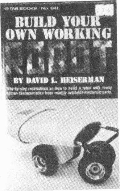
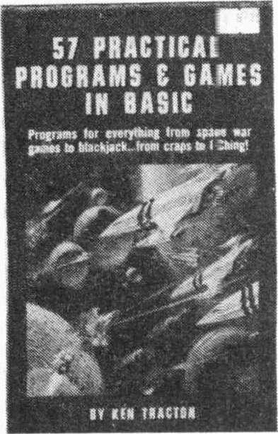
67 4 TABTABTABTABTABTABTABTABTABTABTABTABTABI'ÁBTABTABTABTABTABTABTABTRBTABTABTABTABT NOW! Electronics Today is now offering this fine set of exciting electronics books from TAB! Tab Books From ETI LBTABTABTABTABTABTABTABTABTABTABTABTABTABTABTABTABTABTABTABTABTABTABTABTABTABTAB. *Order by number using handy card in this issue! * HOW TO DESIGN. RAID. & TEST COMPLETE SPEAKER SYSTEMS d rngdro dgir-yegmw uw MlhrioweMelwle BeIME The Complete Handbook Of RObOtiCS ial 111te in(?ill'k!.mw.+.y machines "think" x - v,e; -T-... 'gialldaeays.w rn A BEGINNER SAKIDE TO COMPUTE MICROPROCES *Oh pro " O ev Eddwaa0 L SafEM0. it 1064 $ $ $ $ $ =$ $ =$9.25 w.da w:os b. TMoMo«wens and +mooed Thr.a 1 am 51 PRACTICAL PROGRAMS C GAMES IN BASIC hymns s ter eaerpwat im p, apaee ear peo le»dock.. how craps M 1 Srpp BY 6AYI0 I. Nfl8áR11At1 de' M...m maniawer.l..wati ; Now to Design C. Your Own Custom TV Games r- L rtr / by Oovi6l: Wakeman 100C $ = $ =$8.10 $ =$ $ =$13.30 e.eeaonc.w eg. Master 1001 Handbook of Practical Electronic Circuits Edited by Kendall Webster Sessions A comprehensive collection of 1001 meowed curl and Iranslslur ennuis with all the dala sneeded lo but them le rood: Alarms -Audio.. Amplrllers Aulomnlive- Fillers- Gown-- Counlers & Cloths -Power Strophes -Volley RE Murhphers-_Receivers Preampldrers & Conversers- Regulators- Re Generators & Waveshapers-Rf Power Amplrllers-lest Egwpme,l--Control & tone Cliewls-Carrier Operated Relays and Other Repealer Crrcwlstimers- Transmitters Transceivers Enders & VFO Crrawls- Battery Chargers -Diode Cntuds,-Mrseellaneous Comfits Master 1001 Handbook of MORE Practical Electronic Circuits Edited by Michael L. fair ur.nrnwn it _ - _ nr 1088 $ =$ $ =$ $ =$16.90 Prices shown are cover price plus postage and packing. As you can see from the postage, many of these books are heavies! ETI CANADA -DECEMBER $ =$


 the Triac opens, but will close again almost instantaneously if retriggered.")

68 Practical Guide To Triacs Part Part 1 -Switching circuits o J Fig. 1. Construction and electrical connections of typical Triacs. ELECTRONICS, according to a friend of ours, is anything electrical that he doesn't use or understand. Triacs, by this definition, must soon be considered non -electronic, for they are finding ever-increasing use throughout electrical engineering - in both consumer and industrial applications. In effect, a Triac is similar to a latching relay. It closes - practically instantaneously - after being triggered, and remains closed until the supply voltage is reduced to zero (or changes polarity). When this occurs (twice every complete cycle if used on ac) the Triac opens, but will close again almost instantaneously if retriggered. STATIC SWITCHING Triacs can usefully replace mechanical switches in ac circuits. They allow the control of relatively high power by very low triggering current - and as Triacs latch each half -cycle there is no contact bounce; nor, as they open only at current zero, is any arcing or transient voltage developed due to stored inductive energy in the load or power lines. They eliminate completely the contact sticking and wear associated with electro -mechanical relay, contactors, etc Triggering arrangements are very flexible - most Triacs can be switched into conduction at any point on either half -cycle of the ac waveform by applying a low voltage of either polarity between the gate electrode and anode I. (A few types of Triac can only be switched by a negative -going gate voltage or pulse.) The triggering voltage can be obtained from a battery (Fig. 2) or simply from the ac mains (Fig. 3). In either case, full wave current will flow Fig. 2 Triac triggered by external dc voltage. Fig. 3. Triac is triggered by input ac, in this application switch S1 will be 'live'. Triacs are simple, versatile devices used throughout electrical and electronic engineering. Yet most electricians regard them with almost superstitious awe. This three-part article describes their uses in a totally practical way. when SI is closed and current will cease to flow at the end of the half -cycle (whether positive or negative) in which SI is opened (Fig. 4). ELIMINATES BURNT CONTACTS The simplest possible method of triggering is shown in Fig. 3. This circuit is often used to eliminate burnt contact breaker points in thermostats and similar devices which have to Fig. 4. A triac can be triggered into conduction at any point along the sine -wave, but will only switch off at current zero. make and break large currents at frequent intervals. The existing make and break arrangement is retained but used only to switch the Triac, which in turn switches the main load current. The current flowing through the contacts is reduced to a few milliamps. MOVEMENT SWITCHES TRIAC A magnetic method of triggering may be used when a mechanical movement actuates an electrical circuit. To do this, a magnetically operated reed switch is used as SI. The switch contacts are closed when a magnet is brought near the switch. The actual distance will depend upon the sensitivity of the reed switch and the strength of the magnet ('/2" to 1" is typical). Various applications of this principle are shown in Fig. 5. ETI CANADA-DECEMBER 1979

.")


69 Practical Guide To Triacs Part I Magnetic reed switch used for How control minimises restraint on moving parts and avoids perforating tube wall. Reed switch simplifies positional control. O--1 LOAD AC Fig. 5. A magnetically operated reed switch provides electrically isolated triggering from mechanical movement. The switch will close when the magnet is brought within half an inch or so. Suggested applications are shown in Figs 5a, 5b and 5c. o -- Reed switches may also be used to provide electrical isolation between the Triac and the triggering circuit. The reed is inserted in a coil which is then switched by a suitable low voltage dc supply (Fig. 6). As the life of reed switches exceeds several millior operations, this is an extremely reliable method of switching. Other simple methods used to isolate the triggering circuit from the Triac are shown in Figs. 7 and 8. The photo -cell coupling shown in Fig. 8 provides extremely high electrical isolation. Photo -cell couplers, in which a light source and photo -cell are integrally mounted, are commercially available for as little as a dollar. An unusual off/half-power/ full -power circuit is shown in Fig. 9. When half -power is required, the diode is switched in series with the triggering lead. This causes the Triac to conduct only on alternate half -cycles. The circuit is suitable for heating, or other resistive loads that have thermal inertia. It is not suitable for lighting control, as the halved frequency will cause an irritating flicker; nor should it be used for inductive loads such as motors or transformers. A latching circuit is shown in Fig. 10. Momentarily depressing SI will cause the Triac to conduct and to remain ETl CANADA-DECEMBER 1979 Liquid level control. o Fig. 6. Reed relay can be electrically operated ro provide electrical isolation. Fig. 7. Isolated ac provides triggering. conducting after SI is released. The circuit is reset by momentarily depressing S2. Cl should be a 0.5 pf to 2.0 pf, 630 volt working, non -polarised capacitor. TIME DELAY CIRCUITS Triac time delay circuits are shown in Figs. 11, 12 and 13. All three circuits will provide time delays up to 100 seconds or so and may be used for applications such as photographic timers, industrial machinery, etc. In the circuit shown in Fig. 11 the Triac will conduct as soon as SI is closed. After a time - determined by the setting of the one Megohm potentiometer -- the unijunction will fire, causing SCR1 to conduct thus removing the triggering voltage from the Triac. Another version of this time delay circuit is shown in Fig. 12. A different type of time delay circuit is shown in Fig. 13. In this circuit the Triac will conduct after SI is closed. The time interval is set by the one Megohm potentiometer. Liquid level is used to switch the Triac circuit in Fig. 14. The Triac will conduct when the resistance between the sensing probes falls below 100K. The pulse transformer in this circuit must be well insulated to ensure that 69
70 Fig. 10. This triggering circuit provides latching action. Fig. 11. Time delay circuit - power is disconnected from load after pre-set time. Fig. 13. Time delay circuit - power is connected to load at end of pre-set delay. Fig. 8. Photo -cell coupling provides electrical isolation. o -- Fig. 9. Circuit can be switched to provide half or full power into load. AC IOfyi 100, 10K, S.a.i,00 LOAD o Fig. 12. Time delay circuit - action similar to Fig PROBES Fig. 15. Capacitor and resistor should be connected across the Triac when. switching inductive loads. Fig. 14. Liquid level switch. Triac is switched when liquid covers probes. Triacs Part I line voltage cannot appear across the probes. INDUCTIVE LOADS Ad the circuits described so far will operate reliably with resistive loads. Inductive loads present a minor problem. For reliable operation it may be necessary to limit the rate of voltage rise immediately following turn-off. This is done by connecting a capacitor and series resistor across the Triac (Fig. 15). A Triac's power rating is a function of its operating temperature. Thus a unit of 6 amps nominal rating used without a heat -sink must be derated to 11/2 amps. A rough guide can be obtained from the Triac's external case temperature. This should not exceed C. In the majority of circuits the outer case of a Triac will be 'live'. Because of this it is necessary either to insulate the heat -sink from surrounding metalwork, or to insulate the Triac from the heat -sink. Two flat mica washers and a Teflon collar will effectively insulate the Triac from the heat -sink, but there will be an appreciable loss in cooling efficiency. Where possible, it is better to have metal -to -metal contact and then to use an insulated mounting for the heat -sink itself. Providing Triacs have adequate heat -sinks, it is permissible to run them permanently at their maximum designed rating. They can also withstand considerable overloads for short periods. A typical unit can withstand ten times its nominal rating for one half -cycle of a 50 Hz waveform. DO NOT OVERLOAD Despite this tolerance of short-term overloads, Triacs must not exceed their designed ratings for more than a fraction of a second. A short circuit will destroy them instantaneously. Fusing is usually ineffective, as a Triac will almost invariable fail first and protect the fuse. An almost certain symptom of overloading is loss of gate control; the Triac will appear to have a short circuit from one anode to the other, although overloaded Triacs will occasionally still operate on one half -cycle only. The second part of this article - to be published next month - describes the use of Triacs in power control, covering both zero voltage switching and phase control circuits.


, and there is an air of hopefulness.")


71 WHAT S ON Dial Steve Rimmer for info on flat TV, satellite TV, and the latest non -word on video discs. NEW FALL SHOWS IT TAKES ABOUT A DAY to think up one of these literary gems, three hours to type it, thirty minutes to proofread it, a few days to get up the energy to take it out to be retyped so as to be readable and probably an hour to get it down to ETI's offices in the 'urbs. After that, something happens to it foraboutthree months... God only knows what; ;they don't like to talk about that part. One suggestion is that the editors have to wait for the next equinox before putting together the magazine... toavoid being hexed. (Nobody likes to read a magazine that's always sprouting eyes at you, after all). The result of this delay is that there is something of a ti me warp about me; you are probably convinced that it'scoming in December, while I am under a delusion of mid -September. The new fall shows have just sprung up, rather like hallucinogenic mushrooms that don't make you see anything. We have now been through one full week of A Man Called Sloane, The New Archie Bunker and Out of the Blue (And Under A Rock), and there is an air of hopefulness... that the mid -season replacements will be an improvement. But, you see, you already know this, existing as you do, some months in the future. You already know that all this hope was in vain. Since what is on the tube is. generally, going down one, perhaps the time has come to turn our attention to the tube, itself. It is certainly more interesting to operate a push button tuner than to watch a spin off of a spin out, so this month we're going to have a look at some of the freaky new tubes developing this fall. Each one guaranteed to outlast 95% of the current schedule. Fig. 1 Sharp's prototype flat TV set featuring their 'Electroluminescence Panel' FLATBACK TV The device in figure 1 is the first production prototype of Sharp's solid state TV. That. on the surface, doesn't sound all that wonderful because manufacturers have been plugging solid state sets for years. However, if you think about it, as it stands now, an all solid state TV is impossible because of that one, rather obnoxious, tube that keeps staring out at you: the CRT. While all around it has gone from nine pin glass to three pin silicon, it has remained. a flickering blue mastodon, some fifty years behind the times. Now considerably larger than its support circuitry. it isthesoledeterminateof the size of a TV set, as well as accounting, directly or indirectly, for about half the parts count and a good three quarters of the power consumption. It's also expensive, unstable, delicate and, in the end. rather transitory. Since the mid -fifties. there have been numerous attempts at being rid of it. While by no meansthefirst, the Sharp set seems to be the closest toward getting into production. At present, there are only five working models in existence, but the fact is that they are working. Within a few years, the tooling up procedure for turning the beastie out in quantity will have been completed and the things will be available at the local stereo emporium. While as much a harbinger of things to come as a revolution in itself, this "flat screen" set a very, very interesting bit of is hardware. The specs of the set are the first, and probably the most amusing thing to catch the eye. You can almost see the ads in Time and Playboy. The whole works is two inches thick. It weighs about eight and a half pound. less than the power transformer on a twelve inch, CRT type set. It has a 50:1 contrast ration and a thirty gradation grey scale. It runs on nine watts of power; about twice as much as used by the heaterina conventional CRT. Its parts count is less than that of a transistor radio. It has none of the conventional adjustments... horizontal linearity, vertical size, etc... associated with a not quite solid state TV. It will eventually probably sell for less than even a super bargain type "Ask Me No Questions" brand set peddles for today. It's a gas, but. with no tubes, it actually contains none. The heart of the device is, of course, what it uses as a "picture tube". Sharp doesn't get all that descriptive about what this actually is. It's called an "Electroluminescence Panel". The description reads as follows: "It's a super flat display with an incredibly sharp picture that's created by pulses that alternatingly polarize and depolarize electrodes built into the screen". Now this sounds somewhat familiar. Rather like a liquid crystal display. HISTORICAL PERSPECTIVE There have been, traditionally, three approaches to flat screen TV. These ETI CANADA -DECEMBER
72 are: the phosphorescent dot method, the gas discharge method and the LCD. The first trip involved a matrix of lines with a potentially luminous dot at each intersection (later replaced by a self - scanning, charge coupled affair in some conceptions), wherein, when it came time for a dot to be excited, it got zapped with pulses on the corresponding lines (or by the appropriate charge coupled element). It had the advantage that, simply by overlaying three matricies. a full colour display could be arrived at, just as a colour picture tube comes about by having three guns and three sets of phosphor dots. The difficulty arose in the nature of phosphor. It is not all that efficient a transducer of electrical energy to light. Fairly hefty pulses were required to activate the dots, and these sorts of voltages and currents do not sleep well alongside teeny, tiny wires and micromicrornicrotransistors. The second attack on the problem, the gas discharge array, came, as one might expect, from Burroughs, who have always seemed to maintain a fascination with neon lights. Essentially, it is simply a rnatrixed plasma -type display, with a flock of high voltage drivers. In a sense, this type of approach has already met with some success in other video applications, such as alpha -numeric readouts. Where it comes into difficulty is in handling the complexities of analog video. Neon bulbs tend to like being either on or off. and in between, are something less than linear. This calls for some sort of pulse width modulation technique, which also poses several problems. Here, too, high voltages get to be a hassle. Lastly, and probably most uncomfortably, neon lights are orange and, as radically banal as it looks now, the CBC would seem ten times worse through perpetually rosecoloured glasses. The third approach is the one which suggests itself when reading the description, however scanty, of the Sharp Electro -whatever. It uses a matrix of liquid crystal elements, LCDs, of the same sort as found in a digital watch or thin calculator. LCDs, unlike the previous two systems, don't give off any light. They are blobs of nematic fluid between transparently thin metal electrodes which can have their molecules polarized so as to make the stuff either opaque or transmissive. The "pulses" that switch them, at least in the case of the relatively low rate of change situations found in digital displays, are square waves at frequencies of thiry to fifty Hz. Any slower and the display flickers; any faster and it ignores the switching signal. This has been one of the stumbling blocks on the road to LCD video displays. You can't display a 4.5 Megahertz picture signal when the fastest available switching rate is less than the frequency of the vertical scan. The second problem is in that LCDs have been inherentlyslowto respond to a change of state; it takes time for the extremely large molecules of the nematic fluid to go scurrying around and find themselves a new orientation. LOOKING AHEAD If, in fact, a practical display has been arrived at, the possibilities are many. For one thing, wall -sized pictures are possible without the need for the behemoth Advent video projectors that cropped up a few years back. At the other end of the scale, one could put a set in a case the size of a pack of smokes or even a wristwatch. (Yes! That's the answer. We can't cancel Mork and Mindy, so we'll just shrink it down to the size where it can't be seen anymore.) Inside of ten years, you may not sit down in front of the family tube, but rather, just drop it into your eye, like a contact lens. The flat screen TV has been approaching from another direction as well. While it has seemed like the semiconductor screen was really quite a pie in the sky, for a long time now designers have been having varying degrees of success at making a flatter cathode ray tube. First of all, of course, it went from the 700 post oscilloscope tube to the 900 and later 110 affairsthat eventually eradicated the sets that were bigger in the depth dimensions than in frontal area. However, there was also a lot of back room thought given to coming up with a radically different sort of CRT. Envisioned as being about the. size and shape of a paperback novel, the new tube would fire its beam down the long dimension of the shell, instead of front to back, bending them atthe last moment to strike a screen on one of the large faces of the tube. In one version of the project, which emerged in 1965, there were two screens and the thing could be watched, simultaneously, from both sides. It had several disadvantages, though, not the least of which was that it didn't really work. This, was only a major problem when you turned on the set. At all other times it really wasn't a bad design at all. You have probably seen ads for the itty bitty pocket TV built by the British firm, Sinclair. While this set, in itself, embodies no new technological breakthroughs, it does foretell a few, for it seems that Sinclair feels that the watchword for the future of the groove tube is small. Thus, the bent beam CRT has recently re-emerged across the water and, this time around, with somewhat more success. A pocket go - anywhere portable "mind rot" is expected to be on the market using it, presumably superceding Sinclair's present small set, in a couple of years. Just think, you need never miss another commercial YY Fig. 2a Schematic representation of Sinclair flat picture tube. As can be seen from the diagram, which should be around here somewhere, the tube is not one of the more complex devices. A beam skids down the thing and hits a screen. Very simple. Except that, as you might think, if a beam of circular cross section intersects a plane at something other than a right angle, the resulting shape of the area of intersection will be elliptical, not round. This would produce a picture having many ofthecharacteristicsofan Olde English Sheepdog lying on a rug during shedding season. Unless you're a real animal lover, this may not do you in. Fig. 2b Physical construction of Sinclair flat pictu,e tube. Therefore, some fairly heavy magnetic acrobatics are required to allow the beam to proceed as if it were going for the end of the tube, instead of the side, and then deflect it so it winds up in the proper portion of the screen. This is done by placing a metal electrode on the face of the tube opposite to the screen and making it extremely negative, thus repelling the beams. (This, of course, is only one of the possible approaches. A photo of Joe Who, for example, pasted to the inside of the tube, would turn away all but the most conservative electrons and they could probably be sent on their 72 ETI CANADA-DECEMBER 1979
73 collective way by nothing more than a few threats.) Now there are still a few problems. First of all, unlike in a regular TV. you don't look at the phosphor screen from the back. You view the same surface as the electron beam strikes, simply because it's brighter. However, back a paragraph or two ago. we seem to have covered over the window through which it is supposed to be viewed with a nasty, large metal electrode.therefore, we must take the metal away, or, at least. most of it. What, in fact, comprises the deflecting electrode in a practical tube is a very thin metallic deposit, so thin that it is transparent Curiously, this is essentially the same way that electrodes are formed in the liquid crystal displays back with the Sharp set. The other difficulty is in getting the picture to come out with straight sides. Yes, we seem to have a problem here. Remember that a deflected electron beam forms a triangle, with the apex at the cathode. This doesn't make a great deal of difference when the beam is directed at a perpendicular screen, but this one is parallel to it. In other words, the bottom of the screen, closest to the gun, will not be covered with as wide a swath of electrons as the top, which is further away. In order to get around this, it is necessary to make the horizonal deflection voltage a function of the vertical deflection, such that, as the beam gets closer to the bottom the horizontal deflection plates receive an increasingly higher voltage. In effect, what is required is that the horizontal signal be modulated with the vertical, at a small index of modulation, of course, lest the effect of the varying width be reversed. The pocket CRT has many advantages. It is simple, light, cheap and uses much lower voltages than its larger ancestors, while it showed promise in manyof the areas being aimed at by the developers of the solid state screen,it has the one big feature that you'll probably, be able to go out and buy one in only a few years and, probably for a great deal less than the initial amount all solid state sets will cost. The real beauty of something like this is that, as Clive Sinclair probably realizes all too well, little TVs are cute. They sell well, so they can be mass produced. Therefore, they're cheap. So they sell well and you can mass produce some more. This, of course, is a self-defeating process, especially if you're a yet -to - be -manufactured TV set. Sooner or later, the fellow who's buy mass producing all these sets, mass produces enough to retire to Jamaica. DEFLECTION ANGLE AT TOP DEFLECTION ANGLE AT BOTTOM Fig. 2c Top view of Sinclair flat picture tube showing different deflection angles. MORE ON SATELLITES Lastly, I think that it is about time to gather together all the bits and pieces of satellite information that have accumulated since the appearance of the bit on satellite TV in August. There have been a number of letters which, after clearing them with the cat to make sure that they weren't edible (the cat usually gets to my mail before I do and checks out anything that looks like it might render a decent snack), I have discovered to contain vast wealths of information on such things as where to find receiver plans and a possible future source of very cheap TVRO ground stations. As well, I have come across a few good bits, myself. The cat, for the most part, has been of questionable value in the project. Cats, in general, have relatively little aptitude for high frequency electronics.. First of all, a Mr. Douglas Orlowski.. the Mr. Douglas Orlowski, if you know him... has come up with a rather good list of sources of information for TVRO terminals. I wouldn't suggest sending for all of it; this could get a mite expensive and, besides which, there is considerable overlapping between authors. However, any one of these packages should be sufficient to get you going. What's On 1. First, there is the Community Access Television Journal, which is actually the publication that got me started in this stuff, about a year ago. They have a large package of assorted material available for sixteen bucks, plus four tapes dealing with building you own downlink, at $50 each for Beta or $55 for VHS. They reside under the flag of Television Publications, Inc., Suite 106, 4209 NW 23rd, Oklahoma City. Ok There is a booklet put out by Space Coast Research, Box 442, Altamonte, Fla , on how to receive satellite TV. It goes for $ Bill Weaver, Box 852, Tulsa, Oklahoma , has a booklet on setting up a downlink for $3.00. (The book is $3.00; the downlink will probably run slightly higher.) 4. For three dollars more you can have another book from Satellite Television. Box 140, Oxford, New York You can guess what it's about. 5. Wireless World's June and July issues have a bit on building a weather satellite downlink, with some fairly good circuitry and a number of very clever design innovations. There would be some retuning and such required to use this as a television satellite downlink, but this should not be excessively difficult. 6. A bit of literature from Tape Time, Box G, Arcadia, Oklahoma , appeared beneath the cat a few weeks ago, dealing with the availability of cassettes of both satellite downlink constructional details and magazine - type looks at the material offered via satellite. The list is a bit long, so I'd suggest writing for a copy yourself. Another reader... I shall apologize here for not knowing who; the cat did get at this one... brought up the most interesting issue of the attempts presently being made to have Canada sell Australia a satellite communication system. If this were, in fact, to come about, TVRO sets would be mass produced here, bringing the cost down to around.. gadzooks; $800.00! If you have been following the politics involved in this, you will know that this situation is still a very open question (although it may no longer be by the time this column reaches print), but this would certainly be a great step forward both for Canadian industry and the myriad great unwashed victims of the CBC. A few other readers have written in suggesting that the prices suggested in the satellite piece were pessimistically high. In fact, fora bona fide, off the shelf ground station, the prices were about ETI CANADA-DECEMBER


74 .. are don't What's On right. While the figures that the American magazines are quoting now and then... i.e., that a fellow in California got one going for about a grand. a hit unrealistic for an average technical gnome with average equipment, there are, definitely, shortcuts. One of these is the Robert Coleman terminal, which comes by the electronics of the system for about two to three hundred dollars. We'll have a look at that one as soon as I can find out how he does it. There is also a bit of additional information dealing with the October cable TV column. The other day, I came across a list of the frequencies at which the cable converter channels are located. For those interested in homemade converters, table 1 lists them.. which should save a bit of coaxial DXing. Among the mail there have been several requests for information about specific video hardware. So far, I've been able to answer them, but it did occure to me, during a moment of no great import, that there may be quite a number of loose bits of gear out there in search of schematics, manuals or odd parts. If you are using one of these as a coffee table or paperweight, and could use a hand, place your fingers upon your typewriter. Address any requests, queries or Himalayan Cactus chants to this column and we'll print them, so that some other interested reader with a similar piece of furniture, but more documentation, can assist you through the wonders of return mail and xerox. To get things started, I've decided to toss out one of my own. The.. ahem... THING below issome sort of keyboard. I know not what sort. nor what hand claims responsibility for its creation, as it bears not a single marking. Anybody who has any ideas is requested to contact me here. (This Anybody recognizing this poor waif should immediately send identifying data to the Steve Rimmer Home for Wayward Keyboards. TABLE 1 Cable Converter Frequencies These are the actual frequencies that come down the cable, to be beat down to channel 3 by a home converter. The frequencies given are lower channel limits; add 1.25 MHz to get the sound carrier frequency, and 5.75 MHz for video. Converter channel Frequency Converter channel Frequency Midband High Band A 120 J 216 B 126 K 222 C 132 L 228 D 138 M 234 E 144 N 240 F 150 O 246 G 156 P 252 H 162 O R 264 wretched beast is eventually supposed to be part of a video charactergenerator which should appear herein some time next year, if I blow any more chips). This being just about the end of the column, I should take this opportunity to thank eternal fiend and temporal munchkin Levi Usher for the pages he stole from the July 19, 1979 issue of Electronics Magazine, on my behalf,.. I don't know who owned the copy in question. outlining the Sinclair flat TV tube; the tiny grain of data (well, two pages, actually) that sent me off looking for more and better insight to this marvellous creation, but! won't. NEXT MONTH NO VIDEO DISCS Next month... I don't know what's going to happen. I think that I can safely say that we will not be having a look at video discs. By this time, anybody who hasn't read quite enough about the Phillips/Magnavision system has probably been dead fortwo years, and RCA hasn't really said a whole lot about theirs as of yet. Works in progress are a complete set of instructions for making an Ampex VP video player into an Ampex VR-5000 video recorder, and a look at an IC that generates all the complex nasties of TV sync pulsery. However, I hooked the power up backwards to the one I've got, so the appearance of the feature will be dependent upon whether or not the 'post office' arrives with a new one in time. Until next month... stay tuned. 7 rttropocarlq -14É 415graQllz119[ --rne. "r.j N431.F,r1c T 4 a * * 11 1A # i1cpntiin os1oaaaiar;r` > i! i I111 fll* * itllílli cfr CaKtsE, (Nb f.tltkaa Mtckoy,pPE HAt Gs1A8tk.s (a "ío sff JHAt'S a! 114 sck4.tr) \S a-1 opt1o,410- SiR 74 ETI CANADA -DECEMBER 1979


75 Fluorescent Displays Conventional moving -coil meters on hill equipment are being supplanted by fluorescent bar -graph displays on this year's new releases -- here's the 'inside' story. OUR ATTENTION was drawn to this trend in audio equipment design by a recent release from National Technics. Their two latest front -loading stereo cassette decks, the RS -M22 and RS -M33, feature these new displays, replacing conventional twin moving -coil VU meters common on this type of equipment to date. Compared to a conventional meter, National claim the fluorescent bar - graph display has the following advantages: fast response time no overshoot excellent accuracy high reliability A minimum response time of 5 us is typical, according to the Technics release, and accuracy is within +/- 0.1 db at 0 scale and within +/- 0.5 db across the rest of the scale. As the display uses digital techniques for its operation, response time may be selected for both 'peak' and 'VU' scale reading. The construction ensures a rugged display device with a lifetime specified at hours and greater resistance to shock than a moving -coil meter. A cutaway, exploded view of portion of the fluorescent display showing the internal construction and the special fluorescent anodes. The device body is a flat vacuum tube sandwiching a filament, grid and anode elements between a glass base and moulded glass front panel which has a transparent conductive film on the under surface. The filament is heated by passing a current through it, causing it to emit electrons. These are attracted to the anodes, passing through the control grid. When electrons strike the anodes they fluoresce, emitting light. There are no moving parts and control is enitrely electronic resulting in Technics' M22 stereo cassette deck featuring a fluorescent bar -graph VU/peak meter. Front Glass Transparent Conductive Film Grid Anode Segment (' : Anode Base Lead Wire an extremely fast response time. The anode shape is designed for easy viewing and a number of parameters can be seen at a glance - both peak and VU indications are available at the one time on the Technics display. As the display emits light it can be easily read and interpreted from a distance. Brightness can be varied, either under manual or electronic control. The left and right hand channel displays are aligned in parallel allowing instant comparison. The levels above 0 VU are displayed as rectangles with bright edges, whereas levels below this point are indicated by solid bright squares resulting in a display that can be interpreted at a glance. The scale is divided into 12 steps between -20 db and +8 db with finer divisions around the 0 VU area. A newly developed monolithic IC drives the display and, since a full -wave rectifier circuit is used, the display will produce an accurate indication even when presented with an asymmetrical waveform. It seems inevitable that these flourescent bar -graph displays will enjoy wide success in both the consumer and professional audio equipment market. ETI CANADA-DECEMBER


76 Teachers' o iss ETI Canada's Editor, Graham Wideman, has some handy notes, and strong feelings on how circuit diagrams should be drawn. I AM GO!NG to talk about drawing circuit diagrams. Not how to read them, or what the symbols mean, but about arranging the drawing itself. For some reason this is a function which is executed by many people in a "you don't talk about it, you just do it" manner. But drawing a circuit diagram is not simply the combining of appropriate symbols. The diagram should not merely be the sum of the symbols. And it should not be done by starting off in one corner of the page, blackboard or napkin, and adding symbols until it is complete. The circuit diagram exists to educate the diagram reader, or even the person who drew it, as to how the circuit works, and hence benefits greatly from an arrangement which makes it easy to understand. SO HOW DO YOU DO IT? I have seen many styles of diagrams, many sets of symbols, and many "rules" for drawing diagrams. What I feel is needed, is a set of rules which are easy to apply or modify for any situation you come across, and which must be easy to remember, and "feel right". Symbols used should be either standard, or selected from those commonly used, and "look like" the thing they are intended to represent, again for ease of recognition and remembering. What I have thus attempted to do below, is come up with a set of suggestions which I feel formally describes a way of drawing diagrams that has helped me understand, but more importantly quickly communicates to others what a circuit is all about. WHAT IS A CIRCUIT DIAGRAM INTENDED TO SHOW? (a) The entire raison-d'etre for the circuit itself, is to do something to a signal, or signals. Thus it can be said 76 that a circuit may have a signal input(s), and always has outputs. It follows that one very important feature of the circuit diagram is to show how the signal(s) travels through the circuit. (b) The circuit diagram must also show what happens to the signal in each "stage" of the circuit, and hence also show how each stage works. (c) The circuit diagram layout should not be influenced by the physical layout of parts, unless this is convenient and does not interfere with ease of understanding of (a) and (b) above. HOW DO WE ACHIEVE THESE? 1/ Adopt a convention of having signals travel from left to right on the diagram, inputs on the left, outputs on the right. 2/ Adopt a convention of drawing individual stages so that current flows down from top to bottom, or that voltage decreases when you go down the diagram. This one is a little hard to visualize, but basically it's just a scheme for orienting components in a way which shows how they work in the "DC Analysis", or no signal condition. Particular examples are: putting the + supply at the top and the - supply at the bottom; orienting a collector resistor for a common emitter amplifier vertically, but orienting an inter -stage signal carrying resistor horizontally. It sounds tedious, but it falls into place in practice. 3/ Do not show all the power supply and ground points in the circuit connected to each other. Instead, anywhere a component is to be connected to a power supply or ground, draw in the symbols for power supply or ground. The reason for this is to reduce the clutter of lines on the drawing, and to only show lines which carry signals around. This last point is very important. If power supply and ground lines are shown, then it is not necessarily clear from cursory inspection how the signal gets from input to output for example. If no supply lines are shown, it is very obvious what the signal path is, since it is the only path from beginning to end, and the only path between stages. SIDE BENEFIT An additional bonus of following the above three rules, is that it tends to make the same circuit electronic configuration appear the same from drawing to drawing. This makes it easy to recognize circuits (or parts there of) with which one is already familiar. It helps one to think in terms of circuit function blocks, rather than individual components. SYMBOLS Before we actually get into a few examples, we have to establish some symbols for power supplies and ground. Here we are talking about hand written symbols particularly. The factors to consider are convenience of use, and if possible the selection of symbols which somehow look like their meaning. POWER SUPPLY SYMBOL The two commonly used symbols for a power supply connection are the arrow and the line: t1ov +10V or Personally, I prefer the line for several reasons. It is a horizontal line on a drawing where we said "going down the page" is like decreasing voltage, thus it says "constant voltage". Secondly the symbol can be approached from both sides, such as: ov /W -t- SV Easy Difficult GROUND SYMBOL tjsv Probably the most used symbol for ground is: 1 However this has a disadvantage, which is that it looks odd at other angles, and ETI CANADA-DECEMBER 1979
 : T\"V This is not bad, and is sometimes seen on schematics, but there's a \"nicer\" symbol even than this.")


77 _ óii is thus difficult to approach from the sides or especially below: T?...r,, Or Pr- So why not use our power supply symbol for ground also, labelled OV (zero volts) : T"V This is not bad, and is sometimes seen on schematics, but there's a "nicer" symbol even than this. The problem with the: 1" symbol is that it requires writing out "0V" everytime, which aside from being extra work, is easy to misread. How about the occasionally used: --~1~-y( I as our ground symbol? You can connect to it from all four sides, it doesn't require a written note, but does it "look like zero"? Yes, if you think of it in a 3 -dimensional way, such as it looks like the "origin" of three coordinate space. NOW you can look at the examples! CONCLUSIONS: Systems such as the one I've just outlined, combine convenient notation, and a few straightforward rules. You will probably find that using this drawing technique you tend to start drawing with the active parts, transistors and tubes, and "growing" the resistors, capacitors etc. around them. This is an effective way of thinking about the circuit, and whether you adopt this, or a similar scheme, after a few uses it becomes easier to draw a schematic this way than in any other arrangement. It has been found useful in initially drawing a design.,"transcribing" someone elses design into an understandable form, and aids in explaining the circuit operation to other people. IN COuT T LEVEL,p;_ADJ PHASE SHIFT OSCILLATOR ' eiz43 zzna `iizoó f üccr A00 zzoo o `noo. too o SW 301 Qsww, `.ói1 IIoo " 0,5 t Fig. 1. Maybe the battery is arm wrestling? (By the way, all the "before" diagrams were either taken from, or copied from very respected sources. We promise not to say who they are unless they complain.) Fig. 2. A true bonanza of extra lines. What is it? After: Obviously a common emitter amp, very simple. INo,. - e After: Guess what? It's a common emitter amp with a feedback loop ie: an oscillator. And a common collector amp to follow it up. + 30V (RÁÍ' tbrrl ve Fig. 3. A ten watt audio amp design. Try to follow the routes that signals take through this circuit. put After: Redrawn the ONLY wires shown joining transistors are those r carrying signals. With very little expertise it's easy to spot the route forwards through the amplifier, and the two feedback paths. ETI CANADA-DECEMBER


78 The FUfl0f Electronics HMM, THERE'S NO SIGNAL ON THE ELECTRO- CARDIOGRAPH... EITHER THE BATTERIES ARE DEAD OR YOU ARE. CALCULATOR C EN TR E AND THIS IS ONE OF THE NEW "BEEP -- TO -THE -TOUCH" CALCULATORS. IT COMES COMPLETE WITH A SUPPLY OF TRANQUILIZER PILLS THAT YOU CAN DISTRIBUTE TO ANYONE WHO HAS TO BE NEARBY WHEN YOU USE THE CALCULATOR. JENKINS, I THINK PREAMPLIFIER" OF PERHAPS WE OUGHT HOW THE INDUSTRY ACRONYM THIS "COMBINED RECEIVER AND YOURS IS A GREAT INVENTION, BUT TO GIVE IT A BETTER NAME; YOU KNOW IS ONCE IT GETS HOLD OF A CATCHY THIS IS THE TOUGHEST LESSON SO FAR IN MY TELEVISIO REPAIR CORRESPONDENCE COURSE; IT'S ENTITLED "HOW TO KEEP A STRAIGHT FACE WHEN PRESENTING YOUR BILL TO THE CUSTOMER-. óaaeg WHEN YOU SOLD THIS TO ME LAST WEEK, YOU SAID IT WAS A "PRECISION DESOLDERING KIT'" I DO NOT CONSIDER A TORCH AND A PAIR OF PLIERS AS A "PRECISION DESOLDERING KIT." 78 ETI CANADA -DECEMBER 1979
 you can promote your business from coast to coast. WHAT DO YOU DO?")
.")
 will see it in the January issue PRINTED circuit boards and kits from stock. No. 470-$5.45; No. 541-$2.95; No.")


 579-0536. Write for giant catalog, free of course!")


79 J3f3útitwottl ETI's new classified advertising section allows you to reach 30,000 readers nation-wide. For as little as $15 (there's a 20 word minimum) you can promote your business from coast to coast. WHAT DO YOU DO? Send us your typewritten or clearly printed words, your permanent address and telephone number, and your money (no cash please). Make your cheque or money order payable to 'ETI Magazine'. We're at Unit 6, 25 Overlea Blvd., Toronto, Ontario M4H 1B1. WHAT DO WE DO? We typeset your words (and put the first word and your company name in bold capital letters). If we get your message by the 14th of the month, it will appear in ETI 11/2 months later. For example, if we receive it by November 14th, you (and thousands more) will see it in the January issue PRINTED circuit boards and kits from stock. No. 470-$5.45; No. 541-$2.95; No. 594-$1.75; No.141-$7.25; No.144$8.05; No.254-$2.10. Kits 591K U/D Counter c/w PCB $35.95; 490K Audio Comp. c/w PCB $ Terms:- Cheque, or Money with order NO COD.. P&P 50. Send for full list. B&R ELECTRONICS, Box 6326F, Hamilton, Ontario L9C 6L9. TRANSLATION SERVICES, D.L. Bousquet. Specialist in technical translations. Special rates and services for companies. For more info and free quotes, write or call: D.L. BOUSQUET, 50 Quebec Ave. Suite 404, Toronto, Ontario, M6P 4B4 (416) CLASSIFIED J&J ELECTRONICS LTD., P.O. Box , Winnipeg, Manitoba R3C 2Z4. Surplus Semiconductor Specialists. Do you get our bargain flyer? Send $1.00 to receive the current literature and specials and to be placed on the mailing list for future publications. CRYSTALS - All types monitor, marine, CB, amateur, professional, wholesale & retail. Write for information. K&K ELEC- TRONICS P.O. Box 3243,Hamilton L8H 7K6 NEW STORE! for the Hobbyist, Ham Audio, CB'r. Special: Video Camera and Monitor $ Ont res. add 7% sales tax. GENERAL ELECTRONICS, 5511 Yonge St., Willowdale, Ont WSI RADIO - SWL Radios - Ham radios - 18 Sheldon Avenue North, Kitchener, Ontario N2H 3M2. Telephone (519) Write for giant catalog, free of course!! (VE3EHC) PRINTED CIRCUIT boards from your sketch or artwork. Affordable prices. Also fun kit projects. Free details. DANOCINTHS INC. Dept. ETI, Box 261, Westland MI U.S.A. HOBBY Services. Novel construction plans, P.C. boards, complete kits and all associated services. Write for free information. TEKNIKIT Associates, 301 Flora St., Carleton Place, Ontario. K7C 3M8. SPECIAL!Surprise box containing 1000 electronic pieces for $10.00 or 3000 for $25.00, including capacitor - transistor - switches - wire - resistor - relay - hardware etc. All new parts, first quality. Money back guarantee. Flyer & sample on request. SURPLUS ELECTRO QUEB$C, 2264 Montee Gagnon, Blainville, Que ec, Canada. J7E 4H5 $1.00 Unusual Canadian and American parts and surplus catalogs. Hundreds of bargains. ETCO, Dept 087, 183G Hymus, Pointe Claire, Que. COMPONENTS; Digital and Analog IC's, Transistors, Diodes, Zeners, Resistors, LED's, Displays. Send for Free Price List. ELECTRONICS LONDON, Dept VII, Box 7096, London, Ontario. N5Y 4J9. SURPLUS 70K linear PC Board Mount Miniature Slide Pots 32mnr Travel Perfect for Graphic Equalizer Projects. 1-9 C' 80 each, ("' 75 each, 100 -up (ª? 70 each. Inquiries to: M.B. COMMUNICATIONS 188 Henderson Hwy. Wpg. Man. R2L 1L6 Ph TTY -TELETYPE Model 33ASR, paper tape reader/punch. ASCII 20mA serial interface, excellent condition, complete manuals. URI COGAN, R.R.2 Claremont, Ont. LOH 1E0. (416) MOTION detector, light level change sounds whoop alarm, LSI 14 pin DIP. $9.95 PPD. ELECTRONICS, Dept. ETI, Box 68, Whitecourt, AB. TOE 210 ETI CANADA --DECEMBER


80 ETI Project File PLEASE NOTE: WE CANNOT ANSWER PROJECT QUERIES BY TELEPHONE. Updates, news, information, ETI gives you project support PROJECT FILE is our department dealing with information regarding ETI Projects. Each month we will publish the Project Chart, any Project Notes which arise, general Project Constructor's Information, and some Reader's Letters and Questions relating to projects. PROJECT NOTES Since this magazine is largely put together by humans, the occasional error manages to slip by us into print. In addition variations in component characteristics and availability occur, and many readers write to us about their experiences in building our projects. This gives us information which could be helpful to other readers. Such information will be published in Project File under Project Notes. (Prior to May 78 it was to be found at the end of News Digest.! To find out If there are project notes for a project you are Interested In, simply refer to Project Chart (see below). If there are project notes listed, they will have appeared In Project File (note, prior to May 78, project notes appeared at the end of News Digest) Project notes can be ordered one of two ways. You can order the complete back issue, or you can order a photocopy from the ap- ISSUE DATE Dec 78 Aug 78 Aug 78 Aug 78 Sept 78 Nov 78 Sept 78 Nov 78 Sept 78 Oct 78 Nov 78 Oct 78 Nov 78 Sept 79 Oct 78 Apr 79 Nov 78 Nov 78 Nov 78 Dec 78 Feb 79 Mar 79 Dec 78 Feb 79 Dec 78 Feb '79 Jan 79 Feb 79 Jan 79 Feb 79 Jan 79 Feb 79 Feb 79 Feb 79 Feb 79 ARTICLE Note: N Porch Light & Neg. IB Metal Locater & Neg. Two Chip Siren & Neg. Audio Oscillator Neg. Shutter Timer Neg. Rain Alarm CCD Phaser Neg. UFO Detector Neg. C,D Strobe Idea Note: N Cap Meter &Neg. Stars & Dots CMOS Preamp & Neg. Digital Anemometer Neg Note:C. D Tape Noise Elim Neg EPROM Programmer Neg Log Exp Convert. Neg Digital Tach. Neg FM Transmitter Neg Phasemeter & Neg SW Radio Light Chaser & Neg priate Issue. In either case consult General Information For Readers. If you order a copy of a construction article, specify the Issue where the project note can be found and we will include the at no cost. You must spespecify from which Issue those project notes can be found. PROJECT CHART This chart is an index to all informatiog available relating to each project we have published in the preceding year. It guides you to where you will f ind the Article itself, and keeps you informed on any notes that come up on a particular project you are interested in. It also gives you an idea of the importance of the notes, in case youdo not havethe issue refered to on hand. Component Notations and Units We normally specify components using an international standard. Many readers will be unfamiliar with this but it'ssimple, less likely to lead to error and will be widely used sooner or later. ETI has opted for sooner! ISSUE DATE Mar 79 Mar 79 Apr 79 Apr 79 Apr 79 May 79 May 79 May 79 June 79 June 79 June 79 July 79 June 79 June 79 July 79 July 79 July 79 Aug 79 Aug 79 Aug 79 Sept 79 Sept 79 Sept 79 Sept 79 Oct 79 Oct 79 Oct 79 Oct 79 Nov 79 Nov 79 Nov 79 ARTICLE Tape -Slide Synch Synth. Sequ. Dual Dice Solar Control Audio Compressor Wheel of Fortune Light Controller AM Tuner VHF Ant. Easy Colour Organ LCD Thermometer Light Show Seq. Note C VHF Ant. 2 Bip Beacon STAC Timer Two Octave Organ Light Activ. Tacho Audio Power Meter Two Octave Organ Light Act Tacho. Field Strength Meter Sound Effects Unit Digital Wind Meter Up/Down Counter Simple Graphic Eq Digital Dial Variwiper Cable Tester 60W Amplifier Model Train Controller Curve Tracer Firstly decimal points are dropped and substituted with the multiplier. thus 4. 7 uf is written 4u7. Capacitors also use the multiplier nano (one nanofarad is 1000pF). Thus 0.1 uf is 100n, 5600pF is 5n6. Other examples are 5.6pF = 5p6, 0.5pF = Op5. Resistors are treated similarly: 1.8M ohms is 1M8, 56k ohms is 56k, 4.7k ohms is 4k7, 100 ohmsis 100R, 5.6 ohms is 5R6. Kits, PCBs, and Parts We do not supply parts for our projects, these must be obtained from component suppliers. However, in order to make things easier we cooperate with various companies to enable them to promptly supply kits, printed Circuit boards and unusual or hard -to -find parts. Prospective builders should consult the advertisements in ETI for suppliers for current and past projects. Any company interested in participating in the supply of kits, pcbs or parts should write to us on their letterhead for complete information. READER'S LETTERS AND QUESTIONS We obviously cannot troubleshootthe individual reader's projects, by letter or in person, so if you have a query we can only answer it to the extent of clearing up ambiguities, and providing Project Notes where appropriate. If you desire a reply to your letter it must be accompanied by a self addressed stamped envelope. ETI Project Chart PROJECT CHART This chart is an index to all information available relating to each project we have published in the preceding year. It guides you to where you will find the article itself, and keeps you informed on any notes that come up on a particular project you are interested in. It also gives you an idea of the importance of the notes, in case you do not have the issue refered to on hand. Canadian Projects Book Audio Limiter 5W Stereo Notes N, D May 79 Overfed Bass Enhancer Modular Disco G P Preamp Bel. Mic. Preamp Ceramic Cartridge Preamp Mixer & PSU VU Meter Circuit Headphone Amp 50W -100W Amp Note N May 79 Key to Project Notes C:- PCB or component layout D:- Circuit diagram N:- Parts Numbers, Specs Neg:- Negative of PCB pattern printed O:- Other S:- Parts Supply T:- Text U:- Update, Improvement, Mods Metal Locator Heart -Rate Monitor GSR Monior Phaser Fuzz Box Touch Organ Mastermind Double Dice Reaction Tester Sound -Light Flash Burglar Alarm Injector -Tracer Digital Voltmeter 80 ETI CANADA-DECEMBER 1979


81 ETI Index VolumeThree 1979* Below is a listing of all articles and features published by ETI since January, Not included in this list are individual columns, Tech Tips, or SoftSpots. PROJECTS: AUDIO AND MUSIC FM BROADCASTER SYNTHESIZER SEQUENCER TWO OCTAVE ORGAN AUDIO POWER METER ROAD RUNNER SOUND EFFECTS UNIT SIMPLE GRAPHIC EQUALIZER 60 WATT AMPLIFIER HIGH PERFORMANCE STEREO PREAMPLIFIER PROJECTS: TEST EQUIPMENT DIGITAL TACHOMETER PHASEMETER LCD THERMOMETER LIGHT ACTIVATED TACHOMETER CABLE TESTER CURVE TRACER LOGIC TRIGGER PROJECT: RADIO, AMATEUR, CB SHORTWAVE RADIO AUDIO COMPRESSOR AM TUNER VHF ANTENNA VHF ANTENNA, PART 2 FIELD STRENGTH METER DIGITAL DIAL PROJECTS: AMUSEMENT DUAL ELECTRONIC DICE WHEEL OF FORTUNE SHOOTOUT MODEL TRAIN CONTROLLER PROJECTS: LIGHT EFFECTS LIGHT CHASER TAPE -SLIDE SYNCHRONISER LIGHT SHOW CONTROLLER EASY COLOUR ORGAN LIGHT SHOW COLOUR SEQUENCER Jan Mar Jul Aug Sep Oct Nov Dec Jan Feb June Jul Oct Nov Dec Feb Apr May May Jun Sep Oct Mar Apr Aug Nov Feb Mar May Jun Jun PROJECTS: MISCELLANEOUS LOG -EXPONENTIAL CONVERTER DIFFERENTIAL TEMPERATURE CONTROLLER 10c RAIN ALARM PCB DRILL BIP BEACON STAG TIMER ETI-WET DIGITAL WIND METER UP/DOWN COUNTER VARIWIPER DEVELOPMENT TIMER AUDIO AND TELEVISION OBTAINING A VIDEO RECORDER RESURRECTING YOUR VIDEO MACHINE VIDEO ACCESSORIES DESIGN AUDIO AMPS SURVEY OF VIDEO CASSETTE RECORDERS TELEVISION ANTENNAS MAGNETIC FIELD AUDIO AMP ULTRA FIDELITY ULTRA FIDELITY, PART II FLUORESCENT DISPLAYS MICRO PROCESSORS AND COMPUTING Jan Apr Apr May Jun Jul Aug Sep Sep Oct Dec Jan Feb Mar Apr Jul Aug Aug Oct Nov Dec ROBOTS: SOME FACTS Jan ROBOTS: BRAIN POWER Jan ROBOTS: BUILDING GUIDE Jan APL: GOOD FOR THE BRAIN Mar ETI COMPUTER CATALOG(UE), (SURVEY) Jun BRAINS AND COMPUTERS Jul OSI SUPERBOARD II/CHALLENGER 1P REVIEW Sep COMPUTER SPEECH Oct USING UARTS Nov SCIENCE AND TECHNOLOGY ELECTRONICS IN CANADA QUARKS THE SPACE SHUTTLE HOME CLIMATE CONTROL SUN RAYS KEEP FALLING ON MY ROOF SPACE SHUTTLE COMMUNICATIONS ELECTRONICS AND COWS INDUSTRIAL ELECTRONICS SOLAR POWER FROM SATELLITES COMPONENTS VOLTAGE -CURRENT TRANSACTORS OP AMPS TRANSDUCERS IN MEASUREMENT AND CONTROL OP AMPS PART 2 REED SWITCHES OP AMPS 3 SURVEY OF BOXES AND CASES REED SWITCHES PART 2 REED SWITCHES PART 3 SELF RESONANT CAPACITORS PRACTICAL GUIDE TO TRIACS GENERAL Jan Feb Mar Mar Apr May Jul Aug Sep Jan Feb May Jun Jul Jul Aug Aug Sep Dec Dec JOBS FOR STUDENTS? Feb WHAT QUAD TERMS REALLY MEAN Apr RESEARCH IN CANADA May INSIDE INFO FROM ULTRASOUND Jun PROPAGATION AND THE IONOSPHERE Jul SMOKE DETECTORS: CHOOSING AND USING Aug INTERSIL COUNTER BOARD KIT Aug SHORTWAVE RECEIVER SURVEY Oct KIT SURVEY Nov ETI SPECIAL REPORT ON POLICE RADAR Dec WHAT'S ALL THIS 'EAR? Dec ETI CANADA-DECEMBER


82 General Information For Readers Editorial Queries Written queries can only be answered when accompanied by a self-addressed, stamped enveloped, and the reply can take up to three weeks. These must relate to recent articles and not involve ETI staff in any research. Mark your letter ETI Query. Projects, Components, Notation For information on these subjects please see our Project File section. Sell ETI ETI is available for resale by component stores. We can offer a good discount and quite a big bonus, the chances are customers buying the magazine will come back to you to buy their components. Readers having trouble getting their copy of ETI could suggest to their component store manager that he should stock the magazine. Back Issues and Photocopies Previous issues of ETI-Canada are available direct from our office for $2.00 each. Please specify issue by the month, not by the features you require. The following back issues are still available for sale February.iriimenjim January May February February June March March July April September May May November June June July July August August September September October October November December We can supply photocopies of any article published in ETI-Canada, for which the charge is $1.00 per article, regardless of length. Please specify issue and article. (A special consideration applies to errata for projects. see Project File.) LIABILITY: Whilst every effort has been made to ensure that all constructional projects referred to in this edition will operate as indicated efficiently and properly and that al; necessary components to manufacture the same will be available, no responsibility whatsoever is accepted in respect of the failure for any reason at all of the project to operate effectivelyor at all whether due to any fault in design or otherwise and no responsibility is accepted for the failure to obtain any component parts in respect of any such project. Further no responsibility is accepted in respect of any injury or damage caused by any fault in the design of any such project as aforesaid. Advertisers' Index READER SERVICE NUMBER READER SERVICE NUMBER 1 A-1 Electronics 1 Page H.Rogers Electronic Instruments Page 30 Arkon Electronics Page 2 J.M.C. Distribution Page Atlas Electronics Page 83 Jana Industrial 1.2 Audiex Electronics Page 37 Electronics Page 7 13 Audiex Electronics Page 35 8 Len Finkler Page 40 Audiovision Page 12 9 Len Finkler Page 11 Classified Page Len Finkler Page CompuShop Page 57 Marketron Page 26 D.C.L. Electronics Page 30 McGraw-Hill Page 23 6 Exceltronix Page Omnitronix Page Gladstone Electronics Page 39 Noramel Page 57 High - Tech Page 12 Sprague Page 84 Zenith Radio Corp. Page ETI CANADA-OCTOBER 1979


83 LL Generate virtually any wave shape with famous B&K- PRECISION cost-effectiveness! The new B&K-PRECISION Model 3020 sweep/function generator is the most versatile signal source ever offered by B&K-PRECISION. This one instrument can actually replace a function generator, sweep generator, pulse generator and tone -burst generator. Frequency coverage spans 0.02Hz to 2MHz in seven ranges, with each range providing linear 1000:1 frequency control. A low -distortion, high -accuracy signal source, the 3020 has the versatility to generate almost any waveform. Examples include sine waves, square waves, TTL square waves, tone - burst, pulses and ramps. All waveform types can be inverted. Internal linear and log sweep capability is also featured. Both modulation and carrier levels can be varied so even a double sideband suppressed carrier test signal can be generated. For those applications requiring standard function generator signals only, B&K-PRECISION also offers the Model 3010 low distortion function generator. The 3010 generates sine, square, TTL square and triangle waveforms from 0.1Hz to 1 MHz in six ranges. An external VCO input is provided for sweep frequency tests. Variable DC offset is also featured for engineering applications. Modestly priced, the 3010 is a standout value. Like other B&K-PRECISION products, the 3020 and 3010 are available for immediate delivery at your local distributor. A ten day free trial is available at many locations. For additional information and complete specifications, write: PKPRECISION DYNASCAN CORPORATION Atlas Electronics Limited, 50 Wingold Ave., Toronto, Ont. M6B 1P7 (416) Circle No. 17 on Reader Service Card.


84 YOU DON'T HAVE TO BUYA STACK TO STOCK UP. Six Extended -Range Twist-Lok Capacitors will give you all you need to replace O.E.M. :wist-mounting electrolytics in as many as 100 different ratings. Sometimes more. Just how many depends on which six Type TVLU capacitors ycu pick up. Or maybe you'll want a full dozen to cut down on phone and road time between you and your distributor. For the name of the Sprague distributor nearest you, write or call: TRANS CANADA ELECTRONICS LTD Gerrard St., East Scarborough, Ont. M1N 1W9 Tel. (416) P.O. Box 117, Dollard Des Ormeaux, Que. H9G 2H5 Tel. (514) These capacitors come in 299 different capacitance, voltage and case -size combinations for replacing over 2,000 existing can -type capacitors in entertainment and commercial applications requiring twist -prong mounting, wire -wrap terminals, or circuit board snap -in mounting. Order Extended -Range Twist-Lokp Capacitors from your Sprague Distributor. SMITH-PATTERSON & ASSOCIATES 1120 Hamilton St. Vancouver, B.C. R3E 2T1 Tel. (604) Kensington St. Winnipeg, Manitoba R3J 1J8 Tel. (204) YOUR NUMBER 1 SOURCE FOR ELECTRONIC COMPONENTS a subsidiary of GK Technologies
TELEPHONE BUG KIT MODEL K-35. Assembly and Instruction Manual
 TELEPHONE BUG KIT MODEL K-35 Assembly and Instruction Manual Elenco Electronics, Inc. Copyright 2010, 1989 by Elenco Electronics, Inc. All rights reserved. Revised 2010 REV-L 753235 No part of this book
MC2301. Features and Benefits. Promotional Highlights TUBE POWER AMPLIFIER MCINTOSH LABORATORY INC., 2 CHAMBERS STREET, BINGHAMTON, NEW YORK 13903
 MC2301 Product Preview Page 1 McIntosh Laboratory, Inc., Binghamton, NY 13903 Design Engineering Department PRODUCT PREVIEW MC2301 TUBE POWER AMPLIFIER Project 1336 Promotional Highlights 300 Watts Mono
Amateur Radio Examination EXAMINATION PAPER No. 275 MARKER S COPY
 01-6-(d) An Amateur Station is quoted in the regulations as a station: a for training new radio operators b using amateur equipment for commercial purposes c for public emergency purposes d in the Amateur
4/30/2012. General Class Element 3 Course Presentation. Circuit CoCircuit Componentsmponents. Subelement G6. 3 Exam Questions, 3 Groups
 General Class Element 3 Course Presentation ti ELEMENT 3 SUB ELEMENTS General Licensing Class Subelement G6 Circuit Components 3 Exam Questions, 3 Groups G1 Commission s Rules G2 Operating Procedures G3
1 TRANSISTOR CIRCUITS
 FM TRANSMITTERS The first group of circuits we will discuss are FM TRANSMITTERS. They can be called SPY TRANSMITTERS, FM BUGS, or a number of other interesting names. They all do the same thing. They transmit
LBI-30398N. MAINTENANCE MANUAL MHz PHASE LOCK LOOP EXCITER 19D423249G1 & G2 DESCRIPTION TABLE OF CONTENTS. Page. DESCRIPTION...
 MAINTENANCE MANUAL 138-174 MHz PHASE LOCK LOOP EXCITER 19D423249G1 & G2 LBI-30398N TABLE OF CONTENTS DESCRIPTION...Front Cover CIRCUIT ANALYSIS... 1 MODIFICATION INSTRUCTIONS... 4 PARTS LIST AND PRODUCTION
ERICSSONZ LBI-30398P. MAINTENANCE MANUAL MHz PHASE LOCKED LOOP EXCITER 19D423249G1 & G2 DESCRIPTION TABLE OF CONTENTS
 MAINTENANCE MANUAL 138-174 MHz PHASE LOCKED LOOP EXCITER 19D423249G1 & G2 TABLE OF CONTENTS Page DESCRIPTION... Front Cover CIRCUIT ANALYSIS...1 MODIFICATION INSTRUCTIONS...4 PARTS LIST...5 PRODUCTION
Fast IC Power Transistor with Thermal Protection
 Fast IC Power Transistor with Thermal Protection Introduction Overload protection is perhaps most necessary in power circuitry. This is shown by recent trends in power transistor technology. Safe-area,
Transistors As RF Power Amplifiers
 A PUBLICATION OF THE RCA ELECTRON TUBE DIVISION VOL. 21, NO. 4 1961, RADIO CORPORATION OF AMERICA DECEMBER, 1961 Transistors As RF Power Amplifiers By J. B. Fisher, WA2CMR/6 Field Sales Engineering RCA
Using Ferrite Beads Keep RF Out of TV Sets, Telephones, VCR's Burglar Alarms and other Electronic Equipment
 Using Ferrite Beads Keep RF Out of TV Sets, Telephones, VCR's Burglar Alarms and other Electronic Equipment RFI and TVI have been with us for a long time. Now we have microwave ovens, VCR's and many other
Technician Licensing Class T6
 Technician Licensing Class T6 Amateur Radio Course Monroe EMS Building Monroe, Utah January 11/18, 2014 January 22, 2014 Testing Session Valid dates: July 1, 2010 June 30, 2014 Amateur Radio Technician
LBI-31564A. Mobile Communications. DELTA - SX MHz RADIO COMBINATIONS (NEGATIVE GROUND ONLY) Maintenance Manual
 Maintenance Manual") A Mobile Communications DELTA - SX 136-174 MHz RADIO COMBINATIONS (NEGATIVE GROUND ONLY) Maintenance Manual TABLE OF CONTENTS MILITARY AND SYSTEM SPECIFICATIONS................................. 2-3 COMBINATION
A Mobile Communications DELTA - SX 136-174 MHz RADIO COMBINATIONS (NEGATIVE GROUND ONLY) Maintenance Manual TABLE OF CONTENTS MILITARY AND SYSTEM SPECIFICATIONS................................. 2-3 COMBINATION
For the filter shown (suitable for bandpass audio use) with bandwidth B and center frequency f, and gain A:
 with bandwidth B and center frequency f, and gain A:") Basic Op Amps The operational amplifier (Op Amp) is useful for a wide variety of applications. In the previous part of this article basic theory and a few elementary circuits were discussed. In order to
Basic Op Amps The operational amplifier (Op Amp) is useful for a wide variety of applications. In the previous part of this article basic theory and a few elementary circuits were discussed. In order to
Op Amp Booster Designs
 Op Amp Booster Designs Although modern integrated circuit operational amplifiers ease linear circuit design, IC processing limits amplifier output power. Many applications, however, require substantially
T6A4. Electrical components; fixed and variable resistors, capacitors, and inductors; fuses, switches, batteries
 Amateur Radio Technician Class Element Course Presentation ti ELEMENT SUB-ELEMENTS Technician Licensing Class Supplement T Electrical/Electronic Components Exam Questions, Groups T - FCC Rules, descriptions
As delivered power levels approach 200W, sometimes before then, heatsinking issues become a royal pain. PWM is a way to ease this pain.
 1 As delivered power levels approach 200W, sometimes before then, heatsinking issues become a royal pain. PWM is a way to ease this pain. 2 As power levels increase the task of designing variable drives
75 Meter SSB Project Design by KD1JV Built by Paul Jorgenson KE7HR NSS 39382FE
 75 Meter SSB Project Design by KD1JV Built by Paul Jorgenson KE7HR NSS 39382FE After completing a 75 meter DSB project (and using it underground, caving), I wanted to try building a SSB rig. I was searching
Curriculum. Technology Education ELECTRONICS
 Curriculum Technology Education ELECTRONICS Supports Academic Learning Expectation # 3 Students and graduates of Ledyard High School will employ problem-solving skills effectively Approved by Instructional
LM1868 AM FM Radio System
 LM1868 AM FM Radio System General Description The combination of the LM1868 and an FM tuner will provide all the necessary functions for a 0 5 watt AM FM radio Included in the LM 1868 are the audio power
KWM-2/2A Transceiver THE COLLINS KWM-2/2A TRANSCEIVER
 KWM-2/2A Transceiver Click the photo to see a larger photo Click "Back" button on browser to return Courtesy of Norm - WA3KEY THE COLLINS KWM-2/2A TRANSCEIVER Unmatched for versatility, dependability and
The Amazing All-Band Receiver
 The Amazing All-Band Receiver The Amazing All-Band Receiver is basically a diode detector followed by a high-gain audio amplifier. The detector uses a biased Schottky diode for excellent sensitivity and
Parallel Port Relay Interface
 Parallel Port Relay Interface Below are three examples of controlling a relay from the PC's parallel printer port (LPT1 or LPT2). Figure A shows a solid state relay controlled by one of the parallel port
N3ZI Kits General Coverage Receiver, Assembly & Operations Manual (For Jun 2011 PCB ) Version 3.33, Jan 2012
 Version 3.33, Jan 2012") N3ZI Kits General Coverage Receiver, Assembly & Operations Manual (For Jun 2011 PCB ) Version 3.33, Jan 2012 Thank you for purchasing my general coverage receiver kit. You can use the photo above as a
N3ZI Kits General Coverage Receiver, Assembly & Operations Manual (For Jun 2011 PCB ) Version 3.33, Jan 2012 Thank you for purchasing my general coverage receiver kit. You can use the photo above as a
F O R T H E L O V E O F M U S I C LP100 OWNER'S MANUAL AND INSTALLATION GUIDE INTRODUCTION
 F O R T H E L O V E O F M U S I C LP100 OWNER'S MANUAL AND INSTALLATION GUIDE INTRODUCTION You have purchased an amplifier that leads the way with sound quality, reliability, and features. These high performance
070 ELECTRONICS WORKS EXAMINATION STRUCTURE
 070 ELECTRONICS WORKS EXAMINATION STRUCTURE The trade will be examined under the following components or subject grouping: Electronic Devices and Circuit, Radio Communication and Television. EXAMINATION
Semiconductors, ICs and Digital Fundamentals
 Semiconductors, ICs and Digital Fundamentals The Diode The semiconductor phenomena. Diode performance with ac and dc currents. Diode types: General purpose LED Zener The Diode The semiconductor phenomena
HOM rev. new Heathkit of the Month #88: by Bob Eckweiler, AF6C. Heath of the Month #88 - AW-1 Audio Wattmeter
 Heathkit of the Month #88: by Bob Eckweiler, AF6C ELECTRONIC TEST EQUIPMENT Heathkit AW-1 Audio Wattmeter. Introduction: In September of 1953 Heathkit introduced the AW-1 Audio Wattmeter. This meter measures
Power Supplies and Circuits. Bill Sheets K2MQJ Rudolf F. Graf KA2CWL
 Power Supplies and Circuits Bill Sheets K2MQJ Rudolf F. Graf KA2CWL The power supply is an often neglected important item for any electronics experimenter. No one seems to get very excited about mundane
A Pretty Good Crystal Set Mark II
 A Pretty Good Crystal Set Mark II By Al Klase, N3FRQ, http://www.skywaves.ar88.net/ This is a revised version of the original New Jersey Antique Radio Club PGXS with minor changes to improve performance
Device Interconnection
 Device Interconnection An important, if less than glamorous, aspect of audio signal handling is the connection of one device to another. Of course, a primary concern is the matching of signal levels and
LNB and its ham radio usage
 http://ea4eoz.blogspot.gr/2012/09/lnb-and-its-ham-radio-usage.html LNB and its ham radio usage The letters LNB means Low Noise Block, but we must call it LNC, this is Low Noise Converter, because a LNB
FEATURES AND BENEFITS PROMOTIONAL HIGHLIGHTS MCINTOSH LABORATORY INC., 2 CHAMBERS STREET, BINGHAMTON, NEW YORK MC206 Product Preview Page 1
 MC206 Product Preview Page 1 McIntosh Laboratory, Inc., Binghamton, NY 13903 Design Engineering Department PRODUCT BRIEF MC206 SIX CHANNEL POWER AMPLIFIER Project 1160 Contents Promotional Highlights 1
No.01 Transistor Tester
 Blocks used Tester Circuits No.01 Transistor Tester Electronic components may break down if used or connected improperly. Let s start with a simple tester circuit project designed to teach you how to handle
Basic Electronics: Diodes and Transistors. October 14, 2005 ME 435
 Basic Electronics: Diodes and Transistors Eşref Eşkinat E October 14, 2005 ME 435 Electric lectricity ity to Electronic lectronics Electric circuits are connections of conductive wires and other devices
Week 8 AM Modulation and the AM Receiver
 Week 8 AM Modulation and the AM Receiver The concept of modulation and radio transmission is introduced. An AM receiver is studied and the constructed on the prototyping board. The operation of the AM
BASIC ELECTRONICS/ ELECTRONICS
 BASIC ELECTRONICS/ ELECTRONICS PREAMBLE The syllabus is intended to equip candidates with broad understanding of the technology of manufacturing, maintenance and repair of domestic and industrial equipment.
HAMTRONICS TB901 FM EXCITER INSTALLATION, OPERATION, & MAINTENANCE
 HAMTRONICS TB901 FM EXCITER INSTALLATION, OPERATION, & MAINTENANCE GENERAL INFORMATION. The TB901 is a single-channel low power fm transmitter (exciter) designed to provide 300-600 milliwatts continuous
Custom Integrated Circuit (MSM9520RS) Replacement Module
 Replacement Module") FT-101Z/ FT-107/ FT-707/ FT-901,902 (later version) DISPLAY COUNTER UNIT (PB-2086A) Custom Integrated Circuit (MSM9520RS) Replacement Module Assembly and Installation Manual (v1.3e) STEP-BY-STEP PROCEDURES
FT-101Z/ FT-107/ FT-707/ FT-901,902 (later version) DISPLAY COUNTER UNIT (PB-2086A) Custom Integrated Circuit (MSM9520RS) Replacement Module Assembly and Installation Manual (v1.3e) STEP-BY-STEP PROCEDURES
SUBELEMENT T6 Electrical components: semiconductors; circuit diagrams; component functions 4 Exam Questions - 4 Groups
 SUBELEMENT T6 Electrical components: semiconductors; circuit diagrams; component functions 4 Exam Questions - 4 Groups 1 T6A Electrical components: fixed and variable resistors; capacitors and inductors;
Copyright 2014, R. Eckweiler & OCARC, Inc. Page 1 of 6
 HOM rev. new Heathkit of the Month: by Bob Eckweiler, AF6C Heathkit of the Month #59 - IG-72 Audio Generator TEST EQUIPMENT Heathkit IG-72 Audio Generator. Introduction: The IG-72 Audio Oscillator is a
Copyright 2016, R. Eckweiler & OCARC, Inc. Page 1 of 7
 Heathkit of the Month: by Bob Eckweiler, AF6C ELECTRONIC TEST EQUIPMENT Heathkit IM-38 AC Vacuum Tube Voltmeter (VTVM). Introduction: Back in March of 2013 Heathkit of the Month #47 discussed the Heathkit
LM389 Low Voltage Audio Power Amplifier with NPN Transistor Array
 LM389 Low Voltage Audio Power Amplifier with NPN Transistor Array General Description The LM389 is an array of three NPN transistors on the same substrate with an audio power amplifier similar to the LM386
Learning Objectives:
 Learning Objectives: At the end of this topic you will be able to; recall the conditions for maximum voltage transfer between sub-systems; analyse a unity gain op-amp voltage follower, used in impedance
Continental's 816R -5B, 35 kw Single Tube Broadcast Transmitter. Includes the 802A solid -state exciter
 Continental's 816R -5B, 35 kw Single Tube Broadcast Transmitter Includes the 802A solid -state exciter LED status indicators Features SCR Power Control Automatic RF Power Output Control Automatic SWR Circuit
Synthesized Base Station Transmitter
 BST-75 OPERATOR S MANUAL (72-76 MHz) Synthesized Base Station Transmitter 357 West 2700 South Salt Lake City, Utah 84115 Phone: (800) 496-3463 Fax: (801) 484-6906 www.comtek.com TABLE OF CONTENTS Introduction...
Experiment (1) Principles of Switching
 Principles of Switching") Experiment (1) Principles of Switching Introduction When you use microcontrollers, sometimes you need to control devices that requires more electrical current than a microcontroller can supply; for this,
Experiment (1) Principles of Switching Introduction When you use microcontrollers, sometimes you need to control devices that requires more electrical current than a microcontroller can supply; for this,
COLLEGE OF APPLIED ARTS & TECHNOLOGY SAULT STE. MARIE, ONTARIO COURSE OUTLINE
 SAULT COLLEGE OF APPLIED ARTS & TECHNOLOGY SAULT STE. MARIE, ONTARIO COURSE OUTLINE -------------- Course Title: Research Project and Report. Code No.: ELN 3..-3 Program: Electronic Technology Semes te
Y Low quiescent current drain. Y Voltage gains from 20 to 200. Y Ground referenced input. Y Self-centering output quiescent voltage.
 LM389 Low Voltage Audio Power Amplifier with NPN Transistor Array General Description The LM389 is an array of three NPN transistors on the same substrate with an audio power amplifier similar to the LM386
Radar. Radio. Electronics. Television. .104f 4E011 UNITED ELECTRONICS LABORATORIES LOUISVILLE
 Electronics Radio Television.104f Radar UNITED ELECTRONICS LABORATORIES LOUISVILLE KENTUCKY REVISED 1967 4E011 1:1111E111611 COPYRIGHT 1956 UNITED ELECTRONICS LABORATORIES POWER SUPPLIES ASSIGNMENT 23
Central Electronics Model 600L Linear Amplifier
 INTRODUCTION This manual has been reproduced by James Lawrence, NA5RC, a 600L owner. Text no longer applicable such as insurance claim with the carrier has been deleted. Some capitalization and grammar
INTRODUCTION OPERATING INSTRUCTIONS
 INTRODUCTION Welcome to the world of effortless CW, with the MFJ-403 you ll have a professional sounding fist in no time! Whether you re a Novice or seasoned Extra, the MFJ-403 has the features you ve
A 75-Watt Transmitter for 3 Bands Simplified Shielding and Filtering for TVI BY DONALD H. MIX, W1TS ARRL Handbook 1953 and QST, October 1951
 A 75-Watt Transmitter for 3 Bands Simplified Shielding and Filtering for TVI BY DONALD H. MIX, W1TS ARRL Handbook 1953 and QST, October 1951 The transmitter shown in the photographs is a 3-stage 75-watt
Technical Equipment Specification
 STATE OF CALIFORNIA Office of the State Chief Information Officer Public Safety Communications Division Technical Equipment Specification Equipment Type: Transmitter/Receiver Mobile Relay/Base/Control
SLP-2002 Stereo Balanced Vacuum Tube Preamplifier
 SLP-2002 Stereo Balanced Vacuum Tube Preamplifier Fully Balanced Vacuum Tube Line Stage Circuit Design with Cinema Bypass and Remote Volume Control CARY AUDIO DESIGN 1020 GOODWORTH DRIVE APEX, NORTH CAROLINA
An Electronic Variable Load by Dave Chute, KG4BZW
 EDITOR: GEOFF HAINES, N1GY Published Quarterly N1GY@ARRL.NET Summer Edition FROM THE EDITOR: Once again I am happy to report that we have several great articles in the Summer Edition of The WCF Experimenter.
University of North Carolina-Charlotte Department of Electrical and Computer Engineering ECGR 3157 Electrical Engineering Design II Fall 2013
 Exercise 1: PWM Modulator University of North Carolina-Charlotte Department of Electrical and Computer Engineering ECGR 3157 Electrical Engineering Design II Fall 2013 Lab 3: Power-System Components and
.2 Section Waste Management and Disposal..4 Section Electrical General Requirements.
 Issued 2006/08/01 Section 16724 Public Address System Page 1 of 8 PART 1 GENERAL 1.1 RELATED SECTIONS.1 Section 01330 Submittal Procedures..2 Section 01355 Waste Management and Disposal..3 Section 01780
Introduction. Inductors in AC Circuits.
 Module 3 AC Theory What you ll learn in Module 3. Section 3.1 Electromagnetic Induction. Magnetic Fields around Conductors. The Solenoid. Section 3.2 Inductance & Back e.m.f. The Unit of Inductance. Factors
Understanding & Using The HA2500's Sub Drives
 Understanding & Using The HA2500's Sub Drives When horizontal drive to the horizontal output stage is missing, expensive horizontal output stage components cannot be determined good or bad. If horizontal
Restoration Performance Report
 Restoration Performance Report Report Date: July 15, 2015 Manufacturer: Fisher Model: 500-C Receiver Special Notes: Full Gold Level Restoration service completed. Chassis ultrasonically cleaned. All coupling
How Radio Works by Marshall Brain
 How Radio Works by Marshall Brain "Radio waves" transmit music, conversations, pictures and data invisibly through the air, often over millions of miles -- it happens every day in thousands of different
(Phase Two) HAM -BAND CHARTS. Covering FCC Allocations, Sub -Allocations, and Authorized Emissions from 3.5 to 450 MHz. Volume
 HAM -BAND CHARTS. Covering FCC Allocations, Sub -Allocations, and Authorized Emissions from 3.5 to 450 MHz. Volume") Volume a s January 1970 I 30 Number 1 HAM -B CHARTS (Phase Two) Covering FCC Allocations, Sub -Allocations, and Authorized Emissions from 3.5 to 450 MHz By L. W. Aurick, K3QAX/W2QEX RCA Electronic Components*
Volume a s January 1970 I 30 Number 1 HAM -B CHARTS (Phase Two) Covering FCC Allocations, Sub -Allocations, and Authorized Emissions from 3.5 to 450 MHz By L. W. Aurick, K3QAX/W2QEX RCA Electronic Components*
PRACTICE. Amateur Radio Operator Certificate Examination. Advanced Qualification
 Innovation, Science and Economic Development Canada Innovation, Sciences et Développement économique Canada Amateur Radio Operator Certificate Examination Advanced Qualification 2018-06-30 To pass this
Opamp Based Power Amplifier
 Introduction Opamp Based Power Amplifier Rohit Balkishan This is a contributed project from Rohit Balkishan, who has built it, and thought that it would make a nice simple project for others. This is a
CLASS A DUAL TRANSFORMER COMPRESSOR OWNER S MANUAL
 LIMINATOR CLASS A DUAL TRANSFORMER COMPRESSOR OWNER S MANUAL TABLE OF CONTENTS SECTION PAGE INTRODUCTION 2 INSTALLATION 3 FRONT PANEL CONTROLS 4 OPERATION 5 SPECIFICATIONS 7 WARRANTY AND REGISTRATION 8-1
SXD SXD SXD SXD Dynamic Audio
 SXD SXD SXD SXD SXD 1000.1 2000.1 1100.2 1600.4 Dynamic Audio Company Message Congratulations on the purchase of your new SXD Series amplifier. Our engineers designed your amplifier with performance in
Passive Crossovers MADE EASY. Pre-made Crossovers. Mobile Audio Interfacing Equipment $9.95
 Premade Crossovers $9.95 Competition and super deluxe systems are nice to do. This is particularly true when a lot of special crossovers are designed with different ohm loads in the various frequency sections.
Mathematics and Science in Schools in Sub-Saharan Africa
 Mathematics and Science in Schools in Sub-Saharan Africa SEMICONDUCTORS What is a Semiconductor? What is a Semiconductor? Microprocessors LED Transistors Capacitors Range of Conduciveness The semiconductors
AND ITS APPLICATIONS M.C.SHARMA
 AND ITS APPLICATIONS M.C.SHARMA 555 TIMER AND ITS APPLICATIONS BY M. C. SHARMA, M. Sc. PUBLISHERS: BUSINESS PROMOTION PUBLICATIONS 376, Lajpat Rai Market, Delhi-110006 By the same author Transistor Novelties
Amateur Radio Examination EXAMINATION PAPER No. 276 MARKER S COPY
 01-3-(a) The Amateur Service in New Zealand is administered through this prime document: a the New Zealand Radiocommunications Regulations b the Broadcasting Act c the Telecommunications Act d the Radio
The New England Radio Discussion Society electronics course (Phase 4, cont d) Introduction to receivers
 Introduction to receivers") The New England Radio Discussion Society electronics course (Phase 4, cont d) Introduction to receivers AI2Q April 2017 REVIEW: a VFO, phase-locked loop (PLL), or direct digital synthesizer (DDS), can
The New England Radio Discussion Society electronics course (Phase 4, cont d) Introduction to receivers AI2Q April 2017 REVIEW: a VFO, phase-locked loop (PLL), or direct digital synthesizer (DDS), can
CHAPTER 3 PROJECT METHODOLOGY
 CHAPTER 3 PROJECT METHODOLOGY 3.1 Introduction This chapter will cover the details explanation of methodology that is being used to make this project complete and working well. Many methodology or findings
Field Effect Transistors
 Field Effect Transistors Purpose In this experiment we introduce field effect transistors (FETs). We will measure the output characteristics of a FET, and then construct a common-source amplifier stage,
MFJ-219/219N 440 MHz UHF SWR Analyzer TABLE OF CONTENTS
 MFJ-219/219N 440 MHz UHF SWR Analyzer TABLE OF CONTENTS Introduction...2 Powering The MFJ-219/219N...3 Battery Installation...3 Operation Of The MFJ-219/219N...4 SWR and the MFJ-219/219N...4 Measuring
Ultra 4B SE Special Edition. Stereo Phono/Line Preamplifier
 Modular Series Ultra B SE Special Edition Stereo Phono/Line Preamplifier User s Manual Phono Line Line Balance Volume Mapletree Audio Design Ultra B SE Stereo Preamplifier Rev. Feb. / Mapletree Audio Design
USING RS-232 to RS-485 CONVERTERS (With RS-232, RS-422 and RS-485 devices)
") ICS DataCom Application Note USING RS- to RS- CONVERTERS (With RS-, RS- and RS- devices) INTRODUCTION Table RS-/RS- Logic Levels This application note provides information about using ICSDataCom's RS-
ICS DataCom Application Note USING RS- to RS- CONVERTERS (With RS-, RS- and RS- devices) INTRODUCTION Table RS-/RS- Logic Levels This application note provides information about using ICSDataCom's RS-
DIGITAL DIRECTION SENSING MOTION DETECTOR MANUAL
 DIGITAL DIRECTION SENSING MOTION DETECTOR MANUAL DP-005 GLOLAB CORPORATION Thank you for buying our DP-005 Digital Direction Sensing Motion Detector The goal of Glolab is to produce top quality electronic
THE 1956 ZENITH ROYAL 500 TRANSISTOR OWL S EYES RADIO.
 THE 1956 ZENITH ROYAL 500 TRANSISTOR OWL S EYES RADIO. Dr. H. Holden. Feb. 2018. Introduction: The Zenith Royal 500 radio appeared in 1956, two years later than the Regency TR1 which was the first commercial
El-Cheapo - A Really Simple Power Amplifier
 El-Cheapo - A Really Simple Power Amplifier Rod Elliott - ESP (Semi-Original Design) "Semi-Original Design" - What is that supposed to mean? Well, many years ago, there was an amplifier circuit in a magazine
PA FAN PLATE ASSEMBLY 188D6127G1 SYMBOL PART NO. DESCRIPTION. 4 SBS /10 Spring nut. 5 19A702339P510 Screw, thread forming, flat head.
 MAINTENANCE MANUAL 851-870 MHz, 110 WATT POWER AMPLIFIER 19D902797G5 TABLE OF CONTENTS Page DESCRIPTION.............................................. Front Page SPECIFICATIONS.................................................
LM386 Low Voltage Audio Power Amplifier
 Low Voltage Audio Power Amplifier General Description The is a power amplifier designed for use in low voltage consumer applications. The gain is internally set to 20 to keep external part count low, but
I'm guessing this is what has made it so no one else could get the circuit to work, I hope this helps.
 Incase I did not mention this else where, the basis of my system to provide random audio bits which the spirits can use to form their voices. The audio bits are from randomly tuning a voltage tunable AM
[Q] DEFINE AUDIO AMPLIFIER. STATE ITS TYPE. DRAW ITS FREQUENCY RESPONSE CURVE.
![[Q] DEFINE AUDIO AMPLIFIER. STATE ITS TYPE. DRAW ITS FREQUENCY RESPONSE CURVE.](/thumbs/86/94105671.jpg "[Q] DEFINE AUDIO AMPLIFIER. STATE ITS TYPE. DRAW ITS FREQUENCY RESPONSE CURVE.") TOPIC : HI FI AUDIO AMPLIFIER/ AUDIO SYSTEMS INTRODUCTION TO AMPLIFIERS: MONO, STEREO DIFFERENCE BETWEEN STEREO AMPLIFIER AND MONO AMPLIFIER. [Q] DEFINE AUDIO AMPLIFIER. STATE ITS TYPE. DRAW ITS FREQUENCY
TOPIC : HI FI AUDIO AMPLIFIER/ AUDIO SYSTEMS INTRODUCTION TO AMPLIFIERS: MONO, STEREO DIFFERENCE BETWEEN STEREO AMPLIFIER AND MONO AMPLIFIER. [Q] DEFINE AUDIO AMPLIFIER. STATE ITS TYPE. DRAW ITS FREQUENCY
Contents. Acknowledgments. About the Author
 Contents Figures Tables Preface xi vii xiii Acknowledgments About the Author xv xvii Chapter 1. Basic Mathematics 1 Addition 1 Subtraction 2 Multiplication 2 Division 3 Exponents 3 Equations 5 Subscripts
1. What is the unit of electromotive force? (a) volt (b) ampere (c) watt (d) ohm. 2. The resonant frequency of a tuned (LRC) circuit is given by
 volt (b) ampere (c) watt (d) ohm. 2. The resonant frequency of a tuned (LRC) circuit is given by") Department of Examinations, Sri Lanka EXAMINATION FOR THE AMATEUR RADIO OPERATORS CERTIFICATE OF PROFICIENCY ISSUED BY THE DIRECTOR GENERAL OF TELECOMMUNICATIONS, SRI LANKA 2004 (NOVICE CLASS) Basic Electricity,
Department of Examinations, Sri Lanka EXAMINATION FOR THE AMATEUR RADIO OPERATORS CERTIFICATE OF PROFICIENCY ISSUED BY THE DIRECTOR GENERAL OF TELECOMMUNICATIONS, SRI LANKA 2004 (NOVICE CLASS) Basic Electricity,
AMP CAMP AMP #1. Introduction. Requirements and Constraints. by Nelson Pass
 AMP CAMP AMP #1 by Nelson Pass Introduction Do-It-Yourself audio is a great activity. Many major audio components are easily constructed and made to perform as well or better than what we see in the stores
Moving Coil Cartridge Head Amps
 Page 1 of 7 W. Marshall Leach, Jr. Professor of Electrical and Computer Engineering Georgia Institute of Technology Atlanta, Georgia 30332-0250 Copyright 1999 Prologue For all practical purposes, the disk
User's Manual. Step Motor Driver
 9/7/99 7080.ai User's Manual 7080 Step Motor Driver Applied Motion Products, Inc. 0 Westridge Drive Watsonville, CA 95076 Tel (8) 76-6555 (800) 55-609 Fax (8) 76-65 s drives controls Technical Specifications
IPR LA-3 KIT last update 15 march 06
 IPR LA-3 KIT last update 15 march 06 PART-2: Audio Circuitry CIRCUIT BOARD LAYOUT: Power and Ground Distribution Now that your power supply is functional, it s time to think about how that power will be
Designing Microphone Preamplifiers. Steve Green 24th AES UK Conference June 2011
 Designing Microphone Preamplifiers Steve Green 24th AES UK Conference June 2011 This presentation is an abbreviated version of a tutorial given at the 2010 AES Conference in San Francisco. The complete
RadiØKit Μ CW HAM RADIO TRANSCEIVER KIT. Assembly and operating manual
 RadiØKit-120 20Μ CW HAM RADIO TRANSCEIVER KIT Assembly and operating manual Boreiou Ipirou 78 Kolonos Athens- Greece - 10444 Tel: 210.5150527 210.5132673 www.freebytes.com Thank you for buying RadiØKit-1,
BASIC ELECTRONICS PROF. T.S. NATARAJAN DEPT OF PHYSICS IIT MADRAS
 BASIC ELECTRONICS PROF. T.S. NATARAJAN DEPT OF PHYSICS IIT MADRAS LECTURE-13 Basic Characteristic of an Amplifier Simple Transistor Model, Common Emitter Amplifier Hello everybody! Today in our series
onlinecomponents.com FET Circuit Applications FET Circuit Applications AN-32 National Semiconductor Application Note 32 February 1970
 FET Circuit Applications National Semiconductor Application Note 32 February 1970 Polycarbonate dielectric Sample and Hold With Offset Adjustment TL H 6791 1 Long Time Comparator TL H 6791 2 The 2N4393
EDACS WALL MOUNT STATION. Maintenance Manual. Mobile Communications LBI-31838A TABLE OF CONTENTS
 A Mobile Communications EDACS WALL MOUNT STATION TABLE OF CONTENTS SYSTEM BOARD & REGULATOR BOARD.......... LBI-31892 KEY/DISPLAY BOARD MAINTENANCE MANUAL.... LBI-31940 Maintenance Manual Printed in U.S.A.
Some say car audio tuning is an ART! System Setup. Digital Signal Processor
 Some say car audio tuning is an ART! At NXS Mobile Audio we strive to provide some of the latest technology tools that make the quest for the perfect tune so much easier. Our goal was a technologically
XES-M50 Operating Instructions
 3-859-268-11(1) XES-M50 Operating Instructions 1997 by Sony Corporation Stereo Power Amplifier Operating Instructions Before operating the unit, please read this manual thoroughly and retain it for future
Ampere describes the number of electrons that flow through a circuit in one second. It is named after Andre-Marie Ampere, who was one of the first
 Ampere describes the number of electrons that flow through a circuit in one second. It is named after Andre-Marie Ampere, who was one of the first people to use math to describe electricity. A battery
555 Morse Code Practice Oscillator Kit (draft 1.1)
") This kit was designed to be assembled in about 30 minutes and accomplish the following learning goals: 1. Learn to associate schematic symbols with actual electronic components; 2. Provide a little experience
This kit was designed to be assembled in about 30 minutes and accomplish the following learning goals: 1. Learn to associate schematic symbols with actual electronic components; 2. Provide a little experience
FCC Technician License Course
 FCC Technician License Course 2014-2018 FCC Element 2 Technician Class Question Pool Presented by: Tamiami Amateur Radio Club (TARC) WELCOME To the SECOND of 4, 3-hour classes presented by TARC to prepare
LM4752 Stereo 11W Audio Power Amplifier
 LM4752 Stereo 11W Audio Power Amplifier General Description The LM4752 is a stereo audio amplifier capable of delivering 11W per channel of continuous average output power to a 4Ω load, or 7W per channel