Table of Contents Page Total Page 7 1. General Information
|
|
|
- Rosanna Shaw
- 6 years ago
- Views:
Transcription
1
2
3 Table of Contents Page Total Page 7 1. General Information Product Information Test Methodology Test Facility System Test Configuration Tested of Setup System Configuration of Test System Support Equipment List EUT Exercise Software Justification EMI Test. Total Page Conducted Emission Conducted Emission Limit Conducted Test Equipment Conducted Emission Test Conducted Test Data Radiated Emission Radiated Emission Limit Radiated Test Equipment Radiated Emission Test Radiated Test Data Field Strength Calculation Photographs of Test Setup. Total Page Test Setup of Radiated Emission Test Test Setup of Conducted Emission Test Photographs of EUT.. Total Page 4 5. Attached Test Data Total Page 19
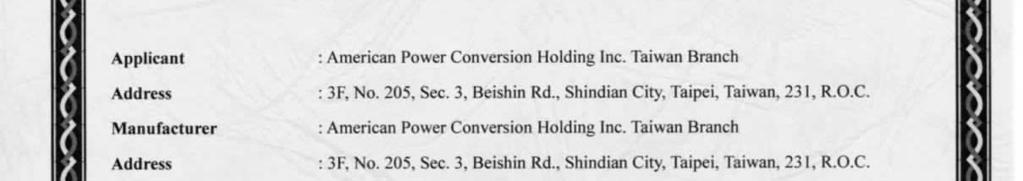
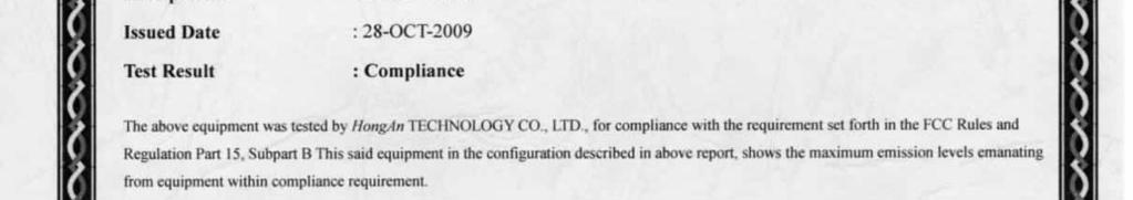
4 1. General Information Applicant : American Power Conversion Holding Inc. Taiwan Branch Address : 3F, No. 205, Sec. 3, Beishin Rd., Shindian City, Taipei, Taiwan, 231, R.O.C. Manufacturer : American Power Conversion Holding Inc. Taiwan Branch Address : 3F, No. 205, Sec. 3, Beishin Rd., Shindian City, Taipei, Taiwan, 231, R.O.C. Description of EUT : Uninterruptible Power System Trade Name : APC Model Number : BX1500G; BX1300G; BN1250G; BR1500G;BR1300G BX1500XXXXXXXXXX;BX1300XXXXXXXXXX; BN1250XXXXXXXXXX;BR1500 XXXXXXXXXX; BR1300XXXXXXXXXX. ( X can be 0-9, A-Z, - or blank ) Report Number : HA SAFD Receipt Date : 24-MAR-2009 Issued Date : 28-OCT-2009
5 1.1 Product Information EUT Information Trade Name Description of EUT Model Number Serial Number AC Power during test AC Power Cord Type : APC : Uninterruptible Power System : BX1500G : N/A : AC 120V/60Hz. : 3 Pins, Unshielded, 2m (Undetachable). I/O Port of EUT I/O Port Type Q TY Tested With Cable 1. AC Inlet 1 1 Unshielded, 2.0m 2. Coaxial Port 2 2 Shielded, 1.0m 3. Network Port 2 2 Unshielded, 1.8m 4. Data Port 1 1 Unshielded, 2.0m With core*1 5. AC Outlet (Back + Surge) 8 8 Unshielded, 1.8m 6. AC Outlet (Surge only) 2 2 Unshielded, 1.8m
6 Description of EUT: Model Number BX1500G BR1500G BX1300G BR1300G BN1250G Tested Yes Yes Yes Yes No Inputs Outlet Nominal Voltage Rated Voltage Frequency Rated Current I/p voltage window for utlity operation Input Over Current Protection O/P voltage on mains mode 120 Vac 120Vac 45 ~ 65 Hz 12A Vac Vac Vac Vac Vac 98.5 to 139 Vac 98.5 to 126 Vac 15A Circuit Breaker 98.5 to 139 Vac O/P voltage on Battery mode 115 Vac +/- 8% Battery Outlet Ratings: 98.5 to 126 Vac 98.5 to 139 Vac Rated VA 1500 VA 1300 VA 1250 VA Rated Watts 865 Watts 780 Watts 750 Watts Rated Current 12.5A 10.8A 10.4A Rated Xcap Load Capacitance 12.5uF 10.5 uf 10.4uF Monitor Size Supported (typical) 2 x 21" Frequency (on battery): Following transfer from ac line 50 or 60 Hz +/- 1Hz auto sensing Note:1.Manufacture define the output power cord is less than 10m, and the cable for the data port is less than 3m. 2.For more detail features, please refer to User s Manual. Additional Model Number: The model number as listed had been investigated which compliance with the requirement standard, there are the same appearance, function and schematic but the model number is difference. Model Number: BX1500G; BX1300G; BN1250G; BR1500G;BR1300G; BX1500XXXXXXXXXX;BX1300XXXXXXXXXX; BN1250XXXXXXXXXX;BR1500XXXXXXXXXXX;BR1300XXXXXXXXXX ( X can be 0-9, A-Z, - or blank )
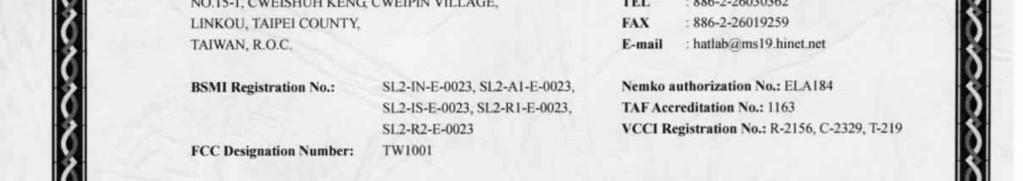
7 1.2 Test Methodology a. The emission tests was performed according to the following methods and procedures: FCC PART 15 (47 CFR Ch.1; Edition) Radio Frequency Devices b. Description of departing from standard test method & any other specific: NONE 1.3 Test Facility The HongAn TECHNOLOGY CO., LTD. test site located at: No 15-1, Cweishuh Keng, Cweipin Village,Linkou, Taipei County, Taiwan, R. O. C. It is an open field test site, capable of measuring ITE products with the product on turntable (dimension of 1.2 meters) to antenna at distance of 3 and 10 meters. Anechoic chamber 9m (H) X 6m (W) X 6m (L) is compliance with the sixteen point uniform field requirement as stated in EN /IEC It is an EMS test site, Capable of measuring Industrial, Scientific and Medical Instrument, Information Technology Equipment, broadcast receivers and related equipments and household appliances/tools. It is owned and operated by HongAn TECHNOLOGY CO., LTD. A site description and calibration report to ANSI C 63.4 is available upon request. A site description and calibration report to EN & EN55024 is available upon request. The test site is authorized for testing Industrial, Scientific and Medical Instrument, Information Technology Equipment, broadcast receivers and related equipments and household Appliances / tools b BSMI.Nemko authorizes the test site for testing Uninterruptible Power System and Automatic Voltage Regulator. BSMI certification #: SL2-IS-E-0023, SL2-IN-E-0023, SL2-R1-E-0023, SL2-R2-E-0023, And SL2-A1-E Nemko authorization #: ELA 184 VCCI Certificate #: R-2156,C-2329,T-219 TAF Accreditation Number: 1163 FCC Designation Number: TW1001
8 1.4 System Test Configuration Tested of Setup System Configuration of Test System 100ohm DUP*8 UUP UTP 100ohm UTP DSD 75ohm 75ohm DSD DUP DSD DSD DUP Lamp EUT PC Monitor DUP*2 DUP DSD Modem Lamp USD USD Keyboard Mouse Legend: UTP: Unshielded Data Twisted Pair Cable. DUP: Detachable Unshielded Power Cord. UUP: Undetachable Unshielded Power Cord. USP: Undetachable Shielded Power Cord. USD: Undetachable Shielded Data Cable. DSD: Detachable Shielded Data Cable UUD: Undetachable Unshielded Data Cable DUD: Detachable Unshielded Data Cable
9 Support Equipment List Equipment Model Number Serial Number EMC Approved Manufacturer Data Cable Description Power Cable Monitor ( LCD ) SDM-X FCC Doc SONY Shielded(Braid) 1.8m, with core*2 Unshielded, 2.0m with core*2 PC DCTA 5MCGJ1S FCC Doc, CE Mark DELL ( RJ45 USB) Shielded(Braid) 2.0m with core*1 Unshielded, 1.8m Modem E FCC Doc, CE Mark MITAC Shielded(Braid) 1.0m Unshielded 1.0m with core*1 Keyboard ( USB ) Y-UR FCC Doc, CE Mark Logitech Shielded(Foil), 1.8m N/A Mouse ( USB ) M-BT FCC Doc Logitech Shielded(Foil), 1.8m N/A LAMP LIGHT N/A N/A HongAn N/A ( EUT AC Outlet ) Unshielded, 1.8m*8 LAMP LIGHT N/A N/A HongAn N/A ( EUT AC Outlet ) Unshielded, 1.8m*2 R 75 ohm N/A N/A HongAn R 100 ohm N/A N/A APC ( Coaxial ) Shielded (Braid), 1.0m*2 ( UTP ) Unshielded, 1.8m*2 N/A N/A
10 1.4.2 EUT Exercise Software 1.Turn on the power of all support equipment. 2.Turn on the power of EUT. 3.PC read messages by EUT connect cable when Execution software of EUT Justification The worse case of the conducted disturbance at the mains port measurement occurred at 3.815MHz (Phase),-4.030dB(Average) at Battery mode. The worst case of the radiated measurements is dB(Vertical) occurred at MHz (Quasi Peak),100cm antenna height and 173degree turn table angle at Battery mode. The EUT Model Number BX1300 test data shown as attachment (Page5-2~5-7). The Model Number BR1500G and BR1300G test data shown as attachment (Page5-8~5-19).
11 2. EMI Test 2.1. Conducted Emission All conducted emission testing was performed in accordance with ANSI C63.4 and CISPR Publication 22 inside a shielded room Conducted Emission Limit CISPR 22 /FCC Port 15 Limits for conducted disturbance at the main ports of class B ITE. Frequency Range Limit [db (µv)] MHz Quasi-Peak Average 0.15~ ~56 56~ ~ ~ Notes 1-The lower limit shall apply at the transition frequencies. Notes 2-The limit decreases linearly with the logarithm of the frequency in the range0.15mhz to 0.50MHz Conducted Test Equipment Instrument Name Manufacture Model Serial Number Last Cal. Date Next Cal. Date EMI Test Signal Analyzer PMM PMM J JUL JUL-2010 LISN EMCO 3810/2NM JUL JUL-2010 LISN Rolf Heine Hochfrequenztechnik NNB-4/32T FEB FEB-2010 The test equipment used is calibrated and can be traced to National ITRI and International Standards The result of the measurement, after all appropriate corrections have been made, is y and may typically be reported as follows: The measured result is : y db V ±3.95dB for a level of confidence of approximately 95%, (K=2).
 Limit(QP) Margin (MHz) db db Note 0.150 23.600 0.140 23.740 56.000 66.000-32.260 P AV 0.150 47.100 0.140 47.240 56.000 66.000-18.760 P QP 0.919 21.100 0.210 21.310 46.000 56.")
12 2.1.3 Conducted Emission Test Conducted Test Data Location : HA2 Power Mains : 120V/60Hz Model Name : BX1500G Humidity : 53% Description : Phase (Line Mode) Temperature : 20 Frequency Measured Corr. Factor Total Limit(AV) Limit(QP) Margin (MHz) db db Note P AV P QP P AV P QP P QP P AV P QP P AV P AV P QP P QP P AV Peak, Average and QP signifies the measurement detector used for performing measurements. Negative number in the margin column indicates the amount (in db) that the recorded emission is below the limit. P denotes Phase, N denotes Neutral, AV denotes Average, QP denotes Quasi-Peak. For the same frequency only the highest reading of Phase or Neutral conductor is reported. Correction Factor =Insertion loss+ Cable loss. Margin value = (Measured+ Correction Factor) limit value. All tested equipment is within calibration and are operated in accordance with the instructions of the manufacturers. Test Number: 2CE33006 Test Date: 30- MAR-2009 Tested By: H.B.LIANG
 Limit(QP) Margin (MHz) db db Note 0.150 26.200 0.140 26.340 56.000 66.000-29.660 N AV 0.150 48.300 0.140 48.440 56.000 66.000-17.560 N QP 0.263 33.100 0.150 33.250 51.330 61.")
13 Conducted Test Data Location : HA2 Power Mains : 120V/60Hz Model Name : BX1500G Humidity : 53% Description : Neutral (Line Mode) Temperature : 20 Frequency Measured Corr. Factor Total Limit(AV) Limit(QP) Margin (MHz) db db Note N AV N QP N QP N AV N QP N AV N AV N QP N QP N AV N AV N QP Peak, Average and QP signifies the measurement detector used for performing measurements. Negative number in the margin column indicates the amount (in db) that the recorded emission is below the limit. P denotes Phase, N denotes Neutral, AV denotes Average, QP denotes Quasi-Peak. For the same frequency only the highest reading of Phase or Neutral conductor is reported. Correction Factor =Insertion loss+ Cable loss. Margin value = (Measured+ Correction Factor) limit value. All tested equipment is within calibration and are operated in accordance with the instructions of the manufacturers. Test Number: 2CE33006 Test Date: 30-MAR-2009 Tested By: H.B.LIANG
 Limit(QP) Margin (MHz) db DB Note 0.157 27.100 0.140 27.240 55.620 65.620-28.380 P AV 0.157 54.400 0.140 54.540 55.620 65.620-11.080 P QP 0.693 33.800 0.190 33.990 46.000 56.")
14 Conducted Test Data Location : HA2 Power Mains : OV Model Name : BX1500G Humidity : 53% Description : Phase (Battery Mode ) Temperature : 20 Frequency Measured Corr. Factor Total Limit(AV) Limit(QP) Margin (MHz) db DB Note P AV P QP P AV P QP P AV P QP P QP P AV P AV P QP P QP P AV Peak, Average and QP signifies the measurement detector used for performing measurements. Negative number in the margin column indicates the amount (in db) that the recorded emission is below the limit. P denotes Phase, N denotes Neutral, AV denotes Average, QP denotes Quasi-Peak. For the same frequency only the highest reading of Phase or Neutral conductor is reported. Correction Factor =Insertion loss+ Cable loss. Margin value = (Measured+ Correction Factor) limit value. All tested equipment is within calibration and are operated in accordance with the instructions of the manufacturers. Test Number: 2CE33005 Test Date: 30-MAR-2009 Tested By: H.B.LIANG
 Limit(QP) Margin (MHz) db db Note 0.150 26.100 0.110 26.210 56.000 66.000-29.790 N AV 0.150 52.300 0.110 52.410 56.000 66.000-13.590 N QP 0.157 57.000 0.110 57.110 55.620 65.")
15 Conducted Test Data Location : HA2 Power Mains : OV Model Name : BX1500G Humidity : 53% Description : Neutral (Battery Mode ) Temperature : 20 Frequency Measured Corr. Factor Total Limit(AV) Limit(QP) Margin (MHz) db db Note N AV N QP N QP N AV N QP N AV N AV N QP N AV N QP N QP N AV Peak, Average and QP signifies the measurement detector used for performing measurements. Negative number in the margin column indicates the amount (in db) that the recorded emission is below the limit. P denotes Phase, N denotes Neutral, AV denotes Average, QP denotes Quasi-Peak. For the same frequency only the highest reading of Phase or Neutral conductor is reported. Correction Factor =Insertion loss+ Cable loss. Margin value = (Measured+ Correction Factor) limit value. All tested equipment is within calibration and are operated in accordance with the instructions of the manufacturers. Test Number: 2CE33005 Test Date: 30-MAR-2009 Tested By: H.B.LIANG
16 2.2 Radiated Emission All radiated testing was performed on the site referenced in accordance with ANSIC 63.4 and CISPR Radiated Emission Limit CISPR 22 Frequency range (MHz) Test distance (meter) Quasi-Peak limits [db (µv)] 30~ ~ Notes1-The lower limit shall apply at the transition frequencies. Notes2-Additional provisions may be required for cases where interference occurs. FCC Part 15 Frequency range (MHz) Test distance (meter) Limits [db (µv)] 30~ ~ ~ Above 3 54 Notes1- On any frequency or frequencies below or equal to 1000 MHz, the limits shown are based on measuring equipment employing a CISPR quasi-peak detector function and related measurement band widths, unless otherwise specified. Notes2- On any frequency or frequencies above 1000 MHz, unless otherwise stated, the radiated limits shown based on the use of measurement instrumentation employing an average detector function Radiated Test Equipment Instrument Manufacture Name EMI Test Signal Analyzer Spectrum Analyzer Model Number Serial Number Last Cal. Date Next Cal. Date PMM PMM J JUL JUL-2010 ADVANTEST R JUN JUN-2010 Preamplifier CHASE CPA 9231A JUL JUL-2010 Bilog Antenna CHASE CBL 6112B AUG AUG-2010 The test equipment used is calibrated and can be traced to National ITRI and International Standards. The result of the measurement, after all appropriate corrections have been made, is y and may typically be reported as follows: The measured result is : y db V ± 5.04dB for a level of confidence of approximately 95%, (K=2).
17 2.2.3 Radiated Emission Test Radiated Test Data The following data lists the significant emission frequencies measured levels, correction factor (includes cable and antenna corrections) plus the limit. Explanation of the correction factor is given in paragraph Frequency (MHz) Location : HA2 Model Name : BX1500G Humidity : 40% Description : Line Mode Temperature : 22 Receiver Reading Corr. Factor db Corr. Reading Limit Margin limit Pol. Antenna Height ( cm ) Table Ang. ( deg. ) H QP V QP H V H V V H V H V H Negative number in the margin column indicates the amount (in db) that the recorded emission is Below the limit. V means in Vertical Antenna Polarization, H means in Horizontal, QP means in Quasi-Peak, and AV means in average. Unless stated otherwise, all readings are measured peak with an IF bandwidth not less than 120KHz. Above 1 GHz test used a receiver bandwidth of 1 MHz. If a spectrum analyzer is used, the sweep time and video filter settings will not affect the readings. Radiated emissions for this type of product do not change with the AC power operating voltage. This mast was positioned such that the distance from the antenna to the system under test was 10 meter, except required testing above 1 GHz which is performed at a distance of 3 meter. The measurement in the margin limit column indicates the amount in (db) that the recorded emission 0~6 db is acceptable for open case. Note Test Number: 2RE40207 Test Date: 02-APR-2009 Tested By: H.B.LIANG
18 Frequency (MHz) Radiated Test Data Location : HA2 Model Name : BX1500G Humidity : 40% Description : Battery Mode Temperature : 22 Receiver Reading Corr. Factor db Corr. Reading Limit Margin limit Pol. Antenna Height ( cm ) Table Ang. ( deg. ) H QP V QP H V V H V H H H QP V QP V Negative number in the margin column indicates the amount (in db) that the recorded emission is Below the limit. V means in Vertical Antenna Polarization, H means in Horizontal, QP means in Quasi-Peak, and AV means in average. Unless stated otherwise, all readings are measured peak with an IF bandwidth not less than 120KHz. Above 1 GHz test used a receiver bandwidth of 1 MHz. If a spectrum analyzer is used, the sweep time and video filter settings will not affect the readings. Radiated emissions for this type of product do not change with the AC power operating voltage. This mast was positioned such that the distance from the antenna to the system under test was 10 meter, except required testing above 1 GHz which is performed at a distance of 3 meter. The measurement in the margin limit column indicates the amount in (db) that the recorded emission 0~6 db is acceptable for open case Note Test Number: 2RE40206 Test Date: 02-APR-2009 Tested By: H.B.LIANG
19 2.2.4 Field Strength Calculation The field strength is calculated by adding the Correction factor to the receiver or analyzer reading to determine the resultant field strength. The correction factor is determined by adding the antenna factor and the loss of the cables connection the antenna to the receiver. Front-end amplifier gain if any is accounted for in the receiver reading. The basic equation with a sample calculation is as follows: FS = RA + CF Where the Correction factor CF is the sum of the Antenna Factor AF and the Cable loss factor CL; CF = AF + CL FS = Field Strength AF = Antenna Factor CL = Cable Loss factor RA = Receiver Amplitude Assume a receiver reading of 22dB( V/m) is obtained. The Antenna factor of 7.4 db and a cable loss factor of 1.1 db are added to yield 8.5 db Correction Factor. The Calculated Field Strength is the sum of = 30.5 db ( V/m). All values are listed as db, either referenced to 1 V or 1 V/m.
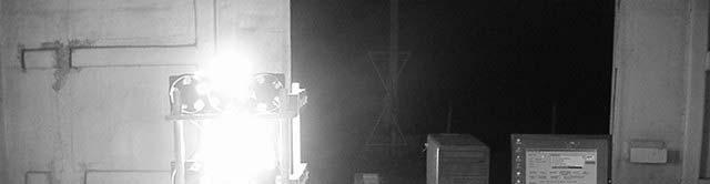

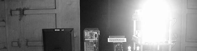

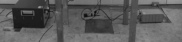
20 3. Photographs of Test Setup 3.1 Test Setup of Radiated Emission Test


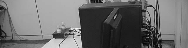
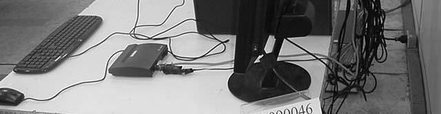

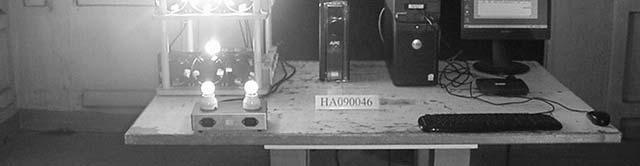
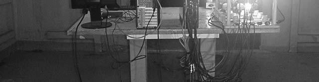
21 3.2 Test Setup of Conducted Emission Test


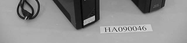
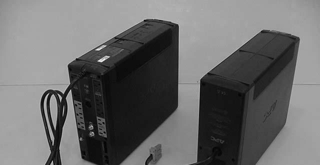
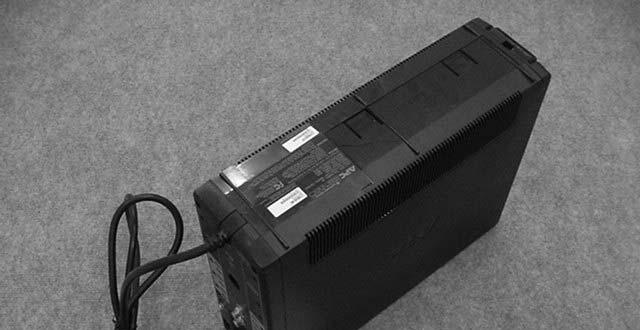
22 4. Photographs of EUT 4.1 EUT Front Side (BX1500G) 4.2 EUT Rear Side (BX1500G)

")


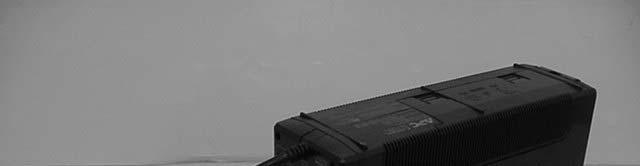
23 4.3 EUT Front Side (BX1300G) 4.4 EUT Rear Side (BX1300G)

")
24 4.3 EUT Front Side (BR1500G) 4.3 EUT Rear Side (BR1500G)

")


25 4.3 EUT Front Side (BR1300G) 4.3 EUT Rear Side (BR1300G)
26 5. Attached Test Data Model Name: BX1300G Page Conducted Test Data 5-2 Radiated Test Data 5-6 Model Name: BR1500G&BR1300G Conducted Test Data 5-8 Radiated Test Data
 Limit(QP) Margin (MHz) db db Note 0.150 50.100 0.140 50.240 56.000 66.000-15.760 P QP 0.150 34.400 0.140 34.540 56.000 66.000-21.460 P AV 0.525 26.200 0.180 26.380 46.000 56.")
27 Conducted Test Data Location : HA2 Power Mains : 120V/60Hz Model Name : BX1300G Humidity : 54% Description : Phase (Line Mode) Temperature : 20 Frequency Measured Corr. Factor Total Limit(AV) Limit(QP) Margin (MHz) db db Note P QP P AV P AV P QP P QP P AV P AV P QP P QP P AV P AV P QP Peak, Average and QP signifies the measurement detector used for performing measurements. Negative number in the margin column indicates the amount (in db) that the recorded emission is below the limit. P denotes Phase, N denotes Neutral, AV denotes Average, QP denotes Quasi-Peak. For the same frequency only the highest reading of Phase or Neutral conductor is reported. Correction Factor =Insertion loss+ Cable loss. Margin value = (Measured+ Correction Factor) limit value. All tested equipment is within calibration and are operated in accordance with the instructions of the manufacturers. Test Number: 2CE33004 Test Date: 30- MAR-2009 Tested By: H.B.LIANG
 Limit(QP) Margin (MHz) db db Note 0.150 51.100 0.110 51.210 56.000 66.000-14.790 N QP 0.150 34.500 0.110 34.610 56.000 66.000-21.390 N AV 0.165 26.700 0.110 26.810 55.200 65.")
28 Conducted Test Data Location : HA2 Power Mains : 120V/60Hz Model Name : BX1300G Humidity : 54% Description : Neutral (Line Mode) Temperature : 20 Frequency Measured Corr. Factor Total Limit(AV) Limit(QP) Margin (MHz) db db Note N QP N AV N AV N QP N AV N QP N QP N AV N QP N AV N AV N QP Peak, Average and QP signifies the measurement detector used for performing measurements. Negative number in the margin column indicates the amount (in db) that the recorded emission is below the limit. P denotes Phase, N denotes Neutral, AV denotes Average, QP denotes Quasi-Peak. For the same frequency only the highest reading of Phase or Neutral conductor is reported. Correction Factor =Insertion loss+ Cable loss. Margin value = (Measured+ Correction Factor) limit value. All tested equipment is within calibration and are operated in accordance with the instructions of the manufacturers. Test Number: 2CE33004 Test Date: 30-MAR-2009 Tested By: H.B.LIANG
 Limit(QP) Margin (MHz) db DB Note 0.150 55.700 0.110 55.810 56.000 66.000-10.190 P QP 0.150 29.500 0.110 29.610 56.000 66.000-26.390 P AV 0.159 26.500 0.110 26.610 55.510 65.")

29 Conducted Test Data Location : HA2 Power Mains : OV Model Name : BX1300G Humidity : 54% Description : Phase (Battery Mode ) Temperature : 20 Frequency Measured Corr. Factor Total Limit(AV) Limit(QP) Margin (MHz) db DB Note P QP P AV P AV P QP P AV P QP P AV P QP P QP P AV P QP P AV Peak, Average and QP signifies the measurement detector used for performing measurements. Negative number in the margin column indicates the amount (in db) that the recorded emission is below the limit. P denotes Phase, N denotes Neutral, AV denotes Average, QP denotes Quasi-Peak. For the same frequency only the highest reading of Phase or Neutral conductor is reported. Correction Factor =Insertion loss+ Cable loss. Margin value = (Measured+ Correction Factor) limit value. All tested equipment is within calibration and are operated in accordance with the instructions of the manufacturers. Test Number: 2CE33003 Test Date: 30-MAR-2009 Tested By: H.B.LIANG
 Limit(QP) Margin (MHz) db db Note 0.150 30.000 0.110 30.110 56.000 66.000-25.890 N AV 0.150 56.800 0.110 56.910 56.000 66.000-9.090 N QP 0.161 58.400 0.110 58.510 55.410 65.")
30 Conducted Test Data Location : HA2 Power Mains : OV Model Name : BX1300G Humidity : 54% Description : Neutral (Battery Mode ) Temperature : 20 Frequency Measured Corr. Factor Total Limit(AV) Limit(QP) Margin (MHz) db db Note N AV N QP N QP N AV N AV N QP N AV N QP N QP N AV N AV N QP Peak, Average and QP signifies the measurement detector used for performing measurements. Negative number in the margin column indicates the amount (in db) that the recorded emission is below the limit. P denotes Phase, N denotes Neutral, AV denotes Average, QP denotes Quasi-Peak. For the same frequency only the highest reading of Phase or Neutral conductor is reported. Correction Factor =Insertion loss+ Cable loss. Margin value = (Measured+ Correction Factor) limit value. All tested equipment is within calibration and are operated in accordance with the instructions of the manufacturers. Test Number: 2CE33003 Test Date: 30-MAR-2009 Tested By: H.B.LIANG
31 Frequency (MHz) Radiated Test Data Location : HA2 Model Name : BX1300G Humidity : 40% Description : Line Mode Temperature : 21 Receiver Reading Corr. Factor db Corr. Reading Limit Margin limit Pol. Antenna Height ( cm ) Table Ang. ( deg. ) V QP H V V V H H H V QP H QP H V Negative number in the margin column indicates the amount (in db) that the recorded emission is Below the limit. V means in Vertical Antenna Polarization, H means in Horizontal, QP means in Quasi-Peak, and AV means in average. Unless stated otherwise, all readings are measured peak with an IF bandwidth not less than 120KHz. Above 1 GHz test used a receiver bandwidth of 1 MHz. If a spectrum analyzer is used, the sweep time and video filter settings will not affect the readings. Radiated emissions for this type of product do not change with the AC power operating voltage. This mast was positioned such that the distance from the antenna to the system under test was 10 meter, except required testing above 1 GHz which is performed at a distance of 3 meter. The measurement in the margin limit column indicates the amount in (db) that the recorded emission 0~6 db is acceptable for open case. Note Test Number: 2RE40202 Test Date: 02-APR-2009 Tested By: H.B.LIANG
32 Frequency (MHz) Radiated Test Data Location : HA2 Model Name : BX1300G Humidity : 40% Description : Battery Mode Temperature : 20 Receiver Reading Corr. Factor db Corr. Reading Limit Margin limit Pol. Antenna Height ( cm ) Table Ang. ( deg. ) H V QP V H V H H V H H QP V QP V Negative number in the margin column indicates the amount (in db) that the recorded emission is Below the limit. V means in Vertical Antenna Polarization, H means in Horizontal, QP means in Quasi-Peak, and AV means in average. Unless stated otherwise, all readings are measured peak with an IF bandwidth not less than 120KHz. Above 1 GHz test used a receiver bandwidth of 1 MHz. If a spectrum analyzer is used, the sweep time and video filter settings will not affect the readings. Radiated emissions for this type of product do not change with the AC power operating voltage. This mast was positioned such that the distance from the antenna to the system under test was 10 meter, except required testing above 1 GHz which is performed at a distance of 3 meter. The measurement in the margin limit column indicates the amount in (db) that the recorded emission 0~6 db is acceptable for open case Note Test Number: 2RE40201 Test Date: 02-APR-2009 Tested By: H.B.LIANG
 Limit(QP) Margin (MHz) db db Note 0.150 48.900 0.240 49.140 56.000 66.000-6.860 P AV 0.150 54.600 0.240 54.840 56.000 66.000-11.160 P QP 0.524 37.000 0.190 37.190 46.000 56.")

33 Conducted Test Data Location : HA2 Power Mains : 120V/60Hz Model Name : BR1500G Humidity : 60% Description : Phase Temperature : 23 Frequency Measured Corr. Factor Total Limit(AV) Limit(QP) Margin (MHz) db db Note P AV P QP P QP P AV P QP P AV P AV P QP P AV P QP P QP P AV Peak, Average and QP signifies the measurement detector used for performing measurements. Negative number in the margin column indicates the amount (in db) that the recorded emission is below the limit. P denotes Phase, N denotes Neutral, AV denotes Average, QP denotes Quasi-Peak. For the same frequency only the highest reading of Phase or Neutral conductor is reported. Correction Factor =Insertion loss+ Cable loss. Margin value = (Measured+ Correction Factor) limit value. All tested equipment is within calibration and are operated in accordance with the instructions of the manufacturers. Test Number: 2CEA1906 Test Date: 19- OCT-2009 Tested By: H.B.LIANG
 Limit(QP) Margin (MHz) db db Note 0.174 44.200 0.170 44.370 54.760 64.760-20.390 N QP 0.174 36.300 0.170 36.470 54.760 64.760-18.290 N AV 0.524 30.900 0.160 31.060 46.000 56.")

34 Conducted Test Data Location : HA2 Power Mains : 120V/60Hz Model Name : BR1500G Humidity : 60% Description : Neutral Temperature : 23 Frequency Measured Corr. Factor Total Limit(AV) Limit(QP) Margin (MHz) db db Note N QP N AV N AV N QP N QP N AV N AV N QP N QP N AV N AV N QP Peak, Average and QP signifies the measurement detector used for performing measurements. Negative number in the margin column indicates the amount (in db) that the recorded emission is below the limit. P denotes Phase, N denotes Neutral, AV denotes Average, QP denotes Quasi-Peak. For the same frequency only the highest reading of Phase or Neutral conductor is reported. Correction Factor =Insertion loss+ Cable loss. Margin value = (Measured+ Correction Factor) limit value. All tested equipment is within calibration and are operated in accordance with the instructions of the manufacturers. Test Number: 2CEA1906 Test Date: 19-OCT-2009 Tested By: H.B.LIANG
 Limit(QP) Margin (MHz) db DB Note 0.552 25.400 0.190 25.590 46.000 56.000-20.410 P AV 0.552 30.300 0.190 30.490 46.000 56.000-25.510 P QP 1.325 30.900 0.240 31.140 46.000 56.000-24.")

35 Conducted Test Data Location : HA2 Power Mains : Battery Mode Model Name : BR1500G Humidity : 60% Description : Phase Temperature : 23 Frequency Measured Corr. Factor Total Limit(AV) Limit(QP) Margin (MHz) db DB Note P AV P QP P QP P AV P AV P QP P AV P QP P QP P AV P AV P QP Peak, Average and QP signifies the measurement detector used for performing measurements. Negative number in the margin column indicates the amount (in db) that the recorded emission is below the limit. P denotes Phase, N denotes Neutral, AV denotes Average, QP denotes Quasi-Peak. For the same frequency only the highest reading of Phase or Neutral conductor is reported. Correction Factor =Insertion loss+ Cable loss. Margin value = (Measured+ Correction Factor) limit value. All tested equipment is within calibration and are operated in accordance with the instructions of the manufacturers. Test Number: 2CEA1905 Test Date: 19-OCT-2009 Tested By: H.B.LIANG
 Limit(QP) Margin (MHz) db db Note 0.551 24.400 0.160 24.560 46.000 56.000-31.440 N QP 0.551 19.300 0.160 19.460 46.000 56.000-26.540 N AV 0.993 24.000 0.180 24.180 46.000 56.000-21.")

36 Conducted Test Data Location : HA2 Power Mains : Battery Mode Model Name : BR1500G Humidity : 60% Description : Neutral Temperature : 23 Frequency Measured Corr. Factor Total Limit(AV) Limit(QP) Margin (MHz) db db Note N QP N AV N AV N QP N QP N AV N AV N QP N QP N AV N AV N QP Peak, Average and QP signifies the measurement detector used for performing measurements. Negative number in the margin column indicates the amount (in db) that the recorded emission is below the limit. P denotes Phase, N denotes Neutral, AV denotes Average, QP denotes Quasi-Peak. For the same frequency only the highest reading of Phase or Neutral conductor is reported. Correction Factor =Insertion loss+ Cable loss. Margin value = (Measured+ Correction Factor) limit value. All tested equipment is within calibration and are operated in accordance with the instructions of the manufacturers. Test Number: 2CEA1905 Test Date: 19-OCT-2009 Tested By: H.B.LIANG
 Limit(QP) Margin (MHz) db db Note 0.150 44.600 0.240 44.840 56.000 66.000-11.160 P AV 0.150 50.300 0.240 50.540 56.000 66.000-15.460 P QP 0.526 33.200 0.190 33.390 46.000 56.")

37 Conducted Test Data Location : HA2 Power Mains : 120V/60Hz Model Name : BR1300G Humidity : 48% Description : Phase Temperature : 23 Frequency Measured Corr. Factor Total Limit(AV) Limit(QP) Margin (MHz) db db Note P AV P QP P QP P AV P AV P QP P QP P AV P AV P QP P QP P AV Peak, Average and QP signifies the measurement detector used for performing measurements. Negative number in the margin column indicates the amount (in db) that the recorded emission is below the limit. P denotes Phase, N denotes Neutral, AV denotes Average, QP denotes Quasi-Peak. For the same frequency only the highest reading of Phase or Neutral conductor is reported. Correction Factor =Insertion loss+ Cable loss. Margin value = (Measured+ Correction Factor) limit value. All tested equipment is within calibration and are operated in accordance with the instructions of the manufacturers. Test Number: 2CEA1902 Test Date: 19- OCT Tested By: H.B.LIANG
 Limit(QP) Margin (MHz) db db Note 0.150 41.300 0.210 41.510 56.000 66.000-14.490 N AV 0.150 47.600 0.210 47.810 56.000 66.000-18.190 N QP 0.525 34.300 0.160 34.460 46.000 56.")

38 Conducted Test Data Location : HA2 Power Mains : 120V/60Hz Model Name : BR1300G Humidity : 48% Description : Neutral Temperature : 23 Frequency Measured Corr. Factor Total Limit(AV) Limit(QP) Margin (MHz) db db Note N AV N QP N QP N AV N AV N QP N AV N QP N QP N AV N QP N AV Peak, Average and QP signifies the measurement detector used for performing measurements. Negative number in the margin column indicates the amount (in db) that the recorded emission is below the limit. P denotes Phase, N denotes Neutral, AV denotes Average, QP denotes Quasi-Peak. For the same frequency only the highest reading of Phase or Neutral conductor is reported. Correction Factor =Insertion loss+ Cable loss. Margin value = (Measured+ Correction Factor) limit value. All tested equipment is within calibration and are operated in accordance with the instructions of the manufacturers. Test Number: 2CEA1902 Test Date: 19-OCT-2009 Tested By: H.B.LIANG
 Limit(QP) Margin (MHz) db DB Note 0.219 36.600 0.170 36.770 52.850 62.850-26.080 P QP 0.219 31.100 0.170 31.270 52.850 62.850-21.580 P AV 0.550 24.900 0.190 25.090 46.000 56.")

39 Conducted Test Data Location : HA2 Power Mains : Battery Mode Model Name : BR1300G Humidity : 48% Description : Phase Temperature : 23 Frequency Measured Corr. Factor Total Limit(AV) Limit(QP) Margin (MHz) db DB Note P QP P AV P AV P QP P AV P QP P QP P AV P AV P QP P QP P AV Peak, Average and QP signifies the measurement detector used for performing measurements. Negative number in the margin column indicates the amount (in db) that the recorded emission is below the limit. P denotes Phase, N denotes Neutral, AV denotes Average, QP denotes Quasi-Peak. For the same frequency only the highest reading of Phase or Neutral conductor is reported. Correction Factor =Insertion loss+ Cable loss. Margin value = (Measured+ Correction Factor) limit value. All tested equipment is within calibration and are operated in accordance with the instructions of the manufacturers. Test Number: 2CEA1901 Test Date: 19-OCT-2009 Tested By: H.B.LIANG
 Limit(QP) Margin (MHz) db db Note 0.217 39.800 0.140 39.940 52.930 62.930-22.990 N QP 0.217 34.400 0.140 34.540 52.930 62.930-18.390 N AV 0.508 8.200 0.160 8.360 46.000 56.")

40 Conducted Test Data Location : HA2 Power Mains : Battery Mode Model Name : BR1300G Humidity : 48% Description : Neutral Temperature : 23 Frequency Measured Corr. Factor Total Limit(AV) Limit(QP) Margin (MHz) db db Note N QP N AV N AV N QP N QP N AV N AV N QP N QP N AV N AV N QP Peak, Average and QP signifies the measurement detector used for performing measurements. Negative number in the margin column indicates the amount (in db) that the recorded emission is below the limit. P denotes Phase, N denotes Neutral, AV denotes Average, QP denotes Quasi-Peak. For the same frequency only the highest reading of Phase or Neutral conductor is reported. Correction Factor =Insertion loss+ Cable loss. Margin value = (Measured+ Correction Factor) limit value. All tested equipment is within calibration and are operated in accordance with the instructions of the manufacturers. Test Number: 2CEA1901 Test Date: 19-OCT-2009 Tested By: H.B.LIANG
41 Frequency (MHz) Radiated Test Data Location : HA2 Model Name : BR1500G Humidity : 60% Description : 120V/60Hz Temperature : 25 Receiver Reading Corr. Factor db Corr. Reading Limit Margin limit Pol. Antenna Height ( cm ) Table Ang. ( deg. ) H QP V QP H V QP V H V H H V V H Negative number in the margin column indicates the amount (in db) that the recorded emission is Below the limit. V means in Vertical Antenna Polarization, H means in Horizontal, QP means in Quasi-Peak, and AV means in average. Unless stated otherwise, all readings are measured peak with an IF bandwidth not less than 120KHz. Above 1 GHz test used a receiver bandwidth of 1 MHz. If a spectrum analyzer is used, the sweep time and video filter settings will not affect the readings. Radiated emissions for this type of product do not change with the AC power operating voltage. This mast was positioned such that the distance from the antenna to the system under test was 10 meter, except required testing above 1 GHz which is performed at a distance of 3 meter. The measurement in the margin limit column indicates the amount in (db) that the recorded emission 0~6 db is acceptable for open case. Note Test Number: 2REA2206 Test Date: 22-OCT-2009 Tested By: H.B.LIANG
42 Frequency (MHz) Radiated Test Data Location : HA2 Model Name : BR1500G Humidity : 60% Description : Battery Mode Temperature : 25 Receiver Reading Corr. Factor db Corr. Reading Limit Margin limit Pol. Antenna Height ( cm ) Table Ang. ( deg. ) H QP V QP V QP H V H V QP H V H H V Negative number in the margin column indicates the amount (in db) that the recorded emission is Below the limit. V means in Vertical Antenna Polarization, H means in Horizontal, QP means in Quasi-Peak, and AV means in average. Unless stated otherwise, all readings are measured peak with an IF bandwidth not less than 120KHz. Above 1 GHz test used a receiver bandwidth of 1 MHz. If a spectrum analyzer is used, the sweep time and video filter settings will not affect the readings. Radiated emissions for this type of product do not change with the AC power operating voltage. This mast was positioned such that the distance from the antenna to the system under test was 10 meter, except required testing above 1 GHz which is performed at a distance of 3 meter. The measurement in the margin limit column indicates the amount in (db) that the recorded emission 0~6 db is acceptable for open case Note Test Number: 2REA2205 Test Date: 22-OCT-2009 Tested By: H.B.LIANG
43 Frequency (MHz) Radiated Test Data Location : HA2 Model Name : BR1300G Humidity : 60% Description : 120V/60Hz Temperature : 25 Receiver Reading Corr. Factor db Corr. Reading Limit Margin limit Pol. Antenna Height ( cm ) Table Ang. ( deg. ) H QP V QP V V H H V H V H V H Negative number in the margin column indicates the amount (in db) that the recorded emission is Below the limit. V means in Vertical Antenna Polarization, H means in Horizontal, QP means in Quasi-Peak, and AV means in average. Unless stated otherwise, all readings are measured peak with an IF bandwidth not less than 120KHz. Above 1 GHz test used a receiver bandwidth of 1 MHz. If a spectrum analyzer is used, the sweep time and video filter settings will not affect the readings. Radiated emissions for this type of product do not change with the AC power operating voltage. This mast was positioned such that the distance from the antenna to the system under test was 10 meter, except required testing above 1 GHz which is performed at a distance of 3 meter. The measurement in the margin limit column indicates the amount in (db) that the recorded emission 0~6 db is acceptable for open case. Note Test Number: 2REA2204 Test Date: 22-OCT-2009 Tested By: H.B.LIANG
44 Frequency (MHz) Radiated Test Data Location : HA2 Model Name : BR1300G Humidity : 60% Description : Battery Mode Temperature : 25 Receiver Reading Corr. Factor db Corr. Reading Limit Margin limit Pol. Antenna Height ( cm ) H Table Ang. ( deg. ) V QP H V H V H V H V V QP H Negative number in the margin column indicates the amount (in db) that the recorded emission is Below the limit. V means in Vertical Antenna Polarization, H means in Horizontal, QP means in Quasi-Peak, and AV means in average. Unless stated otherwise, all readings are measured peak with an IF bandwidth not less than 120KHz. Above 1 GHz test used a receiver bandwidth of 1 MHz. If a spectrum analyzer is used, the sweep time and video filter settings will not affect the readings. Radiated emissions for this type of product do not change with the AC power operating voltage. This mast was positioned such that the distance from the antenna to the system under test was 10 meter, except required testing above 1 GHz which is performed at a distance of 3 meter. The measurement in the margin limit column indicates the amount in (db) that the recorded emission 0~6 db is acceptable for open case Note Test Number: 2REA2203 Test Date: 22-OCT-2009 Tested By: H.B.LIANG
45 HongAn TECHNOLOGY CO., LTD. HA SAFD Page 1 Attached Photographs of BR1500G Page 1. EUT Front Side 2 2. EUT Rear Side 2 3. EUT Inner View Front Side 3 4. EUT Inner View Rear Side 3 5. EUT Main Board Front Side 4 6. EUT Main Board Rear Side 4 7. EUT Panel Board Front Side 5 8. EUT Panel Board Rear Side 5 9. EUT AC Socket View Front Side EUT AC Socket View Rear Side EUT Transformer Front Side EUT Transformer Rear Side EUT Tel-Network Board Front Side EUT Tel-Network Board Rear Side EUT TVBS Board Front Side EUT TVBS Board Rear Side EUT Fan Front Side EUT Fan Rear Side EUT Battery Front Side EUT Battery Rear Side EUT Sensor Front Side EUT Sensor Rear Side EUT Battery Box Front Side EUT Battery Box Rear Side EUT Battery Box Inner View Front Side EUT Battery Box Inner View Rear Side EUT Battery Front Side For Battery Box EUT Battery Rear Side For Battery Box 15

46 HongAn TECHNOLOGY CO., LTD. HA SAFD Page 2 1. EUT Front Side 2. EUT Rear Side


47 HongAn TECHNOLOGY CO., LTD. HA SAFD Page 3 3. EUT Inner View Front Side 4. EUT Inner View Rear Side


48 HongAn TECHNOLOGY CO., LTD. HA SAFD Page 4 5. EUT Main Board Front View 6. EUT Main Board Rear View


49 HongAn TECHNOLOGY CO., LTD. HA SAFD Page 5 7. EUT Panel Board Front View 8. EUT Panel Board Rear View


50 HongAn TECHNOLOGY CO., LTD. HA SAFD Page 6 9. EUT AC Socket View Front Side 10. EUT AC Socket View Rear Side


51 HongAn TECHNOLOGY CO., LTD. HA SAFD Page EUT Transformer Front Side 12. EUT Transformer Rear Side


52 HongAn TECHNOLOGY CO., LTD. HA SAFD Page EUT Tel-Network Board Front Side 14. EUT Tel-Network Board Rear Side


53 HongAn TECHNOLOGY CO., LTD. HA SAFD Page EUT TVBS Board Front Side 16. EUT TVBS Board Rear Side

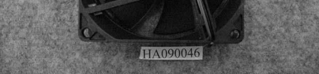
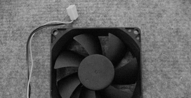
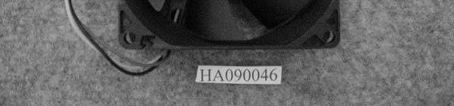
54 HongAn TECHNOLOGY CO., LTD. HA SAFD Page EUT Fan Front Side 18. EUT Fan Rear Side


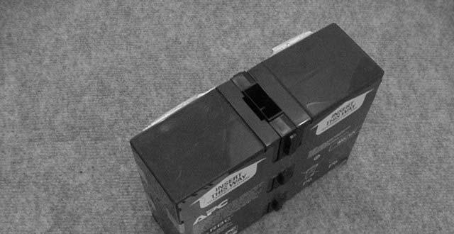

55 HongAn TECHNOLOGY CO., LTD. HA SAFD Page EUT Battery Front Side 20. EUT Battery Rear Side

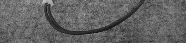
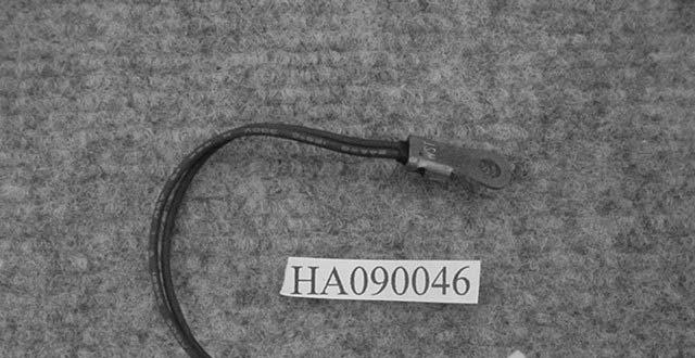
56 HongAn TECHNOLOGY CO., LTD. HA SAFD Page EUT Sensor Front Side 22. EUT Sensor Rear Side


57 HongAn TECHNOLOGY CO., LTD. HA SAFD Page EUT Battery Box Front Side 24. EUT Battery Box Rear Side


58 HongAn TECHNOLOGY CO., LTD. HA SAFD Page EUT Battery Box Inner View Front Side 26. EUT Battery Box Inner View Rear Side


59 HongAn TECHNOLOGY CO., LTD. HA SAFD Page EUT Battery Front Side For Battery Box 28. EUT Battery Rear Side For Battery Box
HongAn TECHNOLOGY CO., LTD. Report Number: HA VI i
 HongAn TECHNOLOGY CO., LTD. Report Number: HA070021-VI i Table of Contents Page Total Page 8 1. General Information 1-1 1.1 Product Information..... 1-2 1.2 Test Methodology.... 1-4 1.3 Test Facility.
C E R T I F I C A T I O N
 C E R T I F I C A T I O N Applicant Address Manufacturer Address : American Power Conversion Holding Inc. Taiwan Branch : 3F., No. 205, Sec. 3, Beixin Rd., Xindian Dist., New Taipei City 231, Taiwan R.O.C.
C E R T I F I C A T I O N
 C E R T I F I C A T I O N Applicant Address Manufacturer Address :American Power Conversion Holding Inc. Taiwan Branch :3F., No. 205, Sec. 3, Beixin Rd., Xindian Dist., New Taipei City 231, Taiwan R.O.C.
EMC COMPLIANCE TEST REPORT
 EMC COMPLIANCE TEST REPORT Technical Statement of Conformity in accordance with the council directive 2004/108/EC The product Equipment Under Test Model Number Product Series Report Number Issue Date Test
C E R T I F I C A T I O N
 C E R T I F I C A T I O N Applicant Address Manufacturer Address : American Power Conversion Holding Inc. Taiwan Branch : 3F., No. 205, Sec. 3, Beixin Rd., Xindian Dist., New Taipei City 231, Taiwan R.O.C.
C E R T I F I C A T I O N
 C E R T I F I C A T I O N Applicant Address Manufacturer Address : American Power Conversion Holding Inc. Taiwan Branch : 3F., No. 205, Sec. 3, Beixin Rd., Xindian Dist., New Taipei City 231, Taiwan R.O.C.
T A B L E O F C O N T E N T S DESCRIPTION PAGE
 TABLE OF CONTENTS DESCRIPTION PAGE 1. CERTIFICATION... 3 2. SUMMARY OF TEST RESULTS... 4 3. GENERAL INFORMATION... 5 3.1 PRODUCTION DESCRIPTION... 5 3.2 TEST MODES & EUT COMPONENTS DESCRIPTION... 5 3.3
FCC CLASS B COMPLIANCE REPORT (DoC)
") FCC CLASS B COMPLIANCE REPORT (DoC) for Electromagnetic Emissions Of ENTRY LEVEL IP PHONE Trade Name : XONTEL Model Number : XT-19P Serial Number : N/A Report Number : PZD1611741-F Date : Regulations :
FCC CLASS B COMPLIANCE REPORT (DoC) for Electromagnetic Emissions Of ENTRY LEVEL IP PHONE Trade Name : XONTEL Model Number : XT-19P Serial Number : N/A Report Number : PZD1611741-F Date : Regulations :
FCC 47 CFR PART 15 SUBPART B TEST REPORT. For. External USB 2.0 HDD Enclosure
 FCC 47 CFR PART 15 SUBPART B TEST REPORT For External USB 2.0 HDD Enclosure Model: AV300, AV500, LD300; AP35USL; EN318UHCR; EMV18BK; EMV18SL; EMV25BK; EMV25SL; EMV35BK; EMV35DBK; EMV35DSL; EMV35SL; ENAP25C;
FCC Part 15 Subpart B
 Report No.: 15A111603E-F Page 1 of 23 Test Report FCC Part 15 Subpart B for Electromagnetic Interference of Product: Managed PoE Industrial Ethernet Switch Trade Name: N/A Model Number: IS-DG512P-2F-8;
C-Tick EMC TEST REPORT. For. AC/DC Switching Power Supply
 C-Tick EMC TEST REPORT For AC/DC Switching Power Supply Model: CP0515(5V/1.5A); CP0520(5V/2A); CP0530 (5V/3A); CP0540 (5V/4A); CP0550 (5V/5A); CP0560 (5V/6A);CP0615(6V/1.5A); CP0620(6V/2A); CP0625 (6V/2.5A);
TEST REPORT. Table of Contents
 Page:2 of 28 Table of Contents 1. DOCUMENT POLICY AND TEST STATEMENT... 3 1.1 DOCUMENT POLICY... 3 1.2 TEST STATEMENT... 3 2. DESCRIPTION OF EUT AND TEST MODE... 4 2.1 GENERAL DESCRIPTION OF EUT... 4 2.2
TEST REPORT. Table of Contents
 Page:2 of 24 Table of Contents 1. DOCUMENT POLICY AND TEST STATEMENT... 3 1.1 DOCUMENT POLICY...3 1.2 TEST STATEMENT...3 2. DESCRIPTION OF EUT AND TEST MODE... 4 2.1 GENERAL DESCRIPTION OF EUT...4 2.2
FCC 47 CFR PART 15 SUBPART B
 FCC 47 CFR PART 15 SUBPART B TEST REPORT For DC TO DC CONVERTER Model : D100 Series Issued for MicroPower Direct, LLC 232 Tosca Drive Stoughton, MA02072 U.S.A. Issued by Compliance Certification Services
VCCI TEST REPORT. According to. V-3/ , TECHNICAL REQUIREMENTS, Class B ITE. Equipment : USB video camera. Model No. : V-U0017 / V-U0021
 VCCI TEST REPORT According to V-3/2009.04, TECHNICAL REQUIREMENTS, Class B ITE Equipment : USB video camera Model No. : V-U0017 / V-U0021 Applicant : Logitech Far East Ltd. 2 Creation Road IV, Science-Based
EMC TEST REPORT. REGULATORY MODEL NUMBER: REPORT NUMBER: TAO09046 ISSUED DATE: April 03, 2009
 Report Number: TAO09046 Page 1 of 22 EMC TEST REPORT REGULATORY MODEL NUMBER: 25152 REPORT NUMBER: TAO09046 ISSUED DATE: April 03, 2009 Applicant: LSI Corp 6145-D NORTHBELT PKY, NOR CROSS, GA 30071, USA
Declaration of Conformity (DoC)
") Declaration of Conformity (DoC) Per 47 CFR 2.1077(a) & 15.19(a)(3) The following device is herewith confirmed to comply with Part 15 of the FCC Rules. Product Name : PCIE-USB380,PCIE-USB340 Model No. :
Declaration of Conformity (DoC) Per 47 CFR 2.1077(a) & 15.19(a)(3) The following device is herewith confirmed to comply with Part 15 of the FCC Rules. Product Name : PCIE-USB380,PCIE-USB340 Model No. :
FCC 47 CFR PART 15 SUBPART B TEST REPORT
 FCC 47 CFR PART 15 SUBPART B TEST REPORT for 19 Multimedia LCD Monitor MODEL: R19LXXX-IPXXXX (X=A~Z, a~z, 0 ~9, Blank or Slash) Test Report Number: 90406001-D Issued for Winmate Communication INC. 9F,
FCC CLASS B COMPLIANCE REPORT (DOC)
") Page : 1 of 17 FCC CLASS B COMPLIANCE REPORT (DOC) Test Report No. : EM/2003/20077 Applicant/Factory : Moxa Technologies Co., Ltd. Address of Applicant : Fl. 4, No. 135, Lane 235, Pao-Chiao Rd., Shing
Page : 1 of 17 FCC CLASS B COMPLIANCE REPORT (DOC) Test Report No. : EM/2003/20077 Applicant/Factory : Moxa Technologies Co., Ltd. Address of Applicant : Fl. 4, No. 135, Lane 235, Pao-Chiao Rd., Shing
VCCI TEST REPORT. According to. Class B ITE. Equipment : USB video camera
 VCCI TEST REPORT According to Class B ITE Equipment : USB video camera Model No. : V-U0011 Applicant : Logitech Far East Ltd. 2 Creation Road IV, Science-Based Ind. Park, Hsinchu, Taiwan. The test result
CERTIFICATE. Issued Date: Apr. 20, 2006 Report No.: 064L079-IT-US-P01V01
 CERTIFICATE Issued Date: Apr. 20, 2006 Report No.: 064L079-IT-US-P01V01 This is to certify that the following designated product Product : 19 inch Rack-mounted Data Acquisition Computer Trade name : Moxa
TEST SUMMARY Seite 2 von 19. Prüfbericht - Nr.: Test Report No.:
 10050333 001 Seite 2 von 19 Page 2 of 19 TEST SUMMARY 5.1 CONDUCTED EMISSION PER SECTION 15.107, FCC 47 CFR PART 15 SUBPART B RESULT: Pass 5.2 RADIATED EMISSION PER SECTION 15.109, FCC 47 CFR PART 15 SUBPART
FCC Test Report FCC ID: XN6-SB3651E6
 FCC Test Report FCC ID: XN6-SB3651E6 Product: Trade Mark: Model Number: Serial Model: Report No.: 36 Inch Sound Bar 5.1 System VIZIO SB3651-E6 N/A NTEK- 2017NT02221568F Prepared for Zylux Acoustic Corporation
FCC PART 15, CLASS B MEASUREMENT AND TEST REPORT. NanJing JingZe Lighting Technology Co.,Ltd
 FCC PART 15, CLASS B MEASUREMENT AND TEST REPORT For NanJing JingZe Lighting Technology Co.,Ltd No. 30, Hengfa Rd., National Economic Technological Development Zone, Nanjing, Jiangsu, China Tested Model:
Gestek GESTEK Gestek
 February 2008 WinMate Gestek Communications GESTEK INC. Gestek Product Type : 12.1 Panel PC Gestek GESTEK Gestek Model Number : R12Ix7T-xxxx (x=a~z, a~z, 0~9, blank) Brand Name : WinMate estek GESTEK Gestek
CERTIFICATE. Issued Date: Apr. 02, 2009 Report No.: R-ITUSP01V01
 CERTIFICATE Issued Date: Apr. 02, 2009 Report No.: 093337R-ITUSP01V01 This is to certify that the following designated product Product : 2G 8/16PORT Serial Device Server Trade name : Moxa Model Number
Neutron Engineering Inc.
 Declaration Neutron represents to the client that testing is done in accordance with standard procedures as applicable and that test instruments used has been calibrated with the standards traceable to
APPLICATION FOR CERTIFICATION On Behalf of Futaba Corporation Radio Control Model No.:T10CG-2.4G FCC ID:AZPT10CG-24G Brand : Futaba
 FCC ID. AZPT10CG-24G Page 1 of 56 APPLICATION FOR CERTIFICATION On Behalf of Futaba Corporation Radio Control Model No.:T10CG-2.4G FCC ID:AZPT10CG-24G Brand : Futaba Prepared for : Futaba Corporation 1080
FCC 47 CFR PART 15 SUBPART B TEST REPORT
 FCC 47 CFR PART 15 SUBPART B TEST REPORT for 10.4 Rugged Tablet PC Model: R10V28M-VMXXXX (X=A~Z, a~z, 0 ~9, Blank or Slash) Test Report Number: 80808002-D Issued for Winmate Communication INC. 9F, No.
STC Test Report. Date: Page 2 of 25 No.: MH The Hong Kong Standards and Testing Centre Ltd.
 Date: 2013-05-22 Page 2 of 25 CONTENT: Cover Page 1 of 25 Content Page 2 of 25 1.0 General Details 1.1 Equipment Under Test [EUT] Page 3 of 25 Description of sample(s) 1.2 Description of EUT operation
Application for FCC Certificate On Behalf of LG Electronics U.S.A., Inc. LCD Monitor. Model No.: E2242VA. Serial No.
 LG Electronics U.S.A., Inc. FCC ID: BEJE2242VA Page 1 of 42 Application for FCC Certificate On Behalf of LG Electronics U.S.A., Inc. LCD Monitor Model No.: E2242VA Serial No.: E1203277-01/01 FCC ID : BEJE2242VA
Neutron Engineering Inc.
 Declaration Neutron represents to the client that testing is done in accordance with standard procedures as applicable and that test instruments used has been calibrated with the standards traceable to
Test Report. Applicant ASUSTeK COMPUTER INC. 4F, No. 150, Li-Te Rd., Peitou, Taipei, Taiwan. Date of Receipt Jan. 28, Issued Date Mar.
 Test Report Product Name Model No. FCC ID. IC ID. WPC Qi 1.1/1.0 compliance wireless charging micro-usb box Wireless Charger MSQ-ASUSWLCHARGER 3568A-ASWLCHARGER Applicant ASUSTeK COMPUTER INC. Address
REVISION HISTORY. The revision history for this document is shown in table. HCT-EM-1801-FC037 January 22, 2018 Initial Release
 REVISION HISTORY The revision history for this document is shown in table. Version Issue Date Description HCT-EM-1801-FC037 January 22, 2018 Initial Release HCT-EM-1801-FC037-R1 January 26, 2018 Revision
Test Report. Product Name: Cable Modem Model No.: BEFCMU10 ver.3 FCC ID. : Q87-BEFCMU10V3
 Report No. 036H064FI Test Report Product Name: Cable Modem Model No.: BEFCMU10 ver.3 FCC ID. : Q87-BEFCMU10V3 Applicant : Cisco-Linksys, LLC Address : 17401 Armstrong Avenue, Irvine, CA 92614 USA Date
APPROVED BY: DATE: 19-Aug-2011 Brian Boyea, EMC Engineer. TESTED BY: DATE: 12-Aug-2011 Arturo Ruvalcaba, EMC Engineer
 ENGINEERING TEST REPORT NUMBER: 102127174EUS1 ON Model No.(s): MAVRK IN ACCORDANCE WITH: CFR 47, PART 15, SUBPART B, TESTED FOR: Texas Instruments, Inc. 12500 TI Boulevard MS 8712 Dallas TX 75243 TESTED
To «Test_Standards» Test of: Radwin Ltd. Outdoor Subscriber Radio Unit. To: FCC CFR 47 Part 15B; ICES-003 Issue 6: 2016
 TEST REPORT ADDENDUM Part 15B & ICES-003 FROM To «Test_Standards» Test of: FCC CFR 47 Part 15B; ICES-003 Issue 6: 2016 Test Report Serial No.: Issue 13 th July 2016 Master Document Number RDWN41 U5 _Master
APPLICATION FOR VERIFICATION On behalf of MATRIX LIGHTING LTD. LED spot light. Model No.: 50-45GUS 50-45EUS Serial No.: E /02 E /02
 Page : 1 of 26 APPLICATION FOR VERIFICATION On behalf of MATRIX LIGHTING LTD. LED spot light Model No.: 50-45GUS 50-45EUS Serial No.: E1103090-01/02 E1103090-02/02 Prepared For : MATRIX LIGHTING LTD. ROOM
FCC Part 15B TEST REPORT
 S T S FCC Part 15B TEST REPORT Report No: STS1607009E01 Issued for Mobile commodity corporation 20955 pathfinder road, Suite 200, Diamond bar, CA 91765 L Product Name: GSM phone A Brand Name: Cellacom
TABLE OF CONTENTS. 6. PHOTOGRAPH Photo of Conducted Emission Measurement Photo of Radiation Emission Measurement...
 TABLE OF CONTENTS 1. SUMMARY OF TEST RESULTS... 4 2. GENERAL INFORMATION... 5 2.1 Details of E.U.T.... 5 2.2 Description of Support Device... 6 2.3 Block Diagram of Test Setup... 6 2.4 Test Facility...
Report No.: 063L107-RF-CE-P14V02-2. Test Report. MICRO-STAR INTL Co., LTD. No. 69, Li-De St., Jung-He City, Taipei Hsien, Taiwan, R.O.C.
 Test Report Product Name Model No. Wireless LAN Card MS-6877 Applicant Address MICRO-STAR INTL Co., LTD. No. 69, Li-De St., Jung-He City, Taipei Hsien, Taiwan, R.O.C. Date of Receipt June 14, 2006 Issued
Test Report. Product Name : IPC Model No.
 Test Report Product Name : IPC Model No. : On Demand Switch 3 (RODS3-DEFAULT) On Demand Switch 3 (RODS3-S1-DEFAULT) On Demand Switch 3 (RODS3-S2-DEFAULT) Applicant : Radware Ltd. Address : 22 Raoul Wallenberg
Equipment : UPS Brand Name : Test Model No. : SRT3000RMXLW-IEC Multiple Listing :
 Equipment : UPS Brand Name : Test Model No. : SRT3000RMXLW-IEC Multiple Listing : SRT3000RMXLTxxxxxxxxxx SRT (means series name) 3000 (means maximum VA output) RM (means Rack Mounted) or none (means Tower
FCC Verification TEST REPORT
 FCC Verification TEST REPORT Product: 5 in 1 Environment Meter Model no.: ET-965 Trade Mark: N/A Report No.: TCT140915E005 Issued Date: Sep. 22, 2014 Issued for: Shenzhen Flus Technology Co., Ltd 3rd Floor,
STC Test Report. The Hong Kong Standards and Testing Centre Ltd.
 Date: 2011-11-15 Page 2 of 15 CONTENT: Cover Page 1 of 15 Content Page 2 of 15 1.0 General Details 1.1 Equipment Under Test [EUT] Page 3 of 15 Description of sample(s) 1.2 Description of EUT operation
TEST REPORT. Table of Contents
 Page:2 of 43 Table of Contents 1. DOCUMENT POLICY AND TEST STATEMENT... 4 1.1 DOCUMENT POLICY... 4 1.2 TEST STATEMENT... 4 2. DESCRIPTION OF EUT AND TEST MODE... 4 2.1 GENERAL DESCRIPTION OF EUT... 4 2.2
FCC DoC TEST REPORT. TESTED : Sep. 01 to 02, 2010 APPLICANT : LOGITECH FAR EAST LTD.
 FCC DoC TEST REPORT REPORT NO. : FD990901E04 MODEL NO. : Y-R0016 RECEIVED : Sep. 01, 2010 TESTED : Sep. 01 to 02, 2010 ISSUED DATE : Sep. 07, 2010 APPLICANT : LOGITECH FAR EAST LTD. ADDRESS : #2 Creation
FCC & RSS-216 (Class II Permissive Change) Wireless Power Transfer Report. for A Acer Incorporated
 Wireless Power Transfer Report. for A Acer Incorporated") Page 1 of 17 FCC 15.209 & RSS-216 (Class II Permissive Change) Wireless Power Transfer Report for A Acer Incorporated 8F., No.88, Sec. 1, Xintai 5th Rd., Xizhi, New Taipei City 22181, Taiwan (R.O.C) Product
Page 1 of 17 FCC 15.209 & RSS-216 (Class II Permissive Change) Wireless Power Transfer Report for A Acer Incorporated 8F., No.88, Sec. 1, Xintai 5th Rd., Xizhi, New Taipei City 22181, Taiwan (R.O.C) Product
FCC Test Report. Report No.: AGC FE01 2AAP6UB15MSKB. Attestation of Global Compliance (Shenzhen) Co., Ltd
 Co., Ltd") Page 1 of 24 FCC Test Report Report No.: AGC03052141001FE01 FCC ID 2AAP6UB15MSKB PRODUCT DESIGNATION : Keyboard BRAND NAME : N/A MODEL NAME : UB-15MSKB CLIENT : Shenzhen Zowee Technology Co., Ltd. DATE
Page 1 of 24 FCC Test Report Report No.: AGC03052141001FE01 FCC ID 2AAP6UB15MSKB PRODUCT DESIGNATION : Keyboard BRAND NAME : N/A MODEL NAME : UB-15MSKB CLIENT : Shenzhen Zowee Technology Co., Ltd. DATE
TEST REPORT To: - ABO ELECTRONICS (SHENZHEN) CO., LTD Block B3, Haocheng Industrial Park, Hexiu West Rd, Heping Village, Fuyong, Baoan, Shenzhen
 CO., LTD Block B3, Haocheng Industrial Park, Hexiu West Rd, Heping Village, Fuyong, Baoan, Shenzhen") To: TEST REPORT No.: (5216)033-0360(A) PARTICLE INDUSTRIES, INC TEST REPORT To: - Attn: Eric Attn: - Address: 1400 Tennessee St, #4 San Francisco, CA Address: - 94107 Fax: -- Fax: - E-mail: -- E-mail:
To: TEST REPORT No.: (5216)033-0360(A) PARTICLE INDUSTRIES, INC TEST REPORT To: - Attn: Eric Attn: - Address: 1400 Tennessee St, #4 San Francisco, CA Address: - 94107 Fax: -- Fax: - E-mail: -- E-mail:
ENGINEERING TEST REPORT
 ENGINEERING TEST REPORT NUMBER: 10216476EICES1 ON Model No.(s): BB-BONE-000 IN ACCORDANCE WITH: ICES-003, ISSUE 4: 2004 TESTED FOR: Circuitco Electronics 1380 Presidential, Suite 100 Richardson, Texas
Test Report. Product Name: Wireless 11g USB Adapter Model No. : MS-6826, UB54G FCC ID. : DoC
 Test Report Product Name: Wireless 11g USB Adapter Model No. : MS-6826, UB54G FCC ID. : DoC Applicant : MICRO-STAR INT L Co., LTD Address : No 69, Li-De st., Jung-He City, Taipei Hsien, Taiwan, R.O.C Date
FCC CFR47 PART 15 SUBPART C INDUSTRY CANADA RSS-GEN AND RSS-210 CERTIFICATION TEST REPORT FOR BROADCOM BLUETOOTH MODULE MODEL NUMBER: BCM92046MD
 FCC CFR47 PART 15 SUBPART C INDUSTRY CANADA RSS-GEN AND RSS-210 CERTIFICATION TEST REPORT FOR BROADCOM BLUETOOTH MODULE MODEL NUMBER: BCM92046MD IC #: 4324A-BRCM1029 REPORT NUMBER: 07U11199-1C ISSUE DATE:
ENGINEERING TEST REPORT NUMBER: EUS1. ON Model No.(s): MB-PRO-MVK, MCU-430F5438A-MVK, AFE-BREAKOUT-MVK, RF-BREAKOUT-MVK, & RF-TCA8418-MVK
: MB-PRO-MVK, MCU-430F5438A-MVK, AFE-BREAKOUT-MVK, RF-BREAKOUT-MVK, & RF-TCA8418-MVK") ENGINEERING TEST REPORT NUMBER: 10215290EUS1 ON Model No.(s): MB-PRO-MVK, MCU-430F5438A-MVK, AFE-BREAKOUT-MVK, RF-BREAKOUT-MVK, & RF-TCA8418-MVK IN ACCORDANCE WITH: CFR 47, PART 15, SUBPART B, TESTED FOR:
ENGINEERING TEST REPORT NUMBER: 10215290EUS1 ON Model No.(s): MB-PRO-MVK, MCU-430F5438A-MVK, AFE-BREAKOUT-MVK, RF-BREAKOUT-MVK, & RF-TCA8418-MVK IN ACCORDANCE WITH: CFR 47, PART 15, SUBPART B, TESTED FOR:
TEST REPORT To: - ABO ELECTRONICS (SHENZHEN) CO., LTD Block B3, Haocheng Industrial Park, Hexiu West Rd, Heping Village, Fuyong, Baoan, Shenzhen
 CO., LTD Block B3, Haocheng Industrial Park, Hexiu West Rd, Heping Village, Fuyong, Baoan, Shenzhen") To: TEST REPORT No.: (5216)033-0357(A) PARTICLE INDUSTRIES, INC TEST REPORT To: - Attn: Eric Attn: - Address: 1400 Tennessee St, #4 San Francisco, CA Address: - 94107 Fax: -- Fax: - E-mail: -- E-mail:
To: TEST REPORT No.: (5216)033-0357(A) PARTICLE INDUSTRIES, INC TEST REPORT To: - Attn: Eric Attn: - Address: 1400 Tennessee St, #4 San Francisco, CA Address: - 94107 Fax: -- Fax: - E-mail: -- E-mail:
FCC/IC Test Report. : 2AOIMOMATA1 Equipment authorization required : SDoC IC ID
 FCC/IC Test Report Product Name : Analog GPS Speedometer Trade Name : Omata Model No. : one FCC ID. : 2AOIMOMATA1 Equipment authorization required : SDoC IC ID : 23478 OMATA1 Applicant : Haltian Products
FCC CFR47 PART 15 SUBPART C CERTIFICATION TEST REPORT FOR DUAL RADIO OUTDOOR ACCESS POINT MODEL NUMBER: AP-ONE FCC ID: SWX-AP1R2
 FCC CFR47 PART 15 SUBPART C CERTIFICATION TEST REPORT FOR DUAL RADIO OUTDOOR ACCESS POINT MODEL NUMBER: AP-ONE REPORT NUMBER: 04U3091-1 ISSUE DATE: JANUARY 07, 2005 Prepared for UBIQUITI NETWORKS 1111
FCC 47 CFR PART 15 SUBPART B CERTIFICATION TEST REPORT FOR a/b/g/n/ac 3X3 WLAN + Bluetooth Combo PCI-E Mini Card MODEL NUMBER: BCM94360CS
 FCC 47 CFR PART 15 SUBPART B CERTIFICATION TEST REPORT FOR 802.11a/b/g/n/ac 3X3 WLAN + Bluetooth Combo PCI-E Mini Card MODEL NUMBER: BCM94360CS FCC ID: QDS-BRCM1069 IC: 4324A-BRCM1069 REPORT NUMBER: 12U14668-5
FCC TEST REPORT Authorized under Declaration of Conformity
 FCC TEST REPORT Authorized under Declaration of Conformity according to 47 CFR FCC Rules and Regulations Part 15 Subpart B, Class B Digital Device Equipment Model No. Filing Type Applicant : IPC Bare Bone
FCC TEST REPORT. for. 47 CFR, Part 15, Subpart C. SPORTON International Inc.
 FCC TEST REPORT for 47 CFR, Part 15, Subpart C Equipment Trade Name Model No. FCC ID Filing Type Applicant : GamePad : Genius : Wireless G-12X : FSUGG0005 : Certification : KYE Systems Corp. No. 492, Sec.
FCC DOC TEST REPORT. According to. 47 CFR, Part 2, Part 15, CISPR PUB. 22, ICES 003 Issue 6
 FCC DOC TEST REPORT According to 47 CFR, Part 2, Part 15, CISPR PUB. 22, ICES 003 Issue 6 Applicant Address Equipment Model No. Trade Name : Panasonic India Pvt. Ltd. : 6th Floor, "SPIC BUILDING" Annexe,
FCC DoC TEST REPORT To: PARTICLE INDUSTRIES, INC To: - Attn: Eric Attn: - Address: 1400 Tennessee St, #4 San Francisco, CA Address: -
 FCC DoC TEST REPORT To: PARTICLE INDUSTRIES, INC To: - Attn: Eric Attn: - Address: 1400 Tennessee St, #4 San Francisco, CA Address: - 94107 Fax: -- Fax: - E-mail: -- E-mail: - Folder No.: BVCZ16FE005ETHS-B
FCC DoC TEST REPORT. ADDRESS : #2 Creation Rd. 4, Science-Based Ind. Park Hsinchu Taiwan, R.O.C.
 FCC DoC TEST REPORT REPORT NO. : FD981207H01 MODEL NO. : N-I0004 RECEIVED : Dec 07, 2009 TESTED : Dec. 08, 2009 ISSUED: Dec. 14, 2009 APPLICANT : LOGITECH FAR EAST LTD. ADDRESS : #2 Creation Rd. 4, Science-Based
FCC TEST REPORT. according to. 47 CFR FCC Rules and Regulations Part 15 Subpart B, Class B Digital Device. Equipment : IPC Bare Bone System
 FCC TEST REPORT Authorized under Declaration of Conformity according to 47 CFR FCC Rules and Regulations Part 15 Subpart B, Class B Digital Device Equipment : IPC Bare Bone System Model No. : JNF9QUXX-YYYY
Page: 1 of 20 EMC TEST REPORT EN55024:1998+A2:2003
 Page: 1 of 20 EMC TEST REPORT Reference No. Applicant : WT05060412 : Gembird Electronics Ltd. Equipment Under Test (EUT) : Product Name : Cable Standards Model No : UAS111-M, UAS111, UAS112 : EN55022:1998+A2:2003
TABLE OF CONTENTS. 6. PHOTOGRAPH Photo of Conducted Emission Measurement Photo of Radiation Emission Measurement...
 TABLE OF CONTENTS 1. SUMMARY OF TEST RESULTS... 4 2. GENERAL INFORMATION... 5 2.1 Details of E.U.T.... 5 2.2 Description of Support Device... 5 2.3 Block Diagram of Test Setup... 5 2.4 Test Facility...
according to AS/NZS :1999 Door Entry Alarm System YUAN HSUN ELECTRIC CO., LTD.
 according to AS/NZS 4251.1:1999 EQUIPMENT MODEL NO. APPLICANT Door Entry Alarm System DES-700 YUAN HSUN ELECTRIC CO., LTD. NO. 57, CHUNG HE RD., ZUO-YING DIST., KAOHSIUNG CITY 813, TAIWAN, R. O. C. TEST
Contents. Report No.: EMC-FCC-1985 Page: 2 of 26
 Page: 2 of 26 Contents 1. Applicant information...3 2. Laboratory information...4 3. Test system configuration...5 3.1 Operation environment...5 3.2 Measurement Uncertainty...6 4. Description of E.U.T...7
TEST REPORT. For RFID READER/WRITER. In conformity with. FCC CFR 47 Part15 Subpart C
 TEST REPORT For RFID READER/WRITER In conformity with FCC CFR 47 Part15 Subpart C Model: TR3XM-SD01 / TR3XM-SU01 / TR3XM-SN01 FCC ID: MK4TR3XM-SX01 Test Item: RFID READER/WRITER Report No: RY1203Z12R1
APPLICATION FOR CERTIFICATION On Behalf of. Philips Consumer Electronics Company. Digital Audio Player
 APPLICATION FOR CERTIFICATION On Behalf of Philips Consumer Electronics Company Digital Audio Player Model Number SA5225BT/37 Brand Name PHILIPS Prepared for : Philips Consumer Electronics Company 3029
FCC 15B Test Report. : BTv4.0 Dual Mode USB Dongle. Address : Thompson Ave. / Lenexa, Kansas / / USA
 FCC 15B Test Report Equipment Model No. Brand Name Applicant : BTv4.0 Dual Mode USB Dongle : BT820 : Laird Technologies : Laird Technologies Address : 11160 Thompson Ave. / Lenexa, Kansas / 66219 / USA
ELECTROMAGNETIC EMISSIONS COMPLIANCE REPORT
 Page: 1 of 54 ELECTROMAGNETIC EMISSIONS COMPLIANCE REPORT INTENTIONAL RADIATOR CERTIFICATION TO FCC PART 15 SUBPART C REQUIREMENT FULL MODULE APPROVE OF Product Name: Brand Name: Model Name: Model Differences:
FCC DoC TEST REPORT. ADDRESS : #2 Creation Rd. 4, Science-Based Ind. Park Hsinchu Taiwan, R.O.C.
 FCC DoC TEST REPORT REPORT NO. : FD990811E03 MODEL NO. : A-E0001 RECEIVED : Aug. 11, 2010 TESTED : Aug. 13 to 17, 2010 ISSUED DATE : Aug. 20, 2010 APPLICANT : LOGITECH FAR EAST LTD. ADDRESS : #2 Creation
Nemko-CCL, Inc West Alexander Street Salt Lake City, UT
 Nemko-CCL, Inc. 1940 West Alexander Street Salt Lake City, UT 84119 801-972-6146 Test Report Declaration of Conformity Test Of: MICRO-RM2.4-LB Test Specification: FCC PART 15, Subpart B ICES-003, Issue
Page 1 of 51 Report No.: T TEST REPORT FCC ID: 2AGJ5WAP-30. In Accordance with: FCC PART 15, SUBPART C : 2015 (Section 15.
 Page 1 of 51 Report No.: T1851663 01 TEST REPORT FCC ID: 2AGJ5WAP-30 Applicant Address : Gonsin Conference Equipment Co., Ltd : No.401-406,Block C, Idea Industry Park, No.41 Fengxiang Road, Shunde, Foshan,
FCC CFR47 PART 15 SUBPART C CERTIFICATION TEST REPORT FOR THE FUEL WEB, INC. GATEWAY MODULE MODEL: GWM-P-SHRF-1 FCC ID: PX5-GWM1001
 FCC CFR47 PART 15 SUBPART C CERTIFICATION TEST REPORT FOR THE FUEL WEB, INC. GATEWAY MODULE MODEL: GWM-P-SHRF-1 REPORT NUMBER: 04U2623-2 ISSUE DATE: APRIL 21, 2004 Prepared for THE FUEL WEB, INC. 21614
FCC PART 15C TEST REPORT FOR CERTIFICATION On Behalf of. Trade Name : Activision. Model Number: / FCC ID: XLU
 FCC PART 15C TEST REPORT FOR CERTIFICATION On Behalf of Activision Publishing, Inc USB Wireless Receiver for Wii & USB Wireless Receiver for PS3 Trade Name : Activision. Model Number: 83973791/84148791
QI HARDWARE INC. Ben NanoNote. Model: Ben NanoNote September Report No.: (This report supersedes NONE)
") QI HARDWARE INC. Ben NanoNote September 24 2009 Report No.: (This report supersedes NONE) Modifications made to the product : See page 6 This Test Report is Issued Under the Authority of: Andy.Hao Compliance
QI HARDWARE INC. Ben NanoNote September 24 2009 Report No.: (This report supersedes NONE) Modifications made to the product : See page 6 This Test Report is Issued Under the Authority of: Andy.Hao Compliance
Test Report: 5R Champlain Street Dieppe, New Brunswick Canada E1A 1P6. Model Number: Verification
 Test Report: 5R46150.1 Applicant: Equipment Under Test: Model Number: In Accordance With: Tested By: Nanoptix Inc. 699 Champlain Street Dieppe, New Brunswick E1A 1P6 Spill Proof Cuts SPC FCC 47 CFR Part
ENGINEERING TEST REPORT NUMBER: EUS1. ON Model No.(s): BB-BONE-000 IN ACCORDANCE WITH: CFR 47, PART 15, SUBPART B, CLASS B VERIFICATION
: BB-BONE-000 IN ACCORDANCE WITH: CFR 47, PART 15, SUBPART B, CLASS B VERIFICATION") ENGINEERING TEST REPORT NUMBER: 10216476EUS1 ON Model No.(s): BB-BONE-000 IN ACCORDANCE WITH: CFR 47, PART 15, SUBPART B, TESTED FOR: Circuitco Electronics 1380 Presidential, Suite 100 Richardson, Texas
ENGINEERING TEST REPORT NUMBER: 10216476EUS1 ON Model No.(s): BB-BONE-000 IN ACCORDANCE WITH: CFR 47, PART 15, SUBPART B, TESTED FOR: Circuitco Electronics 1380 Presidential, Suite 100 Richardson, Texas
FCC PART EMI MEASUREMENT AND TEST REPORT. Advanced Card Systems Ltd.
 FCC PART 15.225 EMI MEASUREMENT AND TEST REPORT For Units 2010-2013, 20th Floor, Chevalier Commercial Centre, 8 Wang Hoi Road, Kowloon Bay, Hong Kong Report Type: Original Report Product Type: Contactless
FCC Test Report. : FCC 47 CFR FCC Part 15 Subpart B
 APPLICANT EQUIPMENT BRAND NAME MODEL NAME FCC ID STANDARD CLASSIFICATION : HMD Global Oy : Smart Phone : NOKIA : TA-1004 : 2AJOTTA-1004 : FCC 47 CFR FCC Part 15 Subpart B : Certification The product was
FCC 15B Test Report. : ac/a/b/g/n + Bluetooth 4.2 module (please refer to section for more details.)
") FCC 15B Test Report Equipment Model No. Brand Name Applicant Address Standard : 802.11 ac/a/b/g/n + Bluetooth 4.2 module (please refer to section 1.1.1 for more details.) : ST60-2230C (please refer to
FCC 15B Test Report Equipment Model No. Brand Name Applicant Address Standard : 802.11 ac/a/b/g/n + Bluetooth 4.2 module (please refer to section 1.1.1 for more details.) : ST60-2230C (please refer to
TEST REPORT. Building 6, XinXinTian Industrial Park, XinSha Road, ShaJing, Baoan District, ShenZhen, China. Shenzhen Innokin Technology Co.
 TEST REPORT Applicant Address Shenzhen Innokin Technology Co., Ltd Building 6, XinXinTian Industrial Park, XinSha Road, ShaJing, Baoan District, ShenZhen, China Manufacturer or Supplier Address Product
FCC PART EMI MEASUREMENT AND TEST REPORT. Advanced Card Systems Ltd.
 FCC PART 15.225 EMI MEASUREMENT AND TEST REPORT For Units 2010-2013, 20th Floor, Chevalier Commercial Centre, 8 Wang Hoi Road, Kowloon Bay, Hong Kong Report Type: Original Report Product Type: Contactless
Nemko Canada Inc., 303 River Road, R.R. 5, Ottawa, Ontario, Canada, K1V 1H2
 www.nemko.com Nemko Canada Inc., 303 River Road, R.R. 5, Ottawa, Ontario, Canada, K1V 1H2 Report Number: Product Marketing Name: 123766-1TRFEMC Paycheck 4 Thermal Ticket Printer Test Specification: FCC
FCC TEST REPORT. according to. 47 CFR FCC Rules and Regulations Part 15 Subpart B, Class A Digital Device
 FCC TEST REPORT according to 47 CFR FCC Rules and Regulations Part 15 Subpart B, Class A Digital Device Equipment : In Vehicle Computer Model No. : VBOX-3200-XXXXX FCC ID : N/A Filing Type : Verification
ELECTROMAGNETIC EMISSIONS COMPLIANCE REPORT
 Page: 1 of 57 ELECTROMAGNETIC EMISSIONS COMPLIANCE REPORT INTENTIONAL RADIATOR CERTIFICATION TO FCC PART 15 SUBPART C REQUIREMENT OF Product name: Brand Name: Model Name: FCC ID: REPORT NO: Bluetooth Headset
Test Report. Product Name : WIRELESS ACCESS POINT
 Test Report Product Name : WIRELESS ACCESS POINT Model No. FCC ID : MMC543AHVN2-26 : TK4MMC2N28 Applicant : Compex Systems Pte Ltd Address : 135 Joo Seng Road, #08-01 PM Industrial Building Singapore 368363
TEST SUMMARY. Prüfbericht - Nr.: Test Report No FIELD STRENGTH OF FUNDAMENTAL RESULT: Passed % BANDWIDTH RESULT: Passed
 Seite 2 von 24 Page 2 of 24 TEST SUMMARY 5.1.1 FIELD STRENGTH OF FUNDAMENTAL RESULT: Passed 5.1.2 99% BANDWIDTH RESULT: Passed 5.1.3 SPURIOUS EMISSION RESULT: Passed 5.2.1 SPURIOUS EMISSION RESULT: Passed
IC Test Report. SPORTON INTERNATIONAL INC. No. 52, Hwa Ya 1 st Rd., Hwa Ya Technology Park, Kwei-Shan Hsiang, Tao Yuan Hsien, Taiwan, R.O.C.
 IC Test Report APPLICANT : Texas Instruments Incorporated EQUIPMENT : WiFi and Bluetooth Evaluation Board BRAND NAME : Texas Instruments MODEL NAME : WL1835MODCOM8B IC : 451I-WL1835COM STANDARD : ICES-003
Report No.: 11A080304E-E Page 1 of 35. CE Test Report. (Declaration of Conformity) for. Electromagnetic Compatibility.
 for. Electromagnetic Compatibility.") Report No.: 11A080304E-E Page 1 of 35 Test Report (Declaration of Conformity) for Electromagnetic Compatibility of Product: USB Oscilloscope Trade Name: N/A Model Number: DSO-U2400; DSO-U2200; DSO-U2100
Report No.: 11A080304E-E Page 1 of 35 Test Report (Declaration of Conformity) for Electromagnetic Compatibility of Product: USB Oscilloscope Trade Name: N/A Model Number: DSO-U2400; DSO-U2200; DSO-U2100
TEST REPORT. Issued for:
 TEST REPORT FCC ID: 2ACJAPLT76XXG Product: TABLET PC Model No.: PLT7650G, PLT7649G, PLT76XXG ( XX can be replaced by digital from 00 to 99 ) Trade mark: N/A Report No.: TCT150721E012 Issued Date: Aug.
No. 620 HuaYuan Commercial Center, No. 347 XiXiang Road,XiXiang Town, Bao An District, ShenZhen City Tel : Fax:
 No. 620 HuaYuan Commercial Center, No. 347 XiXiang Road,XiXiang Town, Bao An District, ShenZhen City Tel : +86-755-27912080 Fax: +86-755-27916936 FCC TEST REPORT Product name : 7PORT DUAL SUPPLY POE SWITCH
EMC TEST REPORT TEST REPORT NUMBER BQD 1647INF386 TEST REPORT DATE 5 December 2016 TEST REPORT VERSION 1.0 MANUFACTURER PRODUCT NAME PRODUCT MODEL
 EMC TEST REPORT TEST REPORT NUMBER BQD 1647INF386 TEST REPORT DATE 5 December 2016 TEST REPORT VERSION 1.0 MANUFACTURER PRODUCT NAME PRODUCT MODEL CONDITION OF EUT WHEN RECEIVED ISSUED TO ISSUED BY APC
FCC Test Report. Report No.: AGC FE08. Attestation of Global Compliance (Shenzhen) Co., Ltd
 Co., Ltd") Page 1 of 27 FCC Test Report Report No.: AGC01039170608FE08 FCC ID : PODTYT-X1U TYPE OF AUTHORIZATION : Certification APPLICATION PURPOSE : Original Equipment PRODUCT DESIGNATION : Analog Transceiver BRAND
Page 1 of 27 FCC Test Report Report No.: AGC01039170608FE08 FCC ID : PODTYT-X1U TYPE OF AUTHORIZATION : Certification APPLICATION PURPOSE : Original Equipment PRODUCT DESIGNATION : Analog Transceiver BRAND
FCC TEST REPORT Authorized under Declaration of Conformity
 FCC TEST REPORT Authorized under Declaration of Conformity according to 47 CFR, Part 2 and Part 15, Subpart B Class B Equipment Model No. Filing Type Applicant : WIRELESS 11B USB ADAPTER : UB11B, MS-6823
CE TEST CERTIFICATION
 according to Certification No.: E5NC004 European Standard EN 61000-6-4:2001 EN 61000-3-2: 2000, EN 61000-3-3:1995/A1:2001 and EN 61000-6-2:2001 ( IEC 61000-4-2:1995/A1:1998, IEC 61000-4-3: 1995/A1:1998,
TEST REPORT. The submitted sample of the above equipment has been tested for according to the requirements of the following standards:
 TEST REPORT Applicant Address Innokin Technology Co., Ltd Building 6, XinXinTian Industrial Park, XinSha Road, ShaJing, Baoan District, ShenZhen, China Manufacturer or Supplier Address Product Innokin
Test Report. Product Name : Wireless N Day/Night Home Network Camera Model No. : DCS-932, DCS-932L, DCS-930_A2, DCS-930L_A2 FCC ID.
 Test Report Product Name : Wireless N Day/Night Home Network Camera Model No. : DCS-932, DCS-932L, DCS-930_A2, DCS-930L_A2 FCC ID. : KA2CS932LA1 Applicant : D-Link Corporation Address : No.289, Sinhu 3rd