Instruction Manual. mercury SrS
|
|
|
- Arleen Grant
- 6 years ago
- Views:
Transcription


1 Instruction Manual mercury SrS
2 Dear customer, We are delighted that you have decided to purchase the PowerBox Mercury SRS power supply from our range. We hope you have many hours of pleasure and great success with your PowerBox Mercury SRS. Product description The PowerBox Mercury SRS is a new power management system which combines all the experience and findings we have gained over the last few years, together with customer requests, in a single compact unit. Never before has so much functionality been crammed into such a small space! The Mercury SRS is ideal for any application requiring an airborne system which provides an uncompromising level of high performance. Integral igyro, dual battery, dual receiving system, telemetry, door sequencer and servo matching are just a few of the highlights which this small, lightweight device provides. Introduction These instructions explain how to install the Mercury SRS in the model and set it up with the help of the Assistants. Working through the individual steps in the Assistants completes most of the programming for the model; all that remains is to set up the auxiliary functions and fine-tune the servos using the servo-match function. Naturally it is also possible to set up all the functions of the Mercury SRS manually, i.e. without using the Setup Assistant. All the menu points are explained individually in the latter part of these instructions. 1. USING THE UNIT FOR THE FIRST TIME Any pilot who has experience using a PowerBox will immediately feel at home with the method of operating the Mercury SRS. The device is operated in the usual way with the help of a menu system displayed on the OLED screen, and the ON / OFF switch. 2 PowerBox-Systems World Leaders in RC Power Supply Systems
3 1.1. Installing the Mercury SRS in the model The Mercury SRS must be screwed to a hard surface in the model, otherwise it is possible that the integral igyro will not work properly. If the mounting plate is large, it must be stiffened by the addition of cross-struts. Please note that the Mercury SRS must always be installed in the model at rightangles to the fuselage centreline. The actual orientation of the Mercury SRS is unimportant: it can be installed in any location which is at 90 to the direction of flight. The actual installed position is automatically detected later when the Assistant is invoked. The switch is mounted on the fuselage side. As is usual, the inside of the switch opening should be stiffened by adding a hardwood doubler to prevent serious vibration from reaching the switch; this is particularly important if the fuselage is made of GRP. In the case of scale models it is often undesirable to have an exposed switch on the outside, and for such applications we offer the MagSensor or the Magic Jeti Switch (only Jeti TX) as alternative methods of switching. Please note, however: the SensorSwitch is essential for programming the unit, and should always be accessible. The OLED screen can be installed in any location where it is clearly visible. If the standard cable (50 cm) is not long enough, we can supply extension leads Connections The first step in operating the PowerBox is to connect two batteries to it; the two packs should be of the same type and capacity. Connect the switch, the screen, both receivers (Spektrum system: four satellites) and the optional GPS II sensor using the patch-leads supplied in the set. The batteries can be either 2S LiPo, 2S LiIon, 2S LiFePo or 5S NiMH types. We recommend the use of PowerBox Batteries, which include integral electronic charge circuitry. If you intend to make up your own battery packs, please note that correct polarity is vital, as the unit does not include reverse polarity protection in order to avoid power losses. Connecting a battery with reversed polarity - no matter how briefly - will instantly destroy the voltage regulators in the PowerBox. 3


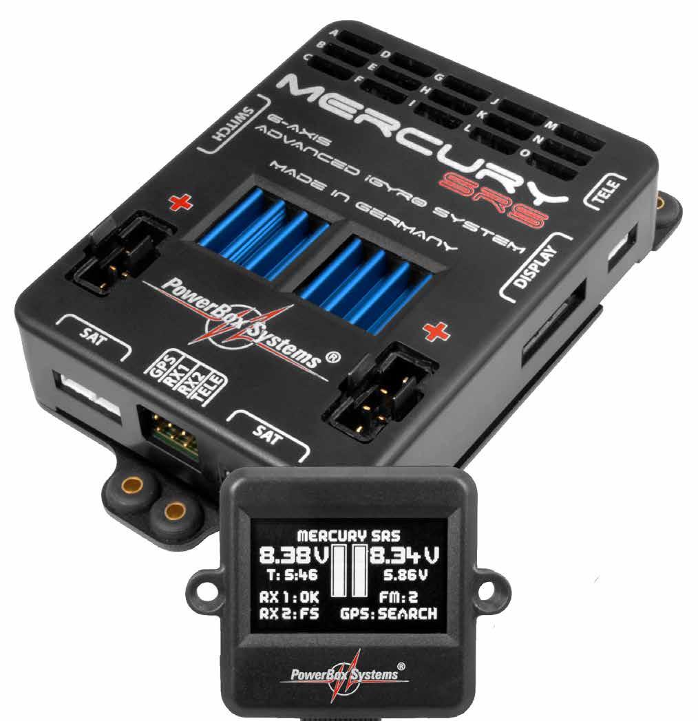
4 1.3. Switching on This is the procedure for switching the PowerBox on: hold the SET button pressed in, and wait until the orange LED on the switch lights up. Continue to hold the SET button pressed in while you briefly press buttons I and II; this completes the switching process. The OLED screen now displays the following: Digital battery display Flight time since the last reset Receiver status Output voltage igyro flight mode GPS status Voltage display in bar form showing also low voltage threshold to display voltage drops 2. CONNECTIONS, CONTROLS The following illustration shows the essential sockets and controls: SensorSwitch Spektrum telemetry Battery input 1 OLED screen GPS Receiver inputs Battery input 2 Spektrum satellites Telemetry and USB-Interface Adapter/BlueCom Adapter 4 PowerBox-Systems World Leaders in RC Power Supply Systems
5 3. MENU Hold the SET button pressed in for two or three seconds to enter the menu system; you can now move the cursor using buttons I and II. Hold the SET button pressed in once you have selected a particular menu point; you can then adjust values and settings using buttons I and II. 4. BASIC SETTINGS 4.1. Selecting the radio control system The Mercury SRS must be informed which radio control system you wish to use, as the bus systems of the various manufacturers differ very widely. You only need to enter this information once. The unit s integral SRS system selects one receiver when switched on, and automatically switches over to the second receiver if the signal is lost. Regardless of the type of radio control system employed, the change-over process takes just a few milliseconds, and is not noticeable to the pilot. The Mercury SRS can also be operated with a single receiver. Select the GENERAL SETTINGS point at the main menu, then press the SET button; the following screen display appears: At this point please select the radio control system you wish to use. With most receivers it is necessary to activate the Bus output, and / or set the correct operating mode. Bear in mind the following points: 5
6 - Futaba FASST and FASSTEST The Mercury SRS works with the S-BUS signal. Many receivers require one output to be re-assigned to S-BUS: R7003SB: no adjustment necessary; signal present at PORT 1. R7008SB: output 8 must be set to S-BUS, Mode B or Mode D. R6303SB: no adjustment necessary; direct S-BUS output fitted R6308SB(T): output 8 must be set to S-BUS, Mode B or Mode D. Other receivers with an S-BUS output can also be used; please refer to the set-up notes included in the instructions supplied with the receiver. Telemetry: if you wish to use telemetry, you will need the PowerBox Teleconverter, which is available as an optional extra. This is used to connect the TELE output on the PowerBox to the S-BUS 2 input of your receiver. - Spektrum DSM2 and DSMX If you have a Spektrum system you simply plug in three or four satellites, and all eighteen channels are available - without the need for an X-Plus module. Telemetry: if you wish your transmitter to receive telemetry data, you will need the Spektrum TM1000. Connect the three-pin TELE output of the PowerBox to the DATA input of the TM1000. Connect the four-pin TELE output of the PowerBox to the X-BUS input of the TM Jeti With a Jeti system it is only necessary to set one SAT or EXT output (depending on the particular receiver) to UDI 16. The remaining adjustments are carried out using the transmitter s device manager: Serial output: UDI Primary settings: Signal speed: 10 ms PPM settings: Direct Failsafe: Inactive (if two receivers are in use; otherwise any setting) Telemetry: if you wish your transmitter to receive telemetry data, connect the TELE output of the PowerBox to the EXT input of your satellite. 6 PowerBox-Systems World Leaders in RC Power Supply Systems
7 - Graupner HoTT When a HoTT system is used, the receivers should first be bound; adjustments can then be carried out in the Telemetry menu. All receivers require the CH-OUT-TYPE to be set to SUMD-OF-16. SUMD-OF-16 is present at Output 8. GR32: SUMD-OF-16 is present at Output S. Telemetry: if you wish your transmitter to receive telemetry data, connect the TELE output of the PowerBox to the T input of your receiver. - Multiplex M-LINK If you are using a Multiplex system, the B/D output at the receiver must be set to Serial Servo Data SRXL. This can be accomplished using the USB lead and the MPX Launcher PC program. If you connect two receivers, the following settings must also be entered: max. hold duration: 0.2 s and max. Failsafe duration: 0.0 s. Telemetry: if you wish your transmitter to receive telemetry data, connect the TELE output of the PowerBox to the SENSOR input of your receiver. - JR DMSS For a JR DMSS system you need receivers with an X-BUS output, e.g. RG- 731BX. The receiver or receivers are first bound, then set to MODE A at the transmitter. The X-BUS output now generates sixteen channels, which are accessible from the igyro SRS. Telemetry: if you wish your transmitter to receive telemetry data, connect the TELE output of the PowerBox to the SENSE input of your receiver Framerate At this point you can set the servo frame rate (signal repeat rate). If you are using modern digital servos, you can set a frame rate of ms, whereas older analogue servos may only work properly with a setting of 21 ms. If the frame rate is too low, you will notice that the servos jitter, or have no holding power at the centre position. 7
8 4.3. Battery type The battery type you wish to use is also determined in the GENERAL SET- TINGS menu. This setting is important, otherwise the battery display will not be correct Output voltage This is where you set your preferred output voltage: the available options are a regulated output voltage of either 5.9V or 7.4V. If you intend to use the 7.4V option, please ensure that all servos, switches and valves connected to the system are HV types, as the voltage is the same at all outputs. 5. SETUP ASSISTENT Once the basic settings are complete, you can move on immediately to the Setup Assistant, which can be found on the second page of the main menu. Start the Setup Assistant and follow the instructions on the screen. When you have concluded the settings on each screen display, press the SET button twice to move on to the next step. A single press of the SET button allows you to select BACK and return to the previous screen Installed position You will find the following screen displays in the SETUP ASSISTANT and also in the GENERAL SETTINGS menu under SET ORIENTATION: 1. At the first screen you are requested to raise or lower the model s tail. You can immediately determine whether the correct axis is selected by observing the elevator s response. If the elevator does not deflect, briefly jerk the model s tail up or down once. The PowerBox detects this movement, 8 PowerBox-Systems World Leaders in RC Power Supply Systems
9 causing the sensor to switch to the correct axis. Hold the model s tail at a slight angle, so that the bar deflects fully to the right, and wait until the elevator jumps back to the neutral position. The screen now switches automatically to the next display. 2. At this point you are requested to swing the model s tail to left or right: the rudder should immediately deflect in response to this movement. Here again: if the rudder does not respond, briefly jerk the model s tail once to left or right, so that the sensor switches to the correct axis. Now hold the model s tail far enough to left or right to cause the bar to move to full deflection, and wait until the rudder jumps back to the neutral position. This concludes the procedure, and the following screen display appears: You can install the Mercury SRS in any position, provided that the case is at right-angles (90 ) to the fuselage centreline Model type The next step is to select the model type which is the closest match to your aircraft. The main effect of your choice at this point is the assignment of the outputs. Take a look at the table below and decide which output assignment suits your model best: Note: it is also possible to change the output assignment at any time. 9
10 Explanation of terms: DS 1 5: VT: Door sequencer Vector thrust: thrust vector control The two model types Normal+VT and Delta+VT include a special feature as standard: in both cases the VT-RUDDER and VT-ELEVATOR outputs are switched off in flight modes 1 and 2. This allows you to control a jet with thrust vector control using only three channels, without having to set up mixers at the transmitter. You only need to set up aileron, elevator and rudder at the transmitter; thrust vector control is then switched on in flight mode 3. All outputs which are not assigned by the Assistant are marked -, indicating that they are free for use with other functions. 10 PowerBox-Systems World Leaders in RC Power Supply Systems
11 5.3. Flight mode switch Assign a three-position switch of your choice at the transmitter, and check that the travel is set to -100% to 0% to +100%. At a later point this switch will be used to call up the gyro functions you have already set. Move the switch once to all three positions in turn, and the channel will automatically be detected. If the flight modes are not in the arrangement (direction) you prefer, simply reverse that channel at the transmitter Gain channel The gain channel is only required for the test-flight, during which the gyro gain is adjusted to suit your model perfectly while it is in the air. Once the set-up flight is complete, this function is disabled automatically. Assign a rotary knob or slider to a vacant channel at the transmitter, and check that its travel is set to -100% to +100%. Move the rotary knob or slider to both end-points in turn, and the channel will be detected automatically. 11
12 5.5. Flight mode configuration The next stage is to define the gyro function required for each flight mode. This setting defines the task which the igyro is to carry out in flight modes 1, 2 and 3. Note that in flight mode 1 the Assistant only permits the functions OFF or RATE MODE. The following options are available: - OFF: The igyro is disabled. - RATE MODE: The igyro operates in Normal mode on all control surfaces. The gyro simply compensates for gusts of wind. - ATT ASSIST STD: Since the English terms Heading mode and Hold mode are not quite applicable to the way the igyro works, we have decided to adopt the name Attitude Assist Mode for its unique control characteristics. If the Attitude Assist Standard option is selected, the igyro maintains the model s attitude, as last commanded by the pilot, around the roll and pitch axes (aileron and elevator). At the same time the rudder operates in Normal mode, so that turns can be flown in the usual manner. The Attitude Assist Mode only operates at the neutral position of the sticks. As soon as the pilot gives a command, the igyro switches to Normal mode. The result is 100% natural handling in the air. This function is recommended for all models, and can be left active for take-off, flying and landing. The control characteristics of the igyro eliminate the need to worry about stalling, which can occur with conventional gyro systems. - ATT ASSIST ALL: This setting is identical to the above option, except that attitude maintenance is also active on rudder. This makes it easy to fly slow rolls, as the rudder automatically maintains the correct attitude. However, this flight mode option must not be used for normal flying, as the rudder would then try to maintain heading through aileron turns, making the model reluctant to turn. 12 PowerBox-Systems World Leaders in RC Power Supply Systems
13 - TORQUE ROLL: In this mode the igyro is capable of maintaining a model s attitude once it is brought into the vertical position. When this option is selected, all three gyro axes are turned up to 100%, and Heading mode is active. This flight mode must not be selected unless the model s forward speed is already close to zero. The torque roll is initiated as follows: you approach the manoeuvre by slowing the model down. The model is then rotated to the vertical position, and you activate the TORQUE ROLL option using the flight mode switch (usually FM3); you then adjust the throttle to maintain the model s height. The other control functions should be left untouched. If you now wish to rotate the model around the roll axis, you can do that by giving an aileron command, taking care not to touch rudder and elevator at the same time. When you wish to terminate the manoeuvre, remember to disable the TORQUE ROLL option using the flight mode switch before opening the throttle. - VECTOR THRUST: This option is specially tailored to suit model jets with thrust vector control. This flight mode option has several aspects: All gyro outputs including vector control are set to 100% gain. Attitude Assist is disabled. This is important with a jet, because there is no propwash over the control surfaces. The control functions for the assigned vector outputs (these are established later as part of the Assistant procedure) are activated. This means that rudder and elevator mixers must not be set up at the transmitter, as the Mercury SRS carries out these functions. When the flight mode option is disabled again, thrust vector control is restored to the neutral position which was detected when the PowerBox was first switched on. The Airspeed factor is set to a value of 5; this provides more time to switch flight modes as the model approaches and leaves the hover, without a tendency for the model to oscillate due to the high gain setting. The function is set up by accessing the appropriate flight mode using the flight mode switch, and selecting the desired function using buttons I and II on the SensorSwitch. 13
14 5.6. Teaching the aileron, elevator, rudder, landing flap and throttle functions During the following sequence of queries the Assistant assigns the channels to the appropriate functions as they arrive from the transmitter. The left-hand column shows the detected channel; in the centre is the function; the right-hand column shows the associated output of the Mercury SRS. You can immediately plug in your servos and check their operation. The Mercury also detects whether you are using, say, one or two channels for aileron or elevator. The outputs are assigned correctly according to the model type you selected earlier Direction of effect of the gyro outputs In the next two screen displays the gyro sensitivity (gain) is automatically set to maximum. You can now check the direction of effect of the gyro very simply by moving the model, and reverse the directions if necessary. The control surface must always deflect in the direction in which that part of the model is moved. Examples: - If you raise the tailplane, both elevators must deflect up. - If you raise the right-hand wing, the right-hand aileron must deflect up. - If you move the fin to the left, the rudder must deflect to the left. If you need to reverse the direction of gyro effect, move the cursor to the appropriate control surface and press the SET button. 14 PowerBox-Systems World Leaders in RC Power Supply Systems
15 This completes the Setup Assistant procedure. In the following stage all the remaining functions, such as retract system, brakes and lighting, are assigned and adjusted where necessary using the servo-matching function. 6. OUTPUT MAPPING Since the Setup Assistant does not cover all the functions, Output Mapping is employed to assign additional functions to the outputs; it is also possible to shift existing functions to other outputs. As can be seen in the screen-shot above, the left-hand column shows the output letter; the centre lists the assigned function or the transmitter channel; and the right-hand column is used to set each output to Hold or Failsafe if the radio link should fail. The following set-up facilities are provided for FUNCTION: - DIRECT 1 to 18: Depending on your radio control system, channels 1 to 18 can be output directly, as they arrive from the transmitter. Example: at your transmitter the wheel brakes are assigned to channel 9, and you wish to connect the brakes to output E. Move the cursor to E and confirm your choice by pressing the SET button. Set the following at E: DIRECT 9. The servo connected to output E now follows commands from channel 9 at your transmitter 1:1 - unless, that is, you have made adjustments using the servo-matching facility. - GY AILERON, ELEVATOR, RUDDER: If you select one of these functions, the output is linked internally with the igyro output. Two outputs are available for each axis: GY AILE-R, GY AI- LE-L, GY ELEV-R, GY ELEV-L, GY RUDD-A, GY RUDD-B. 15
16 Each of these axes is individually variable for gain, direction of effect and gyro function. Example: a) The right-hand aileron is connected to GY AILE-R, the left-hand aileron to GY AILE-L. b) The rudder is connected to GY RUDD-A, the steerable nosewheel to GY RUDD-B. - DOORS. 1 to 5: If you select one of these functions, the appropriate output is linked to the door sequencer. Which wheel door or valve is controlled by which door sequencer output is left entirely up to you, but we recommend using the Door Sequencer Assistant for the set-up process, as this will assign the outputs correctly. HD/FS: - FS (Failsafe): If a complete loss of signal occurs, affecting all receivers connected to the system, this output moves to a previously determined position. If you wish one or more outputs to take up a pre-determined position if the radio link fails, select the FS option for that output. At this point you should leave the OUTPUT MAPPING menu and select the GENERAL SETTINGS menu, where you will find the TEACH FAILSAFE PO- SITIONS menu point. Now use the transmitter controls to move all the control surfaces, the undercarriage and the throttle to the positions you want them to assume if a failsafe event is triggered, then press the SET button; this action stores the positions. You can test this setting simply by switching the transmitter off: the servos will immediately move to the positions you have just established. - HD (Hold): If a complete loss of signal occurs, affecting all receivers connected to the system, this output remains in the last good (known) position. 7. SERVOMATCHING The Servo-Match function provides the facility for adjusting the centreposition and end-points of the servos connected to the backer. If you have a model aircraft with more than one servo per control surface, this makes it 16 PowerBox-Systems World Leaders in RC Power Supply Systems
17 possible to set up multiple servos to move to identical positions at identical times. Since this ensures that the servos do not work against each other, their effective life is increased, and more power is available to move the control surfaces; matched servos also draw lower current. It is also possible to reverse the direction of rotation of individual servos. This function is useful if you wish to employ fewer channels at the transmitter. For example, the right and left elevators, or the right and left landing flaps, can be controlled using only one radio channel. In models such as jets and warbirds, which by their nature have a large number of working systems, this feature can be very important, but it can also make transmitter programming much easier with other types of model. Select SERVO-MATCHING in the Main menu, and the following screen display appears: To ensure accurate servo matching, the output to be adjusted must first be initialised. Leave the associated transmitter stick at centre. Move the cursor to INIT OUTPUT and press the SET button. Now move the transmitter stick to both end-points. The graphic display shows the movement of the upper arrow, which indicates the input signal. The bar inside the box shows the movement of the output. The three lower arrows indicate the centre and end-point positions which are learned in this process. Note: if the channel has not yet been initialised, it is not possible to select the START and REVERSE SERVO points. The following examples illustrate the correct procedure for the Servo-Match function: a) Fine-tuning multiple servos connected to a single control surface; in this example: right aileron connected to output A and output B - Disconnect the linkages from the unmatched servos, as they may exert damaging forces during the adjustment procedure! - First adjust the mechanical linkage of one servo (generally the inboard one, i.e. closer to the fuselage, connected to OUTPUT A), then - if necessary - adjust it at the transmitter, until the centre position and maximum endpoints are as you require. - Now select the channel to be fine-tuned in the servo-matching menu. In 17
18 this example it is OUTPUT B. - Leave the corresponding transmitter stick at the centre position. - Now select: INIT CHANNEL - Initialise the output by moving the transmitter stick to both end-points in turn. - Move the cursor to START SERVOMATCHING but do not press the SET button at this stage! - At the transmitter, move the aileron stick to the position to be adjusted, then press the SET button. - You can now release the aileron stick: the PowerBox maintains this position. You now have both hands free, and can adjust the position accurately with one hand, using buttons I and II, whilst checking the length (matching) of the disconnected ball-link at the horn with the other hand. - Press the SET button again to conclude this adjustment. - Complete the set-up procedure for the centre position and both end-points before re-connecting the servo linkage. - If you need to carry out further adjustments to another end-point or centre position, move the aileron stick in the desired direction again, and press the SET button again to start the procedure. - Repeat the procedure with all the servos connected to the same control surface. Note: if your model is fitted with very large ailerons, it can be advantageous not to match the servos with 100% accuracy. If the servos are precisely matched, gearbox play may allow aileron flutter to develop. You can eliminate this risk as follows: first match the servos exactly to each other, and then press buttons I or II two or three times to reduce the effect of lost motion in the servo gears to a controlled extent. b) Reversing one output where servos are installed in a mirror-image arrangement; in this example right and left landing flaps, connected to OUT E and OUT K - Disconnect the linkage to the left-hand landing flap, to avoid the servo being subjected to severe forces during the adjustment procedure. - The right-hand landing flap servo is connected to OUTPUT E; carry out the mechanical adjustment, then fine-tune it using the transmitter until the centre position and maximum end-points are correct. - Now select the channel to be matched in the servo-matching menu. In this example it is OUTPUT K. 18 PowerBox-Systems World Leaders in RC Power Supply Systems
19 - Move the landing flap switch to the center position - not one end-point! - Now select: INIT OUTPUT - The output is initialized by moving the switch on your transmitter to both end-points. If you have set up a delay at the transmitter, wait until the endpoint has been reached. - Use the SET button to select REVERSE SERVO. A tick appears after the function, and the left-hand landing flap servo now operates in the correct direction. - Move the cursor to START and press the SET button. - Use button I or II to adjust the center position of the left-hand landing flap to the exact position required, then press the SET button. - Move the transmitter switch to the flaps extended position, then press the SET button again. - Now set the appropriate end-point using button I or II before concluding the procedure with the SET button. - Move the transmitter switch to the retracted position, then press the SET button again. - Now set the corresponding end-point with button I or II, and conclude the procedure by pressing the SET button. - Both landing flaps will now move synchronously. 8. SETTING UP THE DOOR SEQUENCER Select the SEQUENCER point at the main menu; this takes you to the following screen display: The SETUP ASSISTANT helps you to adjust the gears and doors in a few minutes. The EXPERT MENU provides a very powerful programming interface, with which you can program highly individual sequences, or alternatively expand the settings previously entered using the SETUP ASSISTANT. More on this later. The SETUP ASSISTANT guides you through the settings: on-screen instructions describe everything that you have to do. These instructions simply provide supplementary information which cannot be supplied by the PowerBox itself simply due to the size of the screen. 19
20 The recommended programming procedure is as follows: first enter the basic settings using the SETUP ASSISTANT. At this point the system setup will be complete for 90% of all models. If you wish to add more wheel doors or adjust the sequence to cater for other details, this can be carried out in the EXPERT MENUE. Access the PowerBox s Door Sequencer menu, and select the SETUP ASSISTANT point. You will now see the following screen display: Operate the appropriate transmitter switch, and the PowerBox automatically detects it as the switch which you have assigned to the retract system. The on-screen arrows should now be located in front of UP/DOWN. If you find that your retract switch works in the wrong sense (direction), correct it by reversing that output at the transmitter. Press the SET button again to proceed. The door sequencer s method of working is determined in the following menu: The following sequences are available: Mode 1: Extend undercarriage: Open wheel doors extend undercarriage Retract undercarriage: Retract undercarriage close wheel doors Mode 2: Extend undercarriage: Open nosewheel doors extend nosewheel Open main wheel doors extend main undercarriage close main wheel doors 20 PowerBox-Systems World Leaders in RC Power Supply Systems
21 Retract undercarriage: Retract nosewheel Close nosewheel doors Open main wheel doors retract main undercarriage close main wheel doors Mode 3: Extend undercarriage: Open nosewheel doors extend nosewheel close nosewheel doors Open main wheel doors extend main undercarriage close main wheel doors Retract undercarriage: Open nosewheel doors retract nosewheel close nosewheel doors Open main wheel doors retract main undercarriage close main wheel doors Move the cursor to the appropriate mode, and press the SET button to confirm your choice. Select OK to move on to the next screen display: Connect your retract system valve to output C. One of the following will now occur, depending on the way your valve is programmed: a) Valve is triggered, and the undercarriage retracts. Press button II on your SensorSwitch, and hold it pressed in until the undercarriage extends again. b) Valve is not triggered, and the undercarriage remains in the extended state. Press the SET button twice to move to the next screen display: 21
22 The undercarriage should now retract. If not, hold button I pressed in until the valve is triggered, and the undercarriage retracts. Press the SET button to move on to the next stage of the procedure: Connect the servo for the first nosewheel door to output F. Use the SET button to close the first nosewheel door, then confirm by pressing the SET button. In the next screen display open the first nosewheel door again. The next steps are used to set up the second nosewheel door and the two rear wheel doors. The procedure is identical to that described for the nosewheel doors. Note: if you are only using one valve for all the wheel doors, you can skip the doors not required by selecting OK. Caution: the Door Sequencer Assistant overwrites the Output Mapping! Depending on the number of doors in your system, outputs C, F, I, L and O will be overwritten with door sequencer functions. All the settings are now complete, it will now take a few moments for the Assistant to create the necessary tasks, and move the doors to the correct position without any fouling or jamming. The tasks created by the Assistant are described in detail under Point 9.4. If the timing (pauses, opening times and closing times) is not exactly as you wish, you can change the settings manually at any time. You will find a range of examples of settings in our PowerBox Forum under FAQ. 22 PowerBox-Systems World Leaders in RC Power Supply Systems
23 9. TEST FLY ASSISTENT Once you have completed all the points listed above, it is time to carry out test-flights with the igyro. Even though the Mercury version of the igyro only requires one rotary knob or slider for the adjustment process, we recommend carrying out the procedure on the ground several times until you are confident that you know how to complete the process. Note that previous settings are overwritten every time you carry out this point. Just to be sure, please check the direction of effect of the gyro functions once more before you fly the model. From the main menu select the TEST FLY ASSISTANT point. The Mercury SRS carries out a self-calibration of the gyro sensors, and resets the maximum permitted control surface travels. In the next screen display you are requested to move all the transmitter sticks to both end-points. When you have done this, confirm by selecting OK. At the next screen you must move the flight mode switch to FM2, and set the gain control to 0%. As soon as you have done this, the Mercury SRS skips to the set-up screen display. 23
24 Launch the model and fly at half-throttle parallel with the landing strip. Increase gyro gain until the aircraft just starts to oscillate around one axis. At this point reduce gain slightly until the model shows no sign of oscillating in any speed range. Note: if you are using the Mercury SRS without GPS II, it is vital to ensure that the gain you set does not allow the model to oscillate even at full-throttle. Please take your time to complete this step properly! If the first level pass is too short to enable you to turn up the gain as far as you would like, simply carry out another pass. If you are not confident of doing this, ask a friend to adjust the gyro gain setting for you. If there is no wind at all when you carry out the set-up flights, it can be helpful to give the gyro a little work to do: briefly move the sticks away from centre to check that the model maintains its heading accurately, without any tendency to over-correct. The ideal test: set the model in the knife-edge attitude and adjust the rudder on its own to maintain a steady height; leave the aileron and elevator sticks alone. The model should now fly exactly straight, without any hint of oscillation. This final test is by no means essential, but it does provide a very clear demonstration of how effectively the igyro does its job! When you are sure that gyro gain is set correctly, move the flight mode switch to select FM1. This causes the igyro to adopt the previously selected gain setting, and also immediately adjusts your pre-defined igyro flight modes. Once you have done this, you are free to activate the flight mode you wish to use. Example: gain setting established during the set-up flight: 37%. These values are adopted for flight mode 2, while flight mode 1 and flight mode 3 are automatically adjusted by the Assistant based on your earlier inputs. FM1: GYRO OFF Aileron: 0% ATT.ASSIST: off Elevator: 0% ATT.ASSIST: off Rudder: 0% ATT.ASSIST: off 24 PowerBox-Systems World Leaders in RC Power Supply Systems
25 FM2: ATTITUDE ASSIST STD Aileron: 37% ATT.ASSIST: on Elevator: 37% ATT.ASSIST: on Rudder: 37% ATT.ASSIST: off FM3: TORQUE ROLL Aileron: 100% ATT.ASSIST: on Elevator: 100% ATT.ASSIST: on Rudder: 100% ATT.ASSIST: on The set-up procedure for your model is now complete. The following section explains all those functions which are available if you select the manual fine-tuning procedure. 10. ADDITIONAL FUNCTIONS AND SET-UP FACILITIES Flight recorder You can access the RF-Flight recorder display by briefly and simultaneously pressing buttons I and II on the Sensor- Switch: ANT. FADES: this item displays the lost data packets for the individual receivers or satellites. LOST FRAMES: this value shows the occasions when none of the receivers connected to the system was able to deliver a valid data packet. HOLDS: this value is incremented when none of the receivers connected to the system was able to supply a valid signal for a period longer than 250 ms. In this case the servos move to the Hold or Failsafe positions set in the PowerBox Flight time reset The main screen displays the elapsed flight time. You can use this timer to keep track of the power-on time, and reset it every time you recharge the batteries. The time is reset by simultaneously pressing buttons I and II on the SensorSwitch; hold both buttons pressed in until the screen displays the message RESET. 25
26 10.3. Gyro Settings The Gyro Settings menu permits you to adjust the gyro values manually. We recommend that you set up the igyro using the Setup Assistant and testfly the model using the Testfly Assistant; in the majority of cases it is likely that no further fine-tuning will be required. However, the following section describes the individual points in case you ever need to adopt non-standard settings. - AXIS: at this point you select the axis which is to be adjusted. The Mercury SRS offers six axes: Aileron-R, Aileron-L, Elevator-R, Elevator-L, Rudder-A and Rudder-B. - FM: here you select the flight mode which you intend to alter. The flight mode is selected using the transmitter switch you have already assigned (Input Mapping). - GAIN: this point displays the gain setting, which can be adjusted individually for each axis and each flight mode. If you find that gyro gain on one or other of the axes needs to be increased or reduced, you can simply fine-tune the value at this point using buttons I and II on the SensorSwitch. - ATT. ASSIST: Attitude Assist refers to Heading mode or Hold mode, as described earlier. It is possible to switch Attitude Assist on or off separately for each gyro axis. - DIRECTION: this item refers to the direction of effect of the gyro axis. If you are a newcomer to gyros, please note: the control surface must respond in the same direction as the part of the model which is moved. For example: if you raise the right-hand wing, the right-hand aileron must also deflect up. Caution: please don t confuse this with the direction in which the transmitter controls operate! It is vital to check the direction of gyro effect very carefully every time you make any adjustments to the igyro. 26 PowerBox-Systems World Leaders in RC Power Supply Systems
27 - AIRSPEED FACTOR: after the gyro test-flight the airspeed factor defaults to a value of 3. If you subsequently discover that the model starts to oscillate at high speed, but behaves perfectly at low speed, then you need to increase the airspeed factor. The higher the airspeed factor, the lower the gyro gain as the model s airspeed increases DOORSEQUENZER The door sequencer in the Mercury SRS provides completely unrestricted facilities for implementing control systems for retractable undercarriages and canopies. All sequences are controlled by means of TASKS. - SETUP ASSISTANT We recommend that you start the adjustment process using the SETUP ASSISTANT. This step-by-step guide to setting up the system presents the tasks in the appropriate order, automatically locates the channel for the retract switch, and assigns the door sequencer outputs in OUTPUT MAP- PING. The SETUP ASSISTANT is described under Point 5. - EXPERT MENUE If you work through the Assistant procedure and then find that some fine-tuning is desirable - perhaps in the timing of the sequence - you can make these changes in the EXPERT MENU: The TASK is the key to all adjustments. A Task can be defined as the movement of one servo from the start position to the stop position, with defined start and stop times. Twelve tasks are available for the retraction process, and a further twelve tasks for the extension process. This means that it is possible to program 24 different movement sequences. 27
28 A single Task contains the following information: Value Range Task number 1-12 Extend or retract undercarriage UP» DOWN / DOWN» UP Servo number 1 6 Servo START position 700µs 2300µs Servo STOP position 700µs 2300µs Start time s Stop time s Here is an example which demonstrates how the system works: UP» DOWN: all the tasks which you set up with this direction are carried out when the retract switch on the transmitter is moved to the Extend position. In our example we have selected door sequencer output 3. The servo runs from the START POSITION: 1152µs (right-hand servo end-point) to the STOP POSITION: 1830µs (left-hand servo end-point). The servo only starts moving 1.0 seconds after the switch is operated, and the transit time is 3.0s (difference between 1.0s and 4.0s). DOWN» UP: all the tasks which you set up with this direction are carried out when the retract switch on the transmitter is moved to the Retract position. In this example the servo immediately starts moving when the switch is operated (start time 0.0s), and moves from the left servo end-point (1830µs) to the right end-point (1152µs) within 3.0 seconds. 28 PowerBox-Systems World Leaders in RC Power Supply Systems
29 The positional values vary according to your linkages, and must therefore be set individually to suit the specific model. It is important to ensure that the wheel doors do not jam mechanically. The times stated in our example are also just an illustration, and need to be set to suit your preference. The timing of the tasks does not need to coincide with the task numbering. For example: it is permissible for Task 5 to occur before Task 2. Our example clearly shows how the function is built up. Additional movements or intervals between opening or closing the wheel doors can be inserted at any time; all you have to do is set up a new free task. This freedom is intended to remove all restrictions which might otherwise prevent the model s undercarriage retracting and extending in the exact scale manner. Important: the first START POSITION in the UP» DOWN sequence must always coincide with the last STOP POSITION in the DOWN» UP sequence. This means: intermediate steps can be made individually, but the final task must always take the servo back to its starting position! Caution: if you notice unusual or unexpected servo movements in the sequence, you need to check your tasks! - GEAR UP OUTPUT OFF: The door sequencer of the Mercury SRS includes a further auxiliary function which makes it possible to switch off a channel when the undercarriage is retracted. For example, the nosewheel should not deflect in parallel with the rudder when the undercarriage is in its retracted state, as this could jam the system mechanically; this function solves the problem. At this menu point simply enter the output which you wish to switch off as soon as the undercarriage is retracted. When you confirm your choice by pressing the SET button, the unit stores the position of the nosewheel which it is to adopt when the wheels are raised. Caution: once you have completed the set-up procedure, it is important to check all the model s control surface systems with the undercarriage both retracted and extended. For example, if you were accidentally to assign the GEAR UP OUTPUT OFF function to the elevator output, then your model would surely be wrecked immediately after take-off! 29
30 10.5. Input Mapping Modern SRS bus technology makes it possible to assign channels for particular functions without restriction. The quickest method of assigning the Input Mapping functions is to use the Setup Assistant, but it is also possible to assign them manually at this point. To assign a channel, use the SET button to select the appropriate function, then move the transmitter stick, rotary knob or switch which you wish to assign. Note: if more than one channel is assigned for a particular transmitter control (e.g. channels 2 and 6 for the ailerons), move the stick repeatedly away from centre and back again until the appropriate channel is selected. An alternative method is to assign the functions using buttons I and II General Settings Most of the points in the General Settings menu have already been explained in Point 4. Those not previously covered are explained below: - SET ORIENTATION: this is the point where the installed position of the Mercury SRS in the model is established. As in the Setup Assistant, all you have to do after selecting this menu point is raise or lower the model s tail. The on-screen bar shows when the angle of tilt is sufficient. Once the bar has filled to the right, you need to hold the model motionless; the process ends automatically once the PowerBox has unambiguously detected the unit s installed orientation. - Aircraft Type: this point is also normally carried out as part of the Setup Assistant process. Carrying it out in the General Settings menu resets the Output Mapping, which then reverts to the arrangement shown in the table in section PowerBox-Systems World Leaders in RC Power Supply Systems
31 - GYRO SENSE x4: This option quadruples the gyro effect; this is often necessary with large, sluggish models in order to obtain the optimum stabilizing effect. Caution: Select this option only if 100% gyro effect is inadequate! Selecting this option resets all gain settings to 0%! Re-start the Testfly Assistant, and fly the model again to establish the optimum values Factory Reset This option can be selected if you wish to reset the Mercury SRS to the factory default settings. You will see a security query whose purpose is to prevent an accidental reset PC-Control The PC-CONTROL option permits the Mercury SRS to be connected to a PC, a tablet or a mobile telephone. In this way you can load updates into the Mercury SRS to ensure that it constantly reflects the latest state of development. The following methods are available: a) Using the BlueCom Adapter (ios: 9021, Android: 9022), a mobile telephone and the free PowerBox Mobile Terminal App. You will find the Mobile Terminal App in your App Store. b) Using the USB Interface Adapter (9020), a PC and the PowerBox Terminal program. The PowerBox Terminal software is available as a free download from our website. Connect the BlueCom Adapter or the USB Interface Adapter to the Tele-Input. 31
32 11. SPECIFICATION Operating Voltage: 4,0V - 9,0V Battery type: 2s LiPo/LiIon, 2s LiFePo, 5s NiMH/NiCd Current drain (ON): approx. 99mA Current drain (OFF): approx. 3µA Output voltage regulated: 5,9V and/or 7,4V Max. output current: Peak 2 x 20A Dropout voltage: 0,3V Signal resolution: 0,5µs Output framerate: 12ms, 15ms, 18ms, 21ms Display: OLED 128x64 pixels, graphic Servo sockets: 15 Channels max. 18 Telemetrie: Futaba, Jeti, Spektrum, Hott, M-Link, JR DMSS Size: 93x67x19 mm Weight incl. Switch and screen: 115g Temperature range: -30 C to +75 C EMV approval: EN :2006 CE approval: 2004/108/EG 32 PowerBox-Systems World Leaders in RC Power Supply Systems
33 12. DIMENSIONS 33
34 13. SET CONTENTS - PowerBox Mercury SRS - OLED-Display - SensorSwitch - 3 Patchwires 3-pole, 200mm - 8 mounting screws - Operating instructions Optional: GPS Sensor 14. SERVICE NOTE We make every effort to provide a good service to our customers, and have now established a Support Forum which covers all queries relating to our products. This helps us considerably, as we no longer have to answer frequently asked questions again and again. At the same time it gives you the opportunity to obtain assistance all round the clock, and even at weekends. The answers come from the PowerBox team, which guarantees that the answers are correct. Please use the Support Forum before you contact us by telephone. You will find the forum at the following address: GUARANTEE CONDITIONS At PowerBox-Systems we insist on the highest possible quality standards in the development and manufacture of our products. They are guaranteed Made in Germany! That is why we are able to grant a 36 month guarantee on our PowerBox Mercury SRS from the initial date of purchase. The guarantee covers proven material faults, which will be corrected by us at no charge to you. As a precautionary measure, we are obliged to point out that we reserve the right to replace the unit if we deem the repair to be economically unviable. Repairs which our Service department carries out for you do not extend the original guarantee period. 34 PowerBox-Systems World Leaders in RC Power Supply Systems
35 The guarantee does not cover damage caused by incorrect usage, e.g. reverse polarity, excessive vibration, excessive voltage, damp, fuel, and short-circuits. The same applies to defects due to severe wear. We accept no liability for transit damage or loss of your shipment. If you wish to make a claim under guarantee, please send the device to the following address, together with proof of purchase and a description of the defect: SERVICE ADDRESS PowerBox-Systems GmbH Ludwig-Auer-Straße 5 D Donauwoerth Germany 16. LIABILITY EXCLUSION We are not in a position to ensure that you observe our instructions regarding installation of the PowerBox Mercury SRS, fulfil the recommended conditions when using the unit, or maintain the entire radio control system competently. For this reason we deny liability for loss, damage or costs which arise due to the use or operation of the PowerBox Mercury SRS, or which are connected with such use in any way. Regardless of the legal arguments employed, our obligation to pay compensation is limited to the invoice total of our products which were involved in the event, insofar as this is deemed legally permissible. We wish you every success with your new Mercury SRS. Donauwoerth, July
Instruction Manual. PowEr ExpAndEr srs
 Instruction Manual PowEr ExpAndEr srs Dear customer, we re delighted that you have chosen the PowerExpander SRS from our range of products. We hope you have great pleasure and success with this accessory!
Instruction Manual. EVolution
 Instruction Manual EVolution Dear customer, We are delighted that you have decided to purchase the PowerBox Evolution from our range. We wish you every success with your new PowerBox Evolution, and hope
Dear customer, 1. Product description
 Instruction Manual Dear customer, we are delighted that you have selected the LightBox SR from our range of products. We are confident that this unique lighting control unit will bring you much pleasure
Instruction Manual. GPS ii
 Instruction Manual GPS ii Dear customer, we are delighted that you have decided to purchase the GPS ll from our range. We hope you have many hours of pleasure and great success with your new GPS ll. 1.
Instruction Manual. PowErBox Cockpit PowErBox CompEtition PowErBox ProfEssionAl
 Instruction Manual PowErBox Cockpit PowErBox CompEtition PowErBox ProfEssionAl Dear customer, We are delighted that you have decided to purchase a power supply unit from PowerBox-Systems. We hope you have
Instruction Manual. PowErBox Cockpit SrS PowErBox CompEtition SrS
 Instruction Manual PowErBox Cockpit SrS PowErBox CompEtition SrS Dear customer, we are delighted that you have decided to purchase the PowerBox Cockpit/Competition SRS from our range. We hope you have
We are delighted that you have decided to purchase a power supply unit from PowerBox Systems.
 Dear customer, We are delighted that you have decided to purchase a power supply unit from PowerBox Systems. We hope you have many hours of pleasure and great success with your new PowerBox. 1. Product
07/2015. Instruction Manual
 07/2015 Instruction Manual Dear customer, We are delighted that you have decided to purchase the PowerBox Evolution from our range. We wish you every success with your new PowerBox Evolution, and hope
SpArk switch. Instruction Manual
 SpArk switch Instruction Manual Dear customer, We are delighted that you have decided to purchase the SparkSwitch from PowerBox-Systems. The SparkSwitch is a reliable high-performance ignition switch.
Introduction. Overview. Outputs Normal model 4 Delta wing (Elevon) & Flying wing & V-tail 4. Rx states
 & Flying wing & V-tail 4. Rx states") Introduction Thank you for purchasing FrSky S6R/S8R (SxR instead in this manual) multi-function telemetry receiver. Equipped with build-in 3-axis gyroscope and accelerometer, SxR supports various functions.
Introduction Thank you for purchasing FrSky S6R/S8R (SxR instead in this manual) multi-function telemetry receiver. Equipped with build-in 3-axis gyroscope and accelerometer, SxR supports various functions.
Operating Instructions
 Operating Instructions Operating Instructions Brief description of the PowerBox 40/24 Champion Petty patent No.: 203 13 420.6 This power supply system, based on the PowerBox Competition, offers a range
A3 Pro INSTRUCTION MANUAL. Oct 25, 2017 Revision IMPORTANT NOTES
 A3 Pro INSTRUCTION MANUAL Oct 25, 2017 Revision IMPORTANT NOTES 1. Radio controlled (R/C) models are not toys! The propellers rotate at high speed and pose potential risk. They may cause severe injury
Instruction Manual PREVIEW
 Instruction Manual PREVIEW Dear PowerBox pilot, Many thanks for placing your trust in us, and purchasing our PowerBox CORE. You have chosen an extremely unusual radio control system: the CORE has great
The igyro Simplified!
 The igyro Simplified! I have a confession. Frankly, I am an older person. As such, the common wisdom is that I should move slowly, complain a lot and struggle with new technology. Unfortunately, all three
CX-1X Mini Heading-Hold Gyro System. Copyright 2014 KY MODEL Company Limited.
 CX-1X2000 Mini Heading-Hold Gyro System INSTRUCTION MANUAL www.copterx.com Copyright 2014 KY MODEL Company Limited. MENU 1. 2. 3. 4. 5. 6. 7. 8. 9. 10. Table of content Introduction Features Specifications
Detrum MSR66A Receiver
 Motion RC User Guide for the Detrum MSR66A Receiver Version 1.0 Contents Review the Receiver s Features... 1 Review the Receiver s Ports and Connection Orientation... 2 Bind the Receiver to a Transmitter
Detrum GAVIN-8C Transmitter
 Motion RC Supplemental Guide for the Detrum GAVIN-8C Transmitter Version 1.0 Contents Review the Transmitter s Controls... 1 Review the Home Screen... 2 Power the Transmitter... 3 Calibrate the Transmitter...
User Manual Version 1.0
 1 Thank you for purchasing our products. The A3 Pro SE controller is the updated version of A3 Pro. After a fully improvement and optimization of hardware and software, we make it lighter, smaller and
Xtreme Power Systems X24. Integrated Flight Control System. Installation And Usage Manual
 Xtreme Power Systems X24 Integrated Flight Control System Installation And Usage Manual Supports: XtremeLink RFU and Nano receivers Futaba SBUS and SBUS2 receivers Spektrum DSM2/DSMX satellite receivers
Caution Notes. Features. Specifications. Installation. A3-L 3-axis Gyro User Manual V1.0
 Caution Notes Thank you for choosing our products. If any difficulties are encountered while setting up or operating it, please consult this manual first. For further help, please don t hesitate to contact
Smart Bus RRS. Quick Start Guide
 Smart Bus RRS Quick Start Guide Thank you for your purchase of the Advance Radio Smart Bus. In this quick start guide we will show you how to connect your new Smart Bus, General use and Set Up. Please
Smart Bus RRS. Quick Start Guide
 Smart Bus RRS Quick Start Guide Thank you for your purchase of the Advance Radio Smart Bus RRS. In this quick start guide we will show you how to connect your new Smart Bus, General use and Set Up. Please
X10+ Channel Expander (V2)
") Xtreme Power Systems X10+ Channel Expander (V2) Installation And Usage Manual Supports: XtremeLink RFU and Nano receivers Futaba SBUS and SBUS2 receivers Spektrum DSM2/DSMX satellite receivers JR DMSS
Xtreme Power Systems X10+ Channel Expander (V2) Installation And Usage Manual Supports: XtremeLink RFU and Nano receivers Futaba SBUS and SBUS2 receivers Spektrum DSM2/DSMX satellite receivers JR DMSS
Xtreme Power Systems
 Xtreme Power Systems XtremeLink NANO RECEIVER Installation And Usage Manual XtremeLink is a registered trademark of Xtreme Power Systems, LLC. Firmware v 1.9 Manual v 1.9 Revision Date: November 11 th,
Gyroscopic Landing Gear controller and sequencer GS-200. Users Guide.
 Gyroscopic Landing Gear controller and sequencer GS-200 Users Guide. Pol.Ind PPI-7, Parcela K, nave B9, O Porriño, Pontevedra, Spain E-mail: info@electron-retracts.com. web: www.electron-retracts.com Electron
Digiflight II SERIES AUTOPILOTS
 Operating Handbook For Digiflight II SERIES AUTOPILOTS TRUTRAK FLIGHT SYSTEMS 1500 S. Old Missouri Road Springdale, AR 72764 Ph. 479-751-0250 Fax 479-751-3397 Toll Free: 866-TRUTRAK 866-(878-8725) www.trutrakap.com
HM4050 AVCS HEADING LOCK GYRO
 INCLUDES HM4050 gyro with connectors Foam adhesive tape Manual HM4050 AVCS HEADING LOCK GYRO FEATURES AVCS (Angular Vector Control System) Small size Lightweight Able to operate in Heading Hold as well
Operating Handbook For FD PILOT SERIES AUTOPILOTS
 Operating Handbook For FD PILOT SERIES AUTOPILOTS TRUTRAK FLIGHT SYSTEMS 1500 S. Old Missouri Road Springdale, AR 72764 Ph. 479-751-0250 Fax 479-751-3397 Toll Free: 866-TRUTRAK 866-(878-8725) www.trutrakap.com
T14MZ Software Update Function Modification Contents (Version: 1.1.0, 1.2.0)
") T14MZ Software Update Function Modification Contents (Version: 1.1.0, 1.2.0) 1M23N14837 Hardware setting This function is for adjusting the sticks, switches and trim characteristics. [System menu] Swash
T14MZ Software Update Function Modification Contents (Version: 1.1.0, 1.2.0) 1M23N14837 Hardware setting This function is for adjusting the sticks, switches and trim characteristics. [System menu] Swash
Digiflight II SERIES AUTOPILOTS
 Operating Handbook For Digiflight II SERIES AUTOPILOTS TRUTRAK FLIGHT SYSTEMS 1500 S. Old Missouri Road Springdale, AR 72764 Ph. 479-751-0250 Fax 479-751-3397 Toll Free: 866-TRUTRAK 866-(878-8725) www.trutrakap.com
Post-Installation Checkout All GRT EFIS Models
 GRT Autopilot Post-Installation Checkout All GRT EFIS Models April 2011 Grand Rapids Technologies, Inc. 3133 Madison Avenue SE Wyoming MI 49548 616-245-7700 www.grtavionics.com Intentionally Left Blank
ARKBIRD-Tiny Product Features:
 ARKBIRD-Tiny Product Features: ARKBIRD System is a high-accuracy autopilot designed for fixed-wing, which has capability of auto-balancing to ease the manipulation while flying. 1. Function all in one
Trimming your Aerobatic Model
 Trimming your Aerobatic Model When we speak of trimming your aerobatic model we re not talking about trimming in the traditional sense of adjusting the control surfaces to maintain level flight. In this
Jet Central Sequencer Plus
 Jet Central Sequencer Plus Features The Jet Central Sequencer Plus is a multipurpose electronic device, the capabilities of the unit include: Three part sequencer, operating landing gear and two independent
REMOVE REAR OF TX-2S TO INSERT THE 9 VOLT BATTERY.
 P.O Box 578 Casino, NSW, 2470 Australia Phone: International ++614 2902 9083 Australia (04) 2902 9083 Website: http://rcs-rc.com E mail: Info@rcs-rc.com TX-2s Digital Proportional R/C TABLE OF CONTENTS
User Guide 3DIGI. Reloaded
 3DIGI Reloaded Version 1.1.0 Dirk Schmidt Index Preface... 3 Safety instructions... 4 Technical data... 5 Connections... 6 First start-up... 9 Installation... 9 Preparation of the transmitter... 10 Installation
Operating Instructions
 40/24 Operating Instructions Double voltage stabilisation with linear regulation and double battery monitor, double signal amplification for each channel, twin electronic safety switches (SensorSwitches)
A3 SUPER 3 INSTRUCTION MANUAL. For Firmware Version 1.0, Data Version 1.0 Oct 25, 2017 Revision.
 A3 SUPER 3 INSTRUCTION MANUAL For Firmware Version 1.0, Data Version 1.0 Oct 25, 2017 Revision support@hobbyeagle.com 1 CONTENTS IMPORTANT NOTES.....3 1. Introduction......4 2. Setup Procedure Overview...5
YGE ProgCard II - Programming Card
 YGE ProgCard II - Programming Card With the programming card, we offer an easy to use programming unit, with which all our ProgCard II capable speed controllers can have their individual functions changed.
SebArt professional line
 SebArt professional line Wind S 110 ARF ASSEMBLY MANUAL The new Wind S 110 ARF was designed by Italy aerobatic pilot, Sebastiano Silvestri. This professional ARTF kit is the result of Sebastiano s 20 years
Protected multi-channel servo interface. EN User Manual
 Protected multi-channel servo interface User Manual 1. 2. 3. 4. 5. 6. 7. 8. 9. Introduction... 2 1.1 Attributes... 3 Description... 3 2.1 Central Box 200... 3 2.2. Central Box 100... 5 2.3 Magnetic switch
Essential Instructions
 Contents Lemon RX Stabilizer PLUS 7-Channel Receiver Essential Instructions Introducing the Lemon StabPLUS... 2 Functions... 2 Transmitter Requirements... 2 Servos and Power Sources... 3 Setting up the
DXXX Series Servo Programming...9 Introduction...9 Connections HSB-9XXX Series Servo Programming...19 Introduction...19 Connections...
 DPC-11 Operation Manual Table of Contents Section 1 Introduction...2 Section 2 Installation...4 Software Installation...4 Driver Installastion...7 Section 3 Operation...9 D Series Servo Programming...9
EXMITTER -- Professional Remote Control Products Expert
 EXMITTER -- Professional Remote Control Products Expert WARNING The following terms are used throughout the product literature to indicate various levels of potential harm when operating this product.
Fixed Wing Models 55
 Fixed Wing Models 55 Two Snap-Roll programs Automatic switching of control characteristics (access via Set-Up Menu) (access via Set-Up Menu) 56 Fixed Wing Models AUTOMATIC MANOEUVRE The switches to operate
User Guide 3DIGI RELOADED
 RELOADED Version 1.3.1 Dirk Schmidt Index Safety instructions... 3 Technical data... 4 Connections... 5 First start-up... 8 Installation... 8 Preparation of the transmitter... 9 Installation of the software...
MTC-2 highlight features: ACU highlight features: Contents. MTC-2 and ACU User Manual V5.1
 MTC-2 can work alone as a twin motor ECS (electronic speed controller) for RC tanks. When the ACU (auxiliary control unit) is connected, it can also control turret rotation, gun elevation, gun firing,
Copyright Graupner/SJ GmbH. Manual. Vector Unit / Vector Unit Extreme 2 channel HoTT 2,4 GHz receiver/servo/speed controller unit No No.
 Copyright Graupner/SJ GmbH EN Manual Vector Unit / Vector Unit Extreme 2 channel HoTT 2,4 GHz receiver/servo/speed controller unit No. 34002 No. 34003 Index Introduction... 4 Service Center... 4 Intended
ORANGE R610V2 RECEIVER USER MANUAL FEATURES:
 ORANGE R610V2 RECEIVER USER MANUAL FEATURES: Compatible with DSM2 aircraft radio and module systems 6 channel cppm output allowing for single line connection with compatible devices True diversity antennas
Copyright Graupner/SJ GmbH. Manual. mz-4 2 channel HoTT 2,4 GHz transmitter No. S1031
 Copyright Graupner/SJ GmbH EN Manual mz-4 2 channel HoTT 2,4 GHz transmitter No. S1031 Index Introduction... 4 Service Centre... 4 Intended use... 5 Package content... 5 Technical Data... 5 Symbols Explication...
System Handling Manual
 Hitec Optic 6 Radio Tutorial For ACRO functions Table of Contents System Modes MODEL SELECTION MODEL NAME MODEL TYPE COPY TRANSMIT SHIFT DIRECTION MODULATION MODE I or MODE II STICK STYLE TIMER SETUP RESET
Manual. Falcon 12 HoTT 2.4 GHz receiver with 3 axis gyro. No. S1035. Copyright Graupner/SJ GmbH
 EN Manual Falcon 12 HoTT 2.4 GHz receiver with 3 axis gyro No. S1035 Copyright Graupner/SJ GmbH Index Introduction... 4 Service Centre... 4 Intended use... 5 Target group...5 Package content... 5 Technical
STX Stair lighting controller.
 Stair lighting controller STX-1792 STX-1792 controller is used to control stairs lighting dynamically. The backlight is switched on with the subsequent steps, depending on the motion directions: ascending
T18MZ SOFTWARE UPDATE CHANGES
 T18MZ SOFTWARE UPDATE CHANGES (Editor Version: 2.6 Encoder version: 2.3) This software updates or alters the functions and features noted below. The instructions and information that follow are meant as
Advanced User Manual
 Features Advanced User Manual Applications BL-3G Ultra stable 3-Axis Gyro Small size, weight and power USB / PC connection for set up and upgrade MEMS rate sensor - Ultra stable over temperature and time
33579 Receiver GR-18 3xG+3A+Vario Receiver GR-24 PRO 3xG+3A+3M+Vario 2013/09/01
 Manual 33579 Receiver GR-18 3xG+3A+Vario 33583 Receiver GR-24 PRO 3xG+3A+3M+Vario 2013/09/01 28 GRAUPNER/SJ GmbH. Henriettenstr.96, KG D-73230 KIRCHHEIM/TECK GERMANY innovation & Technologie Contents Preamble...30
Manual for Hyperion Receivers 1. Binding Step 1. Power up the receiver in bind mode
 - This is not a Horizon Hobbies DSM2, DSMX product, and is not manufactured or endorsed by Horizon Hobbies LLC. DSM2, and DSMX are registered trademarks of Horizon Hobbies LLC. Manual for Hyperion Receivers
F3A -70E ASSEMBLY MANUAL
 F3A -70E ASSEMBLY MANUAL The new F3A-70E, was designed in an extremely lightweight structure, the all wood airframe, and the new revolutionary Lift Generator on landing gear give the F3A-70E an impressive
Operating Instructions for the PowerBox Royal - with double voltage stabilisation, linear regulation, - backlit LCD screen, integral PowerBox RRS
 Operating Instructions for the PowerBox Royal - with double voltage stabilisation, linear regulation, - backlit LCD screen, integral PowerBox RRS system - 20 individually adjustable servos on 5 channels
MTC-2 highlight features: ACU for Flakpanzer Gepard highlight features: Contents. MTC-2 and ACU User Manual V4.2 (Flakpanzer Gepard Version)
") This manual is written for the ACU for Flakpanzer Gepard. There are some modifications on usage of servo and LED ports. Please also notice that GSU (gun stabilize unit) is not supported. MTC-2 highlight
This manual is written for the ACU for Flakpanzer Gepard. There are some modifications on usage of servo and LED ports. Please also notice that GSU (gun stabilize unit) is not supported. MTC-2 highlight
Manual. mz-10 HoTT 6 channel 2,4 GHz transmitter. mz-10. No. S1042 No. S Copyright Graupner/SJ GmbH
 EN Manual mz-10 HoTT 6 channel 2,4 GHz transmitter No. S1042 No. S1042.77 mz-10 Copyright Graupner/SJ GmbH 2 / 48 Index Introduction... 5 Service centre... 5 Intended use... 6 Target group...6 Package
The flying manual. Quique s Signature series 72 YAK 54
 Quique s Signature series 72 YAK 54 The flying manual Thank you for purchasing the most exiting aerobatic airplane of this class. This 72 YAK 54 is a scaled down version of the YAK-54 TOC model that my
Aerial; red = 35 MHz, green = 40 MHz. Channels (alpha 8: on the
 alpha: the receivers for electric powered models operating instructions software-v1, issue: 14 APRIL 2002 schulze elektronik gmbh Aerial; red = 35 MHz, green = 40 MHz Crystal (normal size) Channels 1...5
CAUTION DO NOT ATTEMPT TO ALTER THE TUNING OF THE RADIO EQUIPMENT. DO NOT USE RADIO CONTROL EQUIPMENT IN THUNDERSTORMS.
 P.O Box 578 Casino, NSW, 2470 Australia Phone: International ++614 2902 9083 Australia (04) 2902 9083 Website: http://rcs-rc.com E mail: Info@rcs-rc.com TX-5vL Digital Proportional R/C TABLE OF CONTENTS
Ryan STA Sport Scale Model Aircraft Assembly and Instruction Manual
 Ryan STA Sport Scale Model Aircraft Assembly and Instruction Manual Warning: This radio controlled model is not a toy. It requires skill to fly and is not recommended for the novice pilot. It should not
Hyperion 7-channel Stabilized Receiver
 Hyperion 7-channel Stabilized Receiver This is not a Horizon Hobbies DSM2, DSMX product, and is not manufactured or endorsed by Horizon Hobbies LLC. DSM2, and DSMX are registered trademarks of Horizon
Precaution of Safety. Before using this product, check that you have all of the following items. If any items are missing, please contact dealer.
 USER MANUAL 1 2 Content Before using this product, check that you have all of the following items. If any items are missing, please contact dealer. Introduction Thank you for purchasing HobbyKing.com HK-7X
MTC-2 highlight features: ACU highlight features: Contents. MTC-2 and ACU User Manual V4.0
 MTC-2 can work alone as a twin motor ECS (electronic speed controller) for RC tanks. When the ACU (auxiliary control unit) is connected, it can also control turret rotation, gun elevation, gun firing,
CX-PB Program Box for CopterX Gyro. Copyright 2011 KY MODEL Company Limited.
 CX-PB001 Program Box for CopterX Gyro INSTRUCTION MANUAL www.copterx.com Copyright 2011 KY MODEL Company Limited. MENU 1. 2. 3. 4. 5. 6. Table of content Introduction Specifications Buttons and Connections
T18MZ SOFTWARE UPDATE CHANGES
 T18MZ SOFTWARE UPDATE CHANGES (Editor Version: 2.5 Encoder version: 2.2) This software updates or alters the functions and features noted below. The instructions and information that follow are meant as
Thank you for purchasing this DJI product. Please strictly follow these steps to mount and connect this system on
 NAZA-M LITE User Manual V 1.00 2013.05.28 Revision For Firmware Version V1.00 & Assistant Software Version V1.00 Thank you for purchasing this DJI product. Please strictly follow these steps to mount and
New functions and changes summary
 New functions and changes summary A comparison of PitLab & Zbig FPV System versions 2.50 and 2.40 Table of Contents New features...2 OSD and autopilot...2 Navigation modes...2 Routes...2 Takeoff...2 Automatic
EXMITTER -- Professional Remote Control Products Expert
 EXMITTER -- Professional Remote Control Products Expert WARNING The following terms are used throughout the product literature to indicate various levels of potential harm when operating this product.
YS-S4 Multi-rotor Autopilot User Manual V1.4
 User Manual V1.4 YS-S4 Multi-rotor Autopilot Zero UAV (Beijing) Intelligence Technology Co. Ltd 1 1. In-Box...3 2. Functions... 4 3. Installation... 5 4. Connections...6 4.1 Assembly... 6 4.2 Real connection
Rx62H Linear 5 Channel Brick
 Rx62H Linear 5 Channel Brick (DSM 2 Compatible) DOWN Elevator Servo MicronWings Website Features Product: DSM2 receiver with 2 onboard linear servos Channels: 5 Size: 23.0 x 24.0 x 8.0mm Weight: 3.48grams
DPC-10. DPC-10 Software Operating Manual. Table of Contents. Section 1. Section 2. Section 3. Section 4. Section 5
 Table of Contents Section 1 Section 2 Section 3 Section 4 Section 5 About the Software Test Function Programming Functions Connections Basic Mode Connection RC Mode Connection Using the DPC-10 Test Functions
INCLUDED IN THIS KIT: SPECIFICATION: NEEDED BUILDING TOOLS: REQUIRED EQUIPMENT:
 Please review this entire manual before beginning assembly. By doing so it will help you better understand each step as you progress in the actual building of your kit, and you will do a better job in
Multi-rotor flight stabilization & Autopilot System Installation & Operation Guide. Guilin Feiyu Electronic Technology Co., Ltd
 Rev: 5 th July 2011 FEIYU TECH FY-91Q DREAMCATCHER Multi-rotor flight stabilization & Autopilot System Installation & Operation Guide Guilin Feiyu Electronic Technology Co., Ltd Rm. B305, Innovation Building,
Manual. GR-12 HoTT 2.4 GHz 6 channel receiver. No Copyright Graupner/SJ GmbH
 EN Manual GR-12 HoTT 2.4 GHz 6 channel receiver No. 33506 Copyright Graupner/SJ GmbH 2 / 16 Index Introduction... 4 Service centre... 4 Intended use... 5 Target group...5 Package content... 5 Technical
T18MZ SOFTWARE UPDATE CHANGES
 T18MZ SOFTWARE UPDATE CHANGES (Editor Version: 2.7 Encoder version: 2.3) This software updates or alters the functions and features noted below. The instructions and information that follow are meant as
DPSI V-Match Operating Instructions Version 1.0
 Bedienungsanleitung Page 2 of 16 Contents 1. Functionality... 4 2. Programming... 6 2.1. Changing Servo Direction... 7 2.2. Calibrating Servo Center... 8 2.3. Calibrating End-Limits... 9 2.4. Deleting
DragonLink Advanced Transmitter
 DragonLink Advanced Transmitter A quick introduction - to a new a world of possibilities October 29, 2015 Written by Dennis Frie Contents 1 Disclaimer and notes for early release 3 2 Introduction 4 3 The
VIPER 140 Manual. Release 1.0 January 2018
 VIPER 140 Manual Release 1.0 January 2018 Please read this user manual carefully, it contains instructions for the correct assembly of the model. Please refer to the web site www.harlock-rc.com for updates
Spektrum AirWare Change Log 2018-Jan-18
 Version 1.21.07 Changes listed below are since 2017-July-11. For more info visit http://spektrumrc.cachefly.net/airwarechangelogs.html Special Notes In the Telemetry menu, some sensors may not be reported
# Made In USA. Simple GPS Tracker Parts List. Needed Tools and Materials
 Needed Tools and Materials #09245 Made In USA Compatible Ebay (to mount electronics to) Drill and Screwdriver (for mounting Transmitter to ebay) Compatible Battery (for powering Airborne Transmitter) Optional
Manual. GR-16 HoTT 2.4 GHz 8 channel receiver. No Copyright Graupner/SJ GmbH
 EN Manual GR-16 HoTT 2.4 GHz 8 channel receiver No. 33508 Copyright Graupner/SJ GmbH 2 / 16 Index Introduction... 4 Service centre... 4 Intended use... 5 Target group...5 Package content... 5 Technical
Modified Spektrum DM9 Module for Use with Futaba 8FG, 12FG, 14SG and 18SZ Transmitters INSTRUCTIONS
 Modified Spektrum DM9 Module for Use with Futaba 8FG, 12FG, 14SG and 18SZ Transmitters INSTRUCTIONS Ivan Cankov (ivanc on RCGroups) Modified Spektrum DM9 Module for Use with Futaba 8FG, 12FG, 14SG and
Skymaster ARF F-18E Instructions Manual
 Skymaster ARF F-18E Instructions Manual first: Take out the front servos mount, install front fuel tank before installing nose cone connect nose cone to fuselage by 6 screw Take out the 6 screws and Bottom
Here are some of the many choices you will be faced with: Brand (Futaba, Spektrum, JR, Hitec, etc.)
") 27 January 2015 Welcome - Bienvenue With so many RC radio systems on the market, and so many features How do you know what radio system is right for you? Choosing your best RC radio requires information
27 January 2015 Welcome - Bienvenue With so many RC radio systems on the market, and so many features How do you know what radio system is right for you? Choosing your best RC radio requires information
Manual Electric Air-Module 2-14 S with Vario Graupner HoTT 2.4
 Manual 33620 Electric Air-Module 2-14 S with Vario Graupner HoTT 2.4 CONTENTS: 1. Description... 01 2. Mounting the module in the plane... 01 3. Quick Guide... 02 3.1. Connection of sensors... 03 4. Starting
JTM 90mm EDF Viper Jet Installation Manual
 JTM 90mm EDF Viper Jet Installation Manual Provided by ERJets www.erjets.com 1 Disclaimer: Welcome onboard! This radio controlled jet is not a toy. It has the capability of flying in high speed and therefore
Copyright Graupner/SJ GmbH. Manual. mz-4 2 channel HoTT 2,4 GHz transmitter No. S1031
 Copyright Graupner/SJ GmbH EN Manual mz-4 2 channel HoTT 2,4 GHz transmitter No. S1031 Index Introduction... 4 Service Centre... 4 Intended use... 5 Package content... 5 Technical Data... 5 Symbols explication...
Spacewalker Instruction Read these instructions carefully before use. Please keep these instruction after assembling.
 Spacewalker Instruction Read these instructions carefully before use. Please keep these instruction after assembling. Ord. No. 00 6137! Safety precautions This radio control model is not a toy! Not suitable
Scorpion HX User Manual R/C Version
 Table of Contents Features...3 Connections...5 Setup...5 Setup Complete...10 Status Codes...11 Mounting your Scorpion...12 Notes on PCM radios...12 Service and Support...13 Limitations and Warrantees...13
Wireless Copilot. Safe2Fly - Height Only Version. Page NanoQuip Ltd
 Wireless Copilot Safe2Fly - Height Only Version Page Contents Warnings... 3 Features... 4 Specifications... 5 Installation... 6-8 Receiver Battery... 6 Transmitter Installation... 7-8 How to Use This Manual...
PROGRAMMING GUIDE FOR A SIX-SERVO SAILPLANE
 PROGRAMMING GUIDE FOR A SIX-SERVO SAILPLANE SPEKTRUM DX6 - DX9 - DX18 G2 By: Sherman Knight July 2014 Guide Version 4.0 Template Ver. 4.0 AirWare Version DX18 G2 Ver. 1.02 Voice Ver. 1.04 Airware Version
computer radio control system COMPLEX RADIO CONTROL SYSTEM Receivers REX
 COMPLEX RADIO CONTROL SYSTEM User Manual Receivers REX FW 1.05 1. Introduction... 04 2. Technical data... 05 2.1 Properties... 06 2.2 Important Notices... 06 3. Installation... 08 3.1 Installation in the
August/5/2010 FY-20A FLIGHT STABILIZATION SYSTEM TECH INSTALLATION & OPERATION MANUAL
 August/5/2010 FEIYU TECH FY-20A FLIGHT STABILIZATION SYSTEM INSTALLATION & OPERATION MANUAL Dear Pilot, Thank you for purchasing the FY-20A stabilizer from FeiYu Tech. In order to achieve full potential
CAST Application User Guide
 CAST Application User Guide for DX900+ Electromagnetic Multilog Sensor U.S. Patent No. 7,369,458. UK 2 414 077. Patents Pending 17-630-01-rev.b 05/24/17 1 Copyright 2017 Airmar Technology Corp. All rights
GR-12, GR-16, GR-24 and GR-32 HoTT 6, 8, 12 and 16 channel 2.4 GHz HoTT receiver No , 33508, and 33516
 EN Manual GR-12, GR-16, GR-24 and GR-32 HoTT 6, 8, 12 and 16 channel 2.4 GHz HoTT receiver No. 33506, 33508, 33512 and 33516 Copyright Graupner/SJ GmbH 2 / 24 Table of content Introduction...4 Service