Amplifier Basics A small signal is amplified to a large signal Gain is determined by the function of Vout/Vin or Iout/Iin or Pout/Pin Most amplifiers
|
|
|
- Stewart Johnson
- 6 years ago
- Views:
Transcription
1 Op Amps
2 Amplifier Basics A small signal is amplified to a large signal Gain is determined by the function of Vout/Vin or Iout/Iin or Pout/Pin Most amplifiers are frequency specific i.e. they only operate for a certain set of frequencies Amplifiers take a signal from the source and introduce a small load to the source Amplifiers have to provide signal for the output to drive another circuit
3 Key terms Amplifiers Bandwidth measured in F Gain a factor Input impedance - Zin Output impedance Zout Power dissipation Common Mode Rejection Ratio Noise SNR


4 Ideal Amplifier Infinite gain Infinite bandwidth 0 ohms output impedance Infinite input impedance Infinite common mode rejection ratio 0 noise 0 losses i.e. 100% efficient
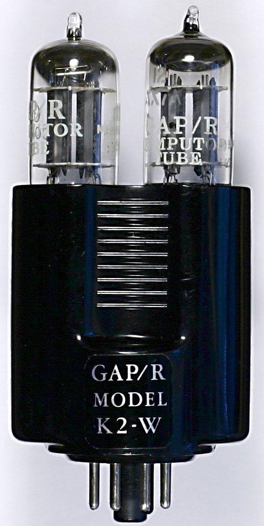
5 Op Amps Made originally for analogue computing Widely used for instrumentation, bespoke circuits, small amps, buffer circuits Cheap technology Readily available Robust Versatile
6 Op Amps Dual Power supply +15V and -15V Zin 2Mohms (note: may change with resistive networks) Zout 75ohms Gain 200,000 Bandwidth 1MHz at unity gain realistically, 10 to 100kHz bandwidth forced down due to internal cct.


7 Op Amps Only few components needed to generate precise gain

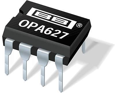
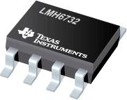
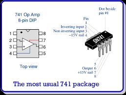
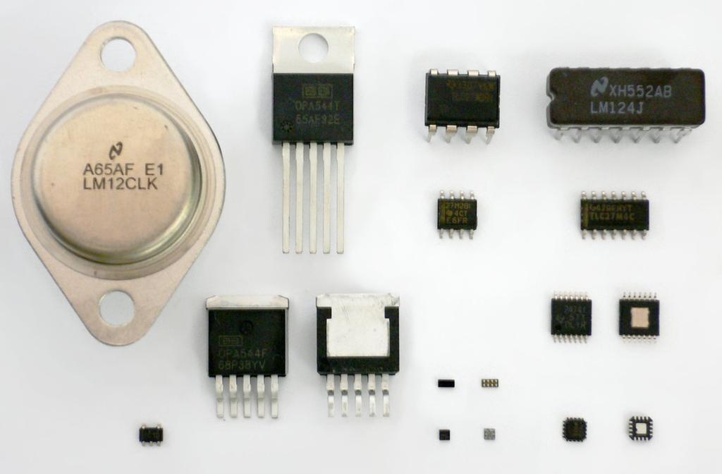
8 The Op Amp IC Typical numbers 741, 747, LM324, LM 339 Packages come in single, dual and quad op amps, in DIL 8 pins and 14 pins

9 How to kill an Op Amp
10
11
12
13 LM 339
14 LM358
15 Op Amp Golden Rules 1. The output tries to do whatever is necessary to make the voltage difference between the two inputs zero 2. The two inputs do not draw any current


16 OP Amp Circuit
17 OP Amp Packaging


18

19
20
21 OP Amp Inverting Amplifier
22 Inverting Amplifier Note: that the output voltage is inverted i.e. positive Voltage is applied at the input a negative Voltage will be seen at the output
23 Task Inverting Amplifiers Having a box of 10k resistors and 741 op amps design an amplifier having a gain of 10 Design a circuit which can be used as a buffer.
24 OP Amp Non Inverting Amplifier
25 Task Non Inverting Amplifier Having a box of 10k resistors and 741 op amps design an amplifier having a gain of 9 How could you design a non-inverting amplifier having a variable or tunable gain?

26 Task: You have got a box full of 10k resistors, hundreds of them. You have a dynamic microphone which you want to use for a PA system. Unfortunately the PA system has only got "Line" level input. Using diagram below work out what a typical line level input is:
27 A dynamic microphone has a typical input level of 1.5 millivolts RMS. Work out: - peak voltage for a typical dynamic microphone - how much gain do you need to generate to achieve 0dBu Ref level (pro)? - Which Op-Amp design would you choose Non-Inverting or Inverting, what will be the difference - What will be the significance if the input impedance is low? - Design an Op Amp to reach line level voltages - How would you use your 10k resistors to get the desired values - Series or Parallel connections - using Multisims verify your findings - with line level input impedance of 10k, would you require a voltage follower? Discuss?
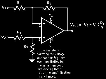
28 Differential Amplifier
29
30 Differential Amplifier Formula Note: R1 = Rf = R2 = Rg will not generate any gain but only amplify the difference. Using a different ratio for R1 and Rf or R2 and Rg will introduce a gain factor in the output
31 Differential Amplifiers Tasks: 1. Calculate the output using the formula above: V1 = 5V V2 = 2V All resistors have a value of 10k 2. Calculate the output: Using the same voltages as above but with different resistors R1 = 10k R2 = 10k Rg = 20k Rf = 20k What do you find?
32 Voltage Follower (unity gain amplifier or unity buffer amplifier) Realistic value for Z is about 1 Mohm to 1 Tohm. The circuit is used to minimise impact on the source where Vin comes from and to provide higher current at Vout without impacting the source circuit. Nevertheless the circuit may become unstable when connected to a capacitive load. A solution may be to use two inverting amplifiers configuration with R1 and Rf of equal value.
33 What does this circuit do?

34 The Summing Amplifier

35

36 How does the circuit work? Think about the Op Amp rules
37
38 The Inverting Integrator What does the circuit do?
39 The Inverting Integrator Remember: Capacitors like a.c. but hate DC An ac signal can easily pass through a capacitor Remember that the higher the frequency the lower the reactance Xc measured in ohms. The circuit works as a low pass filter! It allows low Hz to go through freely and higher frequencies are cut out hence the term Top Cut Filter.

40 Fun with OP Amps
41 The Inverting Integrator A pointer: RC is the time constant, it will give the time it takes for a signal to reach it's peak. 95% of the peak is achieved after three time constants.
42
43

44 Line following cct. Using Op Amps
Operational Amplifiers
 Fundamentals of op-amp Operation modes Golden rules of op-amp Op-amp circuits Inverting & non-inverting amplifier Unity follower, integrator & differentiator Introduction An operational amplifier, or op-amp,
EE 3305 Lab I Revised July 18, 2003
 Operational Amplifiers Operational amplifiers are high-gain amplifiers with a similar general description typified by the most famous example, the LM741. The LM741 is used for many amplifier varieties
Lesson number one. Operational Amplifier Basics
 What About Lesson number one Operational Amplifier Basics As well as resistors and capacitors, Operational Amplifiers, or Op-amps as they are more commonly called, are one of the basic building blocks
ECEN Network Analysis Section 3. Laboratory Manual
 ECEN 3714----Network Analysis Section 3 Laboratory Manual LAB 07: Active Low Pass Filter Oklahoma State University School of Electrical and Computer Engineering. Section 3 Laboratory manual - 1 - Spring
Analog Electronics. Lecture Pearson Education. Upper Saddle River, NJ, All rights reserved.
 Analog Electronics V Lecture 5 V Operational Amplifers Op-amp is an electronic device that amplify the difference of voltage at its two inputs. V V 8 1 DIP 8 1 DIP 20 SMT 1 8 1 SMT Operational Amplifers
Chapter 9: Operational Amplifiers
 Chapter 9: Operational Amplifiers The Operational Amplifier (or op-amp) is the ideal, simple amplifier. It is an integrated circuit (IC). An IC contains many discrete components (resistors, capacitors,
Experiments #7. Operational Amplifier part 1
 Experiments #7 Operational Amplifier part 1 1) Objectives: The objective of this lab is to study operational amplifier (op amp) and its applications. We will be simulating and building some basic op-amp
Community College of Allegheny County Unit 8 Page #1. Op-Amps
 Community College of Allegheny County Unit 8 Page #1 Op-s "You will say that I am always conjuring up awful difficulties & consequences my answer to this is it is an important part of the duty of an engineer"
EKT 314 ELECTRONIC INSTRUMENTATION
 EKT 314 ELECTRONIC INSTRUMENTATION Elektronik Instrumentasi Semester 2 2012/2013 Chapter 3 Analog Signal Conditioning Session 2 Mr. Fazrul Faiz Zakaria school of computer and communication engineering.
Chapter 2. Operational Amplifiers
 Chapter 2. Operational Amplifiers Tong In Oh 1 Objective Terminal characteristics of the ideal op amp How to analyze op amp circuits How to use op amps to design amplifiers How to design more sophisticated
Data Conversion and Lab Lab 1 Fall Operational Amplifiers
 Operational Amplifiers Lab Report Objectives Materials See separate report form located on the course webpage. This form should be completed during the performance of this lab. 1) To construct and operate
EE320L Electronics I. Laboratory. Laboratory Exercise #2. Basic Op-Amp Circuits. Angsuman Roy. Department of Electrical and Computer Engineering
 EE320L Electronics I Laboratory Laboratory Exercise #2 Basic Op-Amp Circuits By Angsuman Roy Department of Electrical and Computer Engineering University of Nevada, Las Vegas Objective: The purpose of
Università degli Studi di Roma Tor Vergata Dipartimento di Ingegneria Elettronica. Analogue Electronics. Paolo Colantonio A.A.
 Università degli Studi di Roma Tor Vergata Dipartimento di Ingegneria Elettronica Analogue Electronics Paolo Colantonio A.A. 2056 Operational amplifiers (op amps) Operational amplifiers (op amps) are among
Chapter 9: Operational Amplifiers
 Chapter 9: Operational Amplifiers The Operational Amplifier (or op-amp) is the ideal, simple amplifier. It is an integrated circuit (IC). An IC contains many discrete components (resistors, capacitors,
tyuiopasdfghjklzxcvbnmqwertyuiopas dfghjklzxcvbnmqwertyuiopasdfghjklzx cvbnmqwertyuiopasdfghjklzxcvbnmq
 qwertyuiopasdfghjklzxcvbnmqwertyui opasdfghjklzxcvbnmqwertyuiopasdfgh jklzxcvbnmqwertyuiopasdfghjklzxcvb nmqwertyuiopasdfghjklzxcvbnmqwer Instrumentation Device Components Semester 2 nd tyuiopasdfghjklzxcvbnmqwertyuiopas
MODEL ANSWER SUMMER 17 EXAMINATION Subject Title: Linear Integrated Circuit Subject Code:
 MODEL ANSWER SUMMER 17 EXAMINATION Subject Title: Linear Integrated Circuit Subject Code: Important Instructions to examiners: 1) The answers should be examined by key words and not as word-to-word as
Special-Purpose Operational Amplifier Circuits
 Special-Purpose Operational Amplifier Circuits Instrumentation Amplifier An instrumentation amplifier (IA) is a differential voltagegain device that amplifies the difference between the voltages existing
Lab: Operational Amplifiers
 Page 1 of 6 Laboratory Goals Familiarize students with Integrated Circuit (IC) construction on a breadboard Introduce the LM 741 Op-amp and its applications Design and construct an inverting amplifier
Operational Amplifiers
 Operational Amplifiers Here we see two matched differential amps cascaded to form a basic OPAMP. The differential pair cancel temperature drifts and common mode noise at the input. First built to perform
Homework Assignment 03
 Homework Assignment 03 Question 1 (Short Takes), 2 points each unless otherwise noted. 1. Two 0.68 μf capacitors are connected in series across a 10 khz sine wave signal source. The total capacitive reactance
Assignment 11. 1) Using the LM741 op-amp IC a circuit is designed as shown, then find the output waveform for an input of 5kHz
 Using the LM741 op-amp IC a circuit is designed as shown, then find the output waveform for an input of 5kHz") Assignment 11 1) Using the LM741 op-amp IC a circuit is designed as shown, then find the output waveform for an input of 5kHz Vo = 1 x R1Cf 0 Vin t dt, voltage output for the op amp integrator 0.1 m 1
Assignment 11 1) Using the LM741 op-amp IC a circuit is designed as shown, then find the output waveform for an input of 5kHz Vo = 1 x R1Cf 0 Vin t dt, voltage output for the op amp integrator 0.1 m 1
EK307 Active Filters and Steady State Frequency Response
 EK307 Active Filters and Steady State Frequency Response Laboratory Goal: To explore the properties of active signal-processing filters Learning Objectives: Active Filters, Op-Amp Filters, Bode plots Suggested
OPERATIONAL AMPLIFIERS (OP-AMPS) II
 II") OPERATIONAL AMPLIFIERS (OP-AMPS) II LAB 5 INTRO: INTRODUCTION TO INVERTING AMPLIFIERS AND OTHER OP-AMP CIRCUITS GOALS In this lab, you will characterize the gain and frequency dependence of inverting op-amp
OPERATIONAL AMPLIFIERS (OP-AMPS) II LAB 5 INTRO: INTRODUCTION TO INVERTING AMPLIFIERS AND OTHER OP-AMP CIRCUITS GOALS In this lab, you will characterize the gain and frequency dependence of inverting op-amp
CHARACTERIZATION OF OP-AMP
 EXPERIMENT 4 CHARACTERIZATION OF OP-AMP OBJECTIVES 1. To sketch and briefly explain an operational amplifier circuit symbol and identify all terminals. 2. To list the amplifier stages in a typical op-amp
Electronic Simulation Software for Teaching and Learning
 Electronic Simulation Software for Teaching and Learning Electronic Simulation Software: 1. Ohms Law (a) Example 1 Zoom 200% (i) Run the simulation to verify the calculations provided. (ii) Stop the simulation
Lab 9: Operational amplifiers II (version 1.5)
") Lab 9: Operational amplifiers II (version 1.5) WARNING: Use electrical test equipment with care! Always double-check connections before applying power. Look for short circuits, which can quickly destroy
Lab 9: Operational amplifiers II (version 1.5) WARNING: Use electrical test equipment with care! Always double-check connections before applying power. Look for short circuits, which can quickly destroy
Assist Lecturer: Marwa Maki. Active Filters
 Active Filters In past lecture we noticed that the main disadvantage of Passive Filters is that the amplitude of the output signals is less than that of the input signals, i.e., the gain is never greater
THIRD SEMESTER ELECTRONICS - II BASIC ELECTRICAL & ELECTRONICS LAB DEPARTMENT OF ELECTRICAL ENGINEERING
 THIRD SEMESTER ELECTRONICS - II BASIC ELECTRICAL & ELECTRONICS LAB DEPARTMENT OF ELECTRICAL ENGINEERING Prepared By: Checked By: Approved By: Engr. Saqib Riaz Engr. M.Nasim Khan Dr.Noman Jafri Lecturer
DEPARTMENT OF ELECTRICAL ENGINEERING LAB WORK EE301 ELECTRONIC CIRCUITS
 DEPARTMENT OF ELECTRICAL ENGINEERING LAB WORK EE301 ELECTRONIC CIRCUITS EXPERIMENT : 5 TITLE : ACTIVE FILTERS OUTCOME : Upon completion of this unit, the student should be able to: 1. gain experience with
AN-671 APPLICATION NOTE One Technology Way P.O. Box 9106 Norwood, MA Tel: 781/ Fax: 781/
 APPLICATION NOTE One Technology Way P.O. Box 910 Norwood, MA 0202-910 Tel: 781/329-4700 Fax: 781/32-8703 www.analog.com Reducing RFI Rectification Errors in In-Amp Circuits By Charles Kitchin, Lew Counts,
TRANSDUCER INTERFACE APPLICATIONS
 TRANSDUCER INTERFACE APPLICATIONS Instrumentation amplifiers have long been used as preamplifiers in transducer applications. High quality transducers typically provide a highly linear output, but at a
Learning Objectives:
 Learning Objectives: At the end of this topic you will be able to; recall the conditions for maximum voltage transfer between sub-systems; analyse a unity gain op-amp voltage follower, used in impedance
PHYS 536 The Golden Rules of Op Amps. Characteristics of an Ideal Op Amp
 PHYS 536 The Golden Rules of Op Amps Introduction The purpose of this experiment is to illustrate the golden rules of negative feedback for a variety of circuits. These concepts permit you to create and
UNIVERSITY OF NORTH CAROLINA AT CHARLOTTE Department of Electrical and Computer Engineering
 UNIVERSITY OF NORTH CAROLINA AT CHARLOTTE Department of Electrical and Computer Engineering EXPERIMENT 5 GAIN-BANDWIDTH PRODUCT AND SLEW RATE OBJECTIVES In this experiment the student will explore two
ELC224 Final Review (12/10/2009) Name:
 Name:") ELC224 Final Review (12/10/2009) Name: Select the correct answer to the problems 1 through 20. 1. A common-emitter amplifier that uses direct coupling is an example of a dc amplifier. 2. The frequency
ELC224 Final Review (12/10/2009) Name: Select the correct answer to the problems 1 through 20. 1. A common-emitter amplifier that uses direct coupling is an example of a dc amplifier. 2. The frequency
Op-Amp Simulation Part II
 Op-Amp Simulation Part II EE/CS 5720/6720 This assignment continues the simulation and characterization of a simple operational amplifier. Turn in a copy of this assignment with answers in the appropriate
EE431 Lab 1 Operational Amplifiers
 Feb. 10, 2015 Report all measured data and show all calculations Introduction The purpose of this laboratory exercise is for the student to gain experience with measuring and observing the effects of common
ENGR4300 Test 3A Fall 2002
 1. 555 Timer (20 points) Figure 1: 555 Timer Circuit For the 555 timer circuit in Figure 1, find the following values for R1 = 1K, R2 = 2K, C1 = 0.1uF. Show all work. a) (4 points) T1: b) (4 points) T2:
Homework Assignment 10
 Homework Assignment 10 Question The amplifier below has infinite input resistance, zero output resistance and an openloop gain. If, find the value of the feedback factor as well as so that the closed-loop
Introduction to Op Amps
 Introduction to Op Amps ENGI 242 ELEC 222 Basic Op-Amp The op-amp is a differential amplifier with a very high open loop gain 25k AVOL 500k (much higher for FET inputs) high input impedance 500kΩ ZIN 10MΩ
Linear IC s and applications
 Questions and Solutions PART-A Unit-1 INTRODUCTION TO OP-AMPS 1. Explain data acquisition system Jan13 DATA ACQUISITION SYSYTEM BLOCK DIAGRAM: Input stage Intermediate stage Level shifting stage Output
Emitter Coupled Differential Amplifier
 Emitter Coupled Differential Amplifier Returning to the transistor, a very common and useful circuit is the differential amplifier. It's basic circuit is: Vcc Q1 Q2 Re Vee To see how this circuit works,
1) Consider the circuit shown in figure below. Compute the output waveform for an input of 5kHz
 Consider the circuit shown in figure below. Compute the output waveform for an input of 5kHz") ) Consider the circuit shown in figure below. Compute the output waveform for an input of 5kHz Solution: a) Input is of constant amplitude of 2 V from 0 to 0. ms and 2 V from 0. ms to 0.2 ms. The output
) Consider the circuit shown in figure below. Compute the output waveform for an input of 5kHz Solution: a) Input is of constant amplitude of 2 V from 0 to 0. ms and 2 V from 0. ms to 0.2 ms. The output
Department of Mechanical Engineering
 Department of Mechanical Engineering 2.010 CONTROL SYSTEMS PRINCIPLES Introduction to the Operational Amplifier The integrated-circuit operational-amplifier is the fundamental building block for many electronic
ELEC207 LINEAR INTEGRATED CIRCUITS
 Concept of VIRTUAL SHORT For feedback amplifiers constructed with op-amps, the two op-amp terminals will always be approximately equal (V + = V - ) This condition in op-amp feedback amplifiers is known
CHARACTERISTICS OF OPERATIONAL AMPLIFIERS - II
 CHARACTERISTICS OF OPERATIONAL AMPLIFIERS - II OBJECTIVE The purpose of the experiment is to examine non-ideal characteristics of an operational amplifier. The characteristics that are investigated include
Lab 8: SWITCHED CAPACITOR CIRCUITS
 ANALOG & TELECOMMUNICATION ELECTRONICS LABORATORY EXERCISE 8 Lab 8: SWITCHED CAPACITOR CIRCUITS Goal The goals of this experiment are: - Verify the operation of basic switched capacitor cells, - Measure
Microprocessor based process control
 Microprocessor based process control Presented by Dr. Walid Ghoneim Lecture on: Op Amps and Their Applications in Signal Conditioning References: Op Amps for Everyone, MANCINI, R. (2002). The Forrest Mims
ELECTRONICS. EE 42/100 Lecture 8: Op-Amps. Rev B 3/3/2010 (9:13 PM) Prof. Ali M. Niknejad
 Prof. Ali M. Niknejad") A. M. Niknejad University of California, Berkeley EE 100 / 42 Lecture 8 p. 1/21 EE 42/100 Lecture 8: Op-Amps ELECTRONICS Rev B 3/3/2010 (9:13 PM) Prof. Ali M. Niknejad University of California, Berkeley
A. M. Niknejad University of California, Berkeley EE 100 / 42 Lecture 8 p. 1/21 EE 42/100 Lecture 8: Op-Amps ELECTRONICS Rev B 3/3/2010 (9:13 PM) Prof. Ali M. Niknejad University of California, Berkeley
ELECTRONICS. EE 42/100 Lecture 8: Op-Amps. Rev A 2/10/2010 (6:47 PM) Prof. Ali M. Niknejad
 Prof. Ali M. Niknejad") A. M. Niknejad University of California, Berkeley EE 100 / 42 Lecture 8 p. 1/21 EE 42/100 Lecture 8: Op-Amps ELECTRONICS Rev A 2/10/2010 (6:47 PM) Prof. Ali M. Niknejad University of California, Berkeley
A. M. Niknejad University of California, Berkeley EE 100 / 42 Lecture 8 p. 1/21 EE 42/100 Lecture 8: Op-Amps ELECTRONICS Rev A 2/10/2010 (6:47 PM) Prof. Ali M. Niknejad University of California, Berkeley
Electronic Devices. Floyd. Chapter 6. Ninth Edition. Electronic Devices, 9th edition Thomas L. Floyd
 Electronic Devices Ninth Edition Floyd Chapter 6 Agenda BJT AC Analysis Linear Amplifier AC Load Line Transistor AC Model Common Emitter Amplifier Common Collector Amplifier Common Base Amplifier Special
EE LINEAR INTEGRATED CIRCUITS & APPLICATIONS
 UNITII CHARACTERISTICS OF OPAMP 1. What is an opamp? List its functions. The opamp is a multi terminal device, which internally is quite complex. It is a direct coupled high gain amplifier consisting of
Infrared Communications Lab
 Infrared Communications Lab This lab assignment assumes that the student knows about: Ohm s Law oltage, Current and Resistance Operational Amplifiers (See Appendix I) The first part of the lab is to develop
What is an Op-Amp? The Surface
 What is an Op-Amp? The Surface An Operational Amplifier (Op-Amp) is an integrated circuit that uses external voltage to amplify the input through a very high gain. We recognize an Op-Amp as a massproduced
4.2.2 Metal Oxide Semiconductor Field Effect Transistor (MOSFET)
") 4.2.2 Metal Oxide Semiconductor Field Effect Transistor (MOSFET) The Metal Oxide Semitonductor Field Effect Transistor (MOSFET) has two modes of operation, the depletion mode, and the enhancement mode.
4.2.2 Metal Oxide Semiconductor Field Effect Transistor (MOSFET) The Metal Oxide Semitonductor Field Effect Transistor (MOSFET) has two modes of operation, the depletion mode, and the enhancement mode.
UNIT I. Operational Amplifiers
 UNIT I Operational Amplifiers Operational Amplifier: The operational amplifier is a direct-coupled high gain amplifier. It is a versatile multi-terminal device that can be used to amplify dc as well as
Low Pass Filter Introduction
 Low Pass Filter Introduction Basically, an electrical filter is a circuit that can be designed to modify, reshape or reject all unwanted frequencies of an electrical signal and accept or pass only those
PURPOSE: NOTE: Be sure to record ALL results in your laboratory notebook.
 EE4902 Lab 9 CMOS OP-AMP PURPOSE: The purpose of this lab is to measure the closed-loop performance of an op-amp designed from individual MOSFETs. This op-amp, shown in Fig. 9-1, combines all of the major
Physics 303 Fall Module 4: The Operational Amplifier
 Module 4: The Operational Amplifier Operational Amplifiers: General Introduction In the laboratory, analog signals (that is to say continuously variable, not discrete signals) often require amplification.
Concepts to be Reviewed
 Introductory Medical Device Prototyping Analog Circuits Part 3 Operational Amplifiers, http://saliterman.umn.edu/ Department of Biomedical Engineering, University of Minnesota Concepts to be Reviewed Operational
An electronic unit that behaves like a voltagecontrolled
 1 An electronic unit that behaves like a voltagecontrolled voltage source. An active circuit element that amplifies, sums, subtracts, multiply, divide, differentiate or integrates a signal 2 A typical
Third Year (Electrical & Telecommunication Engineering)
") Z PRACTICAL WORK BOOK For The Course EE-315 Electric Filter For Third Year (Electrical & Telecommunication Engineering) Name of Student: Class: Batch : Discipline: Class Roll No.: Examination Seat No.
Z PRACTICAL WORK BOOK For The Course EE-315 Electric Filter For Third Year (Electrical & Telecommunication Engineering) Name of Student: Class: Batch : Discipline: Class Roll No.: Examination Seat No.
Intruder Alarm Name Mohamed Alsubaie MMU ID Supervisor Pr. Nicholas Bowring Subject Electronic Engineering Unit code 64ET3516
 Intruder Alarm Name MMU ID Supervisor Subject Unit code Course Mohamed Alsubaie 09562211 Pr. Nicholas Bowring Electronic Engineering 64ET3516 BEng (Hons) Computer and Communication Engineering 1. Introduction
DEPARTMENT OF ELECTRICAL ENGINEERING AND COMPUTER SCIENCE MASSACHUSETTS INSTITUTE OF TECHNOLOGY CAMBRIDGE, MASSACHUSETTS 02139
 DEPARTMENT OF ELECTRICAL ENGINEERING AND COMPUTER SCIENCE MASSACHUSETTS INSTITUTE OF TECHNOLOGY CAMBRIDGE, MASSACHUSETTS 019.101 Introductory Analog Electronics Laboratory Laboratory No. READING ASSIGNMENT
Chapter 4: AC Circuits and Passive Filters
 Chapter 4: AC Circuits and Passive Filters Learning Objectives: At the end of this topic you will be able to: use V-t, I-t and P-t graphs for resistive loads describe the relationship between rms and peak
Sensor Interfacing and Operational Amplifiers Lab 3
 Name Lab Day Lab Time Sensor Interfacing and Operational Amplifiers Lab 3 Introduction: In this lab you will design and build a circuit that will convert the temperature indicated by a thermistor s resistance
Operational Amplifier BME 360 Lecture Notes Ying Sun
 Operational Amplifier BME 360 Lecture Notes Ying Sun Characteristics of Op-Amp An operational amplifier (op-amp) is an analog integrated circuit that consists of several stages of transistor amplification
Lecture 11. Operational Amplifier (opamp)
") Lecture 11 Operational Amplifier (opamp) Peter Cheung Department of Electrical & Electronic Engineering Imperial College London URL: www.ee.ic.ac.uk/pcheung/teaching/de1_ee/ E-mail: p.cheung@imperial.ac.uk
Lecture 11 Operational Amplifier (opamp) Peter Cheung Department of Electrical & Electronic Engineering Imperial College London URL: www.ee.ic.ac.uk/pcheung/teaching/de1_ee/ E-mail: p.cheung@imperial.ac.uk
Operational Amplifiers
 Operational Amplifiers for Basic Electronics http://cktse.eie.polyu.edu.hk/eie209 by Prof. Michael Tse January 2005 Where do we begin? We begin with assuming that the op-amp is an ideal element satisfying
Single Supply, Rail to Rail Low Power FET-Input Op Amp AD820
 a FEATURES True Single Supply Operation Output Swings Rail-to-Rail Input Voltage Range Extends Below Ground Single Supply Capability from + V to + V Dual Supply Capability from. V to 8 V Excellent Load
Chapter 2. Operational Amplifiers
 Chapter 2. Operational Amplifiers Tong In Oh 1 2.3 The Noninverting Configuration v I is applied directly to the positive input terminal of the op amp One terminal of is connected to ground Closed-loop
EET 438a Automatic Control Systems Technology Laboratory 1 Analog Sensor Signal Conditioning
 EET 438a Automatic Control Systems Technology Laboratory 1 Analog Sensor Signal Conditioning Objectives: Use analog OP AMP circuits to scale the output of a sensor to signal levels commonly found in practical
CHADALAWADA RAMANAMMA ENGINEERING COLLEGE (AUTONOMOUS) Chadalawada Nagar, Renigunta Road, Tirupati
 Chadalawada Nagar, Renigunta Road, Tirupati") IC APPLICATIONS LABORATORY MANUAL Subject Code : 15A04507 Regulations : R15 Class : V Semester (ECE) CHADALAWADA RAMANAMMA ENGINEERING COLLEGE (AUTONOMOUS) Chadalawada Nagar, Renigunta Road, Tirupati 517
IC APPLICATIONS LABORATORY MANUAL Subject Code : 15A04507 Regulations : R15 Class : V Semester (ECE) CHADALAWADA RAMANAMMA ENGINEERING COLLEGE (AUTONOMOUS) Chadalawada Nagar, Renigunta Road, Tirupati 517
School of Sciences. ELECTRONICS II ECE212A 2 nd Assignment
 School of Sciences SPRING SEMESTER 2010 INSTRUCTOR: Dr Konstantinos Katzis COURSE / SECTION: ECE212N COURSE TITLE: Electronics II OFFICE RM#: 124 (1 st floor) OFFICE TEL#: 22713296 OFFICE HOURS: Monday
Lecture Week 5. Quiz #2 Ohm s Law Homework Power Review Shorthand Notation Active Components Ideal Op-amps
 Lecture Week 5 Quiz #2 Ohm s Law Homework Power Review Shorthand Notation Active Components Ideal Op-amps Quiz 2 Ohm s Law (20 pts.) Please clear desks and turn off phones and put them in back packs You
Basics of Analog Multiplexers 1. Exercises TI Precision Labs Op Amps
 Basics of Analog Multiplexers 1 Exercises TI Precision Labs Op Amps 1 VSS VDD 1. In the circuit below, one of the input channels of the MUX36S08 is fed with a 2V p-p sinewave signal. The output of the
Lab 4 - Operational Amplifiers 1 Gain ReadMeFirst
 Lab 4 - Operational Amplifiers 1 Gain ReadMeFirst Lab Summary There are three basic configurations for operational amplifiers. If the amplifier is multiplying the amplitude of the signal, the multiplication
Operational Amplifiers
 Operational Amplifiers Spring 2008 Sean Lynch Lambros Samouris Tom Groshans History of Op Amps Non Named for their originally intended functions: performing mathematical operations and amplification Addition
DEPARTMENT OF ELECTRICAL ENGINEERING AND COMPUTER SCIENCE MASSACHUSETTS INSTITUTE OF TECHNOLOGY CAMBRIDGE, MASSACHUSETTS 02139
 DEPARTMENT OF ELECTRICAL ENGINEERING AND COMPUTER SCIENCE MASSACHUSETTS INSTITUTE OF TECHNOLOGY CAMBRIDGE, MASSACHUSETTS 019 Spring Term 00.101 Introductory Analog Electronics Laboratory Laboratory No.
When you have completed this exercise, you will be able to relate the gain and bandwidth of an op amp
 Op Amp Fundamentals When you have completed this exercise, you will be able to relate the gain and bandwidth of an op amp In general, the parameters are interactive. However, in this unit, circuit input
Chapter 14 Operational Amplifiers
 1. List the characteristics of ideal op amps. 2. Identify negative feedback in op-amp circuits. 3. Analyze ideal op-amp circuits that have negative feedback using the summing-point constraint. ELECTRICAL
Single Supply, Rail to Rail Low Power FET-Input Op Amp AD820
 a FEATURES True Single Supply Operation Output Swings Rail-to-Rail Input Voltage Range Extends Below Ground Single Supply Capability from V to V Dual Supply Capability from. V to 8 V Excellent Load Drive
L02 Operational Amplifiers Applications 1
 L02 Operational Amplifiers Applications 1 Chapter 9 Ideal Operational Amplifiers and Op-Amp Circuits Donald A. Neamen (2009). Microelectronics: Circuit Analysis and Design, 4th Edition, Mc-Graw-Hill Prepared
Unit WorkBook 1 Level 4 ENG U22 Electronic Circuits and Devices 2018 UniCourse Ltd. All Rights Reserved. Sample
 Pearson BTEC Level 4 Higher Nationals in Engineering (RQF) Unit 22: Electronic Circuits and Devices Unit Workbook 1 in a series of 4 for this unit Learning Outcome 1 Operational Amplifiers Page 1 of 23
ActiveLowPassFilter -- Overview
 ActiveLowPassFilter -- Overview OBJECTIVES: At the end of performing this experiment, learners would be able to: Describe the concept of active Low Pass Butterworth Filter Obtain the roll-off factor and
Operational Amplifiers
 CHAPTER 5 Operational Amplifiers Operational amplifiers (or Op Amp) is an active circuit element that can perform mathematical operations between signals (e.g., amplify, sum, subtract, multiply, divide,
C H A P T E R 02. Operational Amplifiers
 C H A P T E R 02 Operational Amplifiers The Op-amp Figure 2.1 Circuit symbol for the op amp. Figure 2.2 The op amp shown connected to dc power supplies. The Ideal Op-amp 1. Infinite input impedance 2.
Operational Amplifiers
 Operational Amplifiers Jim Emery 4/7/2011 Contents 1 Operational Amplifiers 1 11 The Inverting Amplifier 3 12 The Slew rate 5 13 The Noninverting Amplifier 5 14 The Voltage Follower 6 15 The Differentiating
Description. Output Stage. 5k (10k) - + 5k (10k)
 - + 5k (10k)") THAT Corporation Low Noise, High Performance Audio Preamplifier IC FEATURES Low Noise: 1 nv/hz input noise (60dB gain) 34 nv/hz input noise (0dB gain) (1512) Low THD+N (full audio bandwidth): 0.001% 40dB
THAT Corporation Low Noise, High Performance Audio Preamplifier IC FEATURES Low Noise: 1 nv/hz input noise (60dB gain) 34 nv/hz input noise (0dB gain) (1512) Low THD+N (full audio bandwidth): 0.001% 40dB
When input, output and feedback voltages are all symmetric bipolar signals with respect to ground, no biasing is required.
 1 When input, output and feedback voltages are all symmetric bipolar signals with respect to ground, no biasing is required. More frequently, one of the items in this slide will be the case and biasing
Instrumentation amplifier
 Instrumentationamplifieris a closed-loop gainblock that has a differential input and an output that is single-ended with respect to a reference terminal. Application: are intended to be used whenever acquisition
CENG4480 Embedded System Development and Applications The Chinese University of Hong Kong Laboratory 1: Op Amp (I)
") CENG4480 Embedded System Development and Applications The Chinese University of Hong Kong Laboratory 1: Op Amp (I) Student ID: 2018 Fall 1 Introduction This lab session introduces some very basic concepts
CENG4480 Embedded System Development and Applications The Chinese University of Hong Kong Laboratory 1: Op Amp (I) Student ID: 2018 Fall 1 Introduction This lab session introduces some very basic concepts
Engineering Department More Analog Secrets Your Subject Mother Never Told You
 Engineering Department More Analog Secrets Your Subject Mother Never Told You Name Address THAT Corporation 127 th AES Convention New York, Oct 2009 2 Agenda Focus on Mic Preamps THAT1570 new analog mic
Differential Amplifiers
 Differential Amplifiers Benefits of Differential Signal Processing The Benefits Become Apparent when Trying to get the Most Speed and/or Resolution out of a Design Avoid Grounding/Return Noise Problems
Chapter 10: Operational Amplifiers
 Chapter 10: Operational Amplifiers Differential Amplifier Differential amplifier has two identical transistors with two inputs and two outputs. 2 Differential Amplifier Differential amplifier has two identical
Lecture 4. Integrated Electronics
 Lecture 4 Integrated Electronics P, N is the doping of silicon to carry P (+) or N (-) charge) DIODES -> Recitifier I P N If V > V ON of diode, V V ON I = R Forward bias, conducting I Von ~ 0.6 V Example:
Model 176 and 178 DC Amplifiers
 Model 176 and 178 DC mplifiers Features*! Drifts to 100 MΩ! CMR: 120 db @! Gain Linearity of ±.005% *The key features of this amplifier series, listed above, do not necessarily apply
Mechatronics. Analog and Digital Electronics: Studio Exercises 1 & 2
 Mechatronics Analog and Digital Electronics: Studio Exercises 1 & 2 There is an electronics revolution taking place in the industrialized world. Electronics pervades all activities. Perhaps the most important
Designing Microphone Preamplifiers. Steve Green 24th AES UK Conference June 2011
 Designing Microphone Preamplifiers Steve Green 24th AES UK Conference June 2011 This presentation is an abbreviated version of a tutorial given at the 2010 AES Conference in San Francisco. The complete
ADA485-/ADA485- TABLE OF CONTENTS Features... Applications... Pin Configurations... General Description... Revision History... Specifications... 3 Spe
 NC NC NC NC 5 6 7 8 6 NC 4 PD 3 PD FEATURES Ultralow power-down current: 5 na/amplifier maximum Low quiescent current:.4 ma/amplifier High speed 75 MHz, 3 db bandwidth V/μs slew rate 85 ns settling time