Contents. Ⅰ. General. Ⅱ. Open-package Inspection. Ⅲ. Safety Note. Warning:
|
|
|
- Gwenda Wheeler
- 6 years ago
- Views:
Transcription
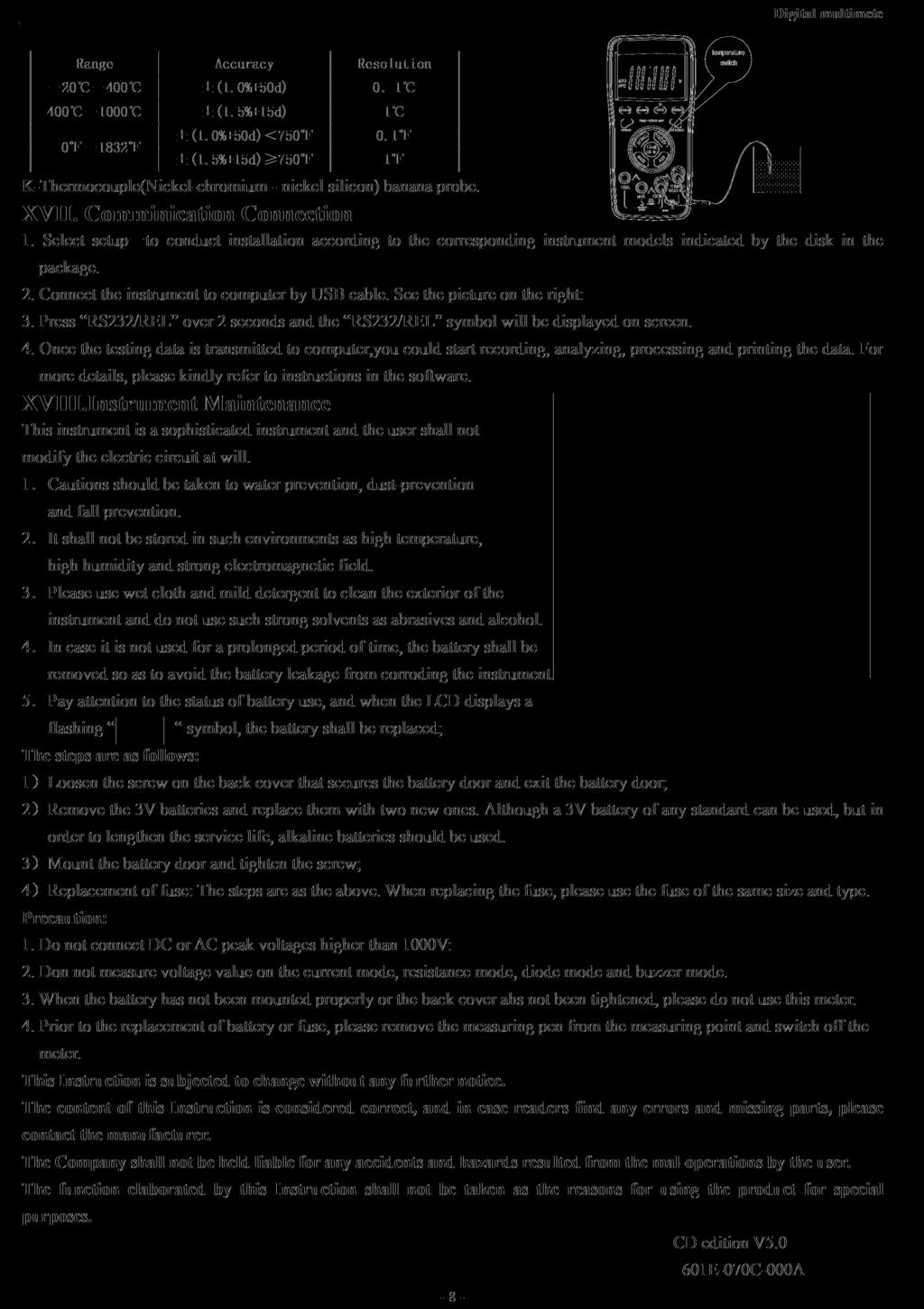
1 ontents 1. General 1 2. Open-package Inspection Safety Note Description of Safety Symbols Description of Instrument Panel and Pushbutton unctions 2 6. Other unctions Property D Voltage (DV) A Voltage (AV) D urrent (DA) A urrent (AA) Resistance Diode and On-and-Off Test apacitance () requency () Temperature Measurement ommunication onnection Instrument Maintenance.. 8 Ⅰ. General Endowed with the key touching function instead of the traditional mechanical knobs, is a new type of 3 5/6 digital multimeter equipped with the LD display device with the text height of 33mm which has the merits of visual display, easy operation, stable performance and high reliability. It can be used to measure D voltage, A voltage, D current, A current, resistance, capacitance, frequency, temperature, diode and make on-and-off test. Meanwhile, it is available for unit symbol display, data retention, the measurement of maximum and minimum value, automatic/manual range ing, automatic power off and alarm function. The complete machine takes a ing integrated circuit which can directly drive LD microprocessor and double-integrating A/D and a digital display drive offering high resolution and high precision. Due to it's complete functions, high measurement accuracy and convenient operation, the multimeter is the ideal tool in laboratory and factory as well as for radio fans and family. Ⅱ. Open-package Inspection Open the package box and take out the meter, check carefully if the following accessories are absent or damaged. If there is any absence or damage, please contact the distributor immediately. Digital Multimeter 1 P Instruction Manual 1 copy Test Leads 1 pair Temperature Probe (K-Thermocouple) 1 P P Interface able 1 P Software Disk 1 P 1.5V batteries ("AAA" 7# batteries) 2 Ps Holster 1 P Ⅲ. Safety Note In accordance with IE1010 clause (the safety standard issued by International Electrotechnical ommission), IT is designed and produced according to the safety requirements of pollution level Ⅱ. Warning: In order to avoid endangering the operator s safety, prior to the operation of the instrument, please read the instruction - 1 -
2 manual carefully, and conform to the safety warning information and operation instruction strictly to use the instrument. 1. When voltage above 30V, current above 10mA, A power line with inductive load or power line during electric fluctuation is measured, please beware of electric shock. 2. Prior to measurement, check if the measurement function is in conformity with the LD display, and if the pushbutton is at the trigger position. heck if the meter pen is contacted reliably, connected correctly, and grounded well and etc. in order to avoid electric shock. 3. Only if the meter is used with the matched meter pen, can it meet the requirement of safety standard. When the line of the meter pen is damaged, it is necessary to replace another one of the same model or the same electrical specification. 4. Don t use other unconfirmed or disapproved protector tube to replace the protector tube inside the meter. Only the protector tube of the same model or same specification can be replaced. Before the replacement, the meter pen must leave the measuring point and ensure there is no any signal at the input terminal. 5. Don t use other unconfirmed or disapproved battery to replace the battery inside the meter. Only the battery of the same model or same electrical specification can be replaced. Before the replacement, the meter pen must leave the measuring point and ensure there is no any signal at the input terminal. 6. When the electrical measurement is made, never let your body get in touch with the ground directly, and don t touch uncovered metal terminal, output port, lead clamp and etc. where earth potential may exist. Dry clothes, rubber shoes, rubber cushion and other insulating material are usually used to keep your body insulated against the ground. 7. Don t store and use it in the high-temperature, high-humidity, inflammable and strong magnetic field environment. 8. It may do damage to the meter and endanger the operator s safety if the voltage value beyond the permitted ultimate voltage value is measured. The ultimate voltage value permitted for measurement is marked on the instrument panel, and never measure the value exceeding the standard. Don t input the ultimate value out of regulation in order to avoid electric shock and the damage to the meter. 9. When the meter pen is inserted into the current socket, don t measure any voltage for fear that the meter should be damaged and the operator s safety be endangered. 10. Don t try calibrating or repairing the meter. When it is indeed necessary for that, only the qualified professional personnel who have had special training or gained approval can make it. 11. During measurement, the requirement of measurement function must be in accordance with LD display. Please be sure to disconnect the line of the meter pen with the measured object first and ensure there is no any input signal. It is forbidden to the function/range selection during measurement 12. When is shown on LD display, please replace battery immediately to ensure the measurement precision. 13. It is not allowed to insert the meter pen into the current terminal to measure voltage! 14. Please don t change the circuits of the meter freely for fear that the meter be damaged and the safety be endangered. Ⅳ. Description of Safety Symbols Warning! High Voltage! Danger! Ground Double Insulation Battery Undervoltage A/D In accordance with the instructions of European Trade Union use Ⅴ. Description of Instrument Panel and Pushbutton unctions 1. Instrument model. 2. LD display area. 3. unction button: Used to select various measurement functions. 3-1 Hold backlight and reading-keeping. If the is pressed over 2 seconds, the backlight turns on. urther press the over 2 seconds, the backlight turns off or automatically turns off after 10 seconds. Pressing the - 2 -
3 - 3 - within 2 seconds could lock or unlock the data retention. Press the once to lock and press it again to unlock. 3-2 /DUTY: Press the key in the gear of frequency can between the frequency and the Duty ycle.press the key in the gear of A Voltage or A urren can among the voltage, current, frequency and duty cycle. 3-3 MAX/MIN: The maximum value and minimum value.press the function button and enter MAX mode, in which the maximum value is held; press the button again to enter MIN mode, in which the minimum value is held. After the MAX/MIN mode is entered, the display device indicates the MAX/MIN value. No analog bar display and auto power off function in this working environment.press down MAX/MIN button for 2 seconds, and then exit from MAX or MIN test. 3-4 Range: Automatic/Manual Range Switch. Pre-set it to automatic range when the device starts up, then it to manual range. In the mode of manual range, press the RANGE button once, it will skip to the previous shift. When it goes to the highest shift, it goes back to the lowest shift when the button is pressed again. The procedure repeats again in the same order. Press the button over 2 seconds, it will exit from manual range and enter the state of automatic range measurement. 3-5 REL: Relative Value Measurement. Press this key to show the relative value measurement, press again to cancel the relative value measurement. The procedure repeats in the same order. Press this key over 2 seconds, it will to RS232, which can be showed on the LD screen and the RS232 data transmission is thus open. urther press the key over 2 seconds, the RS232 icon diappears on the LD screen. Now the RS232 data transmission terminates. The procedure repeats. 4. POWER is the power. 5. unction Selection Button. 6. Input Port: Measure the positive input terminal of voltage, frequency, resistance, capacitance, diode as well as on-and-off test, and insert red meter pen A current input jack: Measure the positive input terminal of 10A shift A/D current, and insert red meter pen. 8. ma input port: Measure the positive input terminal of A/D. 9. OM input port: Measure the negative input terminal, and insert black meter pen. Ⅵ. Other unctions 1. Automatic power off After the meter is stopped for 15 minutes, it will cut off power automatically (power off), and then enter the dormant (power off) state. The built-in buzzer will send out warning tone in one minute before it powers off. If you want to restart power(power on), please press the power. If you want to cancel antomatic power-off, please press REL key over 2 seconds until the RS232 symbol appears. Meanwhile the APO symbol will be also turned off. Ⅶ. Property 1. General features 1-1 Display mode: LD 1-2. Maximum display: /6 display automatic polarity display and unit display Analog bar. 30 times/sec, display of 61 analog bars Measurement mode: dual integration A/D conversion Sampling rate: About 3 time/s Over range: Display OL 1-7. Low voltage display: about 2.4v, the symbol 1-8. Working temperature: :0~40 displayed
4 1-9 Storage temperature: -10~50, relative humidity <80% Power: Two 1.5v batteries ("AAA" 7# batteries) 1-11 Volume (Dimensions): 185mm 91mm 49mm(Length*width *height) 1-12 Weight: About 410g (including battery ) 2. Technical features Accuracy: ±(a% reading + d digits), the ambient temperature for ensuring accuracy: 23±5, relative humidity <75% The warranty period of calibration is one year from ex-factory date. Ⅷ. D Voltage (DV) 1.Press "A/D", select automatic measurement of D voltge., and respectively plug in the red and black meter pens into the terminals of VΩ and OM, as shown in the following diagram. 2.The initial state of the meter is the D voltage automatic measurement mode, which shows the symbols of D AUTO APO. Press RANGE is to select manual range mode; Press MAX/MIN once to show the Max measurement value. Press MAX/MIN again to show the Min measurement value. Press MAX/MIN over 2 seconds is to cancel the measurement of the MAX/MIN value. 3.Touch the measuring point with the meter measuring pen and connect it in parallel to the circuit being tested, and the polarity of the red meter pen wire and the tested voltage value are spontaneously displayed on the display. aution: a)voltages over D1000V or A750V cannot be tested. b) When measuring high voltages, special precautions must be taken to avoid electrical shock.when measurement is completed, immediately disconnect the meter pen and the measured circuit. c) In case OL is displayed for manual range mode, it indicated the range has been exceeded and it is necessary to select higher range mode to complete this measurement. 600mV 0.1mV 6V 1mV ±(0.5%+4d) 60V 10mV 600V 100mV 1000V ±(1.0%+4d) 1V Input impedance: 600mV range>60mω,the others are 10MΩ. Overload protection: 1000VD or 750V alternative peak. IX. A Voltage (AV) 1.ircularly press the A/D key until it selects the A Voltage automatic measurement mode. Meanwhile, the symbol A, AUTO, APO will appear on the LD. Respectively plug in the red and black meter pens into the terminals of " " and "com". See the picture below. 2.The initial state of the meter is automatic range, which shows "AUTO" symbol. Press the "Range" key and it to manual range mode. In the A mode of automatic/manual range, the frequency/ duty cycle can be measured by pressing /DUTY. However, the frequency response now is low, which is suitable for the measurement of high voltage and low frequency in the environment of magnetic field interference such as 220V/50-400, 380V/ aution: Voltages over D1000V or A750V cannot be tested. In case OL is displayed for manual range mode, it indicated the range has been exceeded and it is necessary to select higher range mode to complete this measurement. 6V 60V ±(0.8%+10d) 1mV 10mV voltage voltage
5 600V 100mV 750V ±(1.0%+6d) 1V Input impedance: 10MΩ. Overload protection:1000vd or 750V alternating peak. Display:Mean value response(calibrated with sine wave). requency response:(40-400). requency response: Duty ycle Display: (0.1%-99.9%) Duty ycle Display: (0.1%-99.9%). X. D urrent (DA) 1. Press the button or button. Plug the black meter pen into the terminal of OM and the red meter pen nto the terminal of ma or 10A. See the picture below. 2. ircularly press the button or button. Select automatic D 600aA and 10A current to test. The D AUTO APO symbols will appear on the LD screen. 3.In case OL is displayed on the display, it indicates the current being measured has exceed the current range, and please select higher ranges for measurements. aution: a)at the 10A mode, current bigger than 10A cannot be measured, and at ma mode, the current bigger than 600 ma cannot be measured. Otherwise this will lead to the burning of the fuse or damage the instrument. b) When the meter pen is plugged in the input terminal of the current, it is strictly prohibited to have the meter pen connected in parallel on any circuits. 60mA 600mA 6A 10A ±(1.0%+10d) ±(1.2%+10d) The maximum input current: 10A (not exceeding 15s)) 10μA 100μA 1mA 10mA Overload protection: 0.6A/250V fuse; 10A/250V fuse. XI. A urrent (AA) 1. Press the button or button. Plug the black meter pen into the hole of OM and the red meter pen into the hole of ma or 10A. See the picture below. 2. ircularly press the button or button. Select automatic A 600aA and 10A current to test. The A AUTO APO symbols will appear on the LD screen. 3. In case OL is displayed on the display, it indicates the current being measured has exceed the current range, and please select higher ranges for measurements. aution: a)at the 10A mode, current bigger than 10A cannot be measured, and at ma mode, the current bigger than 600 ma cannot be measured. Otherwise this will lead to the burning of the fuse or damage the instrument. b) When the meter penis plugged in the input terminal of the current, it is strictly prohibited to have the meter pen connected in parallel on any circuits. 60mA 600mA 6A 10A ±(1.5%+10d) ±(2.5%+15d) The maximum input current: 10A (not exceeding 15s)) Overload protection: 0.6A/250V fuse; 10A/250V fuse. 10μA 100μA 1mA 10mA 10A 400mA D/ D/
6 XII. Resistance 1. Press button, and respectively plug the red and black meter pens into the holes of 2.ircularly press and OM. button and select resistance measurement. Meanwhile, a corresponding symbol will appear on the LD screen. In automatic resistance measurement mode, you could select manual measurement by pressing "Range". aution: a) When measuring the capacity, all the powers within the tested circuits must be disconnected and the capacitance shall be sufficiently discharged. b) When measuring the resistance, any occurrence of voltage may Lead to inaccurate readings, and if the 250V protection voltage is exceeded, it may damage the meter or threaten the safety of the user. c) When the range of 600Ω is in use, first sort-circuit the meter pens and measure the resistance of the lead wires and then deduct it in the actual measurement. 600Ω ±(0.8%+5d) 0.1Ω 6kΩ 60kΩ 600kΩ 6MΩ ±(0.8%+4d) 1Ω 10Ω 100Ω 1kΩ 60MΩ ±(1.2%+10d) 10kΩ Open circuit voltage: 600mV. Overload protection: 250V D or A peak values. XIII. Diode and On-and-Off Test 1. Press button and respectively plug the red and black pens into and OM. 2. ircularly press button to select the diode or buzzer measurement. In Diode mode, LD screen displays " " and voltage symbol, and the buzzer symbol " " is also displayed on the screen. 3. onnect the red meter pen to the positive of the diode, the black meter pen to the negative of the diode. aution: a) In case the diode is open circuit or the polarities are connected reversely, OL will be displayed on the screen. b) When checking the diode, all the powers within the tested circuits must be disconnected and the capacitance shall be sufficiently discharged. c) When the measurement is completed, immediately disconnect the meter and the measured circuit. Range Display value Measurement condition orward D current Diode forward is about 1.0mA, and voltage drop backward voltage is about 3.0V. If Buzzer emits a long sound and the resistance of the two points is measured as 30Ω Open circuit voltage is about 1.2V Overload protection: 250V D or A peak value. XIV. apacity () 1. Press " " button and respectively plug in the red and black meter pens into and OM. diode 2. ircularly press " " button and select the automatic measurement range of capacity. Meanwhile, the corresponding symbol will appear on the LD screen. No manual measurement range and analog bar will be displayed in apacity mode. D/ 10A D/ buzzer
7 aution: a) When measuring the capacity, all the powers within the tested circuits must be disconnected and the capacitance shall be sufficiently discharged b)when measuring big capacitors, it takes a longer time, about 100u per 15 seconds. c) When the measurement is completed, immediately disconnect the meter and the measured circuit. 40n ±(5.0%+30d) 10p 400n 4μ 40μ ±(3.5%+8d) 100p 1n 10n 200μ ±(5.0%+10d) 100n Overload protection: 250V D or A peak value. XV. requency () 1. Press " " button to conduct frequency measurement. Respectively plug in the meter pen into VΩ and OM. 2. Have the testing end of the meter pen connected in parallel with the signal sources to be measured and read the results from the display. (Note: No analog bar will displayed in this mode) 3. When testing frequency, press "/DUTY" once to conduct duty cycle measurement. Press "/DUTY" once more to enter the frequency status. 4. Read the current results from the display. aution: a) Do not input signals higher than 60V, otherwise it may damage the instrument and pose dangers to human safety. b) After all the measurements are completed, it is necessary to disconnect the meter pen and the tested circuit k 100k 1M 20M ±(0.3%+2d) Input sensitivity: 1.5V effective value k 10k Overload protection: 250VD or alternating peak XVI.Temperature Measurement 1. Press " " button over 2 seconds, select temperature mode for celsius measurement. Meanwhile, the temperature symbol will be displayed. urther press " same order. To exit from temperature measurement, press " ", it will be displayed as ahrenheit. The procedure repeats in the " button over 2 seconds. 2. Respectively plug the postive input end and negative insertion end of temperature probe into the terminals of " " and " OM". 3. Put the induction end of temperature probe on the surface of the tested object. See the picture on the right. 4. Read the current testing results from the display. aution: a) When the input end is open circuit, it indicates normal temperature. b) Do not change the temperature sensor at random, otherwise the accuracy of measurement can not be guaranteed. capacitance c) Do not input voltage in temprature mode, otherwise the meter may be damaged.

8
Contents. 1. General 1. Ⅱ. Open-package Inspection. Ⅲ. Safety Note. Warning:
 ontents www.abra-electronics.com DM-500 USB 1. General 1 2. Open-package Inspection. 1 3. Safety Note.... 1 4. Description of Safety Symbols. 2 5. Description of Instrument Panel and Pushbutton unctions
RAGU 81D DIGITAL MULTIMETER OPERATION MANUAL
 RAGU 81D DIGITAL MULTIMETER OPERATION MANUAL Contents I. General...- 1 - Ⅱ. Open-package Inspection...- 2 - III. Safety Considerations... - 3 - IV.Instrument Panel & Button Function Description...- 9 -
Thank you again for choosing AstroAI, if you have any questions or concerns regarding your product, please contact us at
 ASTROAI USER MANUAL DT132A 4000 Count Auto-Ranging Multimeter Thank you for purchasing the AstroAI DT132A 4000 Count Auto-Ranging Multimeter. It is a 3 ¾ digit, 3999 counts, auto-ranging digital multimeter.
VC835 DIGTAL MULTIMETER Operation Manual
 VC835 DIGTAL MULTIMETER Operation Manual CONTENTS GENERAL DESCRIPTION Safety Instructions FEATURES OPERATION MAINTENANCE TROUBLE SHOOTING 1. General Description This is a 3 1/2 digital multimeter with
ETHOS 5030 TRUE-RMS DIGITAL MULTIMETER OPERATION MANUAL
 ETHOS 5030 TRUE-RMS DIGITAL MULTIMETER OPERATION MANUAL 1 1. SAFETY INFORMATION SAFETY SYMBOLS Warning! Dangerous Voltage (Risk of electric shock). Caution! Refer to the user s manual before using this
DVM1190 DIGITAL MULTIMETER
 DIGITAL MULTIMETER 1. Introduction Thank you for buying the. This digital multimeter has a large LCD, a data-hold function and a backlight. The device uses a very practical safety mechanism that keeps
Model: &
 600A True RMS Digital Clamp Meter Model: 72-3097 & 72-3099 1 CONTENTS Page Number Details 3 Important Safety Information 4 Product overview 4 Key Functions 5 General Specification 5 Electrical Specification
OPERATOR S INSTRUCTION MANUAL
 OPERATOR S INSTRUCTION MANUAL AUTO-RANGE DUAL DISPLAY CONFORMED IEC1010 DIGITAL MULTIMETER CONTENTS PAGE SAFETY INFORMATION..... DESCRIPTION.. OPERATING INSTRUCTION.. SPECIFICATIONS.... ACCESSORIES. BATTERY
Analog Technologies VC99. Multimeter FEATURES
 FEATURES LCD Display Max Display: 6000(3 6/7) Digits Automatic Polarity, Unit Symbol and 61 Section Analog Display Measurement Method: Double Integral A/D Conversion Sampling Rate: Approx.3 times/sec Over-Range
Digital Multimeter, Pen Type
 MODEL: D03127 Digital Multimeter, Pen Type 1 CONTENTS Page Number Description 3 Important Safety Information 3 Electrical Symbols 4 Overview 4 Measurement Operation 5 AC & DC Voltage Measurement 5 AC &
MS2109A AC/DC Clamp Meter. User Manual. Contents
 MS2109A AC/DC Clamp Meter User Manual Contents 1. Safety information 1 1.1 Preparation 1 1.2 Usage 1 1.3 Signs and Labels 2 1.4 Maintenance 2 2. Description 2 2.1 Part name 3 2.2 Switch and button description
Model ST Instruction Manual. True RMS Autoranging Digital Multimeter. reedinstruments. www. com
 Model ST-9933 True RMS Autoranging Digital Multimeter Instruction Manual reedinstruments com Table of Contents Safety... 3 Features... 4 Specifications...4-8 Technical...4-5 Accuracy...5-8 Display Description...
EM420A/420B DIGITAL MULTIMETER OWNERS MANUAL Read this owners manual thoroughly before use
 http://www.all-sun.com EM420A/420B DIGITAL MULTIMETER OWNERS MANUAL V Read this owners manual thoroughly before use WARRANTY This instrument is warranted to be free from defects in material and workmanship
770E DIGITAL MULTIMETER OPERATOR S MANUAL
 770E DIGITAL MULTIMETER OPERATOR S MANUAL TABLE OF CONTENTS 1.Overview... 1 2.Panel Layout...1/2 3. Safety information... 2 4. Specical cautions for operation.... 2 5.General specifications...2/3 6.Testing
MS8211 DIGITAL MULTIMETER INSTRUCTION MANUAL
 MS8211 DIGITAL MULTIMETER INSTRUCTION MANUAL Ω CONTENTS CONTENTS 1. SAFETY INFORM...1 4.4 Range Transform...10 1.1 Preliminary...1 4.5 Auto Power Off...10 1.2 During use...2 4.6 Preparation For Measurement...11
OWNER S MANUAL HH0308C. AUTO-RANGING DC/True RMS AC DIGITAL MULTIMETER
 OWNER S MANUAL HH0308C AUTO-RANGING DC/True RMS AC DIGITAL MULTIMETER IMPORTANT! Read and understand this manual before using the tester. Failure to understand and comply with safety rules and operating
DIGITAL DUAL DISPLAY AC/DC CLAMP METER MODEL-860A OPERATION MANUAL
 DIGITAL DUAL DISPLAY AC/DC CLAMP METER MODEL-860A OPERATION MANUAL DIGITAL DUAL DISPLAY AC/DC CLAMP METER MODEL-860A TABLE OF CONTENTS TITLE PAGE Safety Information Safety Symbols... 1 Meter Description...
DIGITAL MULTIMETER OPERATING INSTRUCTIONS MODEL CDM-35. Part No
 DIGITAL MULTIMETER MODEL CDM-35 Part No.4500055 OPERATING INSTRUCTIONS 0304 The Meter may be hung on a wall, or supported as shown, depending upon which support is used. The probes may be located as shown,
MS8250A/B OPERATION MANUAL MS8250A. Hz% FUNC REL RANGE REL HOLD OFF 10A. Hz% A NCV. Hz% COM. A ma 10A FUSED 600V CAT IV.
 MS8250A/B DIGITAL MULTIMETER OPERATION MANUAL AUTO DC AC REL hfe PCLINK % C F kmωkz nµmfav MS8250A DIGITAL MULTIMETER Auto Power Off RANGE REL HOLD FUNC NCV A ma OFF 10A A ma 10A FUSED 600V CAT IV COM
AC/DC DIGITAL CLAMP METER OPERATION MANUAL
 AC/DC DIGITAL CLAMP METER OPERATION MANUAL HYS005661 A0 ACCESSORIES 6. ACCESSORIES 1) Test Leads: Electric Ratings 1000V 10A 1 pair (set) 2) Operating Manual 1 copy 3) 1.5V AAA Battery 3 piece - - 55 -
CONTENTS MS2033A. 1.Introduction Safety Information...01
 MS2033A AC Digital Clamp Meter User s Manual CAT III 600 V CONTENTS 1.Introduction...01 2.Safety Information...01 2.1 Precautions...02 2.2 Safety Symbols...03 3. Description...04 3.1 Front Panel...04 3.2
DIGITAL MULTIMETER AX-588B
 DIGITAL MULTIMETER AX-588B OPERATION MANUAL 1. Sumary His series product is a stable and battery-driven 3 ½ digital multimeter with high reliability. It adopts LCD screen with character height of 28mm;
DIGITAL MULTIMETER INSTRUCTION MANUAL
 DIGITAL MULTIMETER INSTRUCTION MANUAL 1 CONTENTS CONTENTS 1. SAFETY INFORMATION 1 1.1 PRELIMINARY 1 1.2 DURING USE 2 1.3 SYMBOLS 3 1.4 MAINTENANCE 4 2. DESCRIPTION 5 2.1 NAMES OF COMPONENTS 5 2.2 SWITCH,
Multifunction Digital
 MS2009A Multifunction Digital Clamp Meter User Manual 200/600 OFF 2/20 NCV SEL MAX V RAN HOLD OFF MS2009A AC CLAMP METER AUTO MAX C F kmω μmva CONTENTS Safety requirements...1 Safety signs...1 Notes...1
PEN TYPE DIGITAL MULTIMETER OPERATION MANUAL T8211D
 PEN TYPE DIGITAL MULTIMETER OPERATION MANUAL T8211D T8211D 1 1. SAFETY INFORMATION BE EXTREMELY CAREFUL IN THE USE OF THIS METER. Improper use of this device can result in electric shock or destroy of
AC/DC CLAMP METER USER S MANUAL
 AC/DC CLAMP METER USER S MANUAL CONTENTS PAGE SAFETY INFORMATION SYMBOL EXPLANATION SAFETY PRECAUTIONS 1 1 2 MAINTENANCE 3 GENERAL DESCRIPTION 4 PANEL DESCRIPTION 4 OPERATING INSTRUCTIONS... 7 SPECIFICATIONS
MM V 10A ENGLISH. INSTRUCTION MANUAL Auto-Ranging DATA HOLD AUDIBLE CONTINUITY MIN / MAX TEMPERATURE DIODE TEST CAPACITANCE
 INSTRUCTION MANUAL Auto-Ranging Digital Multimeter MM400 DATA HOLD AUDIBLE CONTINUITY MIN / MAX TEMPERATURE DIODE TEST CAPACITANCE 600V 10A 40MΩ 2 GENERAL SPECIFICATIONS Klein Tools MM400 is an auto-ranging
NOTE: Fully read and understand this manual before using this Digital Multimeter.
 ASTROAI USER MANUAL AUTO RANGING DIGITAL CLAMP METER Thank you for purchasing the Auto Ranging Digital Clamp Meter from AstroAI. The AstroAI Auto Ranging Digital Clamp Meter is designed to be safely and
DM-45 Digital Multimeter
 INSTRUCTION MANUAL DM-45 Digital Multimeter Read and understand all of the instructions and safety information in this manual before operating or servicing this tool. Description The Greenlee DM-45 Digital
IDEAL INDUSTRIES, INC. TECHNICAL MANUAL MODEL: MODEL: Multimeter Service Information
 IDEAL INDUSTRIES, INC. TECHNICAL MANUAL MODEL: 61-340 MODEL: 61-342 Multimeter Service Information The Service Information provides the following information: Precautions and safety information Specifications
DIGITAL MULTIMETER CONTENTS DIGITAL MULTIMETER CONTENTS
 CONTENTS CONTENTS CONTENTS 1. SAFETY INFORMATION...1 1.1 Preliminary...1 1.2 Dos and don ts...2 1.3 Symbols...3 1.4 Precautions...4 2. DESCRIPTION...5 2.1 Names of parts...6 2.2 Switches, buttons and input
MS2030 CAT III 600 V A V AUTO RS232
 MS2030 AC Digital Clamp Meter User s Manual CAT III 600 V AUTO RS232 A V CONTENTS 1.Introduction...1 2.Safety Information...1 2.1 Precautions...1 2.2 Safety Symbols...3 3. Description...4 3.1 Front Panel...4
User Manual Digital Clamp Multimeter. model no.: MSR-C600
 User Manual Digital Clamp Multimeter model no.: MSR-C600 Overview This Operating Manual covers information on safety and cautions. Please read the relevant information carefully and observe all the Warnings
DVM645BI BENCH MULTIMETER TAFELMULTIMETER MULTIMETRE DE TABLE BANCO MULTÍMETRO TISCHMULTIMETER. User Manual. Gebruikershandleiding
 BENCH MULTIMETER TAFELMULTIMETER MULTIMETRE DE TABLE BANCO MULTÍMETRO TISCHMULTIMETER User Manual Gebruikershandleiding Manuel d'utilisation Gebrauchsanleitung Introduction BENCH MULTIMETER This manual
OPERATOR S INSTRUCTION MANUAL DIGITAL MULTIMETER
 OPERATOR S INSTRUCTION MANUAL DIGITAL MULTIMETER SAFETY INFORMATION This multimeter has been designed according to IEC 1010 concerning electronic measuring instruments with an overvoltage category (CATⅡ)
DVM98. True RMS Digital Multimeter. 1 Safety information. 1.1 Preliminary. 1.2 During use
 True RMS Digital Multimeter DVM98 1 Safety information This multimeter has been designed according to IEC - 1010 concerning electronic measuring instruments with an overvoltage category (CAT II) and pollution
USER'S MANUAL DMR-6700
 USER'S MANUAL Multimeter True RMS DMR-6700 CIRCUIT-TEST ELECTRONICS www.circuittest.com Introduction This meter measures AC/DC Voltage, AC/DC Current, Resistance, Capacitance, Frequency (electrical & electronic),
S-11 S-11. Digital Multimeter Operating Instruction. Digital Multimeter Operating Instruction
 S-11 Digital Multimeter Operating Instruction S-11 Digital Multimeter Operating Instruction I. General introduction Welcome to use this product! This product is one kind of 3 6/7 portable multipurpose
OPERATING INSTRUCTION
 OPERATING INSTRUCTION AUTOMOTIVE MULTIMETER MODEL QM1444 the finger guards on the probes. Measuring voltage which exceeds the limits of the multimeter may damage the meter and expose the operator to a
AMM-1022 Digital Multimeter USER`S MANUAL
 Digital Multimeter USER`S MANUAL www.tmatlantic.com CONTENTS 1. SAFETY INFORMATION.3 2. DESCRIPTION..6 3. SPECIFICATIONS.8 4. OPERATING INSTRUCTION..11 4.1 Voltage measurement...11 4.2 Current measurement
Dawson DDM190. Digital Multimeter User s Manual
 Dawson DDM190 Digital Multimeter User s Manual TABLE OF CONTENTS LIMITED WARRANTY AND LIMITATION OF LIABILITY... 3 Out of the Box... 3 Accessories.. Error! Bookmark not defined. Safety Information... 7
Digital Clamp Meter. User Manual
 Digital Clamp Meter User Manual CM240 WWW.OWON.COM.CN Mar. 2016 edition V1.2 Copyright LILLIPUT Company. All rights reserved. The LILLIPUT's products are under the protection of the patent rights, including
Not for Reproduction
 1 ADVANCE PRODUCT SERVICE INFORMATION SUBJECT: OPERATING PROCEDURES FOR EXTECH DIGITAL MULTIMETER No: #66 DATE: 05/31/2010 MODELS: 19602 DIGITAL MULTIMETER A digital multimeter is necessary for electrical
Model DIGITAL MULTIMETER
 Model 57070 DIGITAL MULTIMETER INSTRUCTION MANUAL SAFETY INFORMATION To ensure safe operation, and in order to exploit to the full the functionality of the meter, please follow the directions in this section
AX-C Introduction. 2. Safety Information
 AX-C708 1. Introduction Read Safety Information before using the meter. ProcessMeter ( referred to as the meter )is a handheld, battery-operated tool for measuring electrical parameters. It has all the
True RMS Digital Multimeter Model:
 True RMS Digital Multimeter Model: 72-7780 1 SAFETY INFORMATION Please read these instructions carefully before use and retain for future reference. This meter is designed to meet IEC61010-1, 61010-2-032,
MS8268 HANDHELD DIGITAL MULTIMETER OPERATOR S INSTRUCTION MANUAL
 MS8268 HANDHELD DIGITAL MULTIMETER OPERATOR S INSTRUCTION MANUAL Table of Contents TITLE PAGE 1. GENERAL INSTRUCTIONS 1 1.1 Precaution safety measures 1 1.1.1 Preliminary 1 1.1.2 During use 2 1.1.3 Symbols
ProfiScale MULTI Multimeter
 1,5 V 9V 200 mv 600 V 200 ma 1/10 A ProfiScale MULTI Multimeter en Operating instructions BURG-WÄCHTER KG Altenhofer Weg 15 58300 Wetter Germany Introduction Want the reassurance of knowing whether current
MM700. True RMS ENGLISH. INSTRUCTION MANUAL Auto-Ranging. Measurement Technology
 INSTRUCTION MANUAL Auto-Ranging Digital Multimeter er True RMS Measurement Technology MM700 DATA & RANGE HOLD LOW IMPEDANCE AUDIBLE CONTINUITY MIN / MAX / RELATIVE TEMPERATURE DIODE TEST CAPACITANCE &
400Amp True RMS AC/DC Clamp Meter Model EX613
 User's Guide 400Amp True RMS AC/DC Clamp Meter Model EX613 Introduction Congratulations on your purchase of this Extech EX613 True RMS Clamp Meter. This meter measures AC Current, DC Current, AC/DC Voltage,
MODEL: D03128 CLAMP METER
 MODEL: D03128 CLAMP METER 1 CONTENTS Page Number Details 3 Important Safety Information 3 Features 4 Product Overview 5 Switches, Buttons & Input Jacks 5 LCD 6 Specifications 6 Electrical Specifications
Dawson DDM230C. True RMS Multimeter with Bar Graph Display User s Manual
 Dawson DDM230C True RMS Multimeter with Bar Graph Display User s Manual Table of Contents LIMITED WARRANTY AND LIMITATION OF LIABILITY... 3 Out of the Box... 3 Accessories... 4 Safety Information... 4
MS8223A. CAT.IIi 600 V
 Pen-type Digital Multimeter Manual MS8223A CAT.IIi 600 V CONTENTS 1. Safety Information......1 1.1 Preparing for use...1 1.2 During Use......2 1.3 Safety Symbols...3 1.4 Maintenance...4 2. Description......4
MM700. INSTRUCTION MANUAL Auto-Ranging Digital Multimeter True RMS
 INSTRUCTION MANUAL Auto-Ranging Digital Multimeter True RMS Measurement Technology MM700 DATA & RANGE HOLD LOW IMPEDANCE AUDIBLE CONTINUITY MIN / MAX / RELATIVE TEMPERATURE DIODE TEST CAPACITANCE & FREQUENCY
Digital Clamp Meter Model: &
 Digital Clamp Meter Model: 72-7224 & 72-7226 1 SAFETY INFORMATION Please read these instructions carefully before use and retain for future reference. This meter is designed to meet IEC61010-1, 61010-2-032,
Mini Clamp Meter Model:
 Mini Clamp Meter Model: 72-2985 1 CONTENTS Page Number Details 2 What s Included 3 Important Safety Information 3 Technical Specification 4 Product Overview 5 LCD Overview 6 Operation - AC/DC Voltage Measurement
MS6231 DIGITAL ENGINE ANALYZER OPERATOR S MANUAL CONTENTS CONTENTS
 CONTENTS MS6231 DIGITAL ENGINE ANALYZER OPERATOR S MANUAL CONTENTS 1. SAFETY INFORMATION 1 1.1 PRELIMINARY 2 1.2 DURING USE 3 1.3 SYMBOLS 5 1.4 MAINTENANCE 6 2. DESCRIPTION 8 2.1 NAMES OF COMPONENTS 9
DCM730. Digital Clamp Meter User s Manual
 DCM730 Digital Clamp Meter User s Manual Table of Contents LIMITED WARRANTY AND LIMITATION OF LIABILITY...1 Out of the Box...1 Safety Information...2 INTRODUCTION...4 Components and Buttons...6 Names of
Model : OPERATING MANUAL Table of Contents (1)
") Table of Contents (1) Title Overview Unpacking Inspection Safety Information Rules For Safe Operation International Electrical Symbols The Meter Structure Functional Buttons Measurement Operation A. DC
Table of Contents (1) Title Overview Unpacking Inspection Safety Information Rules For Safe Operation International Electrical Symbols The Meter Structure Functional Buttons Measurement Operation A. DC
MS8250D DUAL DISPLAY DIGITAL MULTIMETER User s Manual
 DUAL DISPLAY DIGITAL MULTIMETER User s Manual MS8250D 1. Safety Information Warning Use caution and follow all safety guidelines to prevent electric shock or damage to the meter. Please ready carefully
USER'S MANUAL DMR-4350
 USER'S MANUAL DIGITAL MULTIMETER DMR-4350 CIRCUIT-TEST ELECTRONICS www.circuittest.com TABLE OF CONTENTS SAFETY Safety Information...................................... 2 Safety Symbols........................................
1. SAFETY INFORMATION.1 2. DESCRIPTION SPECIFICATIONS.6 4. OPERATING INSTRUCTION Voltage measurement Current measurement 10
 CONTENTS 1. SAFETY INFORMATION.1 2. DESCRIPTION..4 3. SPECIFICATIONS.6 4. OPERATING INSTRUCTION..9 4.1 Voltage measurement...10 4.2 Current measurement 10 4.3 Resistance measurement...12 4.4 Diode test.12
Table of Contents Title Page
 Table of Contents Title Page Overview Unpacking Inspection Safety Information Rules For Safe Operation International Electrical Symbols The Meter Structure Rotary Switch Functional Buttons Display Symbols
CL900. True RMS 1000V 2000A 60MΩ ENGLISH. INSTRUCTION MANUAL 2000A Digital Clamp Meter. Measurement Technology
 ENGLISH INSTRUCTION MANUAL 2000A Digital Clamp Meter True RMS Measurement Technology NON-CONTACT VOLTAGE TESTING INRUSH CURRENT LOW IMPEDANCE DATA HOLD RANGE HOLD AUDIBLE CONTINUITY DIODE TEST CAPACITANCE
User Manual Digital Multimeter. model no.: MSR-U1000
 User Manual Digital Multimeter model no.: MSR-U1000 This Operating Manual covers information on safety and cautions. Please read the relevant information carefully and observe all the Warnings and Notes
Table of Content. The Statement Safety Statement Safety Instructions Safety Operation Specifications Safety Symbols...
 Table of Content The Statement... 1 Safety Statement... 1 Safety Instructions... 2 Safety Operation Specifications... 2 Safety Symbols... 4 Overview... 6 LCD Display... 6 Buttons... 8 Rotary Switch...
1. SAFETY 1.1. SAFETY INFORMATION 1.2. SAFETY SYMBOLS
 To all residents of the European Union Important environmental information about this product This symbol on the device or the package indicates that disposal of the device after its lifecycle could harm
User's Guide. 800 Amp AC/DC True RMS Clamp Meter. Model EX Washington Street Melrose, MA Phone Toll Free
 User's Guide 99 Washington Street Melrose, MA 02176 Phone 781-665-1400 Toll Free 1-800-517-8431 Visit us at www.testequipmentdepot.com 800 Amp AC/DC True RMS Clamp Meter Model EX730 Introduction Congratulations
Digital Multimeter with Backlight
 MODEL: D03126 Digital Multimeter with Backlight 1 CONTENTS Page Number Description 3 Important Safety Information 3 What s Included? 4 Overview 4 Front Panel Description 5 General Specification 5 DC Voltage
METRAVI. Table of Contents
 Table of Contents A. Your Meter s Feature B. Specifications C. Making Measurements D. Maintenance E. Accessories F. Using Holster G. Using Strap Introduction 540 is brand new Multimeter with 4 1/2 digits,
Digital Multimeter AX-572. Instruction manual
 Digital Multimeter AX-572 Instruction manual 1. SUMMARIZE The meter is a stable multimeter with 40mm LCD display, driven by battery. It's widely used on measuring DCV, ACV, DCA, ACA, resistance, capacitance,
User Manual Digital Multimeter
 User Manual Digital Multimeter model no.: MSR-R500 Questions or Concerns? support@etekcity.com visit etekcity.com for more products Safe and Proper Usage Thank you for purchasing the Etekcity MSR-R500
CD770 DIGITAL MULTIMETER INSTRUCTION MANUAL
 CD770 DIGITAL MULTIMETER INSTRUCTION MANUAL Table of Contents 1 SAFETY PRECAUTIONS Before use, read the following safety precautions.- 1-1 Explanation of Warning Symbols 001 1-2 Warning Messages for Safe
DC/AC CLAMP METER ISO-TECH 2000 USERS MANUAL
 DC/AC CLAMP METER ISO-TECH 2000 USERS MANUAL Warnings and Safety symbols: Caution, refer to this manual before using the meter. Dangerous voltages. Meter is protected throughout by double insulation or
Item ref: UK MTTR01 TRUE RMS DIGITAL MULTITESTER WITH USB INTERFACE. User Manual
 Item ref: 600.104UK MTTR01 TRUE RMS DIGITAL MULTITESTER WITH USB INTERFACE User Manual Please read this manual thoroughly and ensure all contents are fully understood before using the apparatus. WARNING
BENNING. Service Information MODEL: MM1-1 / MM1-2 / MM1-3
 BENNING MODEL: MM1-1 / MM1-2 / MM1-3 Service Information The Service Information provides the following information: Precautions and safety information Specifications Basic maintenance (cleaning, replacing
OPERATOR S INSTRUCTION MANUAL
 2 OPERATOR S INSTRUCTION MANUAL CLAMP METER HOLD 20 A 200 A 2 A 600 600 LIGHT ON/OFF Digital Clamp Meter 2 20 200 A khz COM CAT.II MAX 600 CONTENTS 1. General instruction.....1 2. Description...1 2.1 Precautions
KMD-S04 Multímetro de bolsillo
 www.grupotemper.com KMD-S04 Multímetro de bolsillo Table of Contents Title Page Overview ~~~~~~~~~~~~~~~~~~~~~~~~~~~~~~~~~~~~~~~~~~ 3 Unpacking Inspection ~~~~~~~~~~~~~~~~~~~~~~~~~~~~~~~~~ 4 Safety Information
DMM8900 SERIES USERS MANUAL
 DMM8900 SERIES USERS MANUAL WARRANTY This instrument is warranted to be free from defects in material and workmanship for a period of one year. Any instrument found defective within one year from the delivery
SAFETY PRECAUTIONS: Before use, read the following safety precautions
 [1] SAFETY PRECAUTIONS: Before use, read the following safety precautions This instruction manual explains how to use your multimeter CD731, CD751 safely. Before use, please read this manual thoroughly.
Dawson DDM181. Pocket-Size Autorange Digital Meter User s Manual
 Dawson DDM181 Pocket-Size Autorange Digital Meter User s Manual 1 Table of Contents LIMITED WARRANTY AND LIMITATION OF LIABILITY... 3 Out of the Box... 3 Accessories... 4 Important Safety Information...
USER MANUAL 600A AC Clamp Meter + NCV Model MA610
 USER MANUAL 600A AC Clamp Meter + NCV Model MA610 Additional User Manual Translations available at www.extech.com Introduction Thank you for selecting the Extech MA610 Clamp Meter. This meter measures
AC750 DIGITAL CLAMP METER
 AC750 DIGITAL CLAMP METER OWNER S MANUAL (English) Français, Español, Deutsch: www.cpsproducts.com CONTENTS 1. Safety Information 1.1 Preliminary...1 1.2 Usage...2 1.3 Symbols...3 1.4 General Use...4 2.
OPERATOR S INSTRUCTION MANUAL M-2625 AUTO RANGING DIGITAL MULTIMETER
 OPERATOR S INSTRUCTION MANUAL M-2625 AUTO RANGING DIGITAL MULTIMETER with Temperature Probe Copyright 2007 Elenco Electronics, Inc. Contents 1. Safety Information 3,4 2. Safety Symbols 5 3. Front Plate
UT207A/208A/209A Operating Manual. Table of Contents
 Table of Contents Title Overview Unpacking Inspection Safety Information Rules for Safe Operation International Electrical Symbols The Meter Structure Display Symbols Functional Buttons The Effectiveness
Pen-type DIGITAL MULTITESTER
 BST-MT267 Pen-type DIGITAL MULTITESTER INSTRUCTION MANUAL Index 1. Introduction... 2. Safety Notes... 3. Features... 4. Specifications... 5. General... 6. Instrument Layout... 7. Measurement... 8. Maintenance...
DIGITAL CLAMP METER Use s Manual
 MS2026 MS2026R DIGITAL CLAMP METER Use s Manual MS2026 FUNC. RANGE MAX/MIN Hz/% HOLD AC CLAMP METER Auto Range AUTO DC AC MAX MIN REL μnf %Hz kmω mva CAT III 600 V CONTENTS 1. Safety Information...1 1.1
USER'S MANUAL DMR-4300
 USER'S MANUAL DIGITAL MULTIMETER DMR-4300 CIRCUIT-TEST ELECTRONICS www.circuittest.com TABLE OF CONTENTS SAFETY Safety Information...................................... 2 Safety Symbols........................................
AUTO RANGING DIGITAL MULTIMETER
 AUTO RANGING DIGITAL MULTIMETER 12 MONTH WARRANTY LARGE DIGITAL DISPLAY AC/DC VOLTAGE & CURRENT MEASUREMENT CAT II SAFETY RATING CAT III TEST LEAD SAFETY RATING K8315 ED1 May 17 Table of Contents Know
Model UT201/202: OPERATING MANUAL. Table of Contents
 Table of Contents Title Overview Unpacking Inspection Safety Information Rules For Safe Operation International Electrical Symbols The Meter Structure Rotary Switch Functional Buttons The Effectiveness
User s Manual. MiniTec TM Series. Model MN26 (Model MN26T includes temperature probe) Mini Autoranging MultiMeter
 Mini Autoranging MultiMeter") User s Manual MiniTec TM Series Model MN26 (Model MN26T includes temperature probe) Mini Autoranging MultiMeter Introduction Congratulations on your purchase of Extech s MN26 Autoranging Multimeter. This
User s Manual MiniTec TM Series Model MN26 (Model MN26T includes temperature probe) Mini Autoranging MultiMeter Introduction Congratulations on your purchase of Extech s MN26 Autoranging Multimeter. This
M-1000D DIGITAL MULTIMETER
 OPERATOR S INSTRUCTION MANUAL DIGITAL MULTIMETER M-1000D Elenco Electronics, Inc. 150 Carpenter Avenue Wheeling, IL 60090 (847) 541-3800 Website: www.elenco.com e-mail: elenco@elenco.com Copyright 2008
4.5 Auto Power Off During use Preparation For Measurement Symbols...3
 MS8211 DIGITAL MULTIMETER INSTRUCTION MANUAL Ω CONTENTS CONTENTS 1. SAFETY INFORM...1 4.4 Range Transform...10 1.1 Preliminary...1 4.5 Auto Power Off...10 1.2 During use...2 4.6 Preparation For Measurement...11
MANUAL DE INSTRUÇÕES DO MULTÍMETRO DIGITAL MODELO MD-6456 Inglês
 MANUAL DE INSTRUÇÕES DO MULTÍMETRO DIGITAL MODELO MD-6456 Inglês Novembro 2016 Leia atentamente as instruções contidas neste manual antes de iniciar o uso do multímetro Table of Contents The Statement...
UT132 Series Manual. UT132 Series. Palm Size Digital Multimeter. Operating Manual -1-
 UT132 Series UT132 Series Manual Palm Size Digital Multimeter Operating Manual -1- Table of Contents 一 Overview 二 Unpacking Inspection 三 Safety Information 四 International Electrical Symbols 五 Overall
User s Guide. 400A AC/DC Clamp Meter. Model MA220
 User s Guide 400A AC/DC Clamp Meter Model MA220 Introduction Thank you for selecting the Extech MA200 AC/DC Clamp Meter. This meter measures AC/DC Current, AC/DC Voltage, Resistance, Capacitance, Frequency,
Compact Autoranging Clamp Meters. Models (400 A AC), (400 A AC/DC)
, (400 A AC/DC)") User Manual Compact Autoranging Clamp Meters with NIST-Traceable Calibration Models 20250-55 (400 A AC), 20250-56 (400 A AC/DC) THE STANDARD IN PRECISION MEASUREMENT 1065DGMAN_20250-55,-56 DS Clamp Meter
User Manual Compact Autoranging Clamp Meters with NIST-Traceable Calibration Models 20250-55 (400 A AC), 20250-56 (400 A AC/DC) THE STANDARD IN PRECISION MEASUREMENT 1065DGMAN_20250-55,-56 DS Clamp Meter
Instruction Manual ICM 3091N Digital AC Clampmeter EN FR IT DE ES
 Instruction Manual ICM 3091N Digital AC Clampmeter EN FR IT DE ES TABLE OF CONTENTS / EN TITLE TABLE OF CONTENTS PAGE 1. SAFETY INFORMATION... 1 2. TECHNICAL SPECIFICATIONS... 2 3. PARTS & CONTROLS...
3B SCIENTIFIC PHYSICS
 3B SCIENTIFIC PHYSICS Digital Multimeter E 1018832 Instruction sheet 12/16 SD/UD 1 probe 1a Finger guards 2 Measurement socket 10 A for current measurement in 10-A (positive) 3 Measurement socket COM (negative)
DL6508 User's Guide. 1500Amp True RMS AC/DC Clamp Meter
 DL6508 User's Guide 1500Amp True RMS AC/DC Clamp Meter Introduction Congratulations on your purchase of this DL6508 True RMS Clamp Meter. This meter measures AC Current, DC Current, AC/DC Voltage, Resistance,