Energy Measurement and Management MT830/MT831. Three-phase electronic multi-function meter for industry. Technical Description. Version 1.
|
|
|
- Aileen Stevenson
- 6 years ago
- Views:
Transcription


1 Energy Measurement and Management MT830/MT831 Three-phase electronic multi-function meter for industry! Technical Description Version 1.6
2 Table of contents: MT830/MT831 Three-phase electronic multi-function meter Meter characteristics Constituent parts Measuring system Microcomputer Real time clock LEDs Multi-tariff registration Maximum demand indicator Load Profile Registration of energy / power Display Keys Communication interfaces IR communication interface Meter reading in absence of measuring voltages (option) RS-485 interface RS-232 interface CS-communication interface Input /output module (MT831 meter only) Communication module (MT831 meter only) Fraud protection Detection of meter cover and terminal cover opening Handling with the meter Connection procedure Housing Terminal block Terminal block Current terminals Auxiliary voltage terminals: Sliding voltage bridge Dimensions Maintenance: Lifetime: Technical data Type designation Meter marking Input-output module marking (for MT831 meter only) Communication module marking (for MT831 meters only) Configuring a PC modem Appendix A: OBIS codes and data names Appendix B: Log book events Appendix C: Connection diagrams Energy Measurement and Management


3 MT830/MT831 Three-phase electronic multi-function meter MT830/MT831 three-phase electronic multi-function meter is intended for measuring active and apparent energy in two flow directions, reactive energy in four quadrants as well as imported and exported, maximal power of the above stated energies, registration of load curves and quality parameters of supplied electric energy in three-phase threeand four-wire networks. The meters can be connected directly, semi-directly or indirectly. They comply with the IEC , IEC , EN , IEC and IEC standards, VDEW demands, and they are manufactured in compliance with the ISO 9001 standard. The meter consists of a polycarbonate housing, electronics for measuring and processing measuring data, input/output as well as communication electronics. Two different meter versions are available: MT830 - a closed meter version with additional six terminals, which could be used for: o Communication interface o Functional or impulse inputs o Functional outputs o External power suplly Figure 1: MT830 a closed meter version MT831 a modular meter version with communication (MK) and input/output (MIO) module which could be subsequently built into the meter and six additional terminals Figure 2: MT831 a modular meter version 3
4 1. Meter characteristics Measuring active energy/power Measuring reactive energy/power in four quadrants and/or a sum of energies by individual quadrants (e.g. Q1+Q2 and Q3+Q4) Measuring apparent energy/power Calculating cumulative power Measuring and displaying parameters of energy quality: rms voltage values by phases Current by phases Harmonic components in voltage and current (up to the 8 th harmonic) Power factor per phase and total Phase angle between phase voltage and current Voltage failures Multi-tariff registration Load profiles (P.01, P.02) Log-books (P.98, P.99) Different display modes on LCD Meter reading in case of power down ( no power reading option with SONDA 6 (option) VDEW designed LCD presence of phase voltages, energy flow direction, units and 11 statuses Communications IR interface for a local readout and meter programming (IEC ) Auxiliary terminals The main meter board (MT830 & MT831) could be equipped with up to six auxiliary terminals, which could be: o Communication on board port (MT830 only) MT830 meter could be equipped with CS interface or RS-485 interface or RS-232 interface Communication with the meter is performed in compliance with the IEC standard, mode C. The meter operation is not affected during communication. Type of communication: Serial asynchronous half-duplex ISO start bit 7 data bits 1 bit parity - even 1 stop bit data transfer rate: 300, 600, 1200, 2400, 4800, 9600 Baud Each communication port supports fix baud rate (for use of transparent telephone modems) or communication protocol according to IEC standard (communication sequence is started with 300 baud). Communication parameters in the meter are programmable. The meter enables separate read out (different data) via IR and other communication interface at the same time. The MT831 meter could be equipped with different communication modules (MK). Two inputs (3 terminals) are used Functional or Impulse inputs 4
5 Control voltage is from 100 V.240 V AC/DC. Additional inputs & outputs could be implemented in input/output module (I/O module) the MT831 meter only. Electrical characteristics: OFF state <= 30 V ON state >= 45 V Internal resistance 190 KOhm Switch on delay typical 10 ms at 240V Four outputs in two functional groups (6 terminals) External power supply (2 terminals) Terminal Terminal designation V AC/DC V AC/DC Additional explanation External power supply External power supply Modular construction the MT831 meter only MT831 could be upgraded with input/output (MIO) and communication (MK) module. Fraud detection Detection of a meter cover and a terminal cover opening Connection to network: a three-phase meter can also be used as a single-phase or two-phase type Quality: High accuracy as well as time stability of measurement High reliability of operation and long life span (20 years) High immunity to EMC disturbances Simple and fast assembly A compact plastic housing is made of high quality self-extinguishable materials and is resistant to water and dust (IP53) Environment friendly: a meter is made of the materials that can be recycled or are not dangerous for the environment 2. Constituent parts The meter consists of the following units: Measuring systems Microcontroller with external memory Real time clock LCD Optical interface Keys LEDs Power supply : o Internal three phase switcher o external power supply o power supply via optical probe ( no power reading option with SONDA 6 ) 5


6 2.1. Measuring system Figure 3 A meter block diagram The measuring systems are based on Rogowski coils that measure changes on the induced voltage. Current flows through a current coil. Voltage is induced inside the air coils due to alternate magnetic field. There are two Rogowski coils on each phase. The measuring system is made of: 1. Current coil frame 2. Current coil 3. Two Rogowski coils 4. PCB Figure 4 Measuring system A measuring system measures induced voltage on measuring coils which is proportional to the current on input. The first coil measures load energy and the second one is a compensation coil which measures outside disturbances. Compensation value is subtracted from a measuring element. An output signal from Rogowsky coils is related to the input of the measuring integrated current. A signal is integrated, amplified and multiplied with measuring voltage and sent to the microprocessor. Figure 5 Measuring principle Sensors and circuits are protected from overvoltage. Influences of disturbance quantities are negligible, which assures high meter reliability. 6
7 2.2. Microcomputer A microcomputer enables: Meter functions by customer's specification Storing measuring data and parameters Storing measuring data for previous billing periods (factory settings is 15 billing periods) Demand calculations Load Profile function Compensating measuring protocol of voltage and current transformers Logbook Display control Certain supervision and control meter functions for measuring phase voltages Measuring phase voltages Measuring harmonic components in current and voltage Measuring frequency Operation of the microcomputer is controlled by a special Watch-dog circuit Real time clock A real time clock is controlled by a 32 khz quartz oscillator. The clock accuracy complies with the IEC standard requirements. Back up power supply source is built in the meter. It is usually a supercapactior and an Li battery which is directly soldered to the main printed circuit board. The supercapacitor assures energy for 250 hours of the clock operation in case of a complete power supply failure, while an Li battery assures 10 years of operation, with time life span of 20 years. A real time clock generates: A measuring period for power and a registration period for load profile Tariff programs, season changeover, transition to day light saving period and vice-versa Time stamps of individual events. A time-stamp consists of a date, an hour, a minute and a second of the event LEDs Two LEDs are built in the meter: Left active (imp/kwh) Right reactive (imp/kvarh) or apparent (imp/kvah) (programmable) They enable meter calibration. Impulse constants depend on nominal current and voltage and are programmable values. Factory settings: Direct connected meter o 3x230/400 V, 5(60) A imp/kwh o 3x230/400 V, 5(120) A 500 imp/kwh Transformer connected meter o 3x57.7/100. 3x240/415V, 5(6)A imp/kwh To reduce the control time a special factory test mode is built in the meter, which increases LED constants 10 times higher, in comparison with a normal operating mode. After power down/up event, all constants take the original factory settings. 3. Multi-tariff registration The meter enables registration of energy and power by separate tariff schemes. Up to 8 tariffs for energy and demand could be registered (factory settings 4 tariffs). The meter is equipped with 160 tariff registers. Time of switching individual tariff is defined by hour and minute with a resolution of 1 minute. A number of periods in a day where one or several tariffs can be valid is defined with configuration. The same is valid for different daily tariff programs. Up to 32 various types of a day (a day in a week and a holiday) can be defined. A number of seasons in a year (factory settings 4 seasons) is defined with configuration. Besides a current tariff program, the so-called slipping tariff programs can be defined. They are activated at previously defined dates. An optional number of holidays can be defined. A centuryold callendar is built in the meter. 7
8 4. Maximum demand indicator Maximum demand can be measured with a fixed or a sliding measuring period. A measuring period can be set from 1 minute to 60 minutes with a 1-minute resolution. It is possible to measure maximum demands for: Active energy in both flow directions Reactive energy in four quadrants as well as a sum of energies by individual quadrants (e.g. Q1+Q2 and Q3+Q4) Apparent energy in both energy-flow directions Maximum demands are registered by individual tariffs and cummulatively. Configuration of blocking the measurement of maximum demand for a certain time that follows a period of network voltage failure is also available. 5. Load Profile A programmable data recorder enabling registration of a load profile is built in the meter: Active, apparent power and energy (cumulative or absolute values) three-phase values in both energy flow directions Reactive power or energy (cumulative or absolute values) in four or combined quadrants (e.g. Q1+Q2 and Q3+Q4) Rms values of phase voltages Distortion factor Individual meter statuses (power supply failure, alarms) A registration period or a load profile can be set within the range from 1 to 60 minutes. Two load profiles (P.01 and P.02) could be implemented in the meter. The first one (P.01) is normaly used for registering energy or demand, and the second one for registering the last average of voltage, current and power factor. Last average registration is related to the measuring period. Load profile periods and measurment period are independend from each other. 6. Registration of energy / power The MT830/MT831 meter has three measuring systems and could be used in a three-phase three-wire or three-phase four-wire networks. Registration types: Vector registration ( Li), when the vector sum of energies is positive, the meter registers A+ energy; when the vector sum of energies is negative, the meter registers A- energy For example (phase load is the same) Phase: L1 L2 L3 Load: +A -A +A Total registration (1.8.0) (+A) + (-A) + (+A) = +A Total registration (2.8.0) 0 Meter registers +A (one phase load!!). Arithmetical registration the meter could register A+ and A- energy in the same time For example (phase load is the same) Phase: L1 L2 L3 Load: +A -A +A Total registration Positive direction (1.8.0) (+A) + (+A) = 2*(+A) Negative direction (2.8.0) -A If the second phase is wrongly connected, the meter also registers this energy with such registration type. Absolute active energy A For example (phase load is the same) 8
9 Phase: L1 L2 L3 Load: +A -A +A Total registration Positive direction (1.8.0) +A + -A + +A =3*(+A) With such registration the meter registers only imported energy, also in case of wrong connection. For measuring reactive energy a natural connection is used. Internal register provides for a corresponding voltage and current phase shift. MT830/MT831 meters could be provided with: three measuring systems (MT830 T1 /MT831 T1) transformer connected 7. Display LCD is designed according to the VDEW requirements. Figure 6 - LCD The measuring data on LCD are displayed with eight 7-segment 8 mm x 4 mm high numbers. Displayed data are identified with five-digit OBIS identification codes (IEC ), 6 mm x 3 mm high numbers. Dimension of LCD (visible area) is 69 mm x 20 mm. Meters have back-light illumination for easy data reading at metering place with bad light condition. The LCD is illuminated when any pushbutton is pressed. The illumination is switched-off after 3 minutes if no pushbutton was pressed at that time. A meter operates in different display modes Automatic data circulation Autoscrool (Time between two register presentations in LCD is programmable). Because only 5 digits are used for identification, 9 previous register values are presented on the LCD. Additional modes are accessible with a black and a red button. Displaying modes accessible with the black one: Manual data display registers Std data Manual data display network parameters (voltage, current, phase angle, etc.) Grid Manual data display Load Profile (P.01 and/or P.02 (programmable)) Presentation of the GSM modem parameters DiAg (C.C.3 signal level (should be higher than 17), C.C.4 GSM provider (1 home provider, 5 roaming), C.C.5 error code (should be 0)) Displaying modes accessible with the red button: Manual setting of time, date, etc. SET mode Registers presented in Autoscool mode with enhanced energy registers presentation TEST mode Resetting the LCD statuses of meter and terminal cover opening Intrusion restart mode Format and data units are programmed. At transformer connected meters, displayed measuring data can be primary, or secondary. Besides measuring data, the energy flow direction, presence of phase voltages, display of individual events, meter statuses and alarms can be displayed. 9
.")
10 7.1. Keys The meter is equipped with three keys. Black dislay key is used for transition from a basic to an extended data display mode. Red reset key is used for billing meter reset or, in combination with the DISPLAY key, for setting certain meter parameters (SET, TEST or Intrusion restart meter operation mode). The RESET key is sealed separately or it can be locked. Param key is under the meter cover and is used for setting meter parameters in the laboratory. 8. Communication interfaces An optical communication interface is located on the meter basic board. One of communication interfaces that are intended for remote meter readout (CS or RS-232 or RS-485) can be mounted on customer demand. The meter is provided with two independent communication channels IR communication interface The optical communication interface enables a user to set the meter parameters and read the measuring results (registers reading, a logbook, a load profile, reading individual registers, sending individual commands) Meter reading in absence of measuring voltages (option) On customer s request, the meter can be equipped with additional electronics, which enables communication via an optical interface also in case of measuring voltages failure. This is enabled with a special probe (SONDA 6). It is also possible to read meter data manually by means of the DISPLAY key. Figure 7 No power meter reading option with SONDA 6 (option for MT830/MT831) 8.2. RS-485 interface The RS-485 serial interface enables communication with maximum transmission rate 9600 bauds. The MT830 meters with a built-in RS 485 interface are equipped with two auxiliary terminals. Up to 31 meters can be connected to the RS-485 interface with maximum distance of 1200 m. In such configuration, the meter readout is obligatory with device 10

11 address! For longer distances (more than few hundred meters), the use of termination resistor of 120 Ohm on each edge is recommended. Terminal Terminal designation Additional explanation 27 A A terminal 29 B B terminal Table1 RS-485 terminals designation Figure 8 Meters connected to the modem via RS-485 interface 8.3. RS-232 interface The RS 232 serial interface enables communication with maximum transmission rate 9600 bauds. The MT830 meters with built-in RS 232 interface are equipped with three auxiliary terminals Terminal Terminal designation Additional explanation 27 RxD Rx terminal 28 GND Common terminal 29 TxD Tx terminal Table 2 RS-232 terminals designation or RJ11 connector. Figure 9 RS-232 RJ11 terminal designation 8.4. CS-communication interface The CS interface (20-mA current loop) complies with the DIN standard and is two-wire communication. It enables communication with maximum transmission rate 9600 bauds. The MT830 meters with built-in CS interface are equipped with two auxiliary terminals. Up to four meters can be connected to the CS interface with maximum distance of 1500m. In such configuration, the meter readout is obligatory with a device address! 11
 I/O modules are plug & play.")
12 Terminal Terminal designation Additional explanation 23 CS+ CS+ terminal 24 CS- CS- terminal Table 3 CS interface terminals designation Figure 10 Meters connected to the modem via CS interface. 9. Input /output module (MT831 meter only) I/O modules are plug & play. Two versions regarding the internal programming are available: Input output module function is predefined in module EEROM The module is pre-programmed in the factory. After inserting the module into the meter, the meter automatically accepts the module parameters (plug and play module). Terminals are marked according to the VDEW requirements. The module can be re- programmed only in the factory Input output module function is not predefined in module EEROM The function of input-output module terminals is defined when setting meter parameters which are specified in the group Input/output pins MeterView 4 program. Terminal designations: - Cx for common terminals - Tx for output terminals - TEx for input terminals where x is from 1 to n (a terminal number). Standard versions are: - MIO-V12L51 4 outputs + 1 output + 1 input - MIO-V42L81 4 outputs + 4 outputs + 4 inputs - MIO-V12L41B11 4 outputs + 1 output 5A bistable rele + 1 input Error on an input/output module does not influence in the meter operation. Figure 11 - Input/output module (MT831 only) 12
13 Definition of input terminals: Terminal Terminal designation 15 COM 13, 33 14, 34 TE1/2, TE3/4 ME1/2, ME3/4 16 MPE 17 MZE 18 MREa 19 MREb Additional explanation Common terminal for functional inputs Energy tariff input T1 T4 Demand tariff input M1 M4 External time/measurement period synchronization input External input for disabling of demand measurement Input a for external billing reset Input b for external billing reset 21 MKE1 Alarm input 1 22 MKE2 Alarm input 2 90 COM Common terminal for impulse inputs 91 IME1 Impulse input 1 92 IME2 Impulse input 2 Table 4 Input terminals designation Impulse inputs are realized as passive inputs. An impulse constant is programmable and could be different for each impulse input. Maximum impulse frequency is 25 imp/sec. Definition of output terminals: Terminal Terminal designation Additional explanation 35 COM Common terminal 36 MKA Alarm output 37 MPA Measurement output 38 ERA+A 39 ERA+R period Energy flow direction +A Energy flow direction +R 40 COM Common terminal 41 +AA Pulse output for +A 42 -AA Pulse output for -A 43 +RA Pulse output for +R 44 -RA Pulse output for -R 45 RA1 Pulse output for RA1 46 RA2 Pulse output for RA2 47 RA3 Pulse output for RA3 48 RA4 Pulse output for RA4 13

14 52 COM 54 COM 56 COM 58 COM 59 COM Common terminal for 41 and 42 terminals Common terminal for 43 and 44 terminals Common terminal for 45 and 46 terminals Common terminal for 47 and 48 terminals Common terminal for terminals from 45 up to COM Common terminal 61, 63 62, 64 TA1/2, TA3/4 MA1/2, MA3/4 68 MRAa 69 MRAb Demand tariff outputs T1 T4 Demand tariff outputs M1 M4 Output for external billing reset a Output for external billing reset b 75 COM Common terminal 71 LA1 Load control output 1 72 LA2 Load control output 2 Table 6 Output terminals designation 10. Communication module (MT831 meter only) Communication modules are plug & play. Two versions regarding the internal programming available: Communication module parameters setting is predefined in the module EEROM The module is pre-programmed in the factory (baud rate, parity, stop bit, some special modem settings). After inserting the module in the meter, the meter automatically accepts the module parameters (a plug and play module). Communication module parameters setting is not predefined in the module EEROM All settings regarding the communication modem accept from the meter parameters. The modem is automatically initialized after predefined period or meters internal initializations. Each module, except the RS-232 module with a 25-pin DB connector, has two independent communication interfaces, which enables simultaneous meter reading. Communication interfaces are isolated from each other. Additional special programming (for example: PSTN modem) is possible with the MeterView 4 program. Communication module designation: MK the 1 st comm. Inter. the 2 nd comm. Inter. For example: MK f38 3 First communication interface (MK f38 3): 8 GSM modem + 14
 RS-485 communication interface. Besides communication towards the centre, the modules also offer possibility of cascade connection (a CS interface and an RS-485 interface).")
15 3 RS-485 interface + f active CS interface (it is possible to establish multi drop communication via RS-485 and CS communication interface) Second communication interface (MK f38 3): 3 RS-485 Second (independent) RS-485 communication interface. Besides communication towards the centre, the modules also offer possibility of cascade connection (a CS interface and an RS-485 interface). The module enables hot swap installation (modules can be changed or built into the meter during the meter operation). The modules are located under the terminal cover and are not sealed with a metrological seal. On costumer s request, modules could be sealed with an unremovable sticker. The same communication module can be built into different meter types: MT831 and MT860. All modules are»plug & play«type. When the module is built in, it sends its identification code via a data bus. The module is automatically recognized by the meter and is correspondingly controlled. The error on the communication module does not influence in the meter operation. Figure 12 - Communication module (MT831 only) 11. Fraud protection The meter is protected against fraud in several ways. The meter cover and the terminal cover are sealed separately The RESET key is sealed or locked with a lock Commands and accesses to individual registers are protected with three password levels All interventions into the meter are recorded in a logbook Measuring data are stored in a nonvolatile memory on two places (a primary and a secondary copy) Detection of meter cover and terminal cover opening MT830/MT831 meter detects the meter cover (MCO) and terminal cover (TCO) opening. Time and date of such occurrence are written in the meter logbook. The state of the MCO and TCO opening could also be presented in the status flags on the LCD. When the meter is powered via measuring voltages or auxiliary power supply, the opening time stamp present the real (actual) time. Example: (a terminal and a meter cover were opened during normal meter operation meter was powered by measuring voltages) ( )(0080) power down ( )(0040) power up 15
16 ( )(0020) time setting ( )(0020) time setting ( )(811B) terminal cover opened ( )(811D) meter cover opened The meter also detects the TCO and MCO in case of power down but without the real time of such event. Meter electronics detects only opening event, while date and time in such case are related to the first power up. Example: A terminal and a meter cover were opened during power down. ( )(0080) power down meter and terminal cover were opened during this time ( )(0040) power up ( )(811B) terminal cover opened ( )(811D) meter cover opened After installing the meter, at least MCO event is registered in the meter Log Book or in the status flag on the LCD. To restart the TCO and MCO registering Intrusion Restart function must be implemented. This function is accessible by using the black and the red button or remotely by sending a special command into the meter. Intrusion Restart function is automatically done after power up event, parameter changing (when meter goes through the Standby ). After Intrusion Restart, the meter detects only one TCO and MCO opening. Note: to detect the opening of the meter and the terminal cover, Intrusion Restart must be implemented! 12. Handling with the meter Two sets of tools are available: For service programming and readout: MeterView 4 (Iskraemeco software) An optical probe A PC, a table or a portable one (PC - desk-top, PC laptop). The tool is intended for the operators who service or reprogramme the meters in the laboratory or in the field. For billing readout and programming: MeterRead (Iskraemeco software), for all types of palmtop PCs operating in the WinCE environment An optical probe The tool is intended for readers in the field. 13. Connection procedure 1. Meter assembly 2. Meter connection to network 3. Checking connection indication a LED is lit 4. Checking correct connection see LCD indications: Presence of all three phases - L1 L2 L3 all symbols are displayed At least 1 phase is absent - L1 L3 absent phase is marked Wrong phase sequence - L1 L2 L3 symbols of wrongly connected phases are blinking 16
 is unstable. With using external resistors neutral is stable.")

17 For 3P3W connection with connected external power supply (E1) we recommend to use external resistors. Iskraemeco d.d. can supply resistors kit if is necessary. Reason: with 3P3W connection and connected external power supply to the meter the neutral line (terminal 11 on terminal block) is unstable. With using external resistors neutral is stable. For more detailed information please contact Iskraemeco d.d. : info@iskraemeco.si. 14. Housing The meter housing is made of self-extinguishable polycarbonate that can be recycled. The housing assures double isolation and IP53 protection degree against dust and water penetration. Meter dimensions and fixing dimensions comply with the DIN standard. A hook fixing is adapted by height. In case of a simple version, the mask does not have any bed for modules and the meter cover is extended Figure 13 - A hook adjustable by height (MT830/MT831) 17


18 LCD 2. Meter technical data 3. IR optical interface 4. Input/output module mark 5. Legend of displaying registers on LCD 6. Meter cover sealing screw 7. Terminal cover 8. Terminal cover sealing screw 9. Communication module mark 10. RESET key blocking element 11. RESET key 12. DISPLAY key 13. Impulse diode active and reactive energy 14. Meter cover 7 Switch for detecting terminal cover opening 8 Figure 14 - Meter constituent parts Connect. current terminals Addition. voltage terminals Neutral terminal Auxiliary terminals 18

19 Meter cover sealing screw Position 0 Position 1 Sliding voltage bridge Auxil. terminals Terminal cover sealing screw Figure 15 - Terminal block constituent parts for direct connected meter 19

20 15. Terminal block Terminal block A terminal block complies with the standard. It is made of high quality polycarbonate that assures: resistance to high temperatures, voltage breakdown and mechanical strength Current terminals Direct connected meter: Connection terminals are made of nickel plated steels and have only one screw per terminal. A universal clamping terminal assures the same quality of the contact irrespective of the shape of the connection conductor (a compact wire, a stranded wire, greater or smaller cross-section). It is made of brass and has only one screw. It also assures faster meter assembly. Figure 16: Current terminals for direct connected meter version Auxiliary voltage terminals: A direct connected meter: The meter can be equipped with max. four auxiliary voltage terminals (L1, L2, L3, N). They enable simple connection of additional external devices Sliding voltage bridge Direct connected meter: Sliding voltage bridges are intended for fast and simple separation of a meter current and voltage circuit used for calibration or accuracy testing. In each phase of the connection terminal a special plastic slider is built in. It can be shifted up and down with a screwdriver. When a voltage bridge is in»0«position, it means that the voltage part is separated from the current part, while in position»1«it is closed. Figure 17: Sliding voltage bridge Position 0: Voltage bridge is disconnected Position 1: Voltage bridge is connected Different versions of sliding bridges exist: External connection Figure 18: External version of voltage bridges Internal connection (voltages bridges are accessible only by opening the meter cover) 20
 also for transformer connected meter Figure 20: Meter")

21 Figure 19: Internal version of voltage bridges Cop5 terminal (voltage terminals are covered) also for transformer connected meter Figure 20: Meter terminals are covered with special Cop5 cover Dimensions Meter fixing dimensions comply with the DIN standard. Figure 21- Meter fixing dimensions (MT830) 21

22 Figure 22- Meter fixing dimensions (MT831) 16. Maintenance: The meter is designed and manufactured in such a way that it does not need any maintenance interventions in the entire lifetime. Measuring stability assures that no recalibration is required. The meter with the internal battery assures sufficient capacity for performing battery-supported functions for the entire lifetime 17. Lifetime: The meter is designed for 20-year lifetime at normal operating conditions. 18. Technical data Accuracy class Active energy A or B or C (EN ) Class 2 or 1 (IEC ) Class 0.5S (IEC ) Reactive energy Apparent energy Voltages (V) Voltage range Reference frequency Classes 2, 3 (IEC ), calibrated up to 1% Class 2 or 3, calibrated up to 1% 3 x 57.7/100V... 3 x 240/415V 3x100V 3x415V (3P3W - external Aaron connection) 3x100V 3x230V (3P3W connection) U n 50 Hz ±5 % or 60Hz ±5 % 22
23 Currents (A) Direct connection Indirect connection Start up current (120)A, (Class A or B) (6)A, (Class A or B or C) (10)A, (Class A or B or C) (6)A, (Class A or B or C) (10)A, (Class A or B or C) (20)A, (Class A or B or C) 0.002In for class A or B (EN ) 0.002In for class 2 or 1 (EN ) 0.001In for class C (EN ) 0.001In for class 0.5S (EN ) Short-circuit Outputs Type Contact Permitted load Pulse length Transmission distance Inputs Voltage level Current consumption Self consumption of circuit Self consumption of voltage circuits 30 Imax for direct connected 20 Imax for indirect connected PHOTO-MOS voltage-free relay Make or break contact 25 VA (100 ma, 275 V AC) From 20 ms to 240 ms (adjustable in steps by 20 ms) Up to 1 km V AC ON: U 80 V OFF: U 20 V < 2 50V < V < 0,1 VA / phase 0.5 W / 1.1 VA (self consumption of voltage circuits, when meter is supplied from the measuring voltages) 0.2 W / 0.4 VA (self consumption of voltage circuits, when meter is supplied from the external voltage) 1.1 W / 3.7 VA (self consumption of the external power supply, when meter is supplied from the external voltage) Communication IR CS RS232 RS485 Protocols LED output max. 2.5 W / 3 VA (GSM module) Max Baud IEC Max Baud, passive, CL0 in compliance with DIN 66348, Part 1. Max Baud Max Baud mode C with or without a password. Impulse frequency 40 Hz Impulse length approx. 8 ms 23
24 Real time clock Accuracy Back-up power supply External power supply EMC Electrostatic discharge VF magnetic field Transient test Insulation strength Impulse voltage Glow wire test Spring hammer test Temperature ranges Operation Crystal: 6 ppm = 3 min./year (at Top= +25 C) Super-Cap: 0.1F and Li-battery V AC/DC 15 kv (IEC ) 10 V/m (IEC ) 4 kv (IEC ) 4 kv rms, 50 Hz, 1 min 6 kv, 1.2/50 s IEC IEC C C Storing -40 C C Humidity > 95% Terminals (diameter) CT connection: 5 mm (2 screws per terminal) Dimensions Mass Direct connection: 9.5 mm (one screw per terminal) 327 x 177 x 90 mm Approx. 1.4 kg Table 7 Technical data 24
25 19. Type designation Meter marking M T 83x D2 (T1) AnmRnmSnm EnVn2Lnm M3 K0xZ4 MT83x three-phase multi-function four-quadrant electronic meter with three measuring systems 0 closed (basis) version of the meter 1 modular version of the meter D2 a meter for direct connection and max. current 120 A T1 transformer rated meter and max. current 20 A A Active energy n = 3 class 0.5S, C (IEC , EN ) n = 4 class 1, B (IEC , EN ) n = 5 class 2, A (IEC , EN ) m = 1 one energy flow direction m = 2 two energy flow directions R Reactive energy n = 4 class 2 (IEC ), calibrated to 1% n = 5 class 2 (IEC ) n = 6 class 3 (IEC ) m = 1 reactive energy flow in one direction (Q+ = Q1 + Q2) m = 2 reactive energy flow in two directions (Q+ = Q1 + Q2 and Q-=Q3 + Q4) m = 3 inductive reactive energy - reception, capacitive reactive energy transmission (Q1 and Q4) m = 4 inductive reactive energy in two directions (Q1 in Q3) m = 5 measurement of reactive energy in four quadrants (Q1, Q2, Q3 and Q4) m = 6 measurement of reactive energy in four quadrants, reception and transmission (Q1, Q2, Q3, Q4 Q+ and Q-) S Apparent energy n = 4 adjusted to 1% n = 5 adjusted to 2% n = 6 adjusted to 3% m = 3 apparent energy P 2 + Q 2 E External power supply n = 1 power supply of the whole meter n = 2 power supply via the optical probe (reading if measuring voltages are absent) V Control inputs n = 1..2 a number of inputs 2 control voltage is phase voltage L OptoMOS relay outputs n=1..4 a number of outputs m = 1 make contact m = 2 optomos relay M Additional device 3 real time clock + Li battery K Communication interface 0 first interface: IR optical interface 1 second interface: CS-interface (20 ma current loop) (MT830 only) 2 second interface: RS-232 (MT830 only) 3 second interface: RS-485 (MT830 only) Z Load profile recorder 4 memory capacity for load profile 512k FLASH ROM 25

26 20. Input-output module marking (for MT831 meter only) MIO - Vn2 Ln1 B11 MIO V L B Input output module Control inputs n = 1..4 a number of inputs 2 control voltage is phase voltage OptoMOS relay outputs n = 1..8 a number of outputs 1 make contact Relay outputs n = 1 5A bistable relay Input/output module options: MIO V12L51 MIO V42L81 MIO V12L41B11 Input/output module MIO V12L51 Module marking: Connection diagram Input/output module terminals 26

27 Example of factory preprogrammed module (function of the terminals are defined in the module) : Common G 15 External synchronization (for clock/demand period) Active MPE 16 Common G 35 Measuring period make contact MPA 37 Common G 40 Pulse output for active energy +A make contact +AA 41 Pulse output for active energy -A make contact +AA 42 Pulse output for reactive energy +R make contact +RA 43 Pulse output for reactive energy -R make contact -AA Communication module marking (for MT831 meters only) MK f3n - m MK Communication module f active CS- interface (20 ma current loop) for multidrop communication 1 passive CS- interface (20 ma current loop) 2 RS-232 interface 3 RS-485 interface for multidrop communication (module with modem) n = 7..9,a,e the first communication interface (type of modem) n = 7 PSTN modem n = 8 GSM modem n = 9 ISDN modem n = a GSM/GPRS modem n = e Ethernet m the second communication interface m = 1 passive CS - interface (20 ma current loop) m = 2 RS-232 interface m = 3 RS-485 interface Communication module options: MK 2 3 MK 1 3 MK 3 3 MK f37 3 MK f38 3 MK f39 3 (RS-232 & RS-485 interface) (CS interface & RS-485 interface) (RS-485 interface & RS-485 interface) (PSTN modem+cs+rs-485 interface & RS-485 interface) module enables multidrop communication (GSM modem+cs+rs-485 interface & RS-485 interface) module enables multidrop communication (ISDN modem+cs+rs-485 interface & RS-485 interface) module enables multidrop communication 27
 module enables multidrop communication MK-MB-3-e-3 (MODBUS; Etherne interface+ RS-485")
 1.")
28 MK f38a 3 (GSM/GPRS modem +RS-485 interface & RS-485 interface) module enables multidrop communication MK 3e 3 (Ethernet+RS-485 & RS-485 interface) module enables multidrop communication MK-MB-3-e-3 (MODBUS; Etherne interface+ RS-485 & RS-485 interface) module enables multidrop communication GSM communication module MK f38 3 Module marking: Connection diagram Installation of the SIM card (SIM card must be enabled for data transfer) 1. Remove the GSM or GSM/GPRS modem from the meter 28


, the")

29 2. SIM card must be without PIN code 3. Insert the SIM card into the SIM cardholder Move lock to the left, to enable opening the SIM cardholder! 4. Insert the GSM modem back into the meter 5. Connect the antenna with the modem 6. With the DIAG menu on the meter (accessible with the black button), the following can be checked: C.C.3 a signal level (should be higher than 17) C.C.4 GSM provider (1 home provider, 5 roaming) 29

 and start the Phone and Modem Settings applet.")
30 C.C.5 error code (should be 0) 22. Configuring a PC modem What is described below is the general method of installing a modem. You should follow the instructions given by your modem's manufacturer if different from any information given here. The most effective way to use a modem with Meter View is to properly install it in Windows. To do this, launch Windows Control Panel (click the Windows Start button, click Settings if you see this option, then click Control Panel) and start the Phone and Modem Settings applet. Click the Modems tab and you should see the following window. The Windows Control Panel Phone and Modem Options window. The contents of the list of modems will depend on your system current configuration. To add a modem, click Add... to see the Windows Add Hardware Wizard and follow the on-screen instructions. If your modem is connected to your computer, it is a good idea to do a diagnostic check when you return to the Windows Phone and Modem Options window. To do this, select the newly added device and click Properties. Click the Diagnostics tab in the window and a window that closely resembles the following is displayed. The specific details of the displayed window depend on the modem make and model. 30

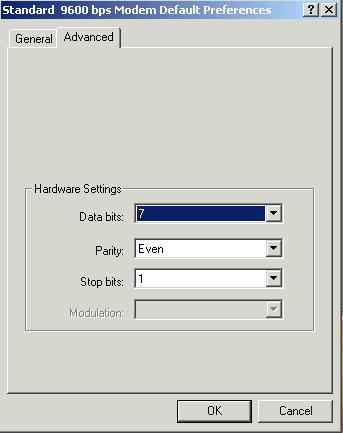
31 Windows Modem Properties window Click the Query Modem button to see that the Command and Response list is populated and that no error messages are displayed. If your modem requires additional commands to select the correct mode of operation, click the Advanced tab to see the following window. Consult your modem documentation on the commands available to you. Communication with the MT8xx meters is performed in compliance with the IEC 1107 standard with Mode C protocol. Type of communication: Serial asynchronous half-duplex ISO start bit 7 data bits 1 bit parity - even 1 stop bit Data transfer rate: 300, 600, 1200, 2400, 4800, 9600 Baud Appropriate modem settings: 31


32 32 MT830/MT831 Three-phase electronic multi-function meter
33 33

:")
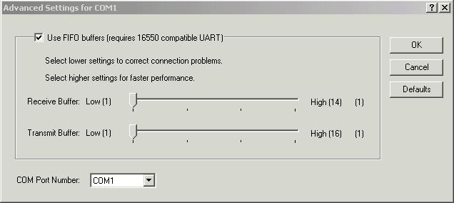
34 Check also FIFO buffer settings (especially for XP windows): Advanced 34
35 or 35
36 Appendix A: OBIS codes and data names OBIS code Data name Three phases energy registers, t = TOU registers (1,..n) 1-0:1.8.0 A+, Active energy import, total register 1-0:1.8.t A+, Active energy import, TOU register 1-0:1.9.0 A+, Active energy import in the billing period, total register 1-0:1.9.t A+, Active energy import in the billing period, TOU register 1-0:2.8.0 A-, Active energy export, total register 1-0:2.8.t A-, Active energy export, TOU register 1-0:2.9.0 A-, Active energy export in the billing period, total register 1-0:2.9.t A-, Active energy export in the billing period, TOU register 1-0:3.8.0 Q+=Q1+ Q2, Reactive energy import, total register 1-0:3.8.t Q+=Q1+ Q2, Reactive energy import, TOU register 1-0:3.9.0 Q+=Q1+ Q2, Reactive energy import in the billing period, total register 1-0:3.9.t Q+=Q1+ Q2, Reactive energy import in the billing period, TOU register 1-0:4.8.0 Q-=Q3+ Q4, Reactive energy export, total register 1-0:4.8.t Q-=Q3+ Q4, Reactive energy export, TOU register 1-0:4.9.0 Q-=Q3+ Q4, Reactive energy export in the billing period, total register 1-0:4.9.t Q-=Q3+ Q4, Reactive energy export in the billing period, TOU register 1-0:5.8.0 Q1, Reactive energy, inductive import, total register 1-0:5.8.t Q1, Reactive energy, inductive import, TOU register 1-0:5.9.0 Q1, Reactive energy, inductive import in the billing period, total register 1-0:5.9.t Q1, Reactive energy, inductive import in the billing period, TOU register 1-0:6.8.0 Q2, Reactive energy, capacitive import, total register 1-0:6.8.t Q2, Reactive energy, capacitive import, TOU register 1-0:6.9.0 Q2, Reactive energy, capacitive import in the billing period, total register 1-0:6.9.t Q2, Reactive energy, capacitive import in the billing period, TOU register 1-0:7.8.0 Q3, Reactive energy, inductive export, total register 1-0:7.8.t Q3, Reactive energy, inductive export, TOU register 1-0:7.9.0 Q3, Reactive energy, inductive export in the billing period, total register 1-0:7.9.t Q3, Reactive energy, inductive export in the billing period, TOU register 1-0:8.8.0 Q4, Reactive energy, capacitive export, total register 1-0:8.8.t Q4, Reactive energy, capacitive export, TOU register 1-0:8.9.0 Q4, Reactive energy, capacitive export in the billing period, total register 1-0:8.9.t Q4, Reactive energy, capacitive export in the billing period, TOU register 1-0:9.8.0 S+, Apparent energy import, total register 1-0:9.8.t S+, Apparent energy import, TOU register 1-0:9.9.0 S+, Apparent energy import in the billing period, total register 1-0:9.9.t S+, Apparent energy import in the billing period, TOU register 1-0: S-, Apparent energy export, total register 1-0:10.8.t S-, Apparent energy export, TOU register 1-0: S-, Apparent energy export in the billing period, total register 1-0:10.9.t S-, Apparent energy export in the billing period, TOU register Three phases cumulative demand registers, t = TOU registers (1,..n) 1-0:1.2.0 P+ cumulative demand total register 1-0:1.2.t P+ cumulative demand TOU register 1-0:2.2.0 P- cumulative demand total register 1-0:2.2.t P- cumulative demand TOU register 1-0:3.2.0 Q+ cumulative demand total register 1-0:3.2.t Q+ cumulative demand TOU register 1-0:4.2.0 Q- cumulative demand total register 1-0:4.2.t Q- cumulative demand TOU register 36
37 1-0:5.2.0 Q1 cumulative demand total register 1-0:5.2.t Q1 cumulative demand TOU register 1-0:6.2.0 Q2 cumulative demand total register 1-0:6.2.t Q2 cumulative demand TOU register 1-0:7.2.0 Q3 cumulative demand total register 1-0:7.2.t Q3 cumulative demand TOU register 1-0:8.2.0 Q4 cumulative demand total register 1-0:8.2.t Q4 cumulative demand TOU register 1-0:9.2.0 S+ cumulative demand total register 1-0:9.2.t S+ cumulative demand TOU register 1-0: S- cumulative demand total register 1-0:10.2.t S- cumulative demand TOU register Three phases momentary demand registers 1-0:1.4.0 P+ momentary demand register 1-0:2.4.0 P- momentary demand register 1-0:3.4.0 Q+ momentary demand register 1-0:4.4.0 Q- momentary demand register 1-0:5.4.0 Q1 momentary demand register 1-0:6.4.0 Q2 momentary demand register 1-0:7.4.0 Q3 momentary demand register 1-0:8.4.0 Q4 momentary demand register 1-0:9.4.0 S+ momentary demand register 1-0: S- momentary demand register Three phases last ended measurement period demand register 1-0:1.5.0 P+ last ended measurement period demand register 1-0:2.5.0 P- last ended measurement period demand register 1-0:3.5.0 Q+ last ended measurement period demand register 1-0:4.5.0 Q- last ended measurement period demand register 1-0:5.5.0 Q1 last ended measurement period demand register 1-0:6.5.0 Q2 last ended measurement period demand register 1-0:7.5.0 Q3 last ended measurement period demand register 1-0:8.5.0 Q4 last ended measurement period demand register 1-0:9.5.0 S+ last ended measurement period demand register 1-0: S- last ended measurement period demand register Three phases maximum demand registers, t = TOU registers (1,..n) 1-0:1.6.0 P+ maximum demand total register 1-0:1.6.t P+ maximum demand TOU register 1-0:2.6.0 P- maximum demand total register 1-0:2.6.t P- maximum demand TOU register 1-0:3.6.0 Q+ maximum demand total register 1-0:3.6.t Q+ maximum demand TOU register 1-0:4.6.0 Q- maximum demand total register 1-0:4.6.t Q- maximum demand TOU register 1-0:5.6.0 Q1 maximum demand total register 1-0:5.6.t Q1 maximum demand TOU register 1-0:6.6.0 Q2 maximum demand total register 1-0:6.6.t Q2 maximum demand TOU register 1-0:7.6.0 Q3 maximum demand total register 1-0:7.6.t Q3 maximum demand TOU register 1-0:8.6.0 Q4 maximum demand total register 1-0:8.6.t Q4 maximum demand TOU register 1-0:9.6.0 S+ maximum demand total register 1-0:9.6.t S+ maximum demand TOU register 1-0: S- maximum demand total register 37
38 38 1-0:10.6.t S- maximum demand TOU register Three phases quality instantaneous registers 1-0: Average current RMS 1-0: Average voltage RMS 1-0: Average power factor 1-0: Average frequency 1-0:11.7.h Average harmonics component in current, h harmonics component (1,..,8) 1-0:12.7.h Average harmonics component in voltage, h harmonics component (1,..,8) 1-0: ΣLi Active power (abs(qi+qiv)+(abs(qii+qiii)) Phase R energy registers, t = TOU registers (1,..n) 1-0: A+, Active energy import in phase R, total register 1-0:21.8.t A+, Active energy import in phase R, TOU register 1-0: A+, Active energy import in the billing period, phase R 1-0:21.9.t A+, Active energy import in the billing period TOU register, phase R 1-0: A-, Active energy export in phase R, total register 1-0:22.8.t A-, Active energy export in phase R, TOU register 1-0: A-, Active energy export in the billing period, phase R 1-0:22.9.t A-, Active energy export in the billing period TOU register, phase R 1-0: Q+=Q1+ Q2, Reactive energy import in phase R, total register 1-0:23.8.t Q+=Q1+ Q2, Reactive energy import in phase R, TOU register 1-0: Q+=Q1+ Q2, Reactive energy import in the billing period, phase R 1-0:23.9.t Q+=Q1+ Q2, Reactive energy import in the billing period TOU register, phase R 1-0: Q-=Q3+ Q4, Reactive energy export in phase R, total register 1-0:24.8.t Q-=Q3+ Q4, Reactive energy export in phase R, TOU register 1-0: Q-=Q3+ Q4, Reactive energy export in the billing period, phase R 1-0:24.9.t Q-=Q3+ Q4, Reactive energy export in the billing period TOU register, phase R 1-0: Q1, Reactive energy, inductive import in phase R, total register 1-0:25.8.t Q1, Reactive energy, inductive import in phase R, TOU register 1-0: Q1, Reactive energy, inductive import in the billing period, phase R 1-0:25.9.t Q1, Reactive energy, inductive import in the billing period TOU register, phase R 1-0: Q2, Reactive energy, capacitive import in phase R, total register 1-0:26.8.t Q2, Reactive energy, capacitive import in phase R, TOU register 1-0: Q2, Reactive energy, capacitive import in the billing period, phase R 1-0:26.9.t Q2, Reactive energy, capacitive import in the billing period TOU register, phase 1-0: R Q3, Reactive energy, inductive export in phase R, total register 1-0:27.8.t Q3, Reactive energy, inductive export in phase R, TOU register 1-0: Q3, Reactive energy, inductive export in the billing period, phase R 1-0:27.9.t Q3, Reactive energy, inductive export in the billing period TOU register, phase R 1-0: Q4, Reactive energy, capacitive export in phase R, total register 1-0:28.8.t Q4, Reactive energy, capacitive export in phase R, TOU register 1-0: Q4, Reactive energy, capacitive export in the billing period, phase R 1-0:28.9.t Q4, Reactive energy, capacitive export in the billing period TOU register, phase 1-0: R S+, Apparent energy import in phase R, total register 1-0:29.8.t S+, Apparent energy import in phase R, TOU register 1-0: S+, Apparent energy import in the billing period, phase R 1-0:29.9.t S+, Apparent energy import in the billing period TOU register, phase R 1-0: S- Apparent energy export in phase R, total register 1-0:30.8.t S- Apparent energy export in phase R, TOU register 1-0: S-, Apparent energy export in the billing period, phase R 1-0:30.9.t S-, Apparent energy export in the billing period TOU register, phase R Phase R cumulative demand register, t = TOU registers (1,..n) 1-0: P+ cumulative demand in phase R total register 1-0:21.2.t P+ cumulative demand in phase R TOU register 1-0: P- cumulative demand in phase R total register
MT372 Three-phase electronic meter with built-in modem or RS485 communication interface
 Energy Measurement and Management MT372 Three-phase electronic meter with built-in modem or RS485 communication interface Technical Description Version 1, 09.06. 2005 Content: MT372 Three-phase electronic
MT830/MT831. Technical Description. Three-phase electronic multi-function meter for industry EAD Version 1.7,
 MT830/MT831 Three-phase electronic multi-function meter for industry Technical Description EAD 020 611 368 Version 1.7, 27.05.2013 MT830-MT831_TD_eng_V1.7.docx Table of contents: 1. List of standards...3
MT174 Three-Phase Static Electricity Multi Tariff Meter with Maximum Demand Indicator and Load-profile
 Energy Measurement and Management MT174 Three-Phase Static Electricity Multi Tariff Meter with Maximum Demand Indicator and Load-profile Technical Description Version 1.0, 05.05.2010 Index: MT174 Electronic
MT174 Three-Phase Static Electricity Multi Tariff Meter with Maximum Demand Indicator and Load-profile
 Energy Measurement and Management MT174 Three-Phase Static Electricity Multi Tariff Meter with Maximum Demand Indicator and Load-profile Technical Description Version 1.2, 18.08.2011 Index: MT174 - Electronic
ME162 Single-Phase Electronic Meter
 Energy Measurement and Management ME162 Single-Phase Electronic Meter Technical Description Version 1.1, 02.06. 2006 Index: ME162 Electronic single-phase time-of-use kwh-meter... 3 1. Meter appearance...
ME371, MT371 Single- and Three-Phase Electronic Meters with Built-in DLC Communication Channel
 Energy Measurement and Management ME371, MT371 Single- and Three-Phase Electronic Meters with Built-in DLC Communication Channel ME372, MT375 Single- and Three-phase Electronic Meters with Built-in GSM/GPRS
ME371, MT371 Single- and Three-phase electronic meters with built-in DLC communication channel
 Energy Measurement and Management ME371, MT371 Single- and Three-phase electronic meters with built-in DLC communication channel ME372, MT372 Single- and Three-phase electronic meters with built-in GSM/GPRS
MT173 Three-Phase Electronic Multi Tariff Meter with Maximum Demand Indicator
 Energy Measurement and Management MT173 Three-Phase Electronic Multi Tariff Meter with Maximum Demand Indicator Technical Description Version 1.0, 14.11.2006 Index: MT173 Electronic three-phase time-of-use
E550 Series 2. Electricity Meters IEC/MID Industrial and Commercial ZMG310AR/CR. Technical Data
 Electricity Meters IEC/MID Industrial and Commercial ZMG310AR/CR E550 Series 2 Technical Data Building on its tradition of industrial meters, Landis+Gyr is now bringing out the E550 Series 2, the latest
E550 Series 2. Electricity Meters IEC/MID Industrial and Commercial ZMG400AR/CR. Technical Data
 Electricity Meters IEC/MID Industrial and Commercial ZMG400AR/CR E550 Series 2 Technical Data Building on its tradition of industrial meters, Landis+Gyr is now bringing out the E550 Series 2, the latest
MD300 and MT300. Technical Description
 20.11.2000 2 / 24 CONTENTS 1. METER TYPE DESIGNATION... 6 2. TECHNICAL AND FUNCTIONAL DESCRIPTION... 7 2.1. BASIC MEASURING PRINCIPLE... 7 2.2. MEASURING SYSTEM... 7 2.2.1. Energy measurement with a SMART
Energy Meters for DIN Rail Mounting Electric energy meter WS0101, WS0102,WS1102 WS0301, WS0302,WS1302
 Energy Meters for DIN Rail Mounting Electric energy meter WS0101, WS0102,WS1102 WS0301, WS0302,WS1302 Direct connection up to 65 A (WSx10x) Connection with current transformer (WSx30x) Industrial or meters
E650 Series 3. Electricity Meters IEC/MID Industrial and Commercial ZMD402AT/CT, ZFD402AT/CT. Technical Data
 Electricity Meters IEC/MID Industrial and Commercial ZMD402AT/CT, ZFD402AT/CT E650 Series 3 Technical Data Building on its tradition of industrial meters, Landis+Gyr has developed the E650 Series 3, the
Measuring centers MC7x0 series Multifunction Meter MC740
 Measuring centers MC7x0 series Multifunction Meter MC740 o Measurements of instantaneous values of more than 130 quantities (U, I, P, Q, S, PF, PA, f, φ, THD, MD, energy, energy cost by tariffs, etc.)
Introduction DIN rail mounted electricity meters
 Introduction DIN rail mounted electricity meters Modular DIN Rail Products offer a wide range of functions to be integrated in electrical installations with significant benefits for the user. DIN rail
Environmental Influences. Display. Inputs and Outputs. Electromagnetic Compatibility. Communication Interfaces. Insulation Strenght.
 Electricity Meters IEC INDUSTRIAL+COMMERCIAL Landis+Gyr Dialog ZMG310AR/CR TECHNICAL DATA Frequency Nominal Frequency fn 50 or 60 Hz tolerance ± 2 % Mesurement Accuracy Accuracy ZMG310xR active energy
SULTANATE OF OMAN METERING AND DATA EXCHANGE CODE
 1.0 GENERAL SULTANATE OF OMAN METERING AND DATA EXCHANGE CODE STANDARD: OES-22F THREE PHASE KILOWATT-HOUR DIGITAL METERS, CURRENT TRANSFORMER OPERATED, CONNECTED FOR SERVICE CONNECTIONS Electronic three
RI-F200 Series. Single and Three Phase Multifunction Energy Meter. Telephone : +44 (0) Displayed Parameters
 Displayed Parameters") RI-F200 Series Single and Three Phase Multifunction Energy Meter DIN 96 panel mounted -/1A or -/5A current transformer input Single phase or three phase network compatible Programmable voltage and current
RI-F200 Series Single and Three Phase Multifunction Energy Meter DIN 96 panel mounted -/1A or -/5A current transformer input Single phase or three phase network compatible Programmable voltage and current
NETWORK ANALYZERS Analyzers
 CONTENTS PRODUCTS RANGE NA.03 NETWORK ANALYZER - LCC NETWORK ANALYZER - LCA NETWORK ANALYZER - LDA NETWORK ANALYZER - LAB96 NETWORK ANALYZER - LABM NA.04 NA.06 NA.09 NA.10 NA.13 NETWORK ANALYZER - LCCM
PRELIMINARY DATA SHEET RI-D140. Three Phase Multifunction DIN Rail Energy Meter (MID Certified) MID
 MID") RI-D140 Three Phase Multifunction DIN Rail Energy Meter (MID Certified) Four module DIN rail mounted Energy pulse LED True RMS measurement Cost effective and accurate Modbus communication -/1A or -/5A
RI-D140 Three Phase Multifunction DIN Rail Energy Meter (MID Certified) Four module DIN rail mounted Energy pulse LED True RMS measurement Cost effective and accurate Modbus communication -/1A or -/5A
INDUSTRIAL+COMMERCIAL ZMG400AR/CR, ZFG400AR/CR TECHNICAL DATA. IEC-specific data. Current. Measurement Accuracy. Measurement Behaviour.
 Electricity Meters IEC/MID INDUSTRIAL+COMMERCIAL Landis+Gyr Dialog ZMG400AR/CR, ZFG400AR/CR TECHNICAL DATA IEC-specific data Current Nominal Current I n 1 A, 5 A, 5 1 A Maximal Current I max metrological
Energy Management Energy Analyzer Type EM210 MID
 Energy Management Energy Analyzer Type Multi-use housing: for both DIN-rail and panel mounting applications MID annex MI-003 (Measuring Instruments Directive) compliant Class B (kwh) according to EN50470-3
ZMD405AT/CT, ZFD405AT/CT, ZMD410AT/CT, ZFD410AT/CT
 Electricity Meters IEC/MID Industrial and Commercial ZMD405AT/CT, ZFD405AT/CT, ZMD410AT/CT, ZFD410AT/CT E650 Series 3 Technical Data Building on its tradition of industrial meters, Landis+Gyr has developed
RI-D440. Three Phase easywire Multifunction DIN Rail Energy Meter. Telephone : +44 (0) Displayed Parameters
 Displayed Parameters") RI-D440 Three Phase easywire Multifunction DIN Rail Energy Meter Four module DIN rail mounted Energy pulse LED 330mV Input from easywire CTs (or -/1A and -/5A current transformer input with TAS-SCTEWA
RI-D440 Three Phase easywire Multifunction DIN Rail Energy Meter Four module DIN rail mounted Energy pulse LED 330mV Input from easywire CTs (or -/1A and -/5A current transformer input with TAS-SCTEWA
INDUSTRIAL+COMMERCIAL ZMD400AR/CR, ZFD400AR/CR TECHNICAL DATA. Frequency. IEC-specific data. Current. Measurement Accuracy.
 Electricity Meters IEC INDUSTRIAL+COMMERCIAL Landis+Gyr Dialog ZMD400AR/CR, ZFD400AR/CR TECHNICAL DATA Frequency Nominal Frequency f n 50 or 0 Hz tolerance ± 2% IEC-specific data Current Nominal Current
Energy Management Energy Meter Type EM21 72R Retro-Fit
 Energy Management Energy Meter Type EM21 72R Retro-Fit Including 3 miniature split-core current sensors 10mm (90A), 16mm (150A) and 24mm (250A) diameter holes Class A (kwh) according to EN50470-3 Class
Energy Management Energy Analyzer Type EM210
 Energy Management Energy Analyzer Type EM210 Multi-use housing: for both DIN-rail and panel mounting applications Current inputs AV option: CT 5A Current inputs MV option: current sensor 333 mv (CTV series)
MT 560/UMT TRANSDUCER & ANALYZER
 MT 560/UMT 560 - TRANSDUCER & ANALYZER USE The MT 560/UMT 560 multi transducer and analyzer is used for a permanent analysis of electricity supply quality in compliance with the SIST EN 50160 standard.
1 2 3 GridVis Pulse output 2 tariffs Modbus MID M-Bus
 speicher MID energy meter ECSEM series Emax 2 Tariffs GridVis 7 Tariffs 8 Tariffs 14 Tariffs 0,2 kwh Class 0,5 kwh Class 1,0 kwh Class Pulse output Tarife 2 tariffs Messgenauigkeit Modbus MID M-Bus eratureingang
Energy Management Energy Meter Type EM340
 Energy Management Energy Meter Type EM340 Digital input (for tariff management Easy connection or wrong current direction detection Certified according to MID Directive (option PF only: see how to order
INSTALLATION MANUAL. Model: Smart Analyzer Manufacturer: Smart Impulse. Power meter with consumption breakdown by use 03/12/13
 INSTALLATION MANUAL Model: Smart Analyzer Manufacturer: Smart Impulse Power meter with consumption breakdown by use 03/12/13 Table of contents Table of contents... 2 1. Introduction... 3 2. Installation
Energy Management Energy Meter GM3T E GM3T-RS485 E
 Energy Management Energy Meter GM3T E09 814 96 GM3T-RS485 E09 816 65 Certified according to MID Directive Product Description Three-phase energy meter with removable front LCD display unit. The same unit
DELTAplus. DIN Rail Mounted electricity meters. Technical Documentation
 DIN Rail Mounted electricity meters Technical Documentation Table of Contents DELTAplus General Description... 4 Chapter 1: Assortment... 5 Assortment Direct connected meters... 6 Assortment Transformer
Energy Management Energy Meter Type EM111
 Energy Management Energy Meter Type EM111 Easy connection or wrong current direction detection Other versions available (not certified, option X: see how to order on the next page Single phase energy meter
Energy Management Energy Meter Type EM112
 Energy Management Energy Meter Type EM112 Easy connection or wrong current direction detection Other versions available (not certified, option X: see how to order on the next page Single phase energy meter
Moving Test - MT3000
 Moving Test - MT3000 Three-Phase Portable Test System Keep ahead with Modular Design The Modular Concept The MT3000 is based on a real modular design concept to provide the greatest possible flexibility
Power Meter Series PM3200 Functions and characteristics
 Functions and characteristics PB108433 This PowerLogic Power meter offers basic to advanced measurement capabilities. With compact size and DIN rail mounting, the PM3200 allows mains and feeders monitoring
Energy Management Energy Analyzer Type EM111
 Energy Management Energy Analyzer Type EM111 Single phase energy analyzer Class 1 (kwh according to EN62053-21 Class B (kwh according to EN50470-3 Accuracy ±0.5% RDG (current/voltage Direct current measurement
TECHNICAL DESCRIPTION THREE-PHASE SUBSTATION ELECTRONIC METERS
 HELLENIC ELECTRICITY DISTRIBUTION NETWORK OPERATOR S.A. NOTICE OF CALL FOR TENDERS No ND-207 PROJECT: Pilot Telemetering and Management System for the Electric Power Supply Demand by Residential and Small
PLA 33. Power line analyzer. User and service manual. version 2.4
 PLA 33 Power line analyzer User and service manual version 2.4 Content. Front control panel and terminal plate...3 7.2.2. System frequency setting...0 2. Device description...4 7.2.3. Password protection...0
RISH EM 3490 SS Kilowatt Hour Energy Meter With Rs485 RISH EM 3490 SS. Application : Product Features: Indication: Pulse Indication:
 Application : RISH Master 3490 SS is a 96mm x 96mm panel mounted kilowatt hour meter it measures active energy with class 1.0 accuracy having auto-resetting 8 digit seven segment LED counter. The unit
Centrale de mesure Power Meter PM500 Merlin Gerin
 Notice d'installation et d'utilisation Installation and user manual Centrale de mesure Power Meter PM500 Merlin Gerin 059473_D Introduction and description Package contents c one PM500 power meter with
Side view View from below Rear view
 Dimension diagrams All dimensions in mm Side view View from below Rear view Cut out: 138 +0,8 x 138 +0,8 mm Typical connection SPS SPS 11 12 13 14 15 16 1 2 3 4 5 6 7 8 9 10 DSUB-9 5 4 3 2 1 8 7 6 5 4
U1601 ENERGY CONTROL SYSTEM
 3-348-844-03 4/8.05 64 processing channels physical inputs or LON meter outputs can be assigned for the calculation of energy, power and costs Energy Control Language for the programming of analysis, monitoring
RISH PQM. Power Quality Monitor. Preliminary Datasheet subject to change without notice. Individual Harmonics measurement upto 56th Harmonics
 Power Quality Monitor Individual Harmonics measurement upto 56th Harmonics True representation of Voltage & Current waveforms. Phasor Representation of All 3 phases for system analysis Real Time Clock
PRELIMINARY DATA SHEET. RI-F400 Series. easywire Single and Three Phase Multifunction Energy Meter
 Telephone : 44 (0) 1245 428500 PRELIMIARY DATA SHEET RIF400 Series easywire Single and Three Phase Multifunction Energy Meter DI 96 panel mounted 330mV Input from easywire CTs (or /1A and /5A current transformer
Integra 1560 and 1580 Digital Transducer Systems
 Integra 1560 and 1580 multi function transducers provide high accuracy
INSTRUCTION MANUAL. Power Factor Controller - 12 steps Model A12 NOKIAN CAPACITORS. Power Factor Controller A12
 INSTRUCTION MANUAL Power Factor Controller - 12 steps Model A12 NOKIAN CAPACITORS Power Factor Controller A12 1. CONTENTS 1. CONTENTS 1 2. FEATURES 2 3. INSTALLATION, CONNECTION AND APPLYING POWER 2 4.
PREMIER INSTALLATION AND OPERATING INSTRUCTIONS
 PREMIER INSTALLATION AND OPERATING INSTRUCTIONS Copyright 2002-2006, PRI Ltd. 9600-3003-2 Issue C Information contained within this document is subject to change without notice and does not represent a
ENA33LCD. Power line analyzer. User and service manual. Obrezija 5 SI-1411 Izlake
 ENA33LCD Power line analyzer User and service manual version 2.9 (FW version 6.8 and newer) ETI, d.o.o. Obrezija 5 SI-1411 Izlake www.etigroup.eu/products-services 1. Front control panel and terminal plate
sw rev. 55B DEVICE FOR THE PERMANENT CONTROL OF INSULATION ON THE SUPPLY LINES IN MEDICAL PRACTICE PLACES INSTALLATIONS
 INSTRUCTIONS MANUAL IM831-U v0.92 HRI-R40W sw rev. 55B DEVICE FOR THE PERMANENT CONTROL OF INSULATION ON THE SUPPLY LINES IN MEDICAL PRACTICE PLACES INSTALLATIONS INDEX: GENERAL TYPES ACESSORIES AND OPTIONS
XP2-R Power and Reverse Power Relay
 XP2-R Power and Reverse Power Relay Manual XP2-R (Revision C) Woodward Manual XP2-RE Woodward reserves the right to update any portion of this publication at any time. Information provided by Woodward
INDUSTRIAL+COMMERCIAL ZMD310AT/CT TECHNICAL DATA. Measurement Accuracy. Measurement Behaviour. MID-specific data. Current (for Class B) General
 General") Electricity Meters IEC INDUSTRIAL+COMMERCIAL Dialog ZMD310AT/CT TECHNICAL DATA Maximal Current I max metrological selectable 40, 60, 80, 100, 120 A thermal 120 A Short Circuit 10 ms 5000 A Measurement
Electricity Meters IEC INDUSTRIAL+COMMERCIAL Dialog ZMD310AT/CT TECHNICAL DATA Maximal Current I max metrological selectable 40, 60, 80, 100, 120 A thermal 120 A Short Circuit 10 ms 5000 A Measurement
Energy Management Energy Analyzer Type EM112
 Energy Management Energy Analyzer Type EM112 Single phase energy analyzer Class 1 (kwh according to EN62053-21 Class B (kwh according to EN50470-3 Accuracy ±0.5% RDG (current/voltage Direct current measurement
Energy Measurement and Management. ME381 and MT381 User manual
 Energy Measurement and Management ME381 and MT381 User manual Document code: EAK 020.615.258 Version: 1.01 Date: 29.10.2013 i. About the User manual ME381 and MT381 User manual is intended to present the
XP2-R Power and reverse power relay. (January 2006) Manual XP2-R (Revision New)
 Manual XP2-R (Revision New)") XP2-R Power and reverse power relay (January 2006) Manual XP2-R (Revision New) Woodward Manual XP2-R GB Woodward Governor Company reserves the right to update any portion of this publication at any time.
XP2-R Power and reverse power relay (January 2006) Manual XP2-R (Revision New) Woodward Manual XP2-R GB Woodward Governor Company reserves the right to update any portion of this publication at any time.
ELECTRICAL NETWORK RECORDER - MC 750 ELECTRICAL NETWORK ANALYZER -MC 760 ENERGY METER - MC 720 POWER METER - MC 710 MULTIFUNCTION METER - MC 740
 ELECTRICAL NETWORK ANALYZER -MC 760 ELECTRICAL NETWORK RECORDER - MC 750 MULTIFUNCTION METER - MC 740 ENERGY METER - MC 720 POWER METER - MC 710 WE RECORD QUANTITIES OF ELECTRICAL NETWORK, MEASURE INSTANTANEOUS
BU: EPBP GPG: DIN Rail Products Devices for the permanent control of insulation on supply lines for medical locations ISOLTESTER-DIG-RZ/RS/PLUS
 INSTRUCTION MANUAL BU: EPBP GPG: DIN Rail Products Devices for the permanent control of insulation on supply lines for medical locations ISOLTESTER-DIG-RZ/RS/PLUS 1/23 More information than that reported
A balance between cost and benefits without compromising maximum quality. Ideal, both for industry and commercial buildings.
 CIRWTT ENERGY METERS CIRWTT is a family of multi-function energy meters capable of satisfying the most demanding requirements of energy measurement systems. Other features to highlight are quality, accuracy,
Energy Management Energy Analyzer Type EM280-72D
 Energy Management Energy Analyzer Type EM280-72D Equivalent to Class 1 (kwh) of EN62053-21 (EM280 base only) Equivalent to Class 2 (kvarh) of EN62053-23 (EM280 base only) Virtual meter (sum of two 3-phase
Energy Management Energy Meter with plug-in Output Modules Type EM4-DIN
 Energy Management Energy Meter with plug-in Output Modules Type EM4-DIN Degree of protection (front): IP 40 Front dimensions: 9 DIN modules RS 422/485 Serial port by means of optional module Dual pulse
Measuring Transducer MT4xx series Programmable AC Current Transducer MT418
 Measuring Transducer MT4xx series Programmable AC Current Transducer MT418 o RMS AC current or frequency measurements o Current auto range measurements up to 12 A o Frequency measurement range 16 400 Hz
DIGEM f 96 x 48 EK. Applications. Description
 3-349-002-03 1/7.98 Front panel dimensions: 96 x 48 mm LED display: red or green, 14 mm high Max. display range: 19 999 to + 32 765 Modular connectors for flexible use Simple adjustments at front panel
Energy Management Energy Analyzer Type EM270-72D
 Energy Management Energy Analyzer Type EM270-72D RS485 dual port for daisy chain connection (optional) 2 programmable pulsating outputs (optional) Easy connections management (selectable) disabled by default
MID. Energy Management Energy Meter Type EM23 DIN. Product Description. Type Selection. How to order EM23 DIN AV9 3 X O1 PF A EM23 DIN
 Energy Management Energy Meter Type EM23 DIN Certified according to MID Directive (option PF only): see how to order below Other version available (not certified, option X): see how to order on the next
Energy Management Three-phase energy meter with output modules Type EM4-DIN
 Energy Management Three-phase energy meter with output modules Type EM4-DIN Class 1 (active energy) Class 2 (reactive energy) Three-phase multi-function energy meter Back-lighted LCD display 3 1 / 2 DGT
Power quality Harmonics up to 40th harmonic Unbalance, rotary field indication Distortion factor THD-U / THD-I
 Harmonics Temperature input Measurement accuracy 0.5 Memory 4 MByte UMG 104 Energy measurement device for DIN rails Communication Profibus (DP / V0 optional) Modbus RTU Power quality Harmonics up to 40th
M-Bus Master MultiPort 250L Installation and User Guide
 Installation and User Guide Kamstrup A/S Industrivej 28, Stilling DK-8660 Skanderborg T: +45 89 93 10 00 info@kamstrup.com kamstrup.com Contents 1 Introduction 3 1.1 Design 3 2 Functionality 4 2.1 Overview
High-set undervoltage stage with definitetime. or inverse definite minimum time (IDMT) characteristic. Low-set undervoltage stage with definitetime
 characteristic. Low-set undervoltage stage with definitetime") Issued: 5.06.999 Status: 5.06.999 Version: B/09..00 Data subject to change without notice Features Overvoltage and undervoltage protection Single- or three-phase operation High-set overvoltage stage with
Issued: 5.06.999 Status: 5.06.999 Version: B/09..00 Data subject to change without notice Features Overvoltage and undervoltage protection Single- or three-phase operation High-set overvoltage stage with
Computer-14d - xx - 144a
 POWER FACTOR REGULATOR Computer-14d - xx - 144a INSTRUCTION MANUAL ( M 981 602 / 98B ) (c) CIRCUTOR S.A. -------- POWER FACTOR REGULATOR COMPUTER- 14d --------- Page 2 1.- POWER FACTOR REGULATORS COMPUTER-14d-144a
MID. Energy Management Energy Meter Type EM33 DIN. Product Description. How to order EM33 DIN AV3 3 X XS PF. Type Selection EM33 DIN
 Energy Management Energy Meter Type EM33 DIN Easy connections management Certified according to MID Directive (option PF only): see how to order below Other version available (not certified, option X):
PEM353. Universal measuring device
 353 Universal measuring device 353_D00335_00_D_XXEN/06.2018 353 Universal measuring device Product description The digital universal measuring device 353 is used to record and display measured quantities
MID. RI-F300 Series. easywire Single and Three Phase Multifunction Energy Meter (MID Certified) MID
 MID") Telephone : 44 (0) 1245 428500 RIF300 Series MID easywire Single and Three Phase Multifunction Energy Meter (MID Certified) DI 96 panel mounted 1A Input from easywire CTs Single phase or three phase network
Telephone : 44 (0) 1245 428500 RIF300 Series MID easywire Single and Three Phase Multifunction Energy Meter (MID Certified) DI 96 panel mounted 1A Input from easywire CTs Single phase or three phase network
High precision measurement system for current and voltage IHC-A/B-RM01/03
 Measurement Offset-free and low-noise 16 bit data acquisition system ISA-ASIC Internal sample rate 3,500 Hz Communication Standard RS232- or RS485 interface Advantages Direct measurement on the bus bar
Dimension diagrams All dimensions in mm. Typical connection UMG 604-PRO. Power Analyser UMG 604-PRO. Front view. Side view. Versorgungsspannung
 Dimension diagrams All dimensions in mm 73 mm 10 mm 35 mm 44 mm 90 mm 90 mm 107,5 mm 50 mm 76 mm 82 mm Front view Side view Typical connection An. In R32 RS485 Dig. I/O Versorgungsspannung Auxiliary Supply
PRODUCT LEAFLET AUGIER-BOX. Remote Monitoring Unit for Street Lighting /07/2011
 PRODUCT LEAFLET AUGIER-BOX Remote Monitoring Unit for Street Lighting 1 60 11432-04/07/2011 Put a TECHNICIAN in each street lighting cabinet, and control them 24H per day! The Augier-Box Programmable Logic
XF2 Frequency Relay. Manual XF2 (Revision A)
") XF2 Frequency Relay Manual XF2 (Revision A) Woodward Manual XF2 GB Woodward Governor Company reserves the right to update any portion of this publication at any time. Information provided by Woodward Governor
XF2 Frequency Relay Manual XF2 (Revision A) Woodward Manual XF2 GB Woodward Governor Company reserves the right to update any portion of this publication at any time. Information provided by Woodward Governor
Technical Data Sheet. x1000. kwh R Y B
 Technical Data Sheet x1000 Von kwh IRev 3600 imp /kwh R Y B is a compact multifunction instrument which is a 96mm x 96mm panel mounted kilowatt hour meter it measures active energy with class 1.0 accuracy
SITRANS F flowmeters SITRANS F M. Transmitter Transmag 2 with sensor 911/E 4/77. Overview
 Overview Design The complete flowmeter consists of a flow sensor and an associated transmitter from the Transmag 2 for pulsed alternating field. These are available as remote and compact versions ( 911/E
Delta Meter. ABB Cewe
 Contents Electricity metering... 2 General description... 3 Standard assortment/accessories... 4 Product overview... 6 Wiring diagrams... 8 Technical data...9 Symbols and definitions... 10 Dimensions...
Power quality Harmonics up to 40th harmonic Rotary field components Distortion factor THD-U / THD-I
 Memory 256 MB Alarm management Residual current measurement Homepage Ethernet-Modbus gateway BACnet (optional) UMG 96 RM-E Power analyser with Ethernet and RCM Communication Modbus (RTU, TCP, Gateway)
Three phase CT Connection Smart Meter s Technical Specification
 1 1.1 Country 1.2 Manufacturer Three phase CT Connection Smart Meter s Technical Specification General Information 1.3 Vendor 1.4 type of the Meter & Name 1.5 and number of sale List of clients referring
INSTRUCTIONS MANUAL DEVICE FOR THE PERMANENT CONTROL OF INSULATION ON THE SUPPLY LINES IN MEDICAL PRACTICE PLACES INSTALLATIONS HRI-R40W
 Page 2 / 16 INDEX: GENERAL TYPES ACESSORIES AND OPTIONS INSTALLATION WIRING DIAGRAMS CONNECTING TERMINALS DIAGRAMS WIRING DIAGRAM DESCRIPTION WORKING DESCRIPTION AND KEYBOARD WORKING DESCRIPTION AND PROGRAMMING
SUPPLY NETWORK ANALYZER CVM-96 SERIES
 SUPPLY NETWORK ANALYZER CVM-96 SERIES (Power Demand) INSTRUCTION MANUAL ( M 981 326 / 00B - GB) (c) CIRCUTOR S.A. ----- Supply network analyzer CVM-96 ------ User's manual --- Page No. 1 CVM-96 SUPPLY
ULTRA RAPID POWER QUALITY ANALYZER
 ULTRA RAPID POWER QUALITY ANALYZER Ultra rapid (cycle by cycle) advanced electrical network analysis Complete network harmonics analysis, up to 63 rd harmonic High visibility, 5 graphic LCD screen with
MICROPROCESSOR-BASED METERING EQUIPMENT SECTION 16901C PART 2
 PART 1 PART 2 PRODUCTS 2.01 MANUFACTURERS A. Eaton products B.. C.. The listing of specific manufacturers above does not imply acceptance of their products that do not meet the specified ratings, features
SPECIFICATION FOR OVERCURRENT RELAYS
 SPECIFICATION FOR OVERCURRENT RELAYS 1/9 1. Procedure A manufacturer willing to classify an overcurrent relay according to this specification should provide: A complete file providing a clear, unambiguous
XUA1 AC Voltage and phase balance relay. (August 1996) Manual XUA1 (Revision New)
 Manual XUA1 (Revision New)") XUA1 AC Voltage and phase balance relay (August 1996) Manual XUA1 (Revision New) Woodward Manual XUA1 GB Woodward Governor Company reserves the right to update any portion of this publication at any time.
XUA1 AC Voltage and phase balance relay (August 1996) Manual XUA1 (Revision New) Woodward Manual XUA1 GB Woodward Governor Company reserves the right to update any portion of this publication at any time.
B850 Boiler House Energy Monitor
 Local regulations may restrict the use of this product to below the conditions quoted. In the interests of development and improvement of the product, we reserve the right to change the specification without
PRELIMINARY DATA SHEET. RI-F300 Series. easywire Single and Three Phase Multifunction Energy Meter (MID Certified) MID
 MID") RIF300 Series easywire Single and Three Phase Multifunction Energy Meter (MID Certified) DI 96 panel mounted 330mV Input from easywire CTs (or /1A and /5A current transformer input with TASSCTEWA module)
RIF300 Series easywire Single and Three Phase Multifunction Energy Meter (MID Certified) DI 96 panel mounted 330mV Input from easywire CTs (or /1A and /5A current transformer input with TASSCTEWA module)
XU2-AC AC voltage relay. (Februar 1997) Manual XU2-AC (Revision New)
 Manual XU2-AC (Revision New)") XU2-AC AC voltage relay (Februar 1997) Manual XU2-AC (Revision New) Woodward Manual XU2-AC GB Woodward Governor Company reserves the right to update any portion of this publication at any time. Information
XU2-AC AC voltage relay (Februar 1997) Manual XU2-AC (Revision New) Woodward Manual XU2-AC GB Woodward Governor Company reserves the right to update any portion of this publication at any time. Information
PQ-Box 100 Network Analyzer for Low-, Medium- and High-Voltage Networks
 GB Technical data Issue 06/2009 PQ-Box 100 Network Analyzer for Low-, Medium- and High-Voltage Networks Fault detection Evaluation of voltage quality according to EN50160 and IEC61000-2-2 Fault recorder
Electrical network management. Schneider Electric. PM3200 Technical Datasheet
 Electrical network management Schneider Electric PM3200 Technical Datasheet Functions and characteristics PB108433 This PowerLogic Power meter offers basic to advanced measurement capabilities. With compact
EASTRON SDM630MCT-RJV / SDM630MCT-RJA User Manual V1.1. Three phase multifunction din rail energy meter
 SDM630MCT-RJV-333mV SDM630MCT-RJA-00mA Three phase multifunction din rail energy meter Plug-in solution; labor saving; wiring mistake free Measures kwh KVarh, KW, Kvar, KVA, P, F, PF, Hz, dmd, V, A, THD,etc.
XUA1 - AC Voltage and phase balance relay
 XUA1 - AC Voltage and phase balance relay Contents 1. Applications and features 2. Design 3. Function 3.1 Voltage supervision 3.2 Unbalanced voltage supervision 4. Operation and settings 4.1 Setting of
MID. Energy Management Energy Analyzer Type EM11 DIN. Product Description. How to order EM11 DIN AV8 1 X O1 PF. Type Selection EM11 DIN
 Energy Management Energy Analyzer Type EM11 DIN Other versions available (not certified, option X): see how to order on the next page Product Description Class 1 (kwh) according to EN62053-21 Class B (kwh)
RS232 AC-DC VOLTAGE POWER AMPLIFIERS PCU-10K / 15K / 20K / 24K-AB/4G/HP PERFORMANCES APPLICATIONS DESCRIPTION COMMERCIAL REFERENCES
 PERFORMANCES High accuracy High stability Fast transients High inrush current facilities Wide bandwidth Very low distortion Quadrant change without transition Very low output impedance RS232 APPLICATIONS
C series Product brief
 Product brief Key applications Landlord sub-metering Object metering Meter performance Direct connected up to 0 ctive energy Low power consumption larm function Pulse output Installation Small size - 1
12/2 Product overview. 12/3 7KT1 14, 7KT1 53 E-counters. 12/9 7KT1 11, 7KT1 12 digital measuring devices. 12/11 7KT1 0 analog measuring devices
 BETA Measuring /2 Product overview /3 7KT1 14, 7KT1 53 E-counters /9 7KT1 11, 7KT1 digital measuring devices /11 7KT1 0 analog measuring devices / 7KT5 8 time and pulse counters /14 7KT5 5, 7KT5 6 time
HV / MV / LV electrical network quality analyzers Class A. Communication port: local, modem, integrated Ethernet, multi-point
 2010 MAP Range HV / MV / LV electrical network quality analyzers Class A > Network quality Analyzers PRODUCT ADVANTAGES COMPLIANT with the EN 61000-4-30 standard, Class A DETECTION of the fault LOCATION