ITG Electronics, Inc.
|
|
|
- Ezra Hubbard
- 6 years ago
- Views:
Transcription
1 Mitigating EMI Problems & Filter Selection By Rafik Stepanian
2 EMI Noise Generators A change of state (On/Off ) in an Electronic component has the potential to generate EMI. Typical examples are Electronic Switchers, Clocks, Electronic controls, Power Supplies, Inverters, Fluorescent lights, Motor Brushes, etc. EMI noise could; Conduct through the power lines and it could be; Common Mode, between Line or Neutral to Ground Differential Mode, between Line and Neutral Radiate through Air
3 Curtesy of EMC consultant, France
4 How to mitigate EMI? EMI is known as Black Magic. No one wants to deal with it because it has no perceived market value, it is an economical burden which is ignored until one starts reading the paragraphs in fine print which reads; The system must meet the EMI requirements of Which means it is TIME FOR 911 CALL Most of the times the engineer is in a lab and the unit failed EMI test and the most common question is Do you have a filter which passes MIL-STD-461 or
5 MIL-STD s and EN s Provide: EMI limits Detail test methods Test procedures Test apparatus What they don t or can t provide obviously is how much noise the DUT generates EMI filters are application specific and they provide: X db at certain frequency Off the shelf (OTS) filters are designed to attenuate CM noise above 150KHz for commercial applications The OTS filters are not suitable for most military applications because the EMI test frequency starts at 10KHz CM components have little effective below 100KHz, therefore DM components are necessary to suppress the lower frequency noise

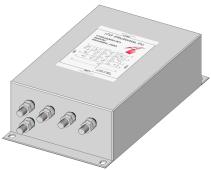
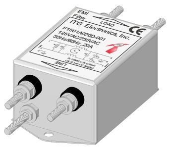
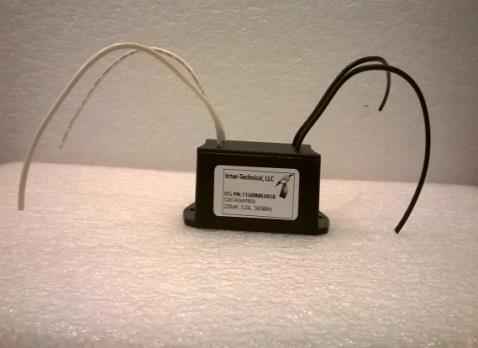
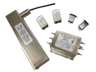
6 TYPICA EMI FILTERS
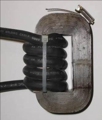
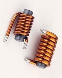

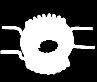
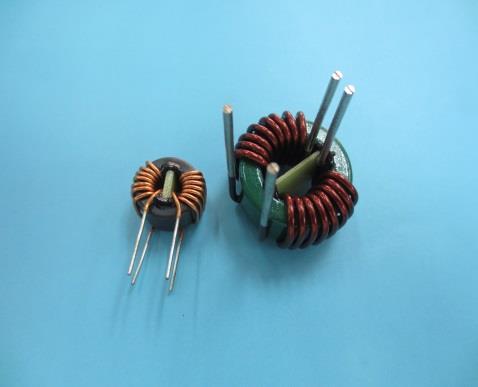
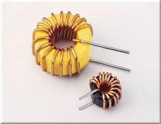
7 ITG Electronics, Inc Power Line Filters Components Common Mode Coil Differential Mode Coil

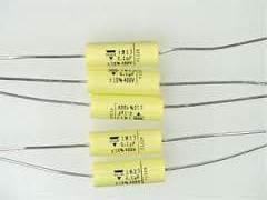
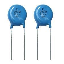
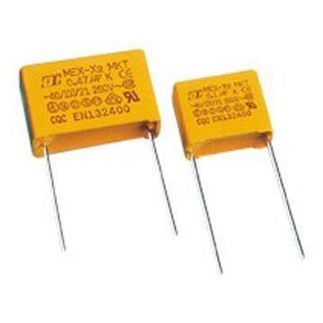

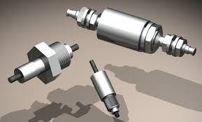
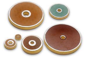
8 ITG Electronics, Inc X, Y or By-Pass Capacitors F/T Capacitor
9 Following are the minimum information required to start a filter design/selection Filter application Military, industrial or Commercial Voltage rating, DC or AC Power line frequency, 50/60/400Hz Current rating Leakage current Single or three phase Three phase Delta or WYE Required attenuation (db VS frequency) Or results from EMI test w/o a filter installed Available volume Mounting means Termination (fast-on, screw, Mil connectors, etc.) Environmental requirements
10 Things to know when choosing an EMI filter 1. In commercial world the conducted emissions measurement starts from 150KHz to 30MHz, the radiated Emissions starts from 30MHz to 300KHz, and up. 2. In military world the conducted emissions measurement starts from 10KHz to 10MHz, the radiated Emissions starts from 10MHz to 1GHz and up. 3. Whether in an EMI lab or in house performing EMI test if you are lucky the DUT will pass, but if it fails save/print the results. 4. Perform a Common Mode noise test save/print the results. 5. Record the failed frequency starting from the lowest frequency and corresponding db values above the limit line.
11 Continued; 6. If the failed frequencies are at 150KHz and up you may start with a simple LC or PI configuration filter. 7. Use the recorded data db Vs frequency and compare with data sheets provided by filter manufacturer and choose a filter and repeat EMI test. 8. If EMI test results are better but not quite there yet, what you need to know is each filter component in theory provide: 6dB additional attenuation when its value is doubled 6dB less attenuation when its value is cut in half 6dB additional attenuation per octave (every time the frequency is doubled) 20dB additional attenuation per decade (every time the frequency is multiplied by 10) Additional component increases the filters attenuation by 20 db Note: you may use the above during system simulation.
12 Typical filter circuit and it s attenuation response in ideal situation 6dB attenuation per Octave 20dB attenuation per Decade
13 2L 6dB more attenuation 1/2L, 6dB less attenuation
14 2xL & 2xC, 12dB more attenuation 1/2xL 1/2xC, 6dB less attenuation
15 Case Study EMI Filter Design based on EMI test results 480VAC 60Hz 200A Inverter

16 MIL STD-461, CE102 test results without EMI filter
17 Initial open frame prototype 500uH 10uF 500uH 10uF 0.01uF Phase A Phase A INPUT Phase B Phase B OUTPUT Phase C Phase C Case GND

18 MIL STD-461, CE102 test results with prototype filter
19 750uH 20uF 750uH 20uF 0.01uF Phase A Phase A INPUT Phase B Phase B OUTPUT Phase C Phase C Case GND

20 MIL STD-461, CE102 test results with final EMI filter installation
21 Does and don ts during electronic design Where possible: Use multilayer PCB design with ground planes in between layers Short traces where possible to reduce antenna affect Place noisy components in one area Avoid sharp (90 degree) trace bends, round off the trace edges and corners Use wire harness Separate noisy cables from power line cables If using shielded cables connect shield to ground at least one end Do not daisy chain ground wires, have one common ground and ground wires as short as possible Use shielding material around the covers and doors Make sure areas where shielded materials are used are not painted Read fine prints on your spec and if there is an EMI requirements make sure to leave space for an EMI filter. Perform EMI test during prototype design phase
22 Military and Commercial EMI test are performed in a 50 ohms system using LISN s (Line Impedance Stabilization Network) Conducted emissions testing is performed on power cables entering the equipment. The reason is to prevent EMI noise generated by electronics switches is contained in the chassis and will not transmit through the power cables and adversely effect the performance of other equipment connected to the same power line Military and commercial EMI spec provide limits and test procedures not solution guide lines If emissions measured exceeds the allowable limits EMI filters are required EMI Filters are bi-directional and they mitigate conducted emissions. They are most effective at lower frequencies and their harmonics at higher frequency spectrum To enhance the performance of the EMI filters they should be installed at the power line entering the equipment, preferably input terminals protruding out of the enclosure isolated from filter output terminals The isolation will prevent cross talk between input (dirty) and output (clean) terminals and will positively effects the radiated emissions test results
23 1. While in the EMI lab doing EMI test if the product fails, the very first thing to do is print the results. 2. Perform a Common Mode noise test (most labs know how to perform this test) and print the results. 3. Write down the failed frequency and corresponding db margin above the limit line. 4. In the commercial world the conducted emissions measurement starts from 150KHz to 30MHz, the radiated Emissions starts from 30MHz to 300KHz, or 1GHz depending on the product under test. 5. In the military world the conducted emissions measurement starts from 10KHz to 10MHz, the radiated Emissions starts from 10MHz to 1GHz and up depending on the product under test. 6. If the failed frequencies are at 150KHz and up you may start with a simple LC filter. Here is what you need to know, every element initially provides 6dB attenuation, an LC filter will provide total 12db attenuation above the cut off frequency. If the L or C or both component values are doubled, each will provide 6dB additional attenuation per element. 7. Each filter component element provides: a) 6dB attenuation per octave (every time the frequency is doubled) b) 20dB attenuation per decade (every time the frequency is multiplied by 10) c) 6dB attenuation when the value of a component is doubled d) 6dB less attenuation when the value of a component is cut in half e) Additional component adds 20dB attenuation
24 Conclusion The EMI solution once designed will work for years, as long as the filter components are properly selected for voltage fluctuation and maximum operating current and environmental requirements. EMI solutions do not need regularly scheduled maintenance. What is important is the manufacturing consistency of the system the EMI solutions are designed for. Any changes no matter how insignificant the they are it is recommended to repeat EMI test to prevent future costly field recalls because of EMI failure. As you can see EMI solution is not Black Magic it is based on a technology from past, which is reliable and most importantly it still works
25 Cost of Incorporating EMI solution
26 Worldwide Support Team: We work closely with customers on new design activity as well as supplies and demand management. Inventory in LA, Elmsford NY, Hong Kong and Shanghai, China to support regional demand. Our global help hotline: USA: (NY Office) USA: (PA Office) Japan: Taipei: Kaohsiung: Hong Kong: ShenZhen: Shanghai:
Common myths, fallacies and misconceptions in Electromagnetic Compatibility and their correction.
 Common myths, fallacies and misconceptions in Electromagnetic Compatibility and their correction. D. A. Weston EMC Consulting Inc 22-3-2010 These are some of the commonly held beliefs about EMC which are
ROD ANTENNA TESTING Complete article download from: EMI TESTING. Basic RE102 test (2-30 MHz)
") ROD ANTENNA TESTING Complete article download from: http://stevejensenconsultants.com/rod_ant.pdf EMI TESTING Steve Jensen Steve Jensen Consultants Inc. Sept. 26, 2005 Applicable for DO-160 sec. 21 and
ROD ANTENNA TESTING Complete article download from: http://stevejensenconsultants.com/rod_ant.pdf EMI TESTING Steve Jensen Steve Jensen Consultants Inc. Sept. 26, 2005 Applicable for DO-160 sec. 21 and
Reducing Motor Drive Radiated Emissions
 Volume 2, Number 2, April, 1996 Application Note 107 Donald E. Fulton Reducing Motor Drive Radiated Emissions Introduction This application note discusses radiated emissions (30 Mhz+) of motor drives and
Understanding and Optimizing Electromagnetic Compatibility in Switchmode Power Supplies
 Understanding and Optimizing Electromagnetic Compatibility in Switchmode Power Supplies 1 Definitions EMI = Electro Magnetic Interference EMC = Electro Magnetic Compatibility (No EMI) Three Components
Chapter 12 Digital Circuit Radiation. Electromagnetic Compatibility Engineering. by Henry W. Ott
 Chapter 12 Digital Circuit Radiation Electromagnetic Compatibility Engineering by Henry W. Ott Forward Emission control should be treated as a design problem from the start, it should receive the necessary
Common myths, fallacies and misconceptions in Electromagnetic Compatibility and their correction.
 Common myths, fallacies and misconceptions in Electromagnetic Compatibility and their correction. D. A. Weston EMC Consulting Inc 15-3-2013 1) First topic an introduction These are some of the commonly
CS101. Conducted Susceptibility CS101. CS101 Maximum Current. CS101 Limits. Basis For CS101 Limits. Comparison To MIL-STD Vdc or Less
 Conducted Susceptibility CS1 Raymond K. Adams Fischer Custom Communications, Inc. 20603 Earl Street Torrance, CA 90503 (3)303-3300 radams@fischercc.com CS1 Applicability DC and AC Input Power Leads Does
X2Y versus CM Chokes and PI Filters. Content X2Y Attenuators, LLC
 X2Y versus CM Chokes and PI Filters 1 Common Mode and EMI Most EMI compliance problems are common mode emissions. Only 10 s of uas in external cables are enough to violate EMC standards. 2 Common Mode
Suppression Techniques using X2Y as a Broadband EMI Filter IEEE International Symposium on EMC, Boston, MA
 Suppression Techniques using X2Y as a Broadband EMI Filter Jim Muccioli Tony Anthony Dave Anthony Dale Sanders X2Y Attenuators, LLC Erie, PA 16506-2972 www.x2y.com Email: x2y@x2y.com Bart Bouma Yageo/Phycomp
5. Maximum Conducted Output Power
 Report Number: F690501/RF-RTL009890-2 Page: 70 of 97 5. Maximum Conducted Output Power 5.1. Test setup EUT Attenuator Power sensor Note PC 5.2. Limit FCC 15.407 (a)(1)(iv) For client devices in the 5.15-5.25
The Causes and Impact of EMI in Power Systems; Part 1. Chris Swartz
 The Causes and Impact of EMI in Power Systems; Part Chris Swartz Agenda Welcome and thank you for attending. Today I hope I can provide a overall better understanding of the origin of conducted EMI in
EMC Design Guidelines C4ISR EQUIPMENT & SYSTEMS
 EMC Design Guidelines C4ISR EQUIPMENT & SYSTEMS 1.1. SHIELDING Enclosed structure (equipment box or chassis in outside RF environment) should provide at least 100 db of RF shielding at 1 MHz, 40 db at
Test Results #TR 4012, v1.0
 ITT Industries, Electronic Components/X2Y Attenuators Case Study of Filtered Connector Application in Blower Motor to Meet EMC Requirements Test Results #TR 4012, v1.0 DISCLAIMER: Information and suggestions
11 Myths of EMI/EMC ORBEL.COM. Exploring common misconceptions and clarifying them. MYTH #1: EMI/EMC is black magic.
 11 Myths of EMI/EMC Exploring common misconceptions and clarifying them By Ed Nakauchi, Technical Consultant, Orbel Corporation What is a myth? A myth is defined as a popular belief or tradition that has
Keysight Technologies Essential Capabilities of EMI Receivers. Application Note
 Keysight Technologies Essential Capabilities of EMI Receivers Application Note Contents Introduction... 3 CISPR 16-1-1 Compliance... 3 MIL-STD-461 Compliance... 4 Important features not required by CISPR
Differential-Mode Emissions
 Differential-Mode Emissions In Fig. 13-5, the primary purpose of the capacitor C F, however, is to filter the full-wave rectified ac line voltage. The filter capacitor is therefore a large-value, high-voltage
Prof. dr. ir. Johan CATRYSSE
 EMC: How to handle large machinery Prof. dr. ir. Johan CATRYSSE FMEC, KHBO, Oostende (BE) MICAS/ESAT, KULeuven (BE) 1 Overview 2 Large Machinery EMC Directive and Harmonised Standards TEMCA2 project Conducted
ELECTRICAL FILTERS. (Command Control Communications Computer & Intelligence) E 3 LINE FILTERS EMI LEMP NEMP HEMP TEMPEST
 E 3 LINE FILTERS EMI LEMP NEMP HEMP TEMPEST") ELECTRICAL FILTERS INTEGRATED PROTECTION OF C 4 I EQUIPMENT & FACILITIES (Command Control Communications Computer & Intelligence) E 3 LINE FILTERS EMI LEMP NEMP HEMP TEMPEST Electromagnetic Environmental
ELECTRICAL FILTERS INTEGRATED PROTECTION OF C 4 I EQUIPMENT & FACILITIES (Command Control Communications Computer & Intelligence) E 3 LINE FILTERS EMI LEMP NEMP HEMP TEMPEST Electromagnetic Environmental
LISN UP Application Note
 LISN UP Application Note What is the LISN UP? The LISN UP is a passive device that enables the EMC Engineer to easily distinguish between differential mode noise and common mode noise. This will enable
Unclassified Distribution A: Unlimited Public Release
 IMPACT OF INADVERTENT ELECTROMAGNETIC EMISSIONS ON ORGANIC VEHICLES THAT AFFECT THE TACTICAL COMMUNICATIONS OPERATING BANDS By Erick Ortiz and Frank A. Bohn US ARMY CERDEC Antennas & Spectrum Analysis
Electromagnetic Compatibility of Power Converters
 Published by CERN in the Proceedings of the CAS-CERN Accelerator School: Power Converters, Baden, Switzerland, 7 14 May 2014, edited by R. Bailey, CERN-2015-003 (CERN, Geneva, 2015) Electromagnetic Compatibility
DRB EVALUATION DATA
 EALUATION DATA TDK-Lambda PA634-53-01 INDEX 1. Evaluation Method PAGE 1.1 Circuit used for determination Circuit 1 used for determination... T-1 Steady state data Over current protection (OCP) characteristics
7. Transmitter Radiated Spurious Emissions and Conducted Spurious Emission
 7. Transmitter Radiated Spurious Emissions and Conducted Spurious Emission 7.1 Test Setup Refer to the APPENDIX I. 7.2 Limit According to 15.247(d), in any 100 khz bandwidth outside the frequency band
Essential Capabilities of EMI Receivers. Application Note
 Essential Capabilities of EMI Receivers Application Note Contents Introduction... 3 CISPR 16-1-1 Compliance... 3 MIL-STD-461 Compliance... 4 Important features not required by CISPR 16-1-1 or MIL-STD-461...
81357 Series PFC Boost Module Application Information
 81357 Series PFC Boost Module Application Information OVERVIEW Implementing power factor correction (PFC) into switch mode power supplies maximizes the power handling capability of the power supply and
EMI Test & Debugging Solution
 EMI Test & Debugging Solution 1 EMI Analyzer Model : EA-300 CM/DM Noise Separation EUT Source Impedance Analysis Components Performance Simulation Various System Configuration Easy and Simple Operation
Test and Measurement for EMC
 Test and Measurement for EMC Bogdan Adamczyk, Ph.D., in.c.e. Professor of Engineering Director of the Electromagnetic Compatibility Center Grand Valley State University, Michigan, USA Ottawa, Canada July
V1.3. TBLC08 50mH AC-LISN TBLC08
 V1.3 TBLC08 The TBLC08 is a Line Impedance Stabilization Network for the measurement of line-conducted interference within the range of 9kHz to 30MHz, according to the CISPR16 standard. The device is designed
For Maximum Safety. KEEp it SaFE Even in the Control Cabinets. Single-phase. Three-phase
 EMC Filters For Maximum Safety Meets EMC guidelines Increases interference protection Decreases interference emissions KEEp it SaFE Even in the Control Cabinets Mains filters are used to reduce interference
What is EMC/EMI. EMS (Immunity) RE RE
 RE RE") Entrance to EMI What is EMC/EMI Classification of EMC EMC (Electro-Magnetic Compatibility) EMI (Emission) EMS (Immunity) EMI : Electro-Magnetic Interference EMS : Electro-Magnetic Susceptibility CE(RE)
Entrance to EMI What is EMC/EMI Classification of EMC EMC (Electro-Magnetic Compatibility) EMI (Emission) EMS (Immunity) EMI : Electro-Magnetic Interference EMS : Electro-Magnetic Susceptibility CE(RE)
TEST SUMMARY. Prüfbericht - Nr.: Test Report No.: Seite 2 von 25. Page 2 of 25
 15072259 001 Seite 2 von 25 Page 2 of 25 TEST SUMMARY 4.1.1 HARMONICS ON AC MAINS 4.1.2 VOLTAGE FLUCTUATIONS ON AC MAINS 4.1.3 MAINS TERMINAL CONTINUOUS DISTURBANCE VOLTAGE 4.1.4 DISCONTINUOUS INTERFERENCE
Electromagnetic Compliance: Pre-Compliance Conducted Emissions Testing October 19, 2017
 Electromagnetic Compliance: Pre-Compliance Conducted Emissions Testing October 19, 2017 Electromagnetic compliance (EMC) testing involves measuring the radio frequency (RF) output of a product and comparing
AC/DC Power Supply Series APPLICATION NOTE
 ZMS100 AC/DC Power Supply Series APPLICATION NOTE ZMS100 Application Notes Issue 3 Document Number 260160 Page 1 of 15 Contents Contents... 2 1. INPUT... 3 AC INPUT LINE REQUIREMENTS... 3 2. DC OUTPUT...
EMC Simulation of Consumer Electronic Devices
 of Consumer Electronic Devices By Andreas Barchanski Describing a workflow for the EMC simulation of a wireless router, using techniques that can be applied to a wide range of consumer electronic devices.
EMC of Power Converters
 Alain CHAROY - (0033) 4 76 49 76 76 - a.charoy@aemc.fr EMC EMC of Power Converters Friday 9 May 2014 Electromagnetism is just electricity Converters are particularly concerned with EMC: Conducted disturbances
Electromagnetic Compatibility
 Electromagnetic Compatibility Introduction to EMC International Standards Measurement Setups Emissions Applications for Switch-Mode Power Supplies Filters 1 What is EMC? A system is electromagnetic compatible
A NEW COMMON-MODE VOLTAGE PROBE FOR PREDICTING EMI FROM UNSHIELDED DIFFERENTIAL-PAIR CABLES
 A NEW COMMON-MODE VOLTAGE PROBE FOR PREDICTING EMI FROM UNSHIELDED DIFFERENTIAL-PAIR CABLES Neven Pischl Bay Networks Division of Nortel Networks Santa Clara, CA npischl@nortelnetworks.com (408) 495 3261
INSTRUCTION MANUAL For LINE IMPEDANCE STABILIZATION NETWORK. Model LI khz to 10 MHz
 Page 1 of 10 INSTRUCTION MANUAL For LINE IMPEDANCE STABILIZATION NETWORK Model LI-4100 10 khz to 10 MHz Page 2 of 10 Table of Contents 1.0 Introduction... 3 2.0 Product Description... 4 3.0 Product Specifications...
Testing for EMC Compliance: Approaches and Techniques October 12, 2006
 : Approaches and Techniques October 12, 2006 Ed Nakauchi EMI/EMC/ESD/EMP Consultant Emulex Corporation 1 Outline Discuss EMC Basics & Physics Fault Isolation Techniques Tools & Techniques Correlation Analyzer
32 AMP Single Phase Power Filter
 32 AMP Single Phase Power Filter Mil Std 188-125 Part 1 is a military document titled HIGH ALTITUDE ELECTROMAGNETIC PULSE (HEMP) PROTECTION FOR GROUND-BASED C4I FACILITIES PERFORMING CRITICAL, TIME URGENT
50 μh Line Impedance Stabilisation Network (AC LISN)
") powered by 50 μh Line Impedance Stabilisation Network (AC LISN) More Infos: www.alldaq.com/tekbox Email: info@alldaq.com Sales hotline: +49 (0)89/894 222 74 We like to help you! ALLDAQ a division of ALLNET
powered by 50 μh Line Impedance Stabilisation Network (AC LISN) More Infos: www.alldaq.com/tekbox Email: info@alldaq.com Sales hotline: +49 (0)89/894 222 74 We like to help you! ALLDAQ a division of ALLNET
Deon Dai Engineer Reviewer
 EMC TEST REPORT Report No.: Supersede Report No.: N/A Applicant SAHAB TECHNOLOGY Product Name IP PHONE Main Model No. XT-23G Serial Model N/A Test Standard FCC Part 15 Subpart B Class B:2016, ANSI C63.4:
Don t Let EMI/EMC Compliance Certification Slow You Down TUTORIAL
 Don t Let EMI/EMC Compliance Certification Slow You Down TUTORIAL TUTORIAL Uncover Problems Early with Pre-compliance Testing EMI regulations are in place throughout the world to provide improved reliability
FCC 47 CFR PART 15 SUBPART B TEST REPORT SHENZHEN EAGLE TECHNOLOGY CO., LTD Mirror photo booth Model No.: EAGMR
 FCC 47 CFR PART 15 SUBPART B TEST REPORT SHENZHEN EAGLE TECHNOLOGY CO., LTD Mirror photo booth Model No.: EAGMR Prepared for Address : SHENZHEN EAGLE TECHNOLOGY CO., LTD : A FIoor 1 BIdg.14, Changfeng
QPI-AN1 GENERAL APPLICATION NOTE QPI FAMILY BUS SUPPLY QPI CONVERTER
 QPI-AN1 GENERAL APPLICATION NOTE QPI FAMILY EMI control is a complex design task that is highly dependent on many design elements. Like passive filters, active filters for conducted noise require careful
EMC output filter recommendations for MA120XX(P)
") EMC output filter recommendations for MA120XX(P) About this document Scope and purpose This document provides EMC output filter recommendations that are tailored to the Merus Audio s MA12040, MA12040P,
EMC output filter recommendations for MA120XX(P) About this document Scope and purpose This document provides EMC output filter recommendations that are tailored to the Merus Audio s MA12040, MA12040P,
Technical Cost Analysis for Adjustable 12V DC Pedal Motor. for Chrysler LLC. prepared by James Muccioli & Dale Sanders
 Technical Cost Analysis for Adjustable 12V DC Pedal Motor for Chrysler LLC prepared by James Muccioli & Dale Sanders Updated May 5, 2008 Updated Dec 9, 2008 I. Goals An engineer from Chrysler LLC Core
INSTALLATION AND OPERATING MANUAL
 INSTALLATION AND OPERATING MANUAL FOR RBDA-PCS-1/25W-90-A INDOOR REPEATER TABLE OF CONTENTS PARAGRAPH PAGE NO BDA OVERVIEW 3 BDA BLOCK DIAGRAM DESCRIPTION 3 FCC INFORMATION FOR USER 3 BDA BLOCK DIAGRAM
Terry Noe, Beehive Electronics Udom Vanich, Pacifica International
 Effective EMC Troubleshooting with Introduction Handheld Probes Terry Noe, Beehive Electronics Udom Vanich, Pacifica International EMC testing is an unavoidable part of the development cycle for electronic
Calibration and Validation for Automotive EMC
 Calibration and Validation for Automotive EMC Wolfgang Müllner Patrick Preiner Alexander Kriz Seibersdorf Labor GmbH 2444 Seibersdorf, Austria http://rf.seibersdorf-laboratories.at rf@seibersdorf-laboratories.at
NLP65 SERIES 75 Watt Open Frame Power Supply Measures: 5.00 x 3.00 x 1.26
 Total Power: 65-75 W Input Voltage: 85-264 VAC 120-370 VDC* # of Outputs: Single, dual, triple SPECIAL FEATURES Universal Input 3 x 5 footprint Low profile fits 1U applications EN61000-3-2 compliance option
KOLLMORGEN. Motion Technologies Group. EMC Installation and Application Guidelines for BDS4/5 Goldline Series MB4000H Issue 3
 KOLLMORGEN Motion Technologies Group EMC Installation and Application Guidelines for BDS4/5 Goldline Series MB4000H Issue 3 CONTENTS DOCUMENT HISTORY 1 DECLARATION OF CONFORMITY 1 1. INTRODUCTION 2 2.
Power Electronics Technology
 Power Electronics Technology Exhibition & Conference 30 October 2002 Solving EMI for Low Wattage Universal Input Power Supplies ON Semiconductor Jim Spangler Carl Walding Dennis Jodlowski Schaumburg, Illinois
FCC CFR47 PART 15 SUBPART C CERTIFICATION TEST REPORT FOR THE FUEL WEB, INC. GATEWAY MODULE MODEL: GWM-P-SHRF-1 FCC ID: PX5-GWM1001
 FCC CFR47 PART 15 SUBPART C CERTIFICATION TEST REPORT FOR THE FUEL WEB, INC. GATEWAY MODULE MODEL: GWM-P-SHRF-1 REPORT NUMBER: 04U2623-2 ISSUE DATE: APRIL 21, 2004 Prepared for THE FUEL WEB, INC. 21614
CHAPTER 6 EMI EMC MEASUREMENTS AND STANDARDS FOR TRACKED VEHICLES (MIL APPLICATION)
") 147 CHAPTER 6 EMI EMC MEASUREMENTS AND STANDARDS FOR TRACKED VEHICLES (MIL APPLICATION) 6.1 INTRODUCTION The electrical and electronic devices, circuits and systems are capable of emitting the electromagnetic
147 CHAPTER 6 EMI EMC MEASUREMENTS AND STANDARDS FOR TRACKED VEHICLES (MIL APPLICATION) 6.1 INTRODUCTION The electrical and electronic devices, circuits and systems are capable of emitting the electromagnetic
Debugging EMI Using a Digital Oscilloscope. Dave Rishavy Product Manager - Oscilloscopes
 Debugging EMI Using a Digital Oscilloscope Dave Rishavy Product Manager - Oscilloscopes 06/2009 Nov 2010 Fundamentals Scope Seminar of DSOs Signal Fidelity 1 1 1 Debugging EMI Using a Digital Oscilloscope
Demo / Application Guide for DSA815(-TG) / DSA1000 Series
 / DSA1000 Series") Demo / Application Guide for DSA815(-TG) / DSA1000 Series TX1000 Mobile Phone Frontend Mixer Bandpass Filter PA The schematic above shows a typical front end of a mobile phone. Our TX1000 RF Demo Kit shows
Demo / Application Guide for DSA815(-TG) / DSA1000 Series TX1000 Mobile Phone Frontend Mixer Bandpass Filter PA The schematic above shows a typical front end of a mobile phone. Our TX1000 RF Demo Kit shows
Electrical Specifications
 POWER Data Sheet NLP65 Series Single, Dual and Triple Output Total Power: 65-75 W Input Voltage: 85-264 Vac 120-370 Vdc* # of Outputs: Single, dual, triple SPECIAL FEATURES Universal input 3 x 5 footprint
Page 1 of 20 No.: HM TEST REPORT FCC PART 15 SUBPART C CERTIFICATION REPORT FOR LOW POWER TRANSMITTER. TEST REPORT No.
 Page 1 of 20 FCC PART 15 SUBPART C CERTIFICATION REPORT FOR LOW POWER TRANSMITTER Equipment Under Test [EUT]: Model Number: Applicant: FCC ID : Radio Controlled Tank FH002 Zhongshan Fu Hai Electronics
SIMULATION of EMC PERFORMANCE of GRID CONNECTED PV INVERTERS
 SIMULATION of EMC PERFORMANCE of GRID CONNECTED PV INVERTERS Qin Jiang School of Communications & Informatics Victoria University P.O. Box 14428, Melbourne City MC 8001 Australia Email: jq@sci.vu.edu.au
EMI Filter Design Example. This is a very small 1 hour session based on our 2 Day EMI Filter Design Workshop
 Biricha Digital Power Ltd Parkway Dr Reading RG4 6XG UK April - 208 EMI Filter Design Example This is a very small hour session based on our 2 Day EMI Filter Design Workshop Dr Ali Shirsavar Biricha Digital
Freescale Semiconductor, I
 Order this document by /D Noise Reduction Techniques for Microcontroller-Based Systems By Imad Kobeissi Introduction With today s advancements in semiconductor technology and the push toward faster microcontroller
EMI. Chris Herrick. Applications Engineer
 Fundamentals of EMI Chris Herrick Ansoft Applications Engineer Three Basic Elements of EMC Conduction Coupling process EMI source Emission Space & Field Conductive Capacitive Inductive Radiative Low, Middle
FCC CFR47 PART 15 SUBPART C CERTIFICATION TEST REPORT FOR DUAL RADIO OUTDOOR ACCESS POINT MODEL NUMBER: AP-ONE FCC ID: SWX-AP1R2
 FCC CFR47 PART 15 SUBPART C CERTIFICATION TEST REPORT FOR DUAL RADIO OUTDOOR ACCESS POINT MODEL NUMBER: AP-ONE REPORT NUMBER: 04U3091-1 ISSUE DATE: JANUARY 07, 2005 Prepared for UBIQUITI NETWORKS 1111
Model 3725/2M. Line Impedance Stabilization Network (LISN) User Manual
 User Manual") Model 3725/2M Line Impedance Stabilization Network (LISN) User Manual ETS-Lindgren L.P. reserves the right to make changes to any product described herein in order to improve function, design, or for any
Model 3725/2M Line Impedance Stabilization Network (LISN) User Manual ETS-Lindgren L.P. reserves the right to make changes to any product described herein in order to improve function, design, or for any
Advanced Topics in EMC Design. Issue 1: The ground plane to split or not to split?
 NEEDS 2006 workshop Advanced Topics in EMC Design Tim Williams Elmac Services C o n s u l t a n c y a n d t r a i n i n g i n e l e c t r o m a g n e t i c c o m p a t i b i l i t y e-mail timw@elmac.co.uk
FCC PART 15C TEST REPORT FOR CERTIFICATION On Behalf of. Superior communications. Wireless charger. Model Number: Additional Model: 06122
 FCC PART 15C TEST REPORT FOR CERTIFICATION On Behalf of Superior communications. Wireless charger Model Number: 06121 Additional Model: 06122 FCC ID: YJW06121 Prepared for: Superior communications. 5027
11SP 4247 LCD TV Power specification Rev 1.3 Specification
 Specification 6 Date: 2012. 08. 15 1. INTRODUCTION 1.1 Scope This approval is the description related to every electrical and structural specifications and reliability For Power Supply Unit used on 4247
10 Safety earthing/grounding does not help EMC at RF
 1of 6 series Webinar #3 of 3, August 28, 2013 Grounding, Immunity, Overviews of Emissions and Immunity, and Crosstalk Contents of Webinar #3 Topics 1 through 9 were covered by the previous two webinars
Designing Your EMI Filter
 The Engineer s Guide to Designing Your EMI Filter TABLE OF CONTENTS Introduction Filter Classifications Why Do We Need EMI Filters Filter Configurations 2 2 3 3 How to Determine Which Configuration to
XBee Series 2 OEM RF Module Model No.: XBEE2 FCC ID: OUR-XBEE2. Applicant: MaxStream, Inc. 355 South 520 West Suite 180 Lindon, UT 84042
 XBee Series 2 OEM RF Module Model No.: XBEE2 Applicant: MaxStream, Inc. 355 South 520 West Suite 180 Lindon, UT 84042 In Accordance With Federal Communications Commission (FCC) Part 15, Subpart C, Section
A Proposed Specification for RFI Ingress Limit in 802.3ch Automotive Links. Ramin Farjadrad Larry Cohen Aquantia Corp.
 A Proposed Specification for RFI Ingress Limit in 802.3ch Automotive Links Ramin Farjadrad Larry Cohen Aquantia Corp. Narrowband RF Interference RF Interference Coupling to Differential Pairs ALSE 80MHz
Electromagnetic Compatibility Test Report FCC test results of an automatic dog brush, model EUT: Type 1 AC/DC adaptor: SYS W2E
 Electromagnetic Compatibility Test Report FCC test results of an automatic dog brush, model EUT: Type 1 AC/DC adaptor: SYS1308-1809-W2E Customer Customer's representative In the capacity of Reference number
EMC TEST REPORT For MPP SOLAR INC Inverter/ Charger Model Number : PIP 4048HS
 EMC-E20130903E EMC TEST REPORT For MPP SOLAR INC Inverter/ Charger Model Number : PIP 4048HS Prepared for : MPP SOLAR INC Address : 4F, NO. 50-1, SECTION 1, HSIN-SHENG S. RD. TAIPEI, TAIWAN Prepared by
Analogue circuit design for RF immunity
 Analogue circuit design for RF immunity By EurIng Keith Armstrong, C.Eng, FIET, SMIEEE, www.cherryclough.com First published in The EMC Journal, Issue 84, September 2009, pp 28-32, www.theemcjournal.com
Electromagnetic Compliance: Pre-Compliance Test Basics October 19, 2017
 Electromagnetic Compliance: Pre-Compliance Test Basics October 19, 2017 Today s products are subjected to more standardized test requirements than ever before. These standards (UL, CE, and others) ensure
Electrical Specifications. Input Current 115 VAC: 1.2 A max. 230 VAC: 0.65 A max.
 WLP120 Industrial Features 3 x 2 foot print Height 1 above PCB 120 Watts with Forced Air Cooling Efficiencies upto 93% -40 to 70 degree operating temperature Thermal Shut-Down feature >3.00m Hours, Telcordia-SR332-issue
Design. EMI Filter. Timothy THIRD EDITION. Richard Lee Ozenbaugh. M. Pullen. CRC Press. Taylor & Francis Croup. Taylor & Francis Croup,
 EMI Filter Design THIRD EDITION Richard Lee Ozenbaugh Timothy M. Pullen CRC Press Taylor & Francis Croup Boca Raton London New York CRC Press is an imprint of the Taylor & Francis Croup, an informa business
Real World Application of Filtering
 Real World Application of Filtering COPYRIGHT NOTICE: JASTECH EMC CONSULTING, LLC 2001 reproduction or translation in any form of any part of this work is prohibited unless written permission is obtained
TEST SUMMARY. Prüfbericht - Nr.: Test Report No.: Seite 2 von 27. Page 2 of 27
 15072768 001 Seite 2 von 27 Page 2 of 27 TEST SUMMARY 4.1.1 HARMONICS ON AC MAINS 4.1.2 VOLTAGE CHANGES, VOLTAGE FLUCTUATIONS AND FLICKER ON AC MAINS 4.1.3 MAINS TERMINAL CONTINUOUS DISTURBANCE VOLTAGE
7. EMV Fachtagung. EMV-gerechtes Filterdesign. 23. April 2009, TU-Graz. Dr. Gunter Winkler (TU Graz) Dr. Bernd Deutschmann (Infineon Technologies AG)
 Dr. Bernd Deutschmann (Infineon Technologies AG)") 7. EMV Fachtagung 23. April 2009, TU-Graz EMV-gerechtes Filterdesign Dr. Gunter Winkler (TU Graz) Dr. Bernd Deutschmann (Infineon Technologies AG) Page 1 Agenda Filter design basics Filter Attenuation
7. EMV Fachtagung 23. April 2009, TU-Graz EMV-gerechtes Filterdesign Dr. Gunter Winkler (TU Graz) Dr. Bernd Deutschmann (Infineon Technologies AG) Page 1 Agenda Filter design basics Filter Attenuation
Electrical Specifications
 300 Watt Industrial Features 3 x 5 x 1.5 inches Wide range AC input EMI Class B CE marked to LVD Class 1 & Class 2 options Input Voltage Input Frequency Electrical Specifications 90-264 VAC/120-390 VDC,
OPEN TEM CELLS FOR EMC PRE-COMPLIANCE TESTING
 1 Introduction Radiated emission tests are typically carried out in anechoic chambers, using antennas to pick up the radiated signals. Due to bandwidth limitations, several antennas are required to cover
Product Description. Theory of operation
 TC-5062C 6 GHz TEM Cell Product TC-5062C, 6 GHz TEM Cell generates the Electro-Magnetic field for testing small RF devices such as wireless communication receiver, Mobile phone, etc An external test signal
FCC PART 15C TEST REPORT FOR CERTIFICATION On Behalf of SUNVALLEYTEK INTERNATIONAL, INC. VAVA Docking Station. Model Number: VA-DK001
 FCC PART 15C TEST REPORT FOR CERTIFICATION On Behalf of SUNVALLEYTEK INTERNATIONAL, INC. VAVA Docking Station Model Number: VA-DK001 Prepared for: SUNVALLEYTEK INTERNATIONAL, INC. 46724 Lakeview Blvd,
FCC Certification Test Report For the Mars Electronics (MEI) easitrax FCC ID: QP8EASITRAX
 easitrax FCC ID: QP8EASITRAX") For the FCC ID: QP8EASITRAX WLL JOB# 9554 April 19, 2007 Prepared for: 1301 Wilson Drive West Chester, PA 19380 Prepared By: Washington Laboratories, Ltd. 7560 Lindbergh Drive Gaithersburg, Maryland 20879
For the FCC ID: QP8EASITRAX WLL JOB# 9554 April 19, 2007 Prepared for: 1301 Wilson Drive West Chester, PA 19380 Prepared By: Washington Laboratories, Ltd. 7560 Lindbergh Drive Gaithersburg, Maryland 20879
Output Filtering & Electromagnetic Noise Reduction
 Output Filtering & Electromagnetic Noise Reduction Application Note Assignment 14 November 2014 Stanley Karas Abstract The motivation of this application note is to both review what is meant by electromagnetic
Top Ten EMC Problems
 Top Ten EMC Problems presented by: Kenneth Wyatt Sr. EMC Consultant EMC & RF Design, Troubleshooting, Consulting & Training 10 Northern Boulevard, Suite 1 Amherst, New Hampshire 03031 +1 603 578 1842 www.silent-solutions.com
FCC TEST REPORT On Behalf of GZTOD.CO., LTD The Multifunctional Platooninsert Model No.: YA30WSL-6AU6U
 FCC TEST REPORT On Behalf of GZTOD.CO., LTD The Multifunctional Platooninsert Model No.: YA30WSL-6AU6U Prepared for Address : GZTOD.CO., LTD : 2-5/F, Building A4, Huimingsheng Industrial Park, Tongfuyu
Low-cost EMI Pre-compliance Testing Using a Spectrum Analyzer APPLICATION NOTE
 Low-cost EMI Pre-compliance Testing Using a Spectrum Analyzer APPLICATION NOTE Application Note 2 www.tektronix.com/emi Low-cost EMI Pre-compliance Testing Using a Spectrum Analyzer EMI regulations are
EMC Near-field Probes + Wideband Amplifier
 1 Introduction The H20, H10, H5 and E5 are magnetic field (H) and electric field (E) probes for radiated emissions EMC precompliance measurements. The probes are used in the near field of sources of electromagnetic
APPLICATION NOTE FOR PA.710A ANTENNA INTEGRATION
 APPLICATION NOTE FOR PA.710A ANTENNA INTEGRATION APN-11-8-001/B Page 1 of 22 1. TABLE OF CONTENTS 1. TABLE OF CONTENTS... 2 2. BASICS... 4 3. APPLICATIONS... 5 4. IMPEDANCE... 5 5. BANDWIDTH... 5 6. GAIN...
TEST REPORT... 1 CONTENT...
 CONTENT TEST REPORT... 1 CONTENT... 2 1 TEST RESULTS SUMMARY... 3 2 EMF RESULTS CONCLUSION... 4 3 LABORATORY MEASUREMENTS... 5 4 EMI TEST... 6 4.1 DISTURBANCE VOLTAGE ON MAINS TERMINALS ( KHZ- MHZ)...
Specification for Conducted Emission Test
 1 of 10 1. EMI Receiver Frequency range 9kHz 7.0 GHz Measurement time per frequency 10 µs to 100 s time sweep, span = 0 Hz - 1 µs to 16000 s Sweep time in steps of 5 % frequency sweep, span 10 Hz - 2.5
On site RF troubleshooting for installation and maintenance
 On site RF troubleshooting for installation and maintenance Measure of interferers, high power for microwave links or low power for Base Stations uplink Troubleshooting of cables, or waveguides, and antennas
Pico 900MHz 1W FHSS Module Model: p900 FCC ID: NS913P900. Applicant:
 Pico 900MHz 1W FHSS Module Model: p900 Applicant: Microhard Systems Inc. 150 Country Hills Landing NW Calgary, Alberta Canada T3K 5P3 In Accordance With Federal Communications Commission (FCC) Part 15,
MIL-STD 461F Results for M&A Technology Companion epad Computer
 11 July 11 MIL-STD 461F Results for M&A Technology Companion epad Computer Prepared For: Mike Lehner M&A Technology Chenault Dr Carrolton, TX 6 Prepared By: John C. Zentner Test Engineer Integrated Demonstrations
Trees, vegetation, buildings etc.
 EMC Measurements Test Site Locations Open Area (Field) Test Site Obstruction Free Trees, vegetation, buildings etc. Chamber or Screened Room Smaller Equipments Attenuate external fields (about 100dB) External
Common and Differential Mode EMI Filters for Power Electronics
 SPEEDAM 28 International Symposium on Power Electronics, Electrical Drives, Automation and Motion Common and Differential Mode EMI Filters for Power Electronics V. Serrao, A. Lidozzi, L. Solero and A.
RF Emissions Test Report To Determine Compliance With: FCC, Part 15 Rules and Regulations
 RF Emissions Test Report To Determine Compliance With: FCC, Part 15 Rules and Regulations Model numbers: HT130022 Rev. B. December 17, 2002 Manufacturer: HQ, Inc. 210 9th Steet Drive Palmetto, FL 34221