Maintain feedback power during a safety stop or e-stop to minimize the recovery time. Resynchronization might be required.
|
|
|
- Arnold Wheeler
- 6 years ago
- Views:
Transcription
1 Introduction The provide design criteria and specifications used in the procurement and application of motion control. Table of Contents 1. Introduction 2. Design 3. Installation 4. Documentation and Deliverable 5. Products or Material 6. Safety 7. Identification 8. Summaries 1. Introduction Consider all standards described in this document mandatory unless otherwise identified as optional or preferred. Any variance from GMI requirements or preferences requires prior GMI Engineering approval. Obtain approval from the engineer that issued this document or has been designated as responsible for project deliverables. GMI will provide and document specific project requirements and approvals. 2. Design Use the following general design guidelines. Maintain feedback power during a safety stop or e-stop to minimize the recovery time. Resynchronization might be required. Always include a method for locking out the servo motor s electric power. If needed, lockout the servo system as a group. Use an absolute multi-turn encoder for the feedback device. Furnish a homing method via a mechanical reference point, and include a method to jog the axis to the reference point from the HMI. Use overtravel sensors for all linear applications. CIS_303_Servo_Drive_Design_Guidelines_WHQ.doc, 0, October
2 Installation Design all servo voltage levels at 480 Volt, 3 Phase, 60 Hertz. Use SERCOS for coordination from the servo controller to the axis modules. Connect speed reference encoder signals from remote or adjacent machines directly to the auxiliary port on the servo drives. Use appropriate vendor sizing software or similar sizing routines (performed by the OEM) to size each servo axis within the system. Provide documentation of the sizing application. Use a servo-class gear reducer with zero or minimal backlash. Whenever possible, use similar size axis modules and servo motors to minimize spare parts inventories. Plan for integration of motion controls with the human machine interface (HMI) including operations status displays on the HMI, fault handling routines, and trouble shooting features. GMI will provide HMI templates with diagnostics, alarms, and status indications during process design. 3. Installation In general, follow the manufacturer s suggested installation guidelines. Additional requirements include: GMI requires separation of the feedback cabling, and any other sensitive signal cabling, from any power cables. Use separate conduits to provide the cable separation Adjust servo cable lengths to the appropriate application with minimal coiling or looping of the cables. Refer to GMI installation wiring templates for typical installation requirements. High flex cables shall be used in all applications with cable flexing concerns (i.e. applications where the motion produces movement of the cables). CIS_303_Servo_Drive_Design_Guidelines_WHQ.doc, 0, October
3 Documentation and Deliverable Install a local motor disconnect switch on all motors. Make each local motor disconnect switch lockable and suitable as a safety device in compliance with GMI s lockout tagout (LOTO) program. Furnish the local disconnect with an auxiliary contact wired to a PLC input. The preferred disconnect switch is either a Hubbell HBLDS#AC (where # is 3 [30A], 6 [60A], or 10 [100A]) or an Allen- Bradley 194E-CAxxE-P11 (where xx is related to the load size). Install the local disconnect upstream of the LIM (Kinetix) and the amplifiers/axis modules. 4. Documentation and Deliverable Refer to GMI s drawing templates for preferred documentation format and expected content. GMI will provide HMI templates during process design. 5. Products or Material For servo based motion control applications, refer to GMI architecture templates. GMI prefers the Allen-Bradley Kinetix 6000 System. Allen-Bradley ControlLogix 556X processor (RSLogix5000 version 13 or greater). All source code shall be provided M0xSE SERCOS interface (where x=3, 8, or 16). For circuit protection, GMI prefers the Line Interface Module (LIM) (2094- BL75S). Follow the manufacturer s recommendations for short circuit protection of the LIM. Axis Modules Integrated Axis Module (IAM) Axis Module Use Allen-Bradley MP-Series motors. In washdown areas, use MP-Series Food Grade motors with motor shaft seal kit. CIS_303_Servo_Drive_Design_Guidelines_WHQ.doc, 0, October

4 Products or Material Figure 1: Allen-Bradley/Kinetix 6000 Hardware ControlLogix Ethernet Kinetix 6000 SERCOS Control the Motion Axis Configuration Diagnostics Servo Motors MPF CIS_303_Servo_Drive_Design_Guidelines_WHQ.doc, 0, October
 Software: Visual Motion version 10. SERCOS for motion communication coordination.")

 * Ethernet TCP/IP Ethernet* 2 PPC Application Programming Backup/Restore App.")
5 Products or Material The following Bosch-Rexroth (Indramat) System devices may be used with prior approval from GMI Corporate Engineering: PowerPC (PPC) Software: Visual Motion version 10. SERCOS for motion communication coordination. ControlNet/DeviceNet to ControlLogix (machine interface communications) EtherNet for diagnostic purposes. Amplifiers Software: DriveTop version 9. Ecodrive Indradrive MKD-Series motors. Figure 2: Bosch Rexroth Motion Hardware ControlLogix Machine Control Communication Ethernet* 1 or ControlNet Scheduled/Unscheduled High speed machine control Power PC (PPC) * Ethernet TCP/IP Ethernet* 2 PPC Application Programming Backup/Restore App. Drive Configuration Controller Diagnostics OPC Server to HIM EcoDrive SERCOS Control the Motion Axis Configuration Diagnostics Servo Motors MKD CIS_303_Servo_Drive_Design_Guidelines_WHQ.doc, 0, October
6 Safety 6. Safety Refer to GMI templates and typical examples of the safety circuits to meet the requirements of a NFPA Category 0 Stop (immediate removal of power to the motor) or Category 1 stop (controlled stop, then removal of power to the motor). In addition, design E-stops to meet the requirements of EN 954-1:1997; Risk Category 3. Remove power by electromechanical components (NFPA-79). Make sure that resetting of any safety circuit device does not initiate any hazardous conditions. Avoid automatic equipment restart when an e-stop button is pulled out or a safety gate is closed. Refer to the servo manufacturer s documentation for additional safety considerations. The following drawings show a typical safety circuit installation using a servo system: CIS_303_Servo_Drive_Design_Guidelines_WHQ.doc, 0, October
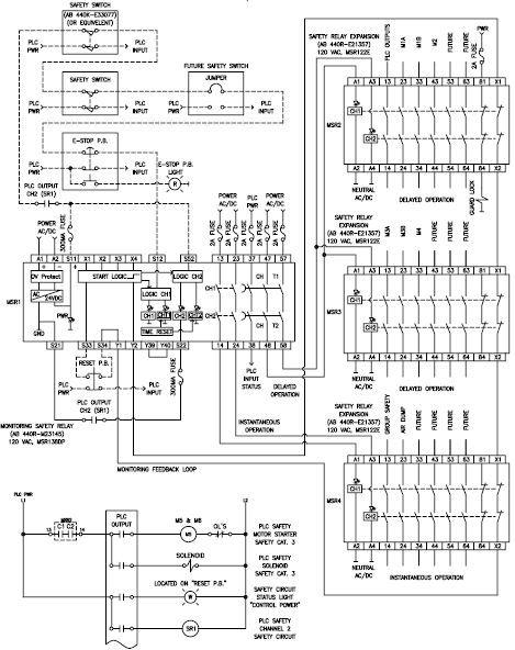
7 Safety CIS_303_Servo_Drive_Design_Guidelines_WHQ.doc, 0, October
8 Identification 7. Identification Label all motors at a permanent location near, but not on, the motor or gear reducer. Make sure the label contains motor tag number (refer to the equipment tagging guidelines), the common name (such as PRODUCT PUMP 3), and starter location. Label cabinets or enclosures that house contactors, starters, or other control devices on the outside with the source of the electrical power used. This might be the number of a specific MCC or a breaker number from a lighting distribution panel or general utility power panel. Label all major components (such as axis modules, motor starters, or local disconnects) as identified on the schematic diagrams. Identify all wires at each termination. Use wire markers to identify a unique number that corresponds to the schematic diagram. When the wires are part of a PLC system, label them with the same number as the input or output points of the PLC. CIS_303_Servo_Drive_Design_Guidelines_WHQ.doc, 0, October
9 Summaries 8. Summaries Enter information in these tables to track revisions to the master document. NOTE: In the Entry column, enter your information between the dashes. The entries automatically update matching document properties. Document Property Entry Master Owner Master Number -0- -Daniel Migliori- Increment revision numbers by one. Master Date -4/22/05- Number Date Owner Summary (Brief description of major changes) 0 4/22/2005 Daniel Migliori Original Development CIS_303_Servo_Drive_Design_Guidelines_WHQ.doc, 0, October
10 Summaries 8.1 Plant Customization Tracking Enter information in these tables to track revisions to plant customized documents. NOTE: In the Entry column, enter your information between the dashes. The entries automatically update document properties. Document Property Entry Plant Code -XXX- Plant Owner -Enter Name- Plant Number Plant Date -3/29/05- Use the following format for the Plant Number: <Master Number>.<Plant Number> Number Date Owner Summary (Brief description of major changes) 0 CIS_303_Servo_Drive_Design_Guidelines_WHQ.doc, 0, October
Kinetix 6000 Integrated Axis Modules
 Chapter 6 Kinetix 6000 Multi-axis Servo Drives Kinetix 6000 Integrated Axis Modules This section contains power specifications, mounting dimensions, and catalog numbers for the Bulletin 2094 (230V and
SECTION LOW VOLTAGE ACTIVE HARMONIC FILTER SYSTEM NEMA 1 ENCLOSED
 SECTION 16280 LOW VOLTAGE ACTIVE HARMONIC FILTER SYSTEM NEMA 1 ENCLOSED PART 1 - GENERAL 1.1 SUMMARY This specification defines the requirements for active harmonic filter systems in order to meet IEEE-519-2014
SECTION AUTOMATIC TRANSFER SWITCH
 SECTION 26 36 23 PART 1 - GENERAL 1.1 THE REQUIREMENT A. Furnish and install automatic transfer switches (ATS) with number of poles, amperage, voltage, withstand and close-on ratings as shown on the plans.
Servo Indexer Reference Guide
 Servo Indexer Reference Guide Generation 2 - Released 1/08 Table of Contents General Description...... 3 Installation...... 4 Getting Started (Quick Start)....... 5 Jog Functions..... 8 Home Utilities......
SERCOS and Analog Motion Configuration and Startup
 User Manual SERCOS and Analog Motion Configuration and Startup Catalog Numbers 1756-HYD02, 1756-M02AE, 1756-M02AS, 1756-M03SE, 1756-M08SE, 1756-M16SE, 1768-M04SE, 2094-SE02F-M00-S0, 2094-SE02F-M00-S1 Important
Tech Note #3: Setting up a Servo Axis For Closed Loop Position Control Application note by Tim McIntosh September 10, 2001
 Tech Note #3: Setting up a Servo Axis For Closed Loop Position Control Application note by Tim McIntosh September 10, 2001 Abstract: In this Tech Note a procedure for setting up a servo axis for closed
Allen-Bradley. Using the 1756-MO2AE with the TR Encoder (Cat. No ) Application Note
 Application Note") Allen-Bradley Using the 1756-MO2AE with the TR Encoder (Cat. No. 1756-2.9) Application Note Important User Information Because of the variety of uses for the products described in this publication, those
Allen-Bradley Using the 1756-MO2AE with the TR Encoder (Cat. No. 1756-2.9) Application Note Important User Information Because of the variety of uses for the products described in this publication, those
Kinetix 300 Drive (single-phase and three-phase) Power Specifications
 Power Specifications") Chapter 4 Kinetix 3 EtherNet/IP Indexing Servo Drives Kinetix 3 Drive (single-phase and three-phase) Power Specifications Attribute 297-V33PR1 297-V33PR3 297-V33PR5 297-V33PR6 AC input voltage AC input
Chapter 4 Kinetix 3 EtherNet/IP Indexing Servo Drives Kinetix 3 Drive (single-phase and three-phase) Power Specifications Attribute 297-V33PR1 297-V33PR3 297-V33PR5 297-V33PR6 AC input voltage AC input
Galil Motion Control. DMC 3x01x. Datasheet
 Galil Motion Control DMC 3x01x Datasheet 1-916-626-0101 Galil Motion Control 270 Technology Way, Rocklin, CA [Type here] [Type here] (US ONLY) 1-800-377-6329 [Type here] Product Description The DMC-3x01x
Job Sheet 2 Servo Control
 Job Sheet 2 Servo Control Electrical actuators are replacing hydraulic actuators in many industrial applications. Electric servomotors and linear actuators can perform many of the same physical displacement
D SERIES EM16 IP 20 / NEMA 1 & IP 66 / NEMA 4X COMPACT VECTOR CONTROL DRIVE EM 16 COMPACT VECTOR CONTROL DRIVE
 D SERIES EM16 IP 20 / NEMA 1 & IP 66 / NEMA 4X COMPACT VECTOR CONTROL DRIVE EM 16 COMPACT VECTOR CONTROL DRIVE 1 2 SERIES 1 2 pag. 4 pag. 5 Applications Model identification 3 pag. 5 4 pag. 6 Capacity
Soloist. Position Controller and Servo Amplifier PWM. Single axis digital servo controller with integral power supply and amplifier
 Soloist Position Controller and Servo Amplifier PWM Single axis digital servo controller with integral power supply and amplifier Advanced software architecture shortens customer development time; use
PREFACE ********************************************************** IT IS NOT INTENDED THAT THESE STANDARDS BE COPIED AND USED AS A SPECIFICATION!
 PREFACE This publication has been prepared as a guide for Architectural and Engineering (A&E) firms in the preparation of documents for the design and construction of new structures and the remodeling
Sigma 5 - Axis Servo Motor and Cables - Troubleshooting Guide
 LAST UPDATED: 09/24/2018 Electrical Safety Caution: When you do maintenance or repair on CNC machines and their components, you must always follow basic safety precaut and mechanical damage. Set the main
SRA 2250/6 RESISTOR ARS-01 RESISTOR AUTOMATICS
 ELECTRICAL ENGINEERING DIVISION Distribution Network Department SRA 2250/6 RESISTOR ARS-01 RESISTOR AUTOMATICS ELA T150.2 en SRA 2250/6 Resistor specification The SRA 2250/6 Resistor is intended to increase
AN-SERV-009. Luis Miranda 1
 THIS INFORMATION PROVIDED BY AUTOMATIONDIRECT.COM TECHNICAL SUPPORT IS SUPPLIED "AS IS", WITHOUT ANY GUARANTEE OF ANY KIND. These documents are provided by our technical support department to assist others.
Industrial Automation
 Software Development & Education Center Industrial Automation (HMI Drives Instrumentation Networking) Industrial Automation Automation is the use of machines, control systems and information technologies
NORTH HARRIS COUNTY REGIONAL WATER AUTHORITY. Section ELECTRICAL IDENTIFICATION
 PART 1 GENERAL 1.01 SUMMARY Section 16195 A. This Section includes electrical identification for the following: 1. Nameplates and labels 2. Wire and cable markers 3. Conduit markers 4. Cable tray markers
MicroManager. Torque Mode CTCW/Loadcell Control. Instruction Manual MM3000-CTCW
 MicroManager Torque Mode CTCW/Loadcell Control Instruction Manual MM3000-CTCW Table of Contents 1. General Description... 5 2. Specifications... 5 2.1 Electrical... 5 2.2 Physical... 6 3. Installation...
O A C I S. Open Architecture Control Integrated System. Common Faults List and Self-Check list for installation. Version 01.00
 O A C I S Open Architecture Control Integrated System Common Faults List and Self-Check list for installation Version 01.00 www.atainc.com ata@atainc.com All Rights Reserved 2 CONTENTS I. Common Faults
24V dc Analog Block I/O Module
 24V dc Analog Module Installation Mount the block I/O module in a vertical (recommended) or horizontal position. Allow sufficient room around the block for cooling air flow through the block module. Refer
Allen-Bradley. Using the 1756-MO2AE with the AEC (Cat. No ) Application Note
 Application Note") Allen-Bradley Using the 1756-MO2AE with the AEC (Cat. No. 4100-2.7) Application Note Important User Information Because of the variety of uses for the products described in this publication, those responsible
Allen-Bradley Using the 1756-MO2AE with the AEC (Cat. No. 4100-2.7) Application Note Important User Information Because of the variety of uses for the products described in this publication, those responsible
Self contained servo drive CLDP Technical data sheet
 voith.com Self contained servo drive CLDP Technical data sheet Advantages + + High energy efficiency + + High dynamics + + Oil free power pack and piping are not necessary + + Sensors used provide the
DC servo axis controller (Mammut) user s guide
 user s guide") DC servo axis controller (Mammut) user s guide What is Mammut? Mammut is CNCdrive s 2nd generation DC servomotor controller, it is the higher power and voltage version of Whale2 servo drive. In this documentation
DC servo axis controller (Mammut) user s guide What is Mammut? Mammut is CNCdrive s 2nd generation DC servomotor controller, it is the higher power and voltage version of Whale2 servo drive. In this documentation
TPM + power. Bosch Rexroth IndraDrive. Quick Startup Guide D Revision: 02
 4091-D021068 01 TPM + power Bosch Rexroth IndraDrive Quick Startup Guide 4091-D021074 Revision: 02 Quick Startup Guide TPM + power Revision history Revision Date Comment Chapter 01 08.07.2009 First release
The Allen-Bradley Servo Interface Module (Cat. No SF1) when used with the Micro Controller (Cat. No UC1) can control single axis
 when used with the Micro Controller (Cat. No UC1) can control single axis") Table of Contents The Allen-Bradley Servo Interface Module (Cat. No. 1771-SF1) when used with the Micro Controller (Cat. No. 1771-UC1) can control single axis positioning systems such as found in machine
Table of Contents The Allen-Bradley Servo Interface Module (Cat. No. 1771-SF1) when used with the Micro Controller (Cat. No. 1771-UC1) can control single axis positioning systems such as found in machine
Logosol AC/DC Programmable Servo & Logic Controller LS-151
 Features Motors supported - Panasonic A and S series motors - Yaskawa SGM and SGMM series - Brushless 60/120º commutated (AC) - Brush-commutated (DC) 12A peak, 8A continuous output current 18 to 91V motor
EPSITRON Electronic Circuit Breakers For Secondary Side DC Protection
 EPSITRON Electronic Circuit Breakers For Secondary Side DC Protection WHY SECONDARY-SIDE PROTECTION? Switched-mode power supplies provide secondary side DC voltage to control circuits and loads such as
INDEX. i 1. B Braking Resistor Dimensions: A 24 Braking Resistors: A 20 Braking Units: A 20. DURAPULSE AC Drive User Manual
 INDEX A AC Drive Cover: 1 6 Dimensions: 2 4 External Parts and Labels: 1 6 Heat Sink Fins: 1 6 Input Mode Switch (Sink/Source): 1 6 Introduction to DuraPulse GS3 AC drive: 1 3 Keypad: 1 6 Model Number
SAFETY AND HEALTH STANDARD ELECTRICAL GROUNDING Effective Date: 07/17/10 Standard: Document Number: KUCSH0039 Rev: 4
 SAFETY AND HEALTH STANDARD ELECTRICAL GROUNDING Effective Date: 07/17/10 Standard: 16.10 Document Number: KUCSH0039 Rev: 4 16.10.1 INTRODUCTION 16.10.1.1 The intent of this standard is to ensure that continuity
ESR. The Dynamic Solution. Applications. Products, Consultation, and Service. ESR Pollmeier GmbH
 Analog AC servo drive systems with sinusoidal commutation Servo drives in compact design, 230 V AC mains connection Servo motors with high power density up to 5.0 Nm / 1.1 kw Components of the TrioDrive
Integration of Linear Displacement Encoder and Servo Motor for 180 Ton Powder Compacting Press
 RESEARCH ARTICLE International Journal of Engineering and Techniques - Volume 4 Issue 1, Jan Feb 2018 Integration of Linear Displacement Encoder and Servo Motor for 180 Ton Powder Compacting Press V.Mahes
General-Purpose AC Servo. MELSERVO-JE Servo amplifier INSTRUCTION MANUAL (TROUBLE SHOOTING)
") General-Purpose AC Servo MELSERVO-JE Servo amplifier INSTRUCTION MANUAL (TROUBLE SHOOTING) F Safety Instructions Please read the instructions carefully before using the equipment. To use the equipment
General-Purpose AC Servo MELSERVO-JE Servo amplifier INSTRUCTION MANUAL (TROUBLE SHOOTING) F Safety Instructions Please read the instructions carefully before using the equipment. To use the equipment
SERCOS and Analog Motion Configuration and Startup
 User Manual SERCOS and Analog Motion Configuration and Startup 1756-HYD02, 1756-M02AE, 1756-M02AS, 1756-M03SE, 1756-M08SE, 1756-M16SE,1768-M04SE, 2094-SE02F-M00-S0, 2094-SE02F-M00-S1 Important user information
DC servo axis controller (Mammut) user s guide
 user s guide") DC servo axis controller (Mammut) user s guide What is Mammut? Mammut is CNCdrive s 2nd generation DC servomotor controller, it is the higher power and voltage version of Whale2 servo drive. In this documentation
DC servo axis controller (Mammut) user s guide What is Mammut? Mammut is CNCdrive s 2nd generation DC servomotor controller, it is the higher power and voltage version of Whale2 servo drive. In this documentation
O A C I S. Open Architecture Control Integrated System. Common Faults and Self-Check List for Installation. Version 01.01
 O A C I S Open Architecture Control Integrated System Common Faults and Self-Check List for Installation Version 01.01 www.atainc.com ata@atainc.com All Rights Reserved 2 CONTENTS I. COMMON FAULT LIST...
MicroManager. Velocity Mode PID Dancer/Loadcell Control. Instruction Manual MM3000-PID
 MicroManager Velocity Mode PID Dancer/Loadcell Control Instruction Manual MM3000-PID Table of Contents 1. General Description... 5 2. Specifications... 5 2.1 Electrical... 5 2.2 Physical... 6 3. Installation...
Power Processor - Series 700F 10KVA to 150KVA
 Power Processor - Series 700F 10KVA to 150KVA Power Conditioning and Regulation for Commercial & Industrial Equipment General Specifications PART 1 - GENERAL 1.1 DESCRIPTION This specification defines
Copyright 2014 YASKAWA ELECTRIC CORPORATION All rights reserved. No part of this publication may be reproduced, stored in a retrieval system, or
 Copyright 2014 YASKAWA ELECTRIC CORPORATION All rights reserved. No part of this publication may be reproduced, stored in a retrieval system, or transmitted, in any form, or by any means, mechanical, electronic,
2017 ELECTRICAL SAFETY SERVICES. Arc Flash Electrical Maintenance Lockout/Tagout And More
 2017 ELECTRICAL SAFETY SERVICES Arc Flash Electrical Maintenance Lockout/Tagout And More ABOUT LEWELLYN TECHNOLOGY Improving workplace safety since 1993 Daryn Lewellyn founded Lewellyn Technology more
Peak Current. Continuous Current. See Part Numbering Information on last page of datasheet for additional ordering options.
 Description Power Range The PWM servo drive is designed to drive brushless DC motors at a high switching frequency. A single red/green LED indicates operating status. The drive is fully protected against
Independent Technology Service Inc Independence Ave. Chatsworth, California Toll Free:
 Independent Technology Service Inc. 9182 Independence Ave. Chatsworth, California 91311 www.itscnc.com Toll Free: 1.800.342.3475 NEW Brush Amplifiers For Fadal Machines AMP-0006N-ITS AMP-0021N-ITS NEW
ELECTRICIAN S THEORY EXAMINATION 17 November 2012 QUESTION AND ANSWER BOOKLET
 Candidate Code No. ET43 For Board Use Only Result Date Int Result Date Int ELECTRICIAN S THEORY EXAMINATION 17 November 2012 QUESTION AND ANSWER BOOKLET INSTRUCTIONS READ CAREFULLY Time Allowed: Three
Ensemble HPe/CP/MP. Networked, Panel-Mount Drives PWM. Network drives through a high-speed serial interface to coordinate up to ten axes of motion
 Ensemble PWM Motion Controllers Ensemble HPe/CP/MP Networked, Panel-Mount Drives PWM Network drives through a high-speed serial interface to coordinate up to ten axes of motion Coordinate motion using
(VMC-1 Vertical Machining Center)
") (VMC-1 Vertical Machining Center) Machine Features & Specifications We are delighted to present the VMC-1 Machining Center. This machine comes standard with a 12-umbrella type automatic tool changer, full
(VMC-1 Vertical Machining Center) Machine Features & Specifications We are delighted to present the VMC-1 Machining Center. This machine comes standard with a 12-umbrella type automatic tool changer, full
Allen-Bradley. User Manual. Very High Speed Counter Module. (Cat. No VHSC) Allen-Bradley Spares
 Allen-Bradley Spares") 1 Allen-Bradley Very High Speed Counter Module User Manual (Cat. No. 1794-VHSC) Allen-Bradley Spares Important User Information Because of the variety of uses for the products described in this publication,
1 Allen-Bradley Very High Speed Counter Module User Manual (Cat. No. 1794-VHSC) Allen-Bradley Spares Important User Information Because of the variety of uses for the products described in this publication,
Kinetix 300 and Kinetix 350 EtherNet/IP Servo Drives
 Kinetix 300 and Kinetix 350 EtherNet/IP Servo Drives The Kinetix 300 EtherNet/IP indexing drive provides a cost-effective single-axis solution for low axis-count motion control applications. By using one
General-Purpose AC Servo. MELSERVO-JE Servo amplifier INSTRUCTION MANUAL (TROUBLE SHOOTING)
") General-Purpose AC Servo MELSERVO-JE Servo amplifier INSTRUCTION MANUAL (TROUBLE SHOOTING) B Safety Instructions Please read the instructions carefully before using the equipment. To use the equipment
General-Purpose AC Servo MELSERVO-JE Servo amplifier INSTRUCTION MANUAL (TROUBLE SHOOTING) B Safety Instructions Please read the instructions carefully before using the equipment. To use the equipment
ELECTRICAL GENERAL DESIGN AND CONSTRUCTION STANDARD PART 1: GENERAL Electrical/Telecommunications Design
 PART 1: GENERAL 1.01 Electrical/Telecommunications Design A. This section of the design and construction standard outlines general requirements for electrical and telecommunications designs to be performed
2. Electrical rooms shall be centrally located and stacked so that feeder conduits and bus duct are run as straight and short as possible.
 PART 1: GENERAL 1.01 Electrical/Telecommunications Design A. This section of the design and construction standard outlines general requirements for electrical and telecommunications designs to be performed
General-Purpose AC Servo. MELSERVO-JE Servo amplifier INSTRUCTION MANUAL (TROUBLE SHOOTING)
") General-Purpose AC Servo MELSERVO-JE Servo amplifier INSTRUCTION MANUAL (TROUBLE SHOOTING) D Safety Instructions Please read the instructions carefully before using the equipment. To use the equipment
General-Purpose AC Servo MELSERVO-JE Servo amplifier INSTRUCTION MANUAL (TROUBLE SHOOTING) D Safety Instructions Please read the instructions carefully before using the equipment. To use the equipment
Section 16621A - AUTOMATIC TRANSFER SWITCH. Part 1 General
 Section 16621A - AUTOMATIC TRANSFER SWITCH Part 1 General 1.01 One 600 Amp, 3 Phase, 480 Volt Automatic Transfer Switch (ATS) shall be provided with gasketed enclosure. The ATS shall consist of an inherently
2.017 DESIGN OF ELECTROMECHANICAL ROBOTIC SYSTEMS Fall 2009 Lab 4: Motor Control. October 5, 2009 Dr. Harrison H. Chin
 2.017 DESIGN OF ELECTROMECHANICAL ROBOTIC SYSTEMS Fall 2009 Lab 4: Motor Control October 5, 2009 Dr. Harrison H. Chin Formal Labs 1. Microcontrollers Introduction to microcontrollers Arduino microcontroller
Servo Amplifier - Troubleshooting Guide
 Haas Technical Documentation Servo Amplifier - Troubleshooting Guide Scan code to get the latest version of this document Translation Available There are four versions of Haas amplifiers. 30A [1], 45A
Analog Servo Drive BD15A8
 Description Power Range The BD15A8 PWM servo drive is designed to drive brushless DC motors at a high switching frequency. t is fully protected against over-voltage, over-current, over-heating and short-circuits.
Committed to Premium Quality. AC Servo System Catalog
 Committed to Premium Quality AC Servo System Catalog Company Profile CONTENTS DB100 Series AC Servo System 03 Application fields 04 Servo Driver Product Description 05 Servo Motor Product Description 07
SECTION IDENTIFICATION FOR ELECTRONIC SAFETY AND SECURITY
 SECTION 280553-IDENTIFICATION FOR ELECTRONIC SAFETY AND SECURITY PART 1 - GENERAL 1.1 DESCRIPTION A. This specification section covers the furnishing and installation of nameplates, labels, wire markers,
Analog Servo Drive 20A20
 Description Power Range NOTE: This product has been replaced by the AxCent family of servo drives. Please visit our website at www.a-m-c.com or contact us for replacement model information and retrofit
8510 AC Spindle Drive System
 8510 AC Spindle Drive System Manual Important User Information Solid state equipment has operational characteristics differing from those of electromechanical equipment. Safety Guidelines for the Application,
Field Service Procedure PCU Kit, XX97, XX97A & XX00
 1. Brief Summary: Troubleshooting document for diagnosing a fault with and replacing the PCU assembly on the XX97, XX97A and XX00 series antennas. 2. Checklist: Verify Initialization N0 Parameter Pedestal
First Draft Language
 110.16 First Draft Language (B) Service Equipment. In addition to the requirements in (A), service equipment shall contain the following information: (1) Nominal system voltage (2) Arc flash boundary (3)
All Servos are NOT Created Equal
 All Servos are NOT Created Equal Important Features that you Cannot Afford to Ignore when Comparing Servos Michael Miller and Jerry Tyson, Regional Motion Engineering Yaskawa America, Inc. There is a common
BLuAC5 Brushless Universal Servo Amplifier
 BLuAC5 Brushless Universal Servo Amplifier Description The BLu Series servo drives provide compact, reliable solutions for a wide range of motion applications in a variety of industries. BLu Series drives
1) Press the Connect button to establish communication with NS300 or NS500.
 Press the Connect button to establish communication with NS300 or NS500.") ENGINEERING PUBLICATION MOTION CONTROL DIVISION PRODUCT:NSXXX CATEGORY: TECH NOTE ENGINEER: Chris Knudsen SUBJECT: NSXXX EXAMPLE CONFIGURATION DISTRIBUTION: MCD NSxxx Configuration Guide NSxxx software
ENGINEERING PUBLICATION MOTION CONTROL DIVISION PRODUCT:NSXXX CATEGORY: TECH NOTE ENGINEER: Chris Knudsen SUBJECT: NSXXX EXAMPLE CONFIGURATION DISTRIBUTION: MCD NSxxx Configuration Guide NSxxx software
What is VC-VH? Old capacitor voltage terminology. Terminals on capacitor
 What is VC-VH? Old capacitor voltage terminology Terminals on capacitor VC=Voltage common; VH= voltage hermetic 2-Stage Board Voltage constantly monitored at compressor run capacitor. Looks for voltage
Application Note: CBLIO-ISO1-xM Cables for the Class 5 D-Style SmartMotor, Revised: 11/9/2016.
 Copyright Notice 2016, Moog Inc., Animatics. Application Note: CBLIO-ISO1-xM Cables for the Class 5 D-Style SmartMotor,. This document, as well as the software described in it, is furnished under license
NC Joining Module NCFH
 NC Joining System NC Joining Module NCFH 1... 60 kn with Hollow Shaft Motor Type 2151B... The NC joining module Type 2151B... (in two sizes) with integrated piezoelectric force sensor for nominal forces
This section applies to the requirements for the performance of power system studies by both the Design Engineer and the Contractor.
 Basis of Design This section applies to the requirements for the performance of power system studies by both the Design Engineer and the Contractor. Background Information A Short Circuit and Coordination
AN EXAMPLE OF A STANDARD ARC FLASH PPE LABELING STRATEGY
 The Electrical Power Engineers Qual-Tech Engineers, Inc. 201 Johnson Road Building #1 Suite 203 Houston, PA 15342-1300 Phone 724-873-9275 Fax 724-873-8910 www.qualtecheng.com AN EXAMPLE OF A STANDARD ARC
INDUSTRIAL AUTOMATION OVERVIEW S700
 INDUSTRIAL AUTOMATION OVERVIEW S700 1 2 Your Benefits Advantage Why S300 S700 Increased throughput Reduced part # Smaller switchgear cabinets Esay to use High performances allow to get a reduced settling
2014 NEC Changes Part 1
 www.garyklinka.com Page 1 of 8 Instructions: Fee $20 1. Print these pages. 2. Circle the correct answers and transfer them to the answer sheet. 3. Page down to the last page for the verification forms
IPS INTELLIGENT PUMP STARTER. Integrated Tru-power electronic motor and pump protection
 IPS INTELLIGENT PUMP STARTER With TM Smartstart Ø & Ø, 0/60 Hz, 20~600 VAC, /~00HP Integrated electronic pump protection overload Power metering and data logging options Motor Protection Key dealer yr.
INCLINED PLANE RIG LABORATORY USER GUIDE VERSION 1.3
 INCLINED PLANE RIG LABORATORY USER GUIDE VERSION 1.3 Labshare 2011 Table of Contents 1 Introduction... 3 1.1 Remote Laboratories... 3 1.2 Inclined Plane - The Rig Apparatus... 3 1.2.1 Block Masses & Inclining
Exercise 6. Range and Angle Tracking Performance (Radar-Dependent Errors) EXERCISE OBJECTIVE
 EXERCISE OBJECTIVE") Exercise 6 Range and Angle Tracking Performance EXERCISE OBJECTIVE When you have completed this exercise, you will be familiar with the radardependent sources of error which limit range and angle tracking
Exercise 6 Range and Angle Tracking Performance EXERCISE OBJECTIVE When you have completed this exercise, you will be familiar with the radardependent sources of error which limit range and angle tracking
Data Acquisition Modules/ Distributed IO Modules
 User Manual Data Acquisition Modules/ Distributed IO Modules Future Design Controls, Inc. 7524 West 98 th Place / P.O. Box 1196 Bridgeview, IL 60455 888.751.5444 - Office: 888.307.8014 - Fax 866.342.5332
NC Joining Module NCFH
 NC Joining System NC Joining Module NCFH with Hollow Shaft Motor and Compact Design The NC joining module (in two sizes) with integrated piezoelectric force sensor for nominal forces of 1... 60 kn is excellent
Top-Innovator EncoderAnalyzer. For testing encoders. Made in Germany Expect more. Winding testers
 Top-Innovator 2014 EncoderAnalyzer For testing encoders Made in Germany Expect more. Winding testers The EncoderAnalyzer Complicated applications made easy! The EncoderAnalyzer is THE tester for checking
Engineering Specifications Mansfield Unit 3 Project Number: CONFIDENTIAL REVISION TABLE ~JW. Prepared. Bo6 Lilly. w;.
 Digital Governor/ Unit Control Turbine Controls REVISION TABLE Rei 0 1 Date 11/30/2015 1/6/2016 Purpose Bidding Bidding ~JW Prepared Bo6 Lilly w;. Bob Lilly Reviewed -B\U^M^ Bill Yates ^\J^^l^^ Bill Yates
SRV02-Series. Rotary Servo Plant. User Manual
 SRV02-Series Rotary Servo Plant User Manual SRV02-(E;EHR)(T) Rotary Servo Plant User Manual 1. Description The plant consists of a DC motor in a solid aluminum frame. The motor is equipped with a gearbox.
9 Things to Consider When Specifying Servo Motors
 9 Things to Consider When Specifying Servo Motors Ensuring Optimal Servo System Performance for your Application Michael Miller and Jerry Tyson, Regional Motion Engineering Yaskawa America, Inc. There
A. Product Data: For each electrical identification product indicated.
 SECTION 16075 - ELECTRICAL IDENTIFICATION PART 1 - GENERAL 1.1 RELATED DOCUMENTS A. Drawings and general provisions of the Contract, including General and Supplementary Conditions and Division 1 Specification
4. Special Systems Design: including Fire Alarm and Security. C. Electrical and Telecommunications Ductbanks: Refer to Section 16118
 PART 1: GENERAL This section of the design standard outlines general requirements for electrical and telecommunications designs to be performed for the University of Texas at Austin. This standard is intended
BLuAC5 Brushless Universal Servo Amplifier
 BLuAC5 Brushless Universal Servo Amplifier Description The BLu Series servo drives provide compact, reliable solutions for a wide range of motion applications in a variety of industries. BLu Series drives
How to Configure IFOV. Revision: 1.01
 How to Configure IFOV Revision: 1.01 Global Technical Support Go to www.aerotech.com/global-technical-support for information and support about your Aerotech products. The website provides downloadable
Inverter Drive /Vector Drive Motors & Controls
 H2 Inverter/ Encoderless Vector Inverter Drive /Vector Drive & Controls 3/4 thru 50 180-264 VAC 3 Phase - 50/60 Hz 3/4 thru 60 340-528 VAC 3 Phase - 50/60 Hz 3/4 thru 60 515-660 VAC 3 Phase - 60 Hz HVAC
GE 320: Introduction to Control Systems
 GE 320: Introduction to Control Systems Laboratory Section Manual 1 Welcome to GE 320.. 1 www.softbankrobotics.com 1 1 Introduction This section summarizes the course content and outlines the general procedure
NEMA Contactor and Starter Specifications
 Technical Data NEMA Contactor and Starter Specifications Bulletins 00, 0, 0, 0, 06, 06X, 07, 07X, 09,,, E/F/G, E/F/G Topic Page Specifications Electrical Ratings Mechanical Ratings, Construction, Environmental
Bulletin 509 Three Phase Full Voltage NEMA Starters Size 9 Series A. Renewal Parts
 Bulletin 509 Three Phase Full Voltage NEMA Starters Size 9 Series A Renewal Parts Warning: To avoid hazards of electrical shock, remove all power before proceeding. Auxiliary contacts commonly control
PHOENIX, ARIZONA SITE SURVEY REPORT. PROVEN SOLUTIONS THAT DRIVE EFFICIENCY AND PRODUCTIVITY IN YOUR SUPPLY CHAIN
 AB&R (American Barcode and RFID) 3431 E Elwood St, Phoenix AZ 85040 Phone: (602) 651-1600 Fax: (602) 651-1611 Website: Contact: solutions@abr.com SITE SURVEY REPORT PHOENIX, ARIZONA Prepared By: Curt Squires
Introduction to PLC and Ladder Logic Programming
 Introduction Introduction to PLC and Ladder Logic Programming A PLC (Programmable Logic Controller) is an industrial computer used for automation of electromechanical processes, such as control of machinery
MECKLENBURG COUNTY. Land Use and Environmental Service Agency Code Enforcement 9/8/10 ELECTRICAL CONSISTENCY MEETING. Code Consistency Questions
 conduit? 9/8/10 ELECTRICAL CONSISTENCY MEETING Code Consistency Questions 1. Can branch circuits of different services be installed in the same Yes, see 300.3(C)(1) for conductors of different systems
XC4e PWM Digital Drive
 PWM Digital Drive HyperWire fiber-optic interface Up to 30 A peak output current Integral power supply Amplifiers/Drives Drive brush, brushless, voice coil, or stepper motors Safe torque off (STO) safety
Michigan State University Construction Standards SWITCHBOARDS, PANELBOARDS, AND CONTROL CENTERS PAGE
 PAGE 262400-1 SECTION 262400 PART 1 - GENERAL 1.1 RELATED DOCUMENTS A. Drawings and general provisions of the Contract, including General and Supplementary Conditions and Division 01 Specification Sections,
Electromechanical. NC Joining Systems. Flexible Solutions for Your Application
 Electromechanical NC Joining Systems Flexible Solutions for Your Application Electromechanical NC Joining Systems For joining and press-fit applications, electromechanical NC joining systems are increasingly
XARS8D18p / XARS12D18p / XARS8L12p Quick Start Guide
 Quick Start Guide Harmony www.schneiderelectric.com www.schneiderelectric.com/control TM XARS8D18W / XARS8D18H / XARS12D18W / XARS12D18H exlhoist XARS8L12W / XARS8L12H DANGER HAZARD OF ELECTRIC SHOCK,
1. This Section specifies the ethernet Category 5E data cabling system for buildings and structures.
 PAGE 271200-1 SECTION 271200 PART 1 - GENERAL 1.1 RELATED DOCUMENTS A. Drawings and general provisions of the Contract, including General and Supplementary Conditions and Division 01 Specification Sections,
Combination Generator Control Module
 User Manual Combination Generator Control Module Catalog Numbers 1407-CGCM Important User Information Read this document and the documents listed in the additional resources section about installation,
Analog Servo Drive. Peak Current 16 A (11.3 A RMS )
") Description The PWM servo drive is designed to drive three phase brushless motors with sine wave current at a high switching frequency. The drive requires two sinusoidal command signals with a 120-degree
Description The PWM servo drive is designed to drive three phase brushless motors with sine wave current at a high switching frequency. The drive requires two sinusoidal command signals with a 120-degree
NEWPCC VARIABLE FREQUENCY DRIVES Section LAB RENOVATION BID OPPORTUNITY NO PAGE 1 OF SCOPE
 BID OPPORTUNITY NO. 253-2011 PAGE 1 OF 8 PART 1 GENERAL 1.1 SCOPE.1 This specification shall apply to the materials, design, fabrication, inspection, and testing of 600 V Variable Frequency Drives (VFD)