Ex instruction manual. Rotamass Coriolis mass flow meter ATEX. IM 01U10X01-00EN-R_002, 2nd edition,
|
|
|
- Morgan Quinn
- 6 years ago
- Views:
Transcription

1 Ex instruction manual Rotamass Coriolis mass flow meter ATEX IM 01U10X01-00EN-R_002, 2nd edition,
2 Table of contents Table of contents 1 Language variants of ATEX documentation Introduction Scope of application Applicable documents Explanation Nameplates Sensor, integral type Transmitter, integral type Sensor, remote type Transmitter, remote type Ordering information MS code Installation General installation rules Threads for cable glands Ex d-relevant transmitter threads Electrical installation General rules Grounding connections and intrinsically safe circuits Transmitter connection terminals Configuration of input/output terminals for HART communication and Foundation Fieldbus Configuration of input/output terminals for Modbus communication Installation diagrams Integral type without intrinsically safe I/O outputs Integral type with intrinsically safe I/O outputs Integral type for Foundation Fieldbus communication (intrinsically safe) Remote type without intrinsically safe I/O outputs Remote type with intrinsically safe I/O outputs Remote type for Foundation Fieldbus communication (intrinsically safe) Operation, maintenance and repair General rules Replacing the sensor Replacing the transmitter Approvals and standards Technical data Integral type Remote type Nano, CNG, LPG sensor Supreme, CNG, LPG, Intense and Giga sensor Prime and Hygienic sensor Transmitter Connecting cable / 62 IM 01U10X01-00EN-R_002, 2nd edition,
3 Table of contents Connection to Rotamass 3 sensor Ex code Determining the maximum temperatures based on the Ex code specification by temperature es Identification via MS code Identification via MS code and Ex code Rotamass Nano, CNG, LPG Rotamass Supreme, CNG, LPG and Intense Rotamass Giga Rotamass Prime and Hygienic IM 01U10X01-00EN-R_002, 2nd edition, / 62
4 ATEX Language variants of ATEX documentation 1 Language variants of ATEX documentation This is only applicable to the countries in the European Union. GB SK CZ DK I LT E LV EST NL PL SF SLO P H F BG D RO S M GR 4 / 62 IM 01U10X01-00EN-R_002, 2nd edition,
5 Scope of application ATEX Introduction 2 Introduction 2.1 Scope of application These instructions apply to the following Rotamass Total Insight (TI) product families: Rotamass Nano Rotamass Supreme Rotamass Giga Rotamass Prime Rotamass Intense Rotamass Hygienic Rotamass CNG Rotamass LPG Rotamass TI transmitter in combination with a Rotamass 3 sensor 2.2 Applicable documents The following documents are part of these instructions: Quick reference guide Operating instructions Software user instructions General specification 2.3 Explanation is used as a Placeholder for a single character. IM 01U10X01-00EN-R_002, 2nd edition, / 62
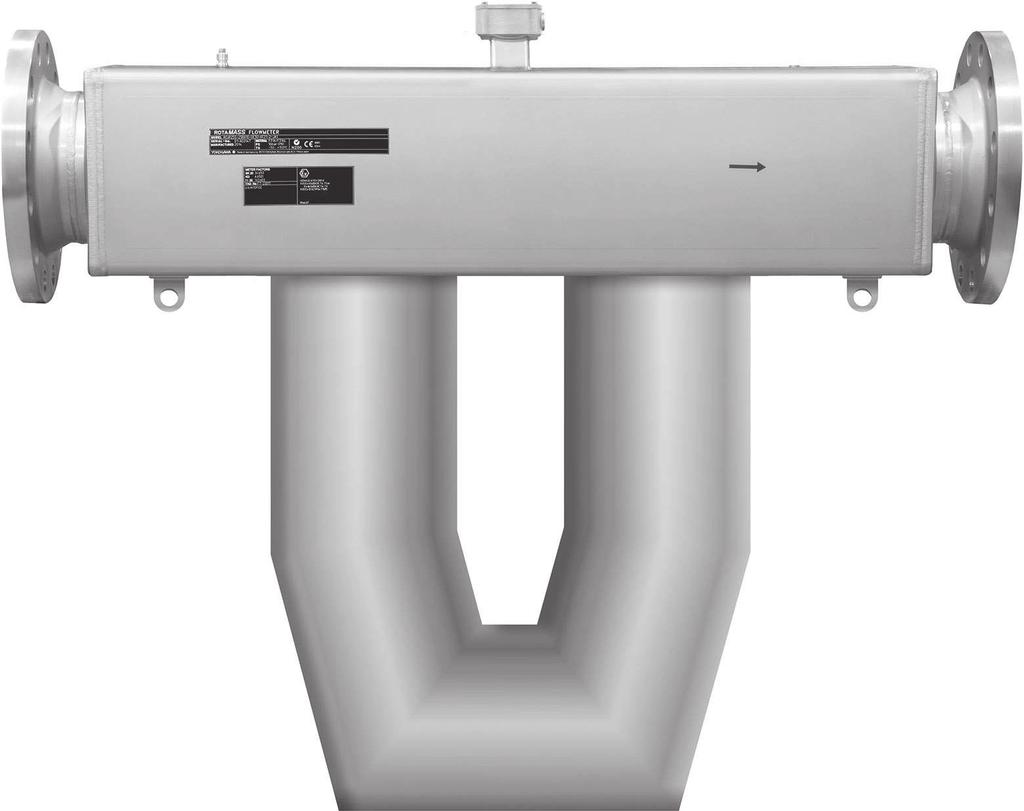
6 ATEX Nameplates Sensor, integral type 3 Nameplates The sensor as well as the transmitter each contain a main nameplate and an additional nameplate that feature different information. The variants of the nameplates are described below. 3.1 Sensor, integral type Main nameplate ES34S-50BD40-OE90-KF21-4-JA / bar 60bar 3 8 o C 150 o C 4 i MS code 2 Serial number 3 Year of manufacture 4 Ambient temperature range 5 Material wetted parts 6 Flow direction 7 Reference to documentation 8 Approvals, identifications, test and quality seals 9 Manufacturer's address 10 Notified body for ATEX QA supervision 11 Test pressure 12 Maximum allowed working pressure at room temperature 13 Maximum allowed process temperature 6 / 62 IM 01U10X01-00EN-R_002, 2nd edition,
7 Sensor, integral type ATEX Nameplates Additional nameplate MHzxkg/h 16.8 kg/l 144 HZ Ex db ib IIC T6...T1 Gb or 2 6 data for custody transfer II 2 G II 2 D FISCO Fieldbus Device DEKRA 15ATEX0023X Ex db e ib IIC T6...T1 Gb Ex ib tb IIIC T150 o C Db ENCLOSURE IP66/IP67 Um: 250V a.p6.p5.p4.p4.p2 SEE CERTIFICATE FOR DATA i Calibration constants of sensor 2 Customer-specific identification 3 Identification field for use according to Ex db or Ex db e 4 ATEX identification 5 Reference to documentation 6 Identification of type of protection, explosion group, temperature es and equipment protection level 7 Maximum r.m.s. a.c. or d.c. voltage 8 Ex code 9 IP code IM 01U10X01-00EN-R_002, 2nd edition, / 62
8 ATEX Nameplates Transmitter, integral type 3.2 Transmitter, integral type Main nameplate ES34S-50BD40-OE90-KF21-4-JA i VAC or VAC, 50/60Hz 24VDC or VDC; 10W o C MS code 2 Serial number 3 Year of manufacture 4 Power supply range 5 Ambient temperature range 6 Reference to documentation 7 Approvals, identifications, test and quality seals 8 Notified body for ATEX QA supervision 9 Manufacturer's address Additional nameplate 1 2 II 2 G II 2 D DEKRA 15ATEX0023X Ex db ib IIC T6...T1 Gb or Ex db e ib IIC T6...T1 Gb Ex ib tb IIIC T150 o C Db SEE CERTIFICATE FOR DATA ENCLOSURE IP66/IP67 Um: 250V FISCO Fieldbus Device i Identification field for use according to Ex db or Ex db e 2 ATEX identification 3 Reference to documentation 4 Identification of type of protection, explosion group, temperature es and equipment protection level 5 Maximum r.m.s. a.c. or d.c. voltage 6 IP code 8 / 62 IM 01U10X01-00EN-R_002, 2nd edition,
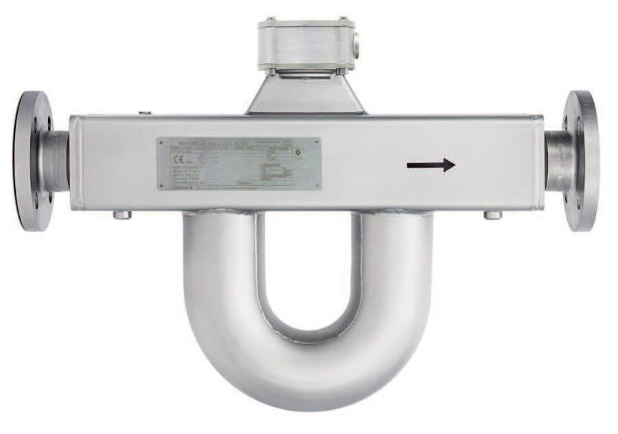
9 Sensor, remote type ATEX Nameplates 3.3 Sensor, remote type Main nameplate ES34S-50BD40-OE90-KF21-4-JA / bar 60bar 3 8 o C 150 o C 4 i MS code 2 Serial number 3 Year of manufacture 4 Ambient temperature range 5 Material wetted parts 6 Flow direction 7 Reference to documentation 8 Approvals, identifications, test and quality seals 9 Manufacturer's address 10 Notified body for ATEX QA supervision 11 Test pressure 12 Maximum allowed working pressure at room temperature 13 Maximum allowed process temperature Additional nameplate MHzxkg/h 16.8 kg/l 144 HZ 2 Ex ib IIC T6...T1 Gb or 5 a.p6.p5.p4.p4.p2 SEE CERTIFICATE FOR DATA IP66/67 II 2 G II 2 D DEKRA 15ATEX0023X Ex ib IIIC T150 o C Db FISCO Fieldbus Device 1 Calibration constants of sensor 2 Customer-specific identification 3 ATEX identification 4 Reference to documentation 5 Identification of type of protection, explosion group, temperature es and equipment protection level 6 Ex code 7 IP code i 6 7 IM 01U10X01-00EN-R_002, 2nd edition, / 62
10 ATEX Nameplates Transmitter, remote type 3.4 Transmitter, remote type Main nameplate ES34S-50BD40-OE90-KF21-4-JA i VAC or VAC, 50/60Hz 24VDC or VDC; 10W o C MS code 2 Serial number 3 Year of manufacture 4 Power supply range 5 Ambient temperature range 6 Reference to documentation 7 Approvals, identifications, test and quality seals 8 Notified body for ATEX QA supervision 9 Manufacturer's address Additional nameplate 1 i FISCO Fieldbus Device Identification field for use according to Ex db or Ex db e 2 ATEX identification 3 FISCO marking (only present for devices with Fieldbus communication) 4 Reference to documentation 5 Identification of type of protection, explosion group, temperature es and equipment protection level 6 Maximum r.m.s. a.c. or d.c. voltage 7 IP code 10 / 62 IM 01U10X01-00EN-R_002, 2nd edition,
11 MS code ATEX Ordering information 4 Ordering information 4.1 MS code The MS code of the Rotamass TI is explained below. Items 1 through 14 are mandatory entries and must be specified at the time of ordering. Device options (item 15) can be selected and specified individually by separating them with slashes. 1. Transmitter 2. Sensor 3. Meter size 4. Material wetted parts 5. Process connection size 6. Process connection type 7. Sensor housing material 8. Medium temperature range 9. Mass flow and density accuracy 10. Design and housing 11. Ex approval 12. Cable entries 13. Communication type and I/O 14. Display 15. Options Details are available in the general Specifications of the corresponding Rotamass series. IM 01U10X01-00EN-R_002, 2nd edition, / 62
12 ATEX Installation General installation rules 5 Installation 5.1 General installation rules DANGER Explosion hazard from electrostatic discharge or brush discharge Life-threatening injuries or ignition of explosive atmospheres Avoid actions that could lead to electrostatic discharges. For example, do not wipe the coated surface of the transmitter using a piece of cloth. Install the device in zone 1 or 21 so as to avoid the risk of electrostatic discharges and brush discharges caused by rapid dust flow. Modifying the coriolis mass flow meter as well as using unauthorized parts is prohibited and will void the certification. Only trained personnel may install and operate the device in an industrial environment. The instructions have to be read and understood by all persons authorized with the transport, storage, installation, electrical installation, commissioning, operation, maintenance and disposal of the Coriolis mass flow meter in hazardous areas. The respective applicable national safety regulations concerning the installation of the Coriolis mass flow meter in hazardous areas must be followed. Only media to which the wetted parts are sufficiently resistant may be used. The use of suitable cable glands must be ensured, see Threads for cable glands [} 13]. Ambient and medium temperature must not exceed the respective maximum values for the applicable specification by temperature es [} 46]. The integral type and the remote-type transmitter must not be insulated. 12 / 62 IM 01U10X01-00EN-R_002, 2nd edition,
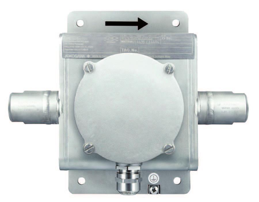
13 Threads for cable glands ATEX Installation 5.2 Threads for cable glands The terminal box in the transmitter for connecting the sensor is certified as Ex i. IP66/67- certified cable glands and blind plugs must be used for this connection. At a minimum, the allowable temperature range for cable glands and blind plugs must extend from C. Blind plugs for redundant bushings and cable glands are factory-installed. The housing of the transmitter is designed as type of protection Ex db. Optionally, the terminal box for the power supply and the inputs/outputs is also certified as Ex e. Properly certified cable glands and blind plugs must be used for this purpose. At a minimum, the allowable temperature range for cable glands and blind plugs must extend from C. The type of protection is to be indicated on the nameplate's identification fields, see Nameplates [} 6]. If the device is to be operated without communication lines, the cable gland provided must be replaced by a blind plug of the same ification M/N/W 4 5 Fig. 1: Threads for the cable glands of the transmitter Thread position, see the following table M Marking of thread size: ISO M N or W Marking of thread size: ANSI 1/2" NPT The following figure shows the relevant position of the IM 01U10X01-00EN-R_002, 2nd edition, / 62
14 ATEX Installation Threads for cable glands Thread MS code Position 12 ISO M ANSI 1/2" NPT 2 Thread position Delivery state Integral type Blind plug IP66/67, factoryinstalled Blind plug IP66/67, factoryinstalled Remote type Metal cable gland IP66/67, factoryinstalled Blind plug IP66/67, factoryinstalled Cable gland Ex e tb IP66/67, factoryadded Blind plug Ex e ta IP66/67, factory-installed Cable gland Ex e tb IP66/67, factoryadded Blind plug IP66/67, factoryinstalled Blind plug IP66/67, factoryinstalled Metal cable gland IP66/67, factoryinstalled Blind plug IP66/67, factoryinstalled Blind plug Ex db e ta IP66/67, factory-installed Notes A properly certified IP66/67 cable gland must be provided and professionally installed by the user for type of protection Ex db. A properly certified IP66/67 blind plug must be provided and professionally installed by the user for type of protection Ex db. A properly certified IP66/67 cable gland must be provided and professionally installed by the user for type of protection Ex db. Depending on the type of protection used Ex e, Ex db, Ex tb properly certified cable glands with IP66/67 must be provided and professionally installed by the user. Depending on the type of protection used Ex e, Ex db, Ex tb properly certified cable glands with IP66/67 must be provided and professionally installed by the user. The cable gland on the sensor is factory-installed. At a minimum, the allowable cable gland temperature must include the range from C for option L and the range C for option Y. 14 / 62 IM 01U10X01-00EN-R_002, 2nd edition,
15 Ex d-relevant transmitter threads ATEX Installation 5.3 Ex d-relevant transmitter threads Ex-certified models are equipped with an Ex d transmitter housing Fig. 2: Ex d-relevant transmitter threads 1 Thread for display cover 2 Threads for cable glands 3 Thread for back cover Technical data of Ex d-relevant threads Thread Display cover 2 Back cover 2 Cable glands Lead in mm Tolerance field Threads in engagement in mm Minimum screw-in depth in mm 6g/6H 8 16 ISO M H ANSI 1/2" NPT acc. to ANSI B IM 01U10X01-00EN-R_002, 2nd edition, / 62
16 ATEX Electrical installation General rules 6 Electrical installation 6.1 General rules DANGER Insufficient connection to the potential equalization system Life-threatening injuries from electric shock or ignition of explosive atmospheres Connect remote-type sensor via the grounding terminal outside of the housing to the potential equalization system, see Grounding connections and intrinsically safe circuits [} 17]. Connect transmitter to the potential equalization system via the grounding terminal outside of the housing, see Grounding connections and intrinsically safe circuits [} 17]. Connect grounding cable of power supply cable to the grounding screw in the terminal box, see Grounding connections and intrinsically safe circuits [} 17]. The relevant national standards must be considered for the electrical installation. Rotamass must be integrated into the potential equalization system of the hazardous area. The potential equalization must be ensured alongside the intrinsically safe circuit. The power supply must be established with a voltage 250 V at the terminals L/+ and N/-. The grounding screw in the terminal box must be mechanically firmly connected with the threaded hole. If the type of protection Ex e is used, cable cross sections of 0.8 to 2.5 mm 2 must be used for the cables of the power supply and the cables of the inputs/outputs. The insulation of the cores must be stripped off 5 to 6 mm. The cable connections for the inputs/outputs must be established according to the connection tables [} 18]. In the process, it must be ensured that the connection type matches the corresponding position of the MS code on the nameplate. The maximum input parameters of the intrinsically safe outputs must not be exceeded. 16 / 62 IM 01U10X01-00EN-R_002, 2nd edition,
17 COM TP3 TP2 TP1 S2 - S2 + S1 - S1 + Grounding connections and intrinsically safe circuits ATEX Electrical installation 6.2 Grounding connections and intrinsically safe circuits Fig. 3: Grounding connections on transmitter and sensor 1 Grounding screw in terminal box for grounding conductor 2 Grounding terminal on transmitter for potential equalization 3 Grounding terminal on sensor for potential equalization D - D + D + D - S1 + S1 - S2 + S2 - TP1 TP2 TP Fig. 4: Connection terminal circuits (transmitter on the left side, sensor on the right side) 1 Driver circuit 4 Signal grounding 2 Sensor circuits 5 Transmitter 3 measurement circuits 6 Sensor IM 01U10X01-00EN-R_002, 2nd edition, / 62
18 ATEX Electrical installation Transmitter connection terminals 6.3 Transmitter connection terminals Configuration of input/output terminals for HART communication and Foundation Fieldbus Fig. 5: Terminal box for connection to external devices for HART and for the transmitter power supply 1 Power supply connection terminals 5 I/O2 +/- 2 Grounding screw in terminal box 6 I/O3 +/- 3 Grounding terminal 7 I/O4 +/- 4 I/O1 +/- 8 WP The applicable operating instructions must be observed for connecting the cables. The connection type is defined according to the product variant ordered. The following figure shows the relevant position of the MS code Position 13 JA JB JC JD Connection terminal assignment I/O1 +/- I/O2 +/- I/O3 +/- I/O4 +/- WP Iout1 P/Sout1 Active Write-protect Iout1 P/Sout1 P/Sout2 Iout2 Active Active Write-protect Iout1 P/Sout1 Iout2 Sin Active Active Write-protect Iout1 P/Sout1 Sout P/Sout2 Active Write-protect 18 / 62 IM 01U10X01-00EN-R_002, 2nd edition,
19 Transmitter connection terminals ATEX Electrical installation MS code Position 13 JE JF JG JH JJ JK JL JM JN JP JQ JR JS F Connection terminal assignment I/O1 +/- I/O2 +/- I/O3 +/- I/O4 +/- WP Iout1 Active Iout1 Active Iout1 Active Iout1 Active Iout1 Active Iout1 Active Iout1 Active Iout1 Active Iout1 Active Iout1 Iout1 Iout1 Iout1 Foundation Fieldbus P/Sout1 P/Sout1 P/Sout1 P/Sout1 P/Sout1 P/Sout1 P/Sout1 P/Sout1 P/Sout1 P/Sout1 P/Sout1 P/Sout1 NAMUR P/Sout1 NAMUR Sin Sin Sin Iout2 P/Sout2 Sin Iout2 P/Sout2 Sin Iout2 Iout2 Iout2 Iout2 P/Sout2 P/Sout2 Active Internal pullup resistor P/Sout2 Active Iin Active Iin Active Iin Active Iin Iin Iin Write-protect Write-protect Write-protect Write-protect Write-protect Write-protect Write-protect Write-protect Write-protect Write-protect P/Sout2 Write-protect Write-protect P/Sout2 NAMUR Write-protect Write-protect Iout1 Active or passive current output with HART communication Iout2 Active or passive current output Iin Active or passive current input P/Sout1 pulse or status output P/Sout2 Active or passive pulse or status output Sin Status input Sout Status output digit IM 01U10X01-00EN-R_002, 2nd edition, / 62
20 ATEX Electrical installation Transmitter connection terminals Configuration of input/output terminals for Modbus communication Fig. 6: Terminal box for connection to external devices for Modbus and for the transmitter power supply 1 Power supply connection terminals 6 I/O3 + 2 Grounding screw in terminal box 7 I/O3-3 Grounding terminal 8 I/O4 + 4 I/O1 +/- 9 I/O4-5 I/O2 +/- 10 WP The applicable operating instructions must be observed for connecting the cables. The connection type is defined according to the product variant ordered. The following figure shows the relevant position of the MS code Position 13 M0 M2 M3 M4 Connection terminal assignment I/O1 +/- I/O2 +/- I/O3 + I/O3 - I/O4 + I/O4 - WP Iin Active P/Sout P/Sout Active P/Sout P/Sout P/Sout P/Sout Modbus C Modbus B Modbus A Write-protect Modbus C Modbus B Modbus A Write-protect Modbus C Modbus B Modbus A Write-protect Modbus C Modbus B Modbus A Write-protect 20 / 62 IM 01U10X01-00EN-R_002, 2nd edition,
21 Installation diagrams ATEX Electrical installation MS code Position 13 M5 M6 M7 Connection terminal assignment I/O1 +/- I/O2 +/- I/O3 + I/O3 - I/O4 + I/O4 - WP P/Sout Active Internal pull-up resistor Iout Active Iin P/Sout P/Sout P/Sout Modbus C Modbus B Modbus A Write-protect Modbus C Modbus B Modbus A Write-protect Modbus C Modbus B Modbus A Write-protect Iout Iin P/Sout Active current output, no HART Active or passive current input Active or passive pulse or status output 6.4 Installation diagrams Integral type without intrinsically safe I/O outputs I/O1+ I/O1- I/O2+ I/O2- I/O3+ I/O3- I/O4+ I/O4-5 1 Hazardous area 2 Safe area 3 Rotamass 4 Power supply 5 Potential equalization system IM 01U10X01-00EN-R_002, 2nd edition, / 62
22 ATEX Electrical installation Installation diagrams Integral type with intrinsically safe I/O outputs I/O1+ I/O1- I/O2+ I/O2- I/O3+ I/O3- I/O4+ I/O Hazardous area 2 Safe area 3 Rotamass 4 Power supply 5 Associated apparatus 6 Potential equalization system Multi-core cable connecting separated intrinsically safe circuits IO1, IO2, IO3, IO4 shall be type A or B in accordance with EN / 62 IM 01U10X01-00EN-R_002, 2nd edition,
23 Installation diagrams ATEX Electrical installation Integral type for Foundation Fieldbus communication (intrinsically safe) I/O1+ I/O1-6 I/O2+ I/O2- I/O3+ I/O3- I/O4+ I/O Hazardous area 2 Safe area 3 Terminator 4 Field device 5 Associated apparatus 6 Rotamass 7 Power supply 8 Potential equalization system IM 01U10X01-00EN-R_002, 2nd edition, / 62
24 ATEX Electrical installation Installation diagrams Remote type without intrinsically safe I/O outputs Option L I/O1+ I/O1- I/O2+ I/O2- I/O3+ I/O3- I/O4+ I/O4-1 Hazardous area 2 Hazardous area or safe area 3 Safe area 4 Sensor 5 Transmitter 6 Power supply 7 Potential equalization system D+/D- Driver circuit S1+/ S1-, S2+/S2- Sensor circuits TP1, TP2, TP3 measurement circuits 7 Multi-core cable connecting separated intrinsically safe circuits D+/D-, S1+/S1-, S2+/S2- and TP1/TP2/TP3 shall be type A or B in accordance with EN / 62 IM 01U10X01-00EN-R_002, 2nd edition,
25 Installation diagrams ATEX Electrical installation Option Y D+ D S1+ S1 S2+ S2 TP1 TP2 TP3 D+ D S1+ S1 S2+ S2 TP1 TP2 TP3 COM L N I/O1+ I/O1 I/O2+ I/O2 I/O3+ I/O3 I/O4+ I/O4 6 1 Hazardous area 2 Hazardous area or safe area 3 Safe area 4 Sensor 5 Transmitter 6 Power supply 7 Potential equalization system D+/D- Driver circuit S1+/ S1-, S2+/S2- Sensor circuits TP1, TP2, TP3 measurement circuits 7 Multi-core cable connecting separated intrinsically safe circuits D+/D-, S1+/S1-, S2+/S2- and TP1/TP2/TP3 shall be type A or B in accordance with EN IM 01U10X01-00EN-R_002, 2nd edition, / 62
26 ATEX Electrical installation Installation diagrams Remote type with intrinsically safe I/O outputs Option L I/O1+ I/O1- I/O2+ I/O2- I/O3+ I/O3- I/O4+ I/O Hazardous area 2 Hazardous area or safe area 3 Safe area 4 Sensor 5 Transmitter 6 Power supply 7 Associated apparatus 8 Potential equalization system D+/D- Driver circuit S1+/ S1-, S2+/S2- Sensor circuits TP1, TP2, TP3 measurement circuits 8 Multi-core cable connecting separated intrinsically safe circuits IO1, IO2, IO3, IO4 shall be type A or B in accordance with EN Multi-core cable connecting separated intrinsically safe circuits D+/D-, S1+/S1-, S2+/S2- and TP1/TP2/TP3 shall be type A or B in accordance with EN / 62 IM 01U10X01-00EN-R_002, 2nd edition,
27 Installation diagrams Option Y ATEX Electrical installation 5 4 D+ D S1+ S1 S2+ S2 TP1 TP2 TP3 D+ D S1+ S1 S2+ S2 TP1 TP2 TP3 COM L N I/O1+ I/O1 I/O2+ I/O2 I/O3+ I/O3 I/O4+ I/O Hazardous area 2 Hazardous area or safe area 3 Safe area 4 Sensor 5 Transmitter 6 Power supply 7 Associated apparatus 8 Potential equalization system D+/D- Driver circuit S1+/ S1-, S2+/S2- Sensor circuits TP1, TP2, TP3 measurement circuits 8 Multi-core cable connecting separated intrinsically safe circuits IO1, IO2, IO3, IO4 shall be type A or B in accordance with EN Multi-core cable connecting separated intrinsically safe circuits D+/D-, S1+/S1-, S2+/S2- and TP1/TP2/TP3 shall be type A or B in accordance with EN IM 01U10X01-00EN-R_002, 2nd edition, / 62
28 ATEX Electrical installation Installation diagrams Remote type for Foundation Fieldbus communication (intrinsically safe) Option L D+ D S1+ S1 S2+ S2 TP1 TP2 TP3 D+ D S1+ S1 S2+ S2 TP1 TP2 TP3 COM I/O1+ I/O1 I/O2+ I/O2 I/O3+ I/O3 I/O4+ I/O4 8 1 Hazardous area 2 Safe area 3 Terminator 4 Field device 5 Associated apparatus 6 Sensor 7 Transmitter 8 Power supply 9 Potential equalization system D+/D- Driver circuit S1+/ S1-, S2+/S2- Sensor circuits TP1, TP2, TP3 measurement circuits 9 Multi-core cable connecting separated intrinsically safe circuits D+/D-, S1+/S1-, S2+/S2- and TP1/TP2/TP3 shall be type A or B in accordance with EN / 62 IM 01U10X01-00EN-R_002, 2nd edition,
29 Installation diagrams ATEX Electrical installation Option Y D+ D S1+ S1 S2+ S2 TP1 TP2 TP3 D+ D S1+ S1 S2+ S2 TP1 TP2 TP3 COM I/O1+ I/O1 I/O2+ I/O2 I/O3+ I/O3 I/O4+ I/O4 L N 8 1 Hazardous area 2 Safe area 3 Terminator 4 Field device 5 Associated apparatus 6 Sensor 7 Transmitter 8 Power supply 9 Potential equalization system D+/D- Driver circuit S1+/ S1-, S2+/S2- Sensor circuits TP1, TP2, TP3 measurement circuits 9 Multi-core cable connecting separated intrinsically safe circuits D+/D-, S1+/S1-, S2+/S2- and TP1/TP2/TP3 shall be type A or B in accordance with EN IM 01U10X01-00EN-R_002, 2nd edition, / 62
30 ATEX Operation, maintenance and repair General rules 7 Operation, maintenance and repair 7.1 General rules DANGER Life-threatening injuries from electric shock Switch off power supply. Secure power supply against inadvertent switch-on. Check that power supply is free of voltage. DANGER Life-threatening injuries from ignition of explosive atmospheres Wait 20 minutes before opening the housing until the capacitors have discharged and components have cooled off. Avoid electrostatically charging the device, e.g. by rubbing it with dry cloths. Modifying the coriolis mass flow meter as well as using unauthorized parts is prohibited and will void the certification. The locking screws of the covers may be loosened and tightened only with an Allen wrench. After closing and before commissioning, it must be checked whether the locking screws are tightened and the covers are closed. 7.2 Replacing the sensor If a defective Rotamass TI sensor must be replaced, contact the Yokogawa service. The medium temperature range is indicated [} 6] by the Ex code on the sensor's additional nameplate. Check whether there is a change in Ex code compared to the old sensor. If this is the case, the medium temperature range must be compared to the hazardous area requirements and assessed, see Ex code [} 42]. 7.3 Replacing the transmitter If a defective transmitter must be replaced, contact the Yokogawa service. Observe the following items in order to obtain the replacement: Replace transmitter with option /EPT with a transmitter featuring the same option Transmitters as replacement for Rotamass 3 transmitters are identified by the value 3 in the MS code (position 2) 30 / 62 IM 01U10X01-00EN-R_002, 2nd edition,
31 ATEX Approvals and standards 8 Approvals and standards ATEX approval DEKRA 15ATEX0023 X Applied standards EN :2012 +A11 EN :2014 EN :2007 EN :2012 EN :2014 IM 01U10X01-00EN-R_002, 2nd edition, / 62
32 ATEX Technical data 9 Technical data This chapter features the ex-relevant technical data. Aside from the maximum surface temperature, the technical data of the integral type as well as the remote type transmitters are identical, regardless of product family. For the remote-type sensor the technical data are different, depending on the product family. Integral type [} 33] Remote type Nano [} 35] Supreme, Intense and Giga sensor [} 36] Prime and Hygienic sensor [} 37] CNG sensor [} 35], [} 36] LPG sensor [} 35], [} 36] Transmitter [} 38] Connecting cable [} 40] Connection to Rotamass 3 sensor [} 41] 32 / 62 IM 01U10X01-00EN-R_002, 2nd edition,
33 Integral type ATEX Technical data 9.1 Integral type The Ex marking is determined via the Ex approval product properties as well as inputs and outputs. Ex marking Ex approval MS code ATEX approval for explosion group IIC and IIIC ATEX approval for explosion group IIB and IIIC 1 : even digit 2 : odd digit Position 11 KF21 KF22 Inputs and outputs Not intrinsically safe Intrinsically safe Not intrinsically safe Intrinsically safe MS code Position 13 JA, JB, JC, JD, JE, JF, JG, JH, JJ, JK, JL, JM, JN M0, M2, M3, M4, M5, M6, M7 F 1 JP, JQ, JR, JS F 2 JA, JB, JC, JD, JE, JF, JG, JH, JJ, JK, JL, JM, JN M0, M2, M3, M4, M5, M6, M7 F 1 JP, JQ, JR, JS F 2 Ex marking Ex db ib IIC T6...T1 Gb or Ex db e ib IIC T6...T1 Gb Ex ib tb IIIC T150 C Db Ex db ib [ia Ga] IIC T6...T1 Gb or Ex db e ib [ia Ga] IIC T6...T1 Gb Ex ib tb [ia Da] IIIC T150 C Db Ex db ib IIB T6...T1 Gb or Ex db e ib IIB T6...T1 Gb Ex ib tb IIIC T150 C Db Ex db ib [ia IIC Ga] IIB T6...T1 Gb or Ex db e ib [ia IIC Ga] IIB T6...T1 Gb Ex ib tb [ia Da] IIIC T150 C Db IM 01U10X01-00EN-R_002, 2nd edition, / 62
34 ATEX Technical data Integral type Allowed temperature ranges Technical data Standard temperature range Medium temperature range C Maximum surface temperature +150 C Ambient temperature range C Electrical data Operating voltage V AC Operating voltage V DC Maximum output Overvoltage category Maximum r.m.s. a.c. or d.c. voltage not intrinsically safe circuits U m V AC or V AC V DC or V DC 10 W II 250 V Maximum input values for intrinsically safe current and pulse outputs (HART communication) Voltage U i 30 V Current I i 300 ma Power P i 1.25 W Inductance L i 12 µh Electrical capacitance C i, for current output Electrical capacitance C i, for pulse output 4.84 nf 14.6 nf The dielectric strength of at least 500 V a.c. r.m.s. between the intrinsically safe circuits and the enclosure is limited only by the overvoltage protection. Maximum input values for intrinsically safe outputs (Foundation Fieldbus communication) Voltage U i 30 V Current I i 380 ma Power P i 5.32 W Inductance L i 10 µh Electrical capacitance C i FISCO field device 5 nf The dielectric strength of at least 500 V a.c. r.m.s. between the intrinsically safe circuits and the enclosure is limited only by the overvoltage protection. Ambient conditions IP code of housing IP66/IP67 Relative humidity range % Allowed pollution degree according to EN (in operation) 34 / 62 IM 01U10X01-00EN-R_002, 2nd edition,
35 Remote type ATEX Technical data 9.2 Remote type Nano, CNG, LPG sensor The Ex marking is determined via the Ex approval product property. The following figure shows the relevant position of the Ex marking Ex approval MS code ATEX approval for explosion group IIC and IIIC ATEX approval for explosion group IIB and IIIC Position 11 KF21 KF22 Ex marking Ex ib IIC T6...T1 Gb Ex ib IIIC T C 1 Db Ex ib IIB T6...T1 Gb Ex ib IIIC T C 1 Db 1 Maximum surface temperature according to the tables "Allowed temperatures" Allowed temperature ranges The allowed temperature ranges specified below are based on the technical performance parameters of Rotamass. In addition, temperature es [} 46] are relevant and must be taken into account for Ex applications. In case of CNG and LPG sensors with "Meter size" smaller than 34 these ranges are applicable. Standard temperature range Medium temperature range C Maximum surface temperature +150 C Ambient temperature range, with option L C Ambient temperature range, with option Y C Heat tracing temperature range C Mid-temperature range Medium temperature range C Medium temperature range, with option Insulation T C Ambient temperature range, with option L C Ambient temperature range, with option Y C Maximum surface temperature +260 C Maximum surface temperature, with option Insulation T +260 C Heat tracing temperature range C Ambient conditions IP code of housing IP66/IP67 Relative humidity range % Allowed pollution degree according to EN (in operation) IM 01U10X01-00EN-R_002, 2nd edition, / 62
36 ATEX Technical data Remote type Supreme, CNG, LPG, Intense and Giga sensor The Ex marking is determined via the Ex approval product property. The following figure shows the relevant position of the Ex marking Ex approval MS code ATEX approval for explosion group IIC and IIIC ATEX approval for explosion group IIB and IIIC Position 11 KF21 KF22 Ex marking Ex ib IIC T6...T1 Gb Ex ib IIIC T C 1 Db Ex ib IIB T6...T1 Gb Ex ib IIIC T C 1 Db 1 Maximum surface temperature according to the tables "Allowed temperatures" Allowed temperature ranges The allowed temperature ranges specified below are based on the technical performance parameters of Rotamass. For Ex applications, the Ex code [} 42] and the es [} 46] are also relevant and must be taken into account. In case of CNG and LPG sensors with "Meter size" 34 these ranges are applicable. Standard temperature range Medium temperature range C Maximum surface temperature +150 C Ambient temperature range, with option L C Ambient temperature range, with option Y C Heat tracing temperature range C Low-temperature range Medium temperature C Maximum surface temperature +150 C Heat tracing temperature C Ambient temperature range, with option L C Ambient temperature range, with option Y C Mid-temperature range Medium temperature C Maximum surface temperature +220 C Heat tracing temperature C Ambient temperature range, with option L C Ambient temperature range, with option Y C High-temperature range Medium temperature C Maximum surface temperature +350 C Heat tracing temperature C Ambient temperature range, with option L C Ambient temperature range, with option Y C Technical data Ambient conditions IP code of housing IP66/IP67 Relative humidity range % Allowed pollution degree according to EN (in operation) 36 / 62 IM 01U10X01-00EN-R_002, 2nd edition,
37 Remote type ATEX Technical data Prime and Hygienic sensor The Ex marking is determined via the Ex approval product property. The following figure shows the relevant position of the Ex marking Ex approval MS code ATEX approval for explosion group IIC and IIIC ATEX approval for explosion group IIB and IIIC Position 11 KF21 KF22 Ex marking Ex ib IIC T6...T1 Gb Ex ib IIIC T C 1 Db Ex ib IIB T6...T1 Gb Ex ib IIIC T C 1 Db 1 Maximum surface temperature according to the tables "Allowed temperatures" Allowed temperature ranges The allowed temperature ranges specified below are based on the technical performance parameters of Rotamass. For Ex applications, the Ex code [} 42] and the es [} 46] are also relevant and must be taken into account. Standard temperature range Medium temperature range C Maximum surface temperature +200 C Ambient temperature range, with option L C Ambient temperature range, with option Y C Technical data Ambient conditions IP code of housing IP66/IP67 Relative humidity range % Allowed pollution degree according to EN (in operation) IM 01U10X01-00EN-R_002, 2nd edition, / 62
38 ATEX Technical data Remote type Transmitter The Ex marking is determined via the Ex approval product properties as well as inputs and outputs. Ex marking Tab. 1: Ex marking depending on the MS code for transmitters of remote types of all product families Ex approval ATEX approval for explosion group IIC and IIIC ATEX approval for explosion group IIB and IIIC 1 : even digit 2 : odd digit MS code Position 11 KF21 KF22 Inputs and outputs Not intrinsically safe Intrinsically safe Not intrinsically safe Intrinsically safe MS code Position 13 JA, JB, JC, JD, JE, JF, JG, JH, JJ, JK, JL, JM, JN M0, M2, M3, M4, M5, M6, M7 F 1 JP, JQ, JR, JS F 2 JA, JB, JC, JD, JE, JF, JG, JH, JJ, JK, JL, JM, JN M0, M2, M3, M4, M5, M6, M7 F 1 JP, JQ, JR, JS F 2 Ex marking Ex db [ia Ga] IIC T6 Gb or Ex db e [ia Ga] IIC T6 Gb Ex tb [ia Da] IIIC T75 C Db Ex db [ia Ga] IIC T6 Gb or Ex db e [ia Ga] IIC T6 Gb Ex tb [ia Da] IIIC T75 C Db Ex db [ia Ga] IIB T6 Gb or Ex db e [ia Ga] IIB T6 Gb Ex tb [ia Da] IIIC T75 C Db Ex db [ia Ga] [ia IIC Ga] IIB T6 Gb or Ex db e [ia Ga] [ia IIC Ga] IIB T6 Gb Ex tb [ia Da] IIIC T75 C Db 38 / 62 IM 01U10X01-00EN-R_002, 2nd edition,
39 Remote type ATEX Technical data Technical data Allowed temperatures Ambient temperature range C Maximum surface temperature +75 C Electrical data Operating voltage V AC Operating voltage V DC Maximum output Overvoltage category Maximum r.m.s. a.c. or d.c. voltage not intrinsically safe circuits U m V AC or V AC V DC or V DC 10 W II 250 V Maximum input values for intrinsically safe current and pulse outputs (HART communication) Voltage U i 30 V Current I i 300 ma Power P i 1.25 W Inductance L i 12 µh Electrical capacitance C i, for current output Electrical capacitance C i, for pulse output 4.84 nf 14.6 nf The dielectric strength of at least 500 V a.c. r.m.s. between the intrinsically safe circuits and the enclosure is limited only by the overvoltage protection. Maximum input values for intrinsically safe outputs (Foundation Fieldbus communication) Voltage U i 30 V Current I i 380 ma Power P i 5.32 W Inductance L i 10 µh Electrical capacitance C i FISCO field device 5 nf The dielectric strength of at least 500 V a.c. r.m.s. between the intrinsically safe circuits and the enclosure is limited only by the overvoltage protection. Ambient conditions IP code of housing IP66/IP67 Relative humidity range % Allowed pollution degree according to EN (in operation) IM 01U10X01-00EN-R_002, 2nd edition, / 62
40 ATEX Technical data Remote type Connecting cable To connect the sensor with the transmitter, the following specifications must be adhered to for Ex applications: Complete cable range, with option L : C range, with option Y : Connection terminals/cable section C Maximum inductance Maximum capacitance D+/D-, S1+/ S1-, S2+/S2- < 0.03 mh < 90 nf TP1, TP2, TP3 < 158 mh < 11 µf Calculation of maximum allowed cable length for option L The supplied connecting cable has the following line constants: Line type Coaxial Connection terminals D+/D-, S1+/ S1-, S2+/S2- Core/core Capacitance in nf/km Core/shield Inductance in mh/km AWG20 TP1, TP2, TP The resulting maximum allowed cable length is: Connection terminals D+/D-, S1+/ S1-, S2+/S2- D+/D-, S1+/ S1-, S2+/S2- Limitation Calculation Length limitation Inductance 0.03 mh / (0.175 mh/km) = 171 m Capacitance 90 nf / (132 nf/km) = 682 m TP1, TP2, TP3 Inductance 158 mh / (0.7 mh/km) = 226 km TP1, TP2, TP3 Capacitance 11 µf / (290 nf/km) = 38 km Maximum allowed cable length = 171 m See also installation diagrams, Remote type with intrinsically safe I/O outputs [} 26]. Calculation of maximum allowed cable length for option Y The supplied marine cable has the following line constants: Connection terminals Capacitance in nf/km Inductance in mh/km D+/D-, S1+/ S1-, S2+/S2-,TP1, TP2, TP Inductance and capacitance at terminals D+/D-, S1+/S1-, S2+/S2- are limiting. Limitation Calculation Length limitation Inductance 0.03 mh / (0.315 mh/km) = 95 m Capacitance 90 nf / (81 nf/km) = 1.1 km Maximum allowed cable length = 95 m 40 / 62 IM 01U10X01-00EN-R_002, 2nd edition,
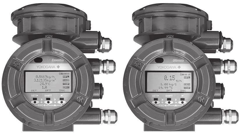
41 Remote type ATEX Technical data Connection to Rotamass 3 sensor If a Rotamass Essential or Ultimate transmitter was configured for use at a remote type Rotamass 3 sensor via the MS code, the maximum input and output values of the Rotamass 3 sensor must be observed; see the corresponding operating instructions. Tab. 2: Maximum output values, connection terminals Rotamass TI transmitter to Rotamass 3 sensor Connection terminals Voltage U o in V Current I o in ma Power P o in mw Inductance L o in mh Electrical capacitance C o in µf IIC IIB IIC IIB IIC IIB IIC IIB IIC IIB D+/D S1+/S1- or S2+/ S2- TP1, TP2, TP The medium temperature ranges of the Rotamass 3 sensor must be observed. The corresponding documentation of the Rotamass 3 is applicable to the respective sensor. The medium temperature range specified in this document applies to the transmitter, see Transmitter [} 38]. IM 01U10X01-00EN-R_002, 2nd edition, / 62
42 ATEX Technical data Ex code 9.3 Ex code The Ex code, in combination with the MS code positions 2 and 10, allows determining the maximum medium and ambient temperatures for every temperature according to the Ex certificate. In each case, it is located on the additional nameplate [} 6] of the sensor, except for Rotamass Nano and all high-temperature versions. No Ex code is available for these devices so that the medium temperature ranges must be taken directly from the chapter specification by temperature es [} 46]. 35 MHzxkg/h 16.8 kg/l 144 HZ DEKRA 15ATEX0023X Ex ib IIC T6...T1 Gb or Ex ib IIIC T150 o C Db SEE CERTIFICATE FOR DATA IP66/67 II 2 G II 2 D i Fig. 7: Additional nameplate with Ex code Ex code design The Ex code is a 6-digit key with the following design: a. p6. p5. p4. p3. p2 a p6 p5 p4 p3 p2 Ambient temperature column number Line number of maximum process temperature for temperature T6 Line number of maximum process temperature for temperature T5 Line number of maximum process temperature for temperature T4 Line number of maximum process temperature for temperature T3 Line number of maximum process temperature for temperature es T2 and T Determining the maximum temperatures based on the Ex code The specific example below is intended to explain how to determine the maximum medium and ambient temperatures based on the Ex code and the MS code. The complete tables of the medium temperature range are listed in the "Annex 1" of the Ex certificate. Option (L or Y ) determines table a or b for remote variants. This example presents only excerpts thereof. The following steps are performed to determine the maximum temperatures: Determining the maximum process temperature T pro,max based on the Ex code, positions p6...p2 Determining the maximum ambient temperature T amb pre based on the following criteria: MS code position 2 and 10 Ex code, position a Determined maximum process temperatures T pro,max 42 / 62 IM 01U10X01-00EN-R_002, 2nd edition,
43 Ex code ATEX Technical data Problem definition: The allowed medium and ambient temperatures for a Rotamass Supreme 34 are to be determined based on the Ex code and the MS code on the nameplates. The following MS code and Ex code are given: US34S-40CA40-OC5A-KF22-2-JR1/L / bar 60bar -40 to +60 o C 150 o C i 35 MHzxkg/h 16.8 kg/l 144 HZ DEKRA 15ATEX0023X Ex ib IIC T6...T1 Gb or Ex ib IIIC T150 o C Db SEE CERTIFICATE FOR DATA IP66/67 II 2 G II 2 D i U S 34 S - 40 CA4 0-0 C5 A - KF JR 1 / Fig. 8: MS code based on nameplate L a. p6. p5. p4. p3. p2 Fig. 9: Ex code based on nameplate Determining the maximum process temperature T pro,max The values of the Ex code on the nameplate p6...p2 are the line indexes that determine the maximum process temperatures T pro,max according to Table 6 in the Ex certificate. The temperature determines the applicable column. Tab. 3: Excerpt from the medium temperature table of the Ex certificate: "Table 6: Process temperatures according Ex-Code" p2 to p6 Ex-Code values T pro, max : for temperature es T6 T5 T4 T3 T2 T IM 01U10X01-00EN-R_002, 2nd edition, / 62
44 ATEX Technical data Ex code Determining the maximum ambient temperature T amb pre For the temperature es, this results in the following values for the maximum process temperature: T6 (column T6) and value of Ex code p6 (value = 68) define the intersection: T pro, max = 49 C T5 (column T5) and value of Ex code p5 (value = 67) define the intersection: T pro, max = 63 C T4 (column T4) and value of Ex code p4 (value = 65) define the intersection: T pro, max = 96 C T3 (column T3) and value of Ex code p3 (value = 63) define the intersection: T pro, max = 159 C T2 (column T2) and value of Ex code p2 (value = 39) define the intersection: T pro, max = 179 C T1 (column T1) and value of Ex code p2 (value = 39) define the intersection: T pro, max = 179 C These maximum process temperatures established must be used for further determination of the ambient temperatures. The following is required for determining the maximum ambient temperatures: MS code position 2, 10 and 15 Ex code, position a Determined maximum process temperatures T pro,max U S34S -40CA4 0-0C5 A -KF22-2 -JR1 / L005 Fig. 10: MS code a. p6. p5. p4. p3. p2 Fig. 11: Ex code T6 49 C T5 63 C T4 96 C T3 159 C T2 179 C T1 179 C Maximum process temperature T pro,max First, the correct product-dependent table for the ambient temperature must be identified. To do so, the values of the positions 2 and 10 of the MS code on the nameplate are compared with the information of the table titles in Table of the annex to the Ex certificate. A match determines the table to be applied. In this case table 9a is valid, because no option Y is present in the MS-Code. The first digit of the Ex code, a = 3, defines the applicable columns T6...T1 within the located ambient temperature table. 44 / 62 IM 01U10X01-00EN-R_002, 2nd edition,
45 Ex code ATEX Technical data The maximum process temperatures T pro,max established define the applicable lines within the located ambient temperature table. If a value of the maximum process temperature is not listed in the table, the next higher temperature value is used. Determined maximum process temperature Next higher process temperature Tab. 4: Excerpt from the ambient temperature table of the Ex certificate: "Table 9a: Ambient temperature table for designs: [2.] - - [10.]- - / Applicable for Model Code part values: [2.] = S, G, C, L,T; [10.] = A, C, E, J" T amb pre a:... a = 2 a = 3 a = 4... T pro in C... T6 T5 T4 T3 T2 T1 T6 T5 T4 T3 T2 T1 T6 T5 T4 T3 T The value determined based on the ambient temperature table is a temporary value of the ambient temperature. Next, it must be compared with the determined maximum process temperature. The lower value determines the actual maximum ambient temperature. T1... Result Determined maximum process temperature Determined temporary value for the ambient temperature Maximum ambient temperature 49 T T T T T T IM 01U10X01-00EN-R_002, 2nd edition, / 62
46 ATEX Technical data specification by temperature es 9.4 specification by temperature es Maximum ambient and process temperatures depending on explosion groups and temperature es can be determined via the MS code or via the MS code together with the Ex code Identification via MS code The following tables provide an overview of where the tables of the temperature specifications are located based on MS code and explosion group. Rotamass Nano, CNG, LPG Medium temperature range MS code Position 8 Standard 0 Standard 0 Mid-range 2 Housing design Remote type, standard terminal box Remote type, long neck Remote type, long neck MS code Position 10 specification for the explosion groups A, C, E, J IIC, IIB [} 50] B, D, F, K IIC, IIB [} 50] B, D, F, K IIC, IIB [} 50] Rotamass Supreme, CNG, LPG and Intense Medium temperature range MS code Position 8 Housing design MS code Position 10 Standard 0 Integral type 0, 1, 2 Standard 0 Remote type, standard terminal box A, C, E, J Standard 0 Remote type, long neck B, D, F, K Mid-range 2 Remote type, long neck B, D, F, K High 3 Remote type, long neck B, D, F, K specification for the explosion groups IIC IIB IIC IIB IIC IIB IIC IIB IIC IIB [} 51] [} 51] [} 51] [} 52] [} 52] [} 52] [} 53] [} 53] [} 53] [} 52] 46 / 62 IM 01U10X01-00EN-R_002, 2nd edition,
47 specification by temperature es ATEX Technical data Rotamass Giga Medium temperature range MS code Position 8 Housing design MS code Position 10 Standard 0 Integral type 0, 1, 2 Standard 0 Remote type, standard terminal box A, C, E, J Standard 0 Remote type, long neck B, D, F, K IIC Mid-range 2 Remote type, long neck B, D, F, K IIC specification for the explosion groups IIC IIB IIC IIB IIB IIB [} 54] [} 54] [} 54] [} 55] [} 55] [} 55] [} 56] [} 56] High 3 Remote type, long neck B, D, F, K IIC, IIB [} 56] IM 01U10X01-00EN-R_002, 2nd edition, / 62
48 ATEX Technical data specification by temperature es Rotamass Prime and Hygienic MS code Position Housing design MS code Position 10 Device option MS code Position 15 specification for the explosion groups Integral type 0, 1, 2 IIC, IIB [} 57] Integral type 0, 1, 2 Expanded temperature range /EPT IIC, IIB [} 57] 50 Integral type 0, 1, 2 IIC, IIB [} 57] 50 Integral type 0, 1, 2 Expanded temperature range 80 Integral type 0, 1, 2 /EPT IIC, IIB [} 58] IIC IIB [} 58] [} 58] 1H Integral type 0, 1, 2 IIC, IIB [} 59] 25 Remote type, 40 standard terminal box 25 Remote type, 40 standard terminal box H Remote type, standard terminal box Remote type, standard terminal box Remote type, standard terminal box Remote type, standard terminal box A, C, E, J IIC, IIB [} 59] A, C, E, J Expanded temperature range /EPT IIC, IIB [} 59] A, C, E, J IIC, IIB [} 60] A, C, E, J Expanded temperature range A, C, E, J /EPT IIC, IIB [} 60] IIC IIB [} 60] [} 61] A, C, E, J IIC, IIB [} 61] 48 / 62 IM 01U10X01-00EN-R_002, 2nd edition,
Ex instruction manual. Rotamass Coriolis mass flow meter. IECEx. IM 01U10X02-00EN-R_002, 2nd edition,
 Ex instruction manual Rotamass Coriolis mass flow meter IM 01U10X02-00EN-R_002, 2nd edition, 2016-09-22 Table of contents Table of contents 1 Introduction... 4 1.1 Scope of application... 4 1.2 Applicable
User's Manual. ROTAMASS Total Insight Coriolis Mass Flow and Density Meter Explosion Proof Type Manual IECEx IM 01U10X02-00EN-R
 User's Manual ROTAMASS Total Insight Coriolis Mass Flow and Density Meter Explosion Proof Type Manual IECEx IM 01U10X02-00EN-R IM 01U10X02-00EN-R, 3rd edition, 2017-11-16 Table of contents Table of contents
DPharp Differential Pressure and Pressure Transmitters
 User s Manual DPharp Differential Pressure and Pressure s Manual Change No. 12-021-2 For the products of EJX and EJA-E series with any of the following option codes, please refer to this manual change
Rev ECN Description Approval Date AA Release to Approvals RCS 10/9/12
 EB-20023137 Revision: AA Number of Pages: 13 Comments: Originator: RCS 10/05/12 Approved: RCS 10/05/12 Rev ECN Description Approval Date AA 1049085 Release to Approvals RCS 10/9/12 Micro Motion, Inc. Page
Power supply. Calibration. Surface finishing. Seal. Process connection
 Page 1 of 6 Description The measuring system is designed for flow measurement. Gas flow through the sensing section passes two PT 100 RTD transducers; one is used as a temperature sensing device whilst
Annex 1 to Certificate of Conformity IECEx KEM X Issue No. 8 Rota Yokogawa Rotamass 3 Series Coriolis Mass Flowmeter
 Description RotaMass 3 Series Coriolis Mass Flow Meter; - Integral Transmitter, Model RCCx; - Remote Converter, Model RCCF31; - Remote Converter, Model RCCR31; - Remote Detector Model RCCS3xxxx The Coriolis
OPTIWAVE 7300 C Supplementary instructions
 OPTIWAVE 7300 C Supplementary instructions Radar (FMCW) Level Transmitter for agitated liquids in process applications Supplementary Instructions for ATEX applications KROHNE CONTENTS OPTIWAVE 7300 C General
Rotamass TI Coriolis Mass flow meter
 General Specifications Rotamass TI Coriolis Mass flow meter Rotamass Prime Scope of application Precise flow rate measurement of fluids and gases, multi-phase media and media with specific gas content
Temperature Input Module for Zone 1 Series 9482/32
 www.stahl.de > 8 channels for temperature sensors > Intrinsically safe inputs Ex ia > For Pt-, Ni- and Cu-resistance temperature detectors according to DIN, IEC and GOST in 2-, 3- and 4-wire circuits >
Transducer transmitter BILT 4 II 2(1) G. Technical Manual
 G. Technical Manual") GB Transducer transmitter BILT 4 II 2(1) G Technical Manual Transducer transmitter BILT 4 Contents Introduction General... 3 Ex.safety description... 4 Technical data... 5 Installation General... 6 Mechanical
GB Transducer transmitter BILT 4 II 2(1) G Technical Manual Transducer transmitter BILT 4 Contents Introduction General... 3 Ex.safety description... 4 Technical data... 5 Installation General... 6 Mechanical
Rotamass TI Coriolis Mass flow meter
 General Specifications Rotamass TI Coriolis Mass flow meter Rotamass Supreme Scope of application Precise flow rate measurement of fluids and gases, multi-phase media and media with specific gas content
CoriolisMaster FCB130, FCB150, FCH130, FCH150 Coriolis Mass Flowmeter
 Operating Instruction OI/FCB100/FCH100-EN Rev. D CoriolisMaster FCB130, FCB150, FCH130, FCH150 Coriolis Mass Flowmeter Measurement made easy Change from one to two columns Short product description Coriolis
Safety Instructions Proline Promass 300
 XA01507D/06/EN/01.16 71327925 Products Solutions Services Safety Instructions Proline Promass 300 Class I, Zone 2 AEx/Ex na ic IIC Class I, Zone 2, AEx/Ex na nc ic IIC Class I Division 2 C US Document:
INSTRUCTION MANUAL (ATEX / IECEx)
") INSTRUCTION MANUAL (ATEX / IECEx) STExS1 & STExS2 Sounder For use in Flammable Gas and Dust Atmospheres 1) Warnings DO NOT OPEN WHEN AN EXPLOSIVE ATMOSPHERE IS PRESENT POTENTIAL ELECTROSTATIC CHARGING
INSTRUCTION MANUAL (ATEX / IECEx) STExS1 & STExS2 Sounder For use in Flammable Gas and Dust Atmospheres 1) Warnings DO NOT OPEN WHEN AN EXPLOSIVE ATMOSPHERE IS PRESENT POTENTIAL ELECTROSTATIC CHARGING
IECEx Hazardous Area Approvals Fisher FIELDVUE DVC6200 Series Digital Valve Controllers
 Instruction Manual Supplement DVC6200 Digital Valve Controllers IECEx Hazardous Area Approvals Fisher FIELDVUE DVC6200 Series Digital Valve Controllers SIS Hazardous Area Approvals and Special Instructions
Safety Instructions Proline Promag 500
 XA01524D/06/EN/01.16 71327947 Products Solutions Services Safety Instructions Proline Promag 500 Cl.I, II, III Div.1 for XP (Ex d Flameproofed version) C US Document: XA01524D Safety instructions for electrical
Attachment to Certificate IECEx PTB X
 Applicant: Electrical Apparatus: KROHNE Ltd. Measuring converter, type MFC400F Description of equipment The measuring converter, type MFC400F is used as part of a mass flow measuring system to determine
Rev ECN Description Approval Date AA Release to Approvals RCS 10/9/12
 EB-20023139 Revision: AA Number of Pages: 13 Comments: Originator: RCS 10/05/12 Approved: RCS 10/05/12 Rev ECN Description Approval Date AA 1049085 Release to Approvals RCS 10/9/12 Micro Motion, Inc. Page
Pressure transmitters MBS 4201, MBS 4251, MBS 4701 and MBS 4751
 060R9345 Instructions Pressure transmitters MBS 4201, MBS 4251, MBS 4701 and MBS 4751 Content Page 1 Description/application 2 Identification 3 Specifications 4 Safety instructions 5 Installation/dimensions
Analog Input Module HART Ex i / I.S. Inputs, Channels Type 9461/
 > 4 channels for 2-wire HART transmitters and 4 channels for 4-wire HART transmitters > Intrinsically safe inputs Ex ia IIC > Galvanic separation between inputs and system > Open-circuit and short-circuit
Solexy USA, LLC International Blvd Cincinnati, Ohio Phone: Fax:
 OVERVIEW The Solexy RX series explosion proof and intrinsically safe antenna coupler is an integrated protection device that facilitates non-ex certified radio antenna installation in hazardous areas.
2-WIRE UNIVERSAL TEMPERATURE TRANSMITTER
 SAFE INSTALLATION MANUAL (FM APPROVAL) -WIRE UNIVERSAL TEMPERATURE TRANSMITTER (HART communication, intrinsically safe/explosion-proof) MODEL B6U/B6U-B BEFORE USE... SAFETY PRECAUTIONS This manual describes
Micro Motion Model 5700 Transmitter ATEX Zone 2/22 Installation Instructions II 3 G or II 3 (2) G/EPL Gc & II 3 D/EPL Dc
 G/EPL Gc & II 3 D/EPL Dc") ATEX Installation Instructions EB-20025742 Rev. AC December 2015 Micro Motion Model 5700 Transmitter ATEX Zone 2/22 Installation Instructions II 3 G or II 3 (2) G/EPL Gc & II 3 D/EPL Dc 5700 ATEX Installation
ATEX Installation Instructions EB-20025742 Rev. AC December 2015 Micro Motion Model 5700 Transmitter ATEX Zone 2/22 Installation Instructions II 3 G or II 3 (2) G/EPL Gc & II 3 D/EPL Dc 5700 ATEX Installation
Analog Universal Module HART for Zone 2 Series 9468/33
 > 8 channels can be adjusted individually as analog inputs or outputs > Intrinsically safe inputs/outputs Ex ia > For 0/4 20 ma + HART signals > Line fault monitoring per channel > Diagnostics based on
Safety Instructions Nivotester FTC625, FTC325
 XA01351F-A/00/EN/01.14 71273077 Products Solutions Services Safety Instructions FTC625, FTC325 [Ex ia Ga] IIC/IIB TÜV 13.0903 X Segurança TÜV INMETRO OCP 0004 Document: XA01351F-A Safety instructions for
Installation guide 971 SmartRadar LTi
 Installation guide 971 SmartRadar LTi March 2009 Part no. 4416.715 Revision 3 Enraf B.V. P.O. Box 812 2600 AV Delft Netherlands Tel. : +31 15 2701 100 Fax : +31 15 2701 111 E-mail : enraf-nl@honeywellenraf.nl
Digital Input Output Module for Zone 2 Series 9470/33
 www.stahl.de > 16 channels can be adjusted in pairs as digital input or output > Intrinsically safe inputs/outputs Ex ia > For contacts, NAMUR proximity switches and low-power solenoid valves > Up to 8
ATEX Installation Drawings and Instructions
 Installation Instructions P/N 20004414, Rev. C September 2008 ATEX Installation Drawings and Instructions For ATEX-approved transmitter installations Note: For hazardous installations in Europe, refer
General Specifications
 General Specifications EJX Series FOUNDATION TM Fieldbus Communication FOUNDATION fieldbus is the digital communication line for the field instruments, whose signal is internationally standardized by Fieldbus
OPTITEMP TT 10 C/R Technical Datasheet
 OPTITEMP TT 10 C/R Technical Datasheet Analogue 2-wire temperature transmitter Temperature linear 4...20 ma output Rangeable with solder pads and potentiometers Easy wiring through large center hole The
Digital Input Output Module for Zone 2 Series 9470/33
 www.stahl.de > 16 can be adjusted in pairs as digital input or output > Intrinsically safe inputs/outputs Ex ia > For contacts, NAMUR proximity switches and low-power solenoid valves > Up to 8 can be used
PROline promag 53 Division 1
 XA 040D/06/en/05.01 50099923 FM+SGML 6.0 PROline promag 53 Division 1 Ex Ex documentation for the BA 053D and BA 054D operating instructions according to FACTORY MUTUAL standards documentation for the
User manual. Load cell with one built in amplifier KOSD-FA KIMD-FA KEND-FA Load cell with two built in amplifiers KOSD-FAD KIMD-FAD KEND-FAD
 User manual Load cell with one built in amplifier KOSD-FA KIMD-FA KEND-FA Load cell with two built in amplifiers KOSD-FAD KIMD-FAD KEND-FAD Contents Precautions Intended use General 1 Specification 3
Digital Input Module NAMUR Ex i / I.S. Inputs, 16 Channels for Zone 1 / Div. 1 Series 9470/22
 www.stahl.de > 16 channels for contacts and NAMUR proximity switches (EN 60947-5-6) > Intrinsically safe inputs Ex ia IIC > Galvanic separation between inputs and system > Open-circuit and short-circuit
Digital Input Output Module for Zone 1 Series 9470/32
 www.stahl.de > 16 can be adjusted in pairs as digital input or output > Intrinsically safe inputs/outputs Ex ia > For contacts, NAMUR proximity switches and low-power solenoid valves > Up to 8 can be used
Proline Promass 40. Safety Instructions. NEPSI Zone 1, Zone 21
 Safety Instructions Proline Promass 40 NEPSI Zone 1, Zone 21 This document is an integral part of the following Operating Instructions: BA00061D, Proline Promass 40 HART Contents General warnings.......................................................................
Safety Instructions Proline Promass 100
 XA00160D/06/EN/03.14 71261250 Products Solutions Services Safety Instructions Proline Promass 100 Modbus RS485 Cl.I Div.1, Zone 1 for IS (Ex i Intrinsically safe version) C US Document: XA00160D Safety
Micro Motion Model 5700 Transmitter IECEx Zone 2/22 Installation Instructions EPL Gc and EPL Dc
 IECEx Installation Instructions EB-20025744 Rev. AC December 2015 Micro Motion Model 5700 Transmitter IECEx Zone 2/22 Installation Instructions EPL Gc and EPL Dc 5700 IECEx Installation Instructions EB-20025744
Inductive sensor slot-type SI2-K08-AP7
 SI2-K08-AP7 Slot sensor, height 8 mm Plastic, polypropylene Mechanical end stop, removable, for analog pointer instruments 3-wire DC, 10 30 VDC NO contact, PNP output Cable connection Wiring diagram Type
YTA610 and YTA710 Temperature Transmitters (Hardware)
") User s Manual YTA610 and YTA710 Temperature Transmitters (Hardware) 4th Edition 1 YTA610 and YTA710 Temperature Transmitters (Hardware) 4th Edition CONTENTS 1. Preface... 1-1 Notes on the User s Manual...
User s Manual YTA610 and YTA710 Temperature Transmitters (Hardware) 4th Edition 1 YTA610 and YTA710 Temperature Transmitters (Hardware) 4th Edition CONTENTS 1. Preface... 1-1 Notes on the User s Manual...
Installation guide 970, 971 and 973 series SmartRadar
 Installation guide 970, 971 and 973 series SmartRadar August 2008 Part no. 4416.719 Rev. 1 Enraf BV PO Box 812 2600 AV Delft Netherlands Tel. : +31 15 2701 100 Fax : +31 15 2701 111 E-mail : enraf-nl@honeywell.com
Digital Input Module 24 V Ex n Inputs, 16 Channels Series 9471
 > 16 channels for active 0 / 24 V signals > Zone 2 / Division 2 version for connection of circuits acc. to Ex nl, Ex na, Nonincendive and Non-Ex > Galvanic separation between inputs and system > Two channels
Glass-fibre-reinforced polycarbonate. Dead zone Adaptive or fixed from % 1.5 s adjustable. 20 ms. 60 ms. 60 ms. Approx. 1.
 General data Mounting On linear actuators On quarter turn actuators ARCA-integrated or to VDI/VDE 3847-1 or IEC 534-6 (NAMUR) Range of stroke: 3... 130 mm Integrated to VDI/VDE 3847-2 or VDI/VDE 3845 Angle
Expert 1400 / Expert 3400 Submersible Hydrostatic Level Transmitters
 Expert 1400 / Expert 3400 Submersible Hydrostatic Level Transmitters ll 2G EEx ia llc T6 As our products are continuously improved, we reserve the right to make any change in the stated specifications
General Specifications
 General Specifications ROTAMASS Total Insight Coriolis Mass Flow and Density Meter GS 01U10B02-00EN-R Scope of application Advantages and benefits Precise flow rate measurement of fluids and gases, multi-phase
Installation guide 877 FDI Field Display & Interface
 Installation guide 877 FDI Field Display & Interface November 2008 Part no. 4416.264 Rev. 5 Enraf BV PO Box 812 2600 AV Delft Netherlands Tel. : +31 15 2701 100 Fax : +31 15 2701 111 E-mail : enraf-nl@honeywell.com
Intrinsically safe pressure transmitter MBS 4201, MBS 4251, MBS 4701 and MBS 4751
 Data sheet Intrinsically safe pressure transmitter MBS 420, MBS 425, MBS 470 and MBS 475 The intrinsically safe pressure transmitter program is designed for use in hazardous environments and offers a reliable
Miniature resistance thermometer Explosion-protected version Model TR34, thread-mounted
 Electrical temperature measurement Miniature resistance thermometer Explosion-protected version Model TR34, thread-mounted WIKA data sheet TE 60.34 Applications Machine building, plant and vessel construction
ROTAMASS Total Insight Coriolis Mass Flow and Density Meter Supreme
 General Specifications ROTAMASS Total Insight Coriolis Mass Flow and Density Meter Scope of application Advantages and benefits Precise flow rate measurement of fluids and gases, multi-phase media and
Certificate of Compliance
 Certificate of Compliance Certificate: 70163240 (166720) Issued to: WIKA Alexander Wiegand SE & Co. KG Alexander-Wiegand-Str 30 Klingenberg, Bayern 63911 GERMANY Attention: Harald Gollas The products listed
[ Rosemount 648 Wireless Temperature Transmitter. Rosemount 648 Wireless. Quick Installation Guide , Rev CA August 2011
 Quick Installation Guide Temperature Transmitter Start Wireless Considerations Step 1: Physical Installation Step 2: Verify Operation Reference Information Product Certifications End www.rosemount.com
OPTIMASS / 300 / 010 Guidelines for the use of Coriolis meters in hazardous areas
 OPTIMASS / 300 / 010 Guidelines for the use of Coriolis meters in hazardous areas 1000 Series Twin Straight Tube Coriolis Mass Flowmeter 2000 Series Twin Straight Tube Coriolis Mass Flowmeter 3000 Series
General Specifications
 General Specifications ROTAMASS Total Insight Coriolis Mass Flow and Density Meter GS 01U10B04-00EN-R Scope of application Advantages and benefits Precise flow rate measurement of fluids and gases, multi-phase
RHE12. Hazardous Area Coriolis Mass Flow Transmitter. Features. Applications. Benefits
 RHE12 Hazardous Area Coriolis Mass Flow Transmitter Features Field mounting Compact, pressure safe housing ATEX and CSA approvals for installation in hazardous areas 24 VDC power supply Configurable analog
Rosemount 848L Logic Transmitter with FOUNDATION Fieldbus
 Logic Transmitter with FOUNDATION Fieldbus Integrates Discrete I/O on a FOUNDATION Fieldbus H1 Segment Reduces Installation and Maintenance Costs with a Single Network for Analog and Discrete devices Easily
Intrinsically Safe Compact Controller CTR 210i. Intrinsically Safe Bargraph Indicator. BGI 210i
 Intrinsically Safe Compact Controller CTR 210i Intrinsically Safe Bargraph Indicator BGI 210i DMT 02 ATEX E 148 2. Supplement also grahics display Revision 4 IBS BatchControl GmbH Im Sträßchen 2 4 Tel.:
Specifications. Specifications. Transfer Characteristics Accuracy at 20 C (68 F) Temperature Drift
 Temperature Drift") Appendix A Specifications 1797-IE8 and -IE8NF Input Modules Specifications Number of Inputs IS Input Type IS Module Type Resolution Transfer Characteristics Accuracy at 20 C (68 F) Temperature Drift Functional
Appendix A Specifications 1797-IE8 and -IE8NF Input Modules Specifications Number of Inputs IS Input Type IS Module Type Resolution Transfer Characteristics Accuracy at 20 C (68 F) Temperature Drift Functional
Installation Instructions P/N MMI , Rev. AA July ATEX Installation Instructions for Micro Motion Model RFT9739 Transmitters
 Installation Instructions P/N MMI-20011709, Rev. AA July 2009 ATEX Installation Instructions for Micro Motion Model RFT9739 Transmitters Note: For hazardous installations in Europe, refer to standard EN
TÜV NORD CERT. TÜV NORD CERT GmbH & Co. KG Am TÜV 1 D Hannover. Annexe to IECEx TUN , issue No. 0 Page 1 of 5.
 GmbH & Co. KG Page 1 of 5 Electrical data: Base devices for 6DR50**-*****-**** Motherboard L250 Power supply / control current 4-20 ma... series connection (terminals 6+ and 7/8) 2-wire circuit with Hart
Installation Instructions P/N MMI , Rev. AA July ATEX Installation Instructions for Micro Motion Model 3500 Transmitters
 Installation Instructions P/N MMI-20011707, Rev. AA July 2009 ATEX Installation Instructions for Micro Motion Model 3500 Transmitters Note: For hazardous installations in Europe, refer to standard EN 60079-14
User manual. Load cell with one built in amplifier KOSD-FA KIMD-FA KEND-FA Load cell with two built in amplifiers KOSD-FAD KIMD-FAD KEND-FAD
 User manual Load cell with one built in amplifier KOSD-FA KIMD-FA KEND-FA Load cell with two built in amplifiers KOSD-FAD KIMD-FAD KEND-FAD Contents Precautions Intended use General 1 Specification 3
Remote I/O. 74 Remote I/O. Remote I/O System
 System Overview of the System Components IS1+ 76 General Information IS1+ 77 CPU & Power Modules CPU & Power Modules for Zone 1 / Div. 1 IS1+ 9440/22 78 Sockets for CPU & Power Module IS1+ 9490 78 CPU
Glass-fibre-reinforced polycarbonate. Dead zone Adaptive or fixed from % 20 ms. 60 ms. 60 ms. Approx. 1.3 kg. Approx. 0.9 kg. Approx. 5.
 General data Mounting On linear actuators On quarter turn actuators ARCA-integrated or to VDI/VDE 3847-1 or IEC 534-6 (NAMUR) Range of stroke: 3... 130 mm Integrated to VDI/VDE 3847-2 or VDI/VDE 3845 Angle
User s Manual. Manual Change No V-E. Please use the attached sheets for the pages listed below in IM 01F06F00-01EN (7th).
.") User s Manual Model DY Vortex Flowmeter (Integral Type, Remote Type) Model DYA Vortex Flow Converter (Remote Type) FOUNDATION Fieldbus Communication Type Manual Change No.14-013V-E Please use the attached
User s Manual Model DY Vortex Flowmeter (Integral Type, Remote Type) Model DYA Vortex Flow Converter (Remote Type) FOUNDATION Fieldbus Communication Type Manual Change No.14-013V-E Please use the attached
Digital Input Output Module 24 V for Ex n Zone 2 Series 9472/35
 www.stahl.de > 16 channels can be adjusted in pairs as digital inputs or outputs > Suitable for NAMUR proximity switches, 3-wire PNP proximity switches, contacts and solenoid valves (24 V / 0.5 A). > Up
SINEAX TI 807 Passive DC signal isolator. SINEAX TI 807 Passive DC signal isolator
 SINEAX TI 807 without power supply, Ex- and non-ex version, in housing N17 or S17 for rail and wall mounting 0102 II (1) G resp. II (2) G Application The signal isolator SINEAX TI 807 serves to electrically
SINEAX TI 807 Passive DC signal isolator
 without power supply, Ex- and non-ex version, in housing N17 or S17 for rail and wall mounting 0102 II (1) G resp. II (2) G Application The signal isolator SINEAX TI 807 serves to electrically insulate
CSA Hazardous Area Approvals Fisher FIELDVUE DVC6005 Series Remote Mount Digital Valve Controllers
 Instruction Manual Supplement DVC6005 Digital Valve Controllers CSA Hazardous Area Approvals Fisher FIELDVUE DVC6005 Series Remote Mount Digital Valve Controllers Hazardous Area Approvals and Special Instructions
RHE11. Hazardous Area Multifunction Coriolis Flow Transmitter. Features. Applications. Benefits
 RHE11 Hazardous Area Multifunction Coriolis Flow Transmitter Features Wall or Pipe Bracket Mount Built in safety barriers allow operation with RHM sensor in hazardous area Selectable Metric and English
Introduction. Additional Information. Temperature transmitter for HART protocol. Suitable for all standard requirements. Measurement made easy
 ABB MEASUREMENT & ANALYTICS COMMISSIONING INSTRUCTION TTF200 Field-mount temperature transmitter Temperature transmitter for HART protocol. Suitable for all standard requirements Measurement made easy
Installation guide 873 SmartRadar Control Unit & Antenna Unit
 Installation guide 873 SmartRadar Control Unit & Antenna Unit Rev. 7 January 2006 Part no. 4416.569 Enraf BV PO Box 812 2600 AV Delft Netherlands Tel. : +31 15 2701 100 Fax : +31 15 2701 111 E-mail : info@enraf.nl
INSTALLATION AND OPERATION MANUAL
 Version 2.2 MS1016 MTF SERIES VIBRATING PROBES FOR LIQUIDS AND HYC-PKK-312 SWITCHING ISOLATOR INSTALLATION AND OPERATION MANUAL Hycontrol Limited, Larchwood House, Orchard Street, Redditch, Worcestershire,
MT MOTORI ELETTRICI. Installation, operation, maintenance and safety manual for motors used in hazardous areas 1-II-2G 21-II-2D
 MT MOTORI ELETTRICI Installation, operation, maintenance and safety manual for motors used in hazardous areas 1-II-2G 21-II-2D TABLE OF CONTENTS 1. Introduction 2. Scope of application 3. Installation
Process transmitter Model UPT-20, with pressure port Model UPT-21, with flush diaphragm
 Electronic pressure measurement Process transmitter Model UPT-20, with pressure port Model UPT-21, with flush diaphragm WIKA data sheet PE 86.05 Applications Process technology Machine building and plant
CSA Hazardous Area Approvals Fisher FIELDVUE DVC6200 Series Digital Valve Controllers
 Instruction Manual Supplement DVC6200 Digital Valve Controllers CSA Hazardous Area Approvals Fisher FIELDVUE DVC6200 Series Digital Valve Controllers SIS Hazardous Area Approvals and Special Instructions
STT 3000 Series STT170 SMART TEMPERATURE TRANSMITTER Models STT171, STT173, STT17H, STT17F, STT17C
 STT 3000 Series STT170 SMART TEMPERATURE TRANSMITTER Models STT171, STT173, STT17H, STT17F, STT17C 6/07 PRODUCT SPECIFICATION SHEET OVERVIEW The Honeywell STT170 series of programmable temperature transmitters
YTA610 and YTA710 Temperature Transmitter (Hardware)
") User s Manual YTA610 and YTA710 Temperature Transmitter (Hardware) 2nd Edition 1 YTA610 and YTA710 Temperature Transmitter (Hardware) 2nd Edition CONTENTS 1. Preface... 1-1 Notes on the User s Manual...1-1
User s Manual YTA610 and YTA710 Temperature Transmitter (Hardware) 2nd Edition 1 YTA610 and YTA710 Temperature Transmitter (Hardware) 2nd Edition CONTENTS 1. Preface... 1-1 Notes on the User s Manual...1-1
Rudder or propeller angular position transmitter KINAX WT720
 Description The is a robust, absolute angular position transmitter, which is particularly suitable for use in marine applications such as the detection of rudder or propeller positions. In contrast to
Installation guide 970 SmartRadar ATi
 Installation guide 970 SmartRadar ATi July 2008 Part no. 4416.717 Rev. 3 Enraf B.V. P.O. Box 812 2600 AV Delft Netherlands Tel. : +31 15 2701 100 Fax : +31 15 2701 111 E-mail : enraf-nl@honeywell.com Website
Digital temperature transmitter for resistance sensors Model T15.H, head mounting version Model T15.R, rail mounting version
 Temperature Digital temperature transmitter for resistance sensors Model T15.H, head mounting version Model T15.R, rail mounting version WIKA data sheet TE 15.01 for further approvals see page 10 Applications
Operator Manual. Transmitters Series KAT-... Analog transmitters in 2-wire technique
 Operator Manual Transmitters Series KAT-... Analog transmitters in 2-wire technique Important Safety Notes! In the case of non-observance of the installation and safety notes or improper use of the transmitter
ROTAMASS Total Insight Coriolis Mass Flow and Density Meter Intense
 General Specifications ROTAMASS Total Insight Coriolis Mass Flow and Density Meter Intense Scope of application Advantages and benefits Precise flow rate measurement of fluids and gases, multi-phase media
FM Hazardous Area Approvals Fisher FIELDVUE DVC6200 Series Digital Valve Controllers
 Instruction Manual Supplement DVC6200 Digital Valve Controllers FM Hazardous Area Approvals Fisher FIELDVUE DVC6200 Series Digital Valve Controllers SIS Hazardous Area Approvals and Special Instructions
FLEX Ex V ac In/Quad-Ex dc Out Power Supply
 Installation Instructions FLEX Ex 85 250V ac In/Quad-Ex dc Out Power Supply Catalog Number 1797-PS1N Topic Important User Information 2 About the Power Supplies 3 Understand System Planning 4 Electrostatic
OEM miniature resistance thermometer Models TR31-3 and TR31-K, thread-mounted
 Electrical temperature measurement OEM miniature resistance thermometer Models TR31-3 and TR31-K, thread-mounted WIKA data sheet TE 60.31 further approvals see page 10 Applications Machine building, plant
CERTIFICATE OF COMPLIANCE
 FM Approvals 1151 Boston Providence Turnpike P.O. Box 9102 Norwood, MA 0202 USA T: 781 72 400 F: 781-72-975 www.fmapprovals.com CERTIFICATE OF COMPLIANCE HAZARDOUS (CLASSIFIED) LOCATION ELECTRICAL EQUIPMENT
Mid-West. Instrument. Model 140 Electrical Installation and Operating Instructions. Gauge Front ELECTRICAL
 Mid-West Instrument BULLETIN NO. ELEC-IM140/11A Replaces ELEC-IM140-141/09A ELECTRICAL Gauges with switches have one or two SPST or SPDT hermetically sealed adjustable set point reed switch assemblies.
STT 3000 Series STT170 SMART TEMPERATURE TRANSMITTER Models STT171, STT173, STT17H, STT17F, STT17C
 STT 3000 Series STT170 SMART TEMPERATURE TRANSMITTER Models STT171, STT173, STT17H, STT17F, STT17C 34-TT-03-07 3/06 PRODUCT SPECIFICATION SHEET OVERVIEW The Honeywell STT170 series of programmable temperature
ED701 General Industry Pressure Transmitter
 ED701 General Industry Pressure Transmitter Standard industrial process connections Complete range of electrical connections 4... 20 ma and Voltage outputs Accuracy: 0.1%, 0.2% and 0.4% FS Quick response
DMP 343. Industrial Pressure Transmitter. Without Media Isolation. appmeas.co.uk +44 (0)
") DMP 4 Industrial Pressure Transmitter Without Media Isolation accuracy according to IEC 60770: 0.5 % FSO Nominal pressure from 0... 0 mbar up to 0... 000 mbar Product characteristics excellent linearity
DMP 4 Industrial Pressure Transmitter Without Media Isolation accuracy according to IEC 60770: 0.5 % FSO Nominal pressure from 0... 0 mbar up to 0... 000 mbar Product characteristics excellent linearity
General Specifications
 General Specifications FN510 Field Wireless Multi-Function Module GENERAL This General Specification (GS) describes the specifications for Field Wireless Multi-Function Module. Combined with Field Wireless
Proline Promass 83, 84
 Safety Instructions Proline Promass 83, 84 NEPSI Zone 1, Zone 21 This document is an integral part of the following Operating Instructions: BA00059D, Proline Promass 83 BA00109D, Proline Promass 84 BA00063D,
Operating Manual. isolate501
 Operating Manual isolate501 Document Number 413569 (See Last Page for Revision Details). Copyright Extronics Ltd, 2015 Page 2 of 21 Contents 1 Introduction... 4 2 Safety Information and Notes... 5 2.1
Isolators A3/1. Transmitter Supply Unit Field Circuit Ex i Series 9160 Rev. F
 Series 9160 Rev. F > Intrinsically safe input [Ex ia] IIC > Galvanic isolation between input, output and power supply > For use up to SIL 2, special version up to SIL 3 (IEC 61508) > High accuracy www.stahl.de
R88000 T (including ATEX)
") INSTRUCTION MANUAL R88000 T88000 (including ATEX) Factory set transmitters are ready to use. Connect according the labels. Otherwise follow the calibration instructions. Input signals ṮC RTD CONTENTS:
INSTRUCTION MANUAL R88000 T88000 (including ATEX) Factory set transmitters are ready to use. Connect according the labels. Otherwise follow the calibration instructions. Input signals ṮC RTD CONTENTS:
Installation guide 854 XTG Level Gauge
 Installation guide 854 XTG Level Gauge July 2008 Part no. 4416.276 Rev. 5 Enraf B.V. P.O. Box 812 2600 AV Delft Netherlands Tel. : +31 15 2701 100 Fax : +31 15 2701 111 E-mail : enraf-nl@honeywell.com
ATEX Installation Instructions for Micro Motion CMF400 Sensors with Booster Amplifier
 Installation Instructions P/N MMI-20010152, Rev. A June 2007 for Micro Motion CMF400 Sensors with Booster Amplifier For ATEX-approved sensor installations Note: For hazardous installations in Europe, refer
SET Installation and Operating Instructions. Level switch for two sensors
 Labkotec Oy Myllyhaantie 6 FI-33960 PIRKKALA FINLAND Tel: + 358 29 006 260 Fax: + 358 29 006 1260 20.2.2013 Internet: www.labkotec.fi 1/14 SET-2000 Level switch for two sensors Copyright 2013 Labkotec
Coriolis Massflowmeter
 Coriolis Massflowmeter for liquids and gas measuring monitoring analysing Measuring range: 0-0.8 kg / h 0-65 000 kg / h water Accuracy: ± 0.1 of reading ±zero-point stability (liquids) pmax: PN40 tmax:
PROCESS AUTOMATION MANUAL FIELDBARRIER
 PROCESS AUTOMATION MANUAL FIELDBARRIER SCHULUNG V2 With regard to the supply of products, the current issue of the following document is applicable: The General Terms of Delivery for Products and Services