Introduction. Amplitude Modulation System Angle Modulation System
|
|
|
- Ursula Leonard
- 6 years ago
- Views:
Transcription
1 Introduction Amplitude Modulation System Angle Modulation System Frequency Modulation Phase Modulation Digital Communication Elements of Information Theory Advanced Communication Techniques 1
2 Tools for communication Fourier Series Fourier Transform
3 Fourier Series Every composite periodic signal can be represented with a series of sine and cosine functions. The functions are integral harmonics of the fundamental frequency f of the composite signal. Using the series we can decompose any periodic signal into its harmonics.
4 periodic signal Periodic signals repeat with some period T, while aperiodic, or non periodic, signals do not. We can define a periodic function through the following mathematical expression, where t can be any number and T is a positive constant: f(t) =f(t + t) (1)..(1) The fundamental period of our function, f(t), is the smallest value of T that the still allows equation-1 to be true.
5 A periodic signal with period T 0 An aperiodic signal
6 Fourier Transform Fourier Transform is a tool that changes a time domain signal to a frequency domain signal and vice versa.
7 Why frequency domain analysis? Allows simple algebra rather than time-domain differential equations to be used Transfer functions can be applied to transmitter, communication channel and receiver Channel bandwidth, noise and power are easier to evaluate Easy to pick out frequencies.
 Output transducer Receiver Demodulator EM waves (modulated signal+ Noise)")
8 Basic analog communications system Baseband signal (electrical signal) Transmitter EM waves (modulated signal) Noise Input transducer Modulator Transmission Channel Carrier Baseband signal (electrical signal) Output transducer Receiver Demodulator EM waves (modulated signal+ Noise) Carrier
9 Introduction Definition of COMMUNICATION? Why do we need to communicate? Definition of COMMUNICATION SYSTEM (Electronic Communication System)? Why do we need to communicate electronically? How to communicate? Interference in communications? How to overcome? 9
10 Introduction to Communication Systems Communication Basic process of exchanging information from one location (source) to destination (receiving end). Refers process of sending, receiving and processing of information/signal/input from one point to another point. Source Flow of information Destination Figure 1 : A simple communication system 10
11 Electronic Communication System defined as the whole mechanism of sending and receiving as well as processing of information electronically from source to destination. Example Radiotelephony, broadcasting, point-to-point, mobile communications, computer communications, radar and satellite systems. 11
12 Objectives Communication System to produce an accurate replica of the transmitted information that is to transfer information between two or more points (destinations) through a communication channel, with minimum error. Besides interactive purposes, business and social 12
13 NEED FOR COMMUNICATION Interaction purposes enables people to interact in a timely fashion on a global level in social, political, economic and scientific areas, through telephones, electronic-mail and video conference. Transfer Information Tx in the form of audio, video, texts, computer data and picture through facsimile, telegraph or telex and internet. Broadcasting Broadcast information to masses, through radio, television or teletext. 13
14 Terms Related To Communications Message physical manifestation produced by the information source and then converted to electrical signal before transmission by the transducer in the transmitter. Transducer Device that converts one form of energy into another form. Input Transducer placed at the transmitter which convert an input message into an electrical signal. Example Microphone which converts sound energy to electrical energy. Message Input Transducer Electrical Signal 14
15 Output Transducer placed at the receiver which converts the electrical signal into the original message. Example Loudspeaker which converts electrical energy into sound energy. Electrical Signal Output Transducer Message Signal electrical voltage or current which varies with time and is used to carry message or information from one point to another. 15
16 Information defined as what is being conveyed by the telecommunication environment or as knowledge or facts. It can be in analogue form (voice, video, music) or digital form ( binary-coded numbers, graphics symbols or database information). 16
17 Basic Requirements of Communication Systems. Rate of Information Transfer defined as the amount of info that must be communicated from source to destination in a certain period of time. It determines the physical form and the techniques used to transmit and receive information. The rate of information transfer must be reasonable and acceptable rate for each communication system. 17
18 Purity of Received Signal the received signal must be the same as the transmitted signal Simplicity of the system must be convenience in order to be effective and efficient/easy to use. Reliability User must be able to depend on a communication system. It must work when needed and transmit/receive information without errors or with an acceptable errors. 18
19 Elements of a Communication System The basic elements are : Source, Transmitter, Channel, Receiver and Destination. Information Source Transmitter Channel/ Transmission Medium Receiver Destination Noise Figure : Basic Block Diagram of a Communication System 19
20 Function of each Element. Information Source the communication system exists to send messages. Messages come from voice, data, video and other types of information. Transmitter Transmit the input message into electrical signals such as voltage or current into electromagnetic waves such as radio waves, microwaves that is suitable for transmission and compatible with the channel. Besides, the transmitter also do the modulation and encoding (for digital signal). 20
21 Block Diagram of a Transmitter Transmitting Antenna Modulating Signal Audio Amplifier Modulator RF Amplifier Carrier Signal 21
22 Channel/Medium is the link or path over which information flows from the source to destination. Many links combined will establish a communication networks. There are 5 criteria of a transmission system; Capacity, Performance, Distance, Security and Cost which includes the installation, operation and maintenance. 2 main categories of channel that commonly used are; line (guided media) and free space (unguided media) 22
23 Receiver Receives the electrical signals or electromagnetic waves that are sent by the transmitter through the channel. It is also separate the information from the received signal and sent the information to the destination. Basically, a receiver consists of several stages of amplification, frequency conversion and filtering. 23
24 Block Diagram of a Receiver Receiving Antenna RF Amplifier Mixer Intermediate Frequency Amplifier Demodulator Audio Amplifier Destination Local Oscillator 24
25 Limitations in a Communication System There are 2 categories of limitations:- Technological Physical Technological Constraint includes equipment availability, economy and cost factor, national and international law (ITU-T) and interaction with existing systems. Physical Constraint includes bandwidth and noise. 25
26 Cont.physical constraint Bandwidth defined as the information carrying capacity of a system or the frequency content of a signal. BW is the difference between the upper frequency fh and the lower frequency fl of the signal. Example: The voice frequency ranges from 300 Hz to 3400 Hz. Therefore, the BW is 3.1 khz. The limitation due to BW is applied to both signals and systems as a measure of speed. Means that the shorter transmission time will result in high-speed transmission of the signal, which require large BW and hence increasing the cost of the system 26
27 Cont.physical constraint Noise defined as unwanted electrical energy present in the usable passband of a communication circuit. It is unavoidable. Noise is measured in terms of Signal-to-Noise ratio (SNR). Its limitation, Higher SNR..higher transmitted power and higher cost. Noise Factor, denoted by F and defined as the ratio of SNR at the input to the SNR at the output of a network. F = (SNR)input / (SNR)output Noise Figure = 10 log F db Noise figure or noise factor is used to compare the performance of a communication system. Higher SNR, lower F is better in a communication systems. 27
28 Unit-1 Amplitude Modulation System 28
29 NEED FOR MODULATION PRACTICABILITY OF ANTENNA FOR EFFICIENT RADIATION AND RECEPTION THE TRANSMITTING AND RECEIVING ANTENNAS SHOULD HAVE LENGTHS COMPARABLE TO QUARTER WAVE LENGTHS OF FREQUENCY USED N A R R O W B A N D I N G BAND EDGE RATIO SHOULD BE APPROXIMATELY UNITY. M U L T I P L E X I N G SIMULTANEOUS TRANSMISSION OF MULTIPLE MESSAGE COMMON PROCESSING REDUCED NOISE 29
30 Amplitude Modulation 30
31 Amplitude Modulation Amplitude Modulation is the process of changing the amplitude of a relatively high frequency carrier signal in proportion with the instantaneous value of the modulating signal (information). Use in commercial broadcasting of both audio and video signals. Also used for two-way mobile radio communications, such as citizens band (CB) radio. 31
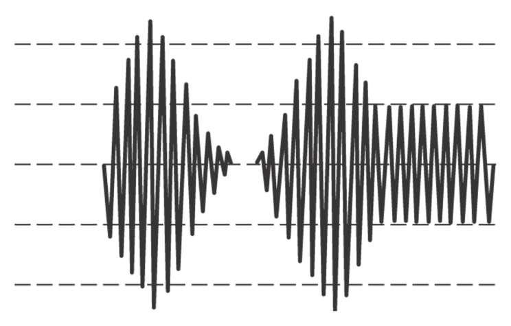
32 AM Waveforms 32
33 Equation of the AM Wave e = (E c + E i sinω i t)sinω c t E c = peak amplitude of carrier E i = peak amplitude of intelligence ω i t = radian frequency of intelligence ω c t = radian frequency of carrier ω = 2π 33
34 AM Analysis The instantaneous value of the AM waveform can be developed as follows. The equation for the amplitude of an AM waveform can be written as the carrier peak amplitude, Ec, plus the intelligence signal. We know, e i = E i sinω i t E = E c + e i E = E c + E i sin ω i t 34
35 AM Analysis Ratio of E i /E c = m =Modulation index E = E c + me c sin ω i t = E c (1 + m sin ω i t) The instantaneous value for the AM wave is the amplitude, E, times sinω c t e = E sin ω c t = E c (1 + m sin ω i t) sin ω c t 35
36 AM Analysis Remember the trigonometric identity : sin x sin y = ½[cos(x - y) cos(x + y)] We can write e as follows: e = E c sin ω c t + [m E c /2]cos(ω c - ω i )t [m E c /2]cos(ω c + ω i )t 36
37 Frequency Spectrum 37
38 The AM Waveform The three components that form the AM waveform are listed below: 1. The lower-side frequency (f c - f i ) 2. The carrier frequency (f c ) 3. The upper-side frequency (f c + f i ) 38
39 AM Waveforms 39

40 Carrier and Side Frequency Components 40
41 Upper and Lower Sidebands In most systems the intelligence signal is a complex waveform containing components from roughly 200Hz to 3KHz. If this is used to modulate the carrier there would be a whole band of side frequencies. The band of frequencies above the carrier is term the upper sideband. The band of frequencies below the carrier is called the lower sideband. 41
42 Upper and Lower Sidebands 42
43 Example A 1.4MHz carrier is modulated by a music signal that has frequency components from 20Hz to 10kHz. Determine the range of frequencies generated for the upper and lower sidebands. 43
44 Solution 44
45 Voltage (V) Voltage (V) Modulation index (m) The relationship between the modulating signal amplitude V m and the carrier V c is a ratio called the modulation index m defined as Sometimes m is expressed as a percentage percent modulation m100% 1.5 V m V m c m = 20% m = 50% m = 90% Time (sec) Time (sec) Time (sec)

46 Overmodulation m should range between 0 and 1. The condition in which m > 1 is called overmodulation and will result in distortion. 46
47 Voltage (V) Modulation index V c We can also determine the modulation index m from the maximum and minimum values of the envelope of v AM Vmax Vmin V m V m Modulating signal envelope V max V V m c 2 Vmax Vmin 2 V V V m max min m V c V max V min 0 V min
48 Voltage (V) Voltage (V) Voltage (V) Example Problem If a carrier signal with an amplitude of 9 V is mixed with a modulating signal with an amplitude of 7.5 V, what is the percentage modulation of the resulting 2 signal? V Time (sec) Time (sec) 9-V
49 Percentage Modulation A measure of the extent to which a carrier voltage is varied by the intelligent signal. Also known as modulation index or modulation factor and is symbolized by m. 0 m 1 0 => no modulation 1 => 100% modulation 49

50 AM Waveforms 50
51 Example An unmodulated carrier is 300V p-p. Calculate %m when its maximum p-p value reaches 400, 500,
52 Overmodulation When an excessive intelligent signal overdrives an AM modulator producing percentage modulation exceeding 100 percent. Overmodulation produces sideband splatter. Distortion resulting in an overmodulated AM transmission creating excessive bandwidths. 52
53 Overmodulation 53
54 Voltage (V) Voltage (V) Voltage (V) Voltage (V) Voltage (V) Voltage (V) AM in the frequency domain Time (sec) Information signal v m (for tuning fork f m = 440-Hz ) Frequency domain Frequency (Hz) Modulator or mixer Amplitude modulated signal v AM Time (sec) Frequency domain? Frequency (Hz) -1.5 Frequency domain Time (sec) Frequency (Hz) Carrier signal v c (carrier frequency f c = 5-kHz) 54
55 AM in the frequency domain v AM is given v ( V V sin 2 f t)sin 2 f t AM c m m c V sin 2 f t V sin 2 f t sin 2 f t c c m m c Applying the trigonometric identity for the product of two sine functions we can write sin A sin B cos( A B) cos( A B) 2 2 Vm Vm vam Vc sin 2 fct sin 2 ( fc fm) t sin 2 ( fc fm) t
56 Voltage (V) Voltage (V) AM in the frequency domain This form shows that v AM consists of just three frequency components. Vm Vm vam sin 2 ( fc fm) t Vc sin 2 fct sin 2 ( fc fm) t 2 2 Lower sideband f f f LSB c m Carrier frequency fc Upper sideband f f f USB c m Frequency domain f 5000 Hz c flsb fusb Hz 5440 Hz Time (sec) Amplitude modulated signal v AM Frequency (Hz) 56
57 Example Determine the maximum sideband power if the carrier output is 1 kw and calculate the total maximum transmitted power. 57
58 Solution Max sideband power occurs when m = 1 or 100%. At this percentage modulation each side frequency is ½ the carrier amplitude. E SF = me c /2 Since power is proportional to the square of the voltage, each has ¼ of the carrier power. ¼ x 1kW = 250W Total sideband power = 2 x 250 = 500W Total transmitted power = 1kW + 500W = 1.5kW 58
59 Importance of High Percentage Modulation It in important to use a high a percentage of modulation as possible while ensuring that overmodulation does not occur. The sidebands contain the information and have maximum power at 100% modulation. Useful equation P t = P c (1 + m 2 /2) P t = Total transmitted power (sidebands and carrier) P c = Carrier power 59
60 Importance of High Percentage Modulation I t = I c (1 + m 2 /2) I t I c m = Total transmitted current = Carrier current = Modulating index 60
61 Example 1. A 500W carrier is to be modulated to a 90% level. Determine the total transmitted power. 2. An AM broadcast station operates at its maximum allowed total output of 50kW and at 95% modulation. How much of its transmitted power is intelligence (sidebands)? 3. The antenna current of an AM transmitter is 12A when unmodulated but increase to 13A when modulated. Calculate %m. 61
62 Effective Modulation Index If a carrier is modulated by more than a single sine wave, the effective modulation index is given by: m eff = (m m m ) Note that the total modulation index must not exceed 1 or distortion will occur. m eff can be used in all previously developed equations using m. 62
63 Example A transmitter with a 10kW carrier transmit 11.2kW when modulated with a single sine wave. Calculate the modulation index. If the carrier is simultaneously modulated with another sine wave at 50 percent modulation, calculate the total transmitted power. 63

64 Baseband vs Passband Transmission Baseband signals: Voice (0-4kHz) TV (0-6 MHz) A signal may be sent in its baseband format when a dedicated wired channel is available. Otherwise, it must be converted to passband. 64
65 Types of Amplitude Modulation (AM) Double Sideband with carrier (we will call it AM): This is the most widely used type of AM modulation. In fact, all radio channels in the AM band use this type of modulation. Double Sideband Suppressed Carrier (DSBSC): This is the same as the AM modulation above but without the carrier. Single Sideband (SSB): In this modulation, only half of the signal of the DSBSC is used. Vestigial Sideband (VSB): This is a modification of the SSB to ease the generation and reception of the signal. 65
66 Double Sideband Suppressed Carrier (DSBSC) Assume that we have a message signal m(t) with bandwidth 2 B rad/s (or B Hz). m(t) M(). Let c(t) be a carrier signal, c(t) = cos( c t), c >> 2B g DSBSC (t) = m(t)cos( c t) (1/2) [M( c ) + M( + c )]. m(t) X g DSBSC (t) c(t) DSBSC Modulator (transmitter) 66
67 Time and Frequency Representation of DSBSC Modulation Process 67
68 DSBSC Demodulation g DSBSC (t) X e(t) H LPF () BW = 2B f(t) e (t)=g DSBSC (t)cos( c t) = m(t)cos 2 ( c t) = (1/2) m(t) [1 + cos(2 c t)] = (1/2) m(t) + (1/2) m(t) cos(2 c t) E() (1/2) M() + (1/4) [M( 2 c ) + M( + 2 c )]. The output signal f(t) of the LPF will be f (t) = (1/2) m(t) (1/2) M(). c(t) DSBSC Demodulator (receiver) 68
69 Time and Frequency Representation of DSBSC Demodulation Process 69
70 Modulator Circuits Basically we are after multiplying a signal with a carrier. There are three realizations of this operation: Multiplier Circuits Non-Linear Circuits Switching Circuits 70
71 Non-Linear Devices (NLD) A NLD is a device whose input-output relation is nonlinear. One such example is the diode (i D =e v D/v T ). The output of a NLD can be expressed as a power series of the input, that is y(t) = ax(t) + bx 2 (t) + cx 3 (t) + When x(t) << 1, the higher powers can be neglected, and the output can be approximated by the first two terms. When the input x(t) is the sum of two signal, m(t)+c(t), x 2 (t) will have the product term m(t)c(t) 71
72 Non-Linear Modulators m(t) c(t) + x 1 (t) Non-Linear Device a(. )+b(. ) 2 + z(t) HBPF () Cntr Freq. = C y 2 (t) BW = 4B x 2 (t) Non-Linear Device + a(. )+b(. ) 2 y 1 (t) q(t) x ( t) c( t) m( t) cos( t) m( t) 1 x ( t) c( t) m( t) cos( t) m( t) 1 z t) y ( t) y ( t) ( 1 2 2am( t) 4bm( t) cos( Ct) Undesired C C Desired DSBSC modulation using non-linear device y ( t) a 1 y ( t) a 2 cos( t) m( t) bcos( t) m( t) 2 am( t) bm ( t) 2bm( t) cos( Ct) a cos( Ct) Undesired cos( t) m( t) bcos( t) m( t) 2 am( t) bm ( t) 2bm( t) cos( Ct) a cos( Ct) Undesired C 2 a cos( t) am( t) bm ( t) 2bm( t) cos( t) bcos C C C Undesired Undesired Desired C C Desired C Undesired C Undesired b 2 Undesired 2 a cos( t) am( t) bm ( t) 2bm( t) cos( t) bcos b 2 Undesired ( t) C b cos(2ct) 2 ( t) C Undesired b cos(2ct) 2 Undesired 72
73 Switching Modulators Any periodic function can be expressed as a series of cosines (Fourier Series). The information signal, m(t), can therefore be, equivalently, multiplied by any periodic function, and followed by BPF. Let this periodic function be a train of pulses. Multiplication by a train of pulses can be realized by simple switching. 73
74 Switching Modulator Illustration 74
75 Switching Modulator: Diode Bridge 75
76 Switching Modulator: Ring 76
77 Demodulation of DSBSC The modulator circuits can be used for demodulation, but replacing the BPF by a LPF of bandwidth B Hz. The receiver must generate a carrier frequency in phase and frequency synchronization with the incoming carrier. This type of demodulation is therefore called coherent demodulation (or detection). g DSBSC (t) X e(t) H LPF () BW = 2B f(t) c(t) DSBSC Demodulator (receiver) 77
78 From DSBSC to DSBWC (AM) Carrier recovery circuits, which are required for the operation of coherent demodulation, are sophisticated and could be quite costly. If we can let m(t) be the envelope of the modulated signal, then a much simpler circuit, the envelope detector, can be used for demodulation (non-coherent demodulation). How can we make m(t) be the envelope of the modulated signal? 78
79 Definition of AM Shift m(t) by some DC value A such that A+m(t) 0. Or A m peak g AM ( t) [ A m( t)]cos( t) Acos( t) C C m( t)cos( t) C Called DSBWC. Here will refer to it as Full AM, or simply AM Modulation index m = m p /A. 0 m 1 79
80 Spectrum of AM g AM 1 ( t) A C C C C 2 ( ) ( ) M ( ) M ( ) 80
81 The Buy and Price of AM Buy: Simplicity in demodulation. Price: Waste in Power g AM (t) = Acos c t + m(t) cos c t Carrier Power P c = A 2 /2 (carries no information) Sideband Power P s = P m /2 (useful) Power efficiency = h = P s /(P c + P s )= P m /(A 2 +P m ) 81
82 Tone Modulation m(t) = Bcos( m t) g(t)=[a+ Bcos( m t)] cos c t = A[1+m cos( m t)] cos c t h = (B 2 /2)/(B 2 /2 + A 2 ) = m 2 /(2+m 2 ) Under best conditions, m=1 h max =1/3 =33% For m = 0.5, h = 11.11% For practical signals, h < 25%? Would you use AM or DSBSC? 82
83 Generation of AM AM signals can be generated by any DSBSC modulator, by using A+m(t) as input instead of m(t). In fact, the presence of the carrier term can make it even simpler. We can use it for switching instead of generating a local carrier. The switching action can be made by a single diode instead of a diode bridge. 83
84 AM Generator A >> m(t) (to ensure switching at every period). A m(t) cos( c t) R BPF v o (t) v R =[cos c t+m(t)][1/2 + 2/(cos c t-1/3cos3 c t + )+ =(1/2)cos c t+(2/m(t) cos c t + other terms (suppressed by BPF) v o (t) = (1/2)cos c t+(2/m(t) cos c t 84
85 AM Modulation Process (Frequency) 85
86 AM Demodulation: Rectifier Detector Because of the presence of a carrier term in the received signal, switching can be performed in the same way we did in the modulator. C [A+m(t)]cos( c t) LPF R m(t) 86
87 Rectifier Detector: Time Domain 87
88 Rectifier Detector (Frequency Domain) 88
89 Envelope Detector [A+m(t)]cos( c t) C R v o (t) When D is forward-biased, the capacitor charges and follows input. When D is reverse-biased, the capacitor discharges through R. 89
90 Envelope Detection The operations of the circuit requires careful selection of t=rc If RC is too large, discharging will be slow and the circuit cannot follow a decreasing envelope. When RC is too small the ripples will be high. 1/(2B) << t << 1/ c The ripples are finally removed by LPF. The DC value is blocked by a capacitor. 90
91 Quadrature Amplitude Modulation (QAM) In DSBSC or AM the modulated signal occupies double the bandwidth of the baseband signal. It is possible to send two signals over the same band, one modulated with a cosine and one with sine. Interesting enough, the two signals can be received separately after demodulation. 91
92 m 1 (t)cos 2 ( c t) + m 2 (t)sin( c t)cos( c t) =m 1 (t)/2+m 1 (t) cos(2 c t)/2 + m 2 (t)sin(2 c t)/2 IN-PHASE modulator branch Baseband Around c Around c m 1 (t) X m 1 (t)cos( c t) X H LPF () BW = 2B m 1 (t)/2 sin( c t) cos( c t) Phase Shifter /2 sin( c t) cos( c t) Phase Shifter /2 IN-PHASE demodulator branch QUADRATURE demodulator branch m 2 (t) X m 2 (t)sin( c t) X H LPF () BW = 2B m 2 (t)/2 QUADRATURE modulator branch m 1 (t)cos( c t) + m 2 (t)sin( c t) m 1 (t)sin( c t)cos( c t) + m 2 (t)sin 2 ( c t) =m 1 (t)sin(2 c t)/2 + m 2 (t)/2 m 2 (t)cos(2 c t)/2 Around c Baseband Around c QAM Modulator/Demodulator 92
93 m 1 (t)cos( c t)cos[( c +t+ + m 2 (t)sin( c t)cos[( c +t+ =(1/2)[m 1 (t)cos(t+) + m 1 (t) cos(2 c t+t+) m 2 (t)sin(t+) + m 2 (t)sin(2 c t+t+)] Baseband Around c Baseband Around c m 1 (t) X m 1 (t)cos( c t) X H LPF () BW = 2B (1/2)[m 1 (t)cos(t+) m 2 (t)sin(t+)] sin( c t) cos( c t) Phase Shifter /2 cos[( c +t+ Phase Shifter /2 sin[( c +t+ m 2 (t) X m 2 (t)sin( c t) X H LPF () BW = 2B (1/2)[m 1 (t)sin(t+) + m 2 (t)cos(t+)] m 1 (t)cos( c t) + m 2 (t)sin( c t) m 1 (t)cos( c t)sin[( c +t+ + m 2 (t)sin( c t)sin[( c +t+ =(1/2)[m 1 (t)sin(t+) + m 1 (t) sin(2 c t+t+) + m 2 (t)cos(t+) m 2 (t)cos(2 c t+t+)] Baseband Around c Baseband Around c QAM Modulator/Demodulator with Demodulator Carrier Phase and/or Frequency Error 93
94 Single-Side Band (SSB) Modulation DSBSC (as well as AM) occupies double the bandwidth of the baseband signal, although the two sides carry the same information. Why not send only one side, the upper or the lower? Modulation: similar to DSBSC. Only change the settings of the BPF (center frequency, bandwidth). Demodulation: similar to DSBSC (coherent) 94
95 SSB Representation How would we represent the SSB signal in the time domain? g USB (t) =? g LSB (t) =? 95
96 Time-Domain Representation of SSB (1/2) M() = M + () + M - () Let m + (t) M + () and m - (t) M - () Then: m(t) = m + (t) + m - (t) [linearity] Because M + (), M - () are not even m + (t), m - (t) are complex. Since their sum is real they must be conjugates. m + (t) = ½ [m(t) + j m h (t)] m - (t) = ½ [m(t) - j m h (t)] What is m h (t)? 96
97 Time-Domain Representation of SSB (2/2) M() = M + () + M - () M + () = M()u(; M - () = M()u(- sgn()=2u() -1 u()= ½ + ½ sgn(); u(-) = ½ -½ sgn() M + () = ½[ M() + M()sgn()] M - () = ½ [M() - M()sgn()] Comparing to: m + (t) = ½ [m(t) + j m h (t)+ ½ *M() + j M h ()] m - (t) = ½ [m(t) - j m h (t)+ ½ *M() - j M h ()] We find M h () = - j M() sgn() where m h (t) M h () 97
98 Hilbert Transform m h (t) is known as the Hilbert Transform (HT) of m(t). The transfer function of this transform is given by: H() = -j sgn() H() = 1 1 H() = jsgn() j j sgn /2 It is basically a /2 phase shifter /2 98
99 Hilbert Transform of cos( c t) cos( c t) ( c) + ( + c)] HT[cos( c t)+ -j sgn() ( c) + ( + c)] = j sgn() ( c) ( + c)] = j ( c) + ( + c)] = j ( + c) - ( - c)+ sin( c t) Which is expected since: cos( c t-/2) = sin( c t) 99
100 Time-Domain Operation for Hilbert Transformation For Hilbert Transformation H() = -j sgn(). What is h(t)? sgn(t) 2/(j) [From FT table] 2/(jt) 2 sgn(-) [symmetry] 1/( t) -j sgn() Since M h () = - j M() sgn() = H() M() Then m h ( t) 1 * m( t) t 1 m( ) d t 100
101 ) )sin( ( ) )cos( ( ) ( 2 1 ) ( 2 1 ) ( 2 1 ) ( 2 1 ) ( ) )sin( ( ) )cos( ( ) ( 2 1 ) ( 2 1 ) ( 2 1 ) ( 2 1 ) ( t t m t m t e t jm e m t e t jm e m t t g t t m t m t e t jm e m t e t jm e m t t g C h C t j h t j t j h t j LSB C h C t j h t j t j h t j USB C C C C C C C C ) ( ) ( ) ( ) ( ) ( ) ( C C LSB C C USB M M G M M G t j t j LSB t j t j USB C C C C e t m e t m t g e t m e t m t g ) ( ) ( ) ( ) ( ) ( ) ( Finally 101
102 Generation of SSB Selective Filtering Method Realization based on spectrum analysis Phase-Shift Method Realization based on time-domain expression of the modulated signal 102
103 Selective Filtering M() C 2B +2B C G DSBSC () USB LSB LSB USB C 2B C C +2B C 2B C C +2B M() (an example of an audio signal) Guard Band of 600 Hz C 2B C C +2B H USB () C 2B C C +2B BW = 2B (B Hz) Center Freq = c +B 5000 Hz 300 Hz 300 Hz 5000 Hz USB G USB () USB C 2B C C C +2B H LSB () BW = 2B (B Hz) Center Freq = c B C 2B C C +2B C 2B C C +2B G LSB () LSB LSB C C +2B C 2B C 103
104 Phase Shifting g g USB LSB ( t) ( t) m( t)cos( t) m C m( t)cos( t) m C h h ( t)sin( t) C ( t)sin( t) C X m(t)cos( c t) (a) m(t) sin( c t) cos( c t) Phase Shifter /2 + or (d) g USB (t) if g LSB (t) if + g SSB (t) Phase Shifter /2 (b) X (c) m h (t)sin( c t) m h (t) SSB Modulator 104
105 Phase-shifting Method: Frequency-Domain Illustration 105
106 SSB Demodulation (Coherent) g g SSB SSB ( t) ( t)cos( t) LPF Output m( t)cos( t) m C 1 2 C m( t) h ( t)sin( t) 1 m( t)[1 cos(2 Ct)] 2 C 1 2 m h ( t)sin(2 t) C g SSB (t) (Upper or Lower Side bands) X H LPF () BW = 2B m(t) cos( c t) SSB Demodulator (receiver) 106
107 FDM in Telephony FDM is done in stages Reduce number of carrier frequencies More practical realization of filters Group: 12 voice channels 4 khz = 48 khz occupy the band khz Supergroup: 5 groups 48 khz = 240 khz occupy the band Mastergroup: 10 S-G 240 khz = 2400 khz occupy the band khz 107
108 FDM Hierarchy Group 108 k 60 k Supergroup 552 k 312 k 108
109 Vestigial Side Band Modulation (VSB) What if we want to generate SSB using selective filtering but there is no guard band between the two sides? We will filter-in a vestige of the other band. Can we still recover our message, without distortion, after demodulation? Yes. If we use a proper LPF. 109
110 Filtering Condition of VSB g G G DSBSC DSBSC VSB ( t) 2m( t)cos( t) ( ) M( C ) M( C ) C ( ) HVSB ( ) M( C ) M( C X ( ) H VSB H VSB ( C ) M ( 2C ) M ( ) at 2C Baseband ) ( C ) M ( ) M ( 2 C ) baseband at 2C m(t) g VSB (t) H ( ) H ( ) M( ) Z( ) H ( ) H LPF LPF ( ) H VSB VSB C 1 ( ) H C VSB VSB C ( ) C X 2cos( c t) ; 2 B g DSBSC (t) H VSB () (BPF) VSB Modulator (transmitter) X 2cos( c t) x(t) H LPF () BW = 2B VSB Demodulator (receiver) g VSB (t) m(t) 110
111 VSB Filtering H VSB () C Shifted filter components C What happens outside the band of the demodulated signal is not important. So, the LPF does not have to inverse this part. H VSB ( c )+H VSB ( c ) Band of Signal H VSB ( c ) = 1/[H VSB ( c )+H VSB ( c )] over the band of the signal only Band of Signal 111
112 VSB Filter: Special Case Condition For distortionless demodulation: 1 H LPF ( ) ; 2 B HVSB ( C ) HVSB ( C ) If we impose the condition on the filter at the modulator: Then H VSB ( c ) + H VSB ( c ) = 1 ; 2 B H LPF = 1 for 2 B (Ideal LPF) H VSB () will then have odd symmetry around c over the transition period. 112
113 M() C 2B +2B C G DSBSC () C C H VSB () 2B (B Hz) < BW < 4B (2B Hz) C C G VSB () C C X() C C C C H LPF () C C M() 113 C C
114 AM Broadcasting Allocated the band 530 khz 1600 khz (with minor variations) 10 khz per channel. (9 khz in some countries) More that 100 stations can be licensed in the same geographical area. Uses AM modulation (DSB + C) 114
115 AM station Reception In theory, any station can be extracted from the stream of spectra by tuning the receiver BPF to its center frequency. Then demodulated. Impracticalities: Requires a BPF with very high Q-factor (Q = f c / B). Particularly difficult if the filter is to be tunable. 115
116 Solution: Superheterodyne receiver Step 1: Frequency Translation from RF to IF Shift the desired station to another fixed pass band (called Intermediate Frequency IF = 455 khz) Step 2: Bandpass Filtering at IF Build a good BPF around IF to extract the desired station. It is more practical now, because IF is relatively low (reasonable Q) and the filter is not tunable. Step 3: Demodulation Use Envelope Detector 116
117 117
118 The Local Oscillator What should be the frequency of the local oscillator used for translation from RF to IF? f LO = f c + f IF (up-conversion) or f LO = f c f IF (down-conversion) Tuning ratio = f LO, max / f LO, min Up-Conversion: ( ) / ( ) 2 Down-Conversion: ( ) / ( ) 12 Easier to design oscillator with small tuning ratio. 118
119 Image Station Problem While up-converting the desired station to IF, we are, at the same time, down-converting another station to IF as well. These two stations are called image stations, and they are spaced by 2x455=910kHz. Solution: Before conversion, use a BPF (at RF) centered at f c of the desired station. The purpose of the filter is NOT to extract the desired station, but to suppress its image. Hence, it does not have to be very sharp. 119
120 Superheterodyne Receiver Block Diagram Antenna RF Stage Converter (Multiplier) X IF Stage a(t) (radio frequency) b(t) d(t) (intermediate frequency) e(t) f(t) g(t) RF Amplifier & RF BPF c(t) IF Amplifier & IF BPF Envelope Detector Diode, Capacitor, Resistor, & DC blocker Audio Stage Power amplifier Ganged RF BPF and Oscillator Local Oscillator cos[( c + IF )t] Notes: With one knob, we are tuning the RF Filter and the local oscillator. The filter are designed with high gain to provide amplification as well. 120
121 121
122 122

123 Multiplexing -Multiplexing: Simultaneous transmission of multiple signals across a single data link. -In a multiplexed system, n lines share the bandwidth of one link. Dividing a link into channels - Link: The physical path. - Channel: Portion of link that carries a transmission between a pair of lines. - One link can have many (n) channels. 123
124 FDM (Frequency-division multiplexing) Categories of multiplexing 124

125 FDM (Frequency-division multiplexing) FDM - Channels must be separated by guard band to prevent signals from overlapping. - Carrier frequencies must not interfere with the original data frequencies. 125

126 FDM (Frequency-division multiplexing)c (1) Multiplexing Process FDM process - Each telephone generates a signal of similar frequency range. - Signals are modulated onto different carrier frequencies(f 1, f 2 and f 3 ). 126

127 FDM (Frequency-division multiplexing) (2) Demultiplexing Process - Demultiplexer uses a series of filters to decompose the multiplexed signal. FDM demultiplexing example 127
128 Example 1 FDM (Frequency-division multiplexing) Assume that a voice channel occupies a bandwidth of 4 KHz. We need to combine three voice channels into a link with a bandwidth of 12 KHz, from 20 to 32 KHz. Show the configuration using the frequency domain without the use of guard bands. Solution Shift (modulate) each of the three voice channels to a different bandwidth, as shown in Figure
129 FDM (Frequency-division multiplexing) 129
130 Example 2 FDM (Frequency-division multiplexing) Five channels, each with a 100-KHz bandwidth, are to be multiplexed together. What is the minimum bandwidth of the link if there is a need for a guard band of 10 KHz between the channels to prevent interference? Solution For five channels, we need at least four guard bands. This means that the required bandwidth is at least = 540 KHz, as shown in Figure
 Example 2")
131 FDM (Frequency-division multiplexing) Example 2 131
132 Example 3 FDM (Frequency-division multiplexing) Four data channels (digital), each transmitting at 1 Mbps, use a satellite channel of 1 MHz. Design an appropriate configuration using FDM Solution The satellite channel is analog. We divide it into four channels, each channel having a 250-KHz bandwidth. Each digital channel of 1 Mbps is modulated such that each 4 bits are modulated to 1 Hz. One solution is 16-QAM modulation. Figure 6.8 shows one possible configuration. 132
 Example 3")
133 FDM (Frequency-division multiplexing) Example 3 133
Speech, music, images, and video are examples of analog signals. Each of these signals is characterized by its bandwidth, dynamic range, and the
 Speech, music, images, and video are examples of analog signals. Each of these signals is characterized by its bandwidth, dynamic range, and the nature of the signal. For instance, in the case of audio
AM Limitations. Amplitude Modulation II. DSB-SC Modulation. AM Modifications
 Lecture 6: Amplitude Modulation II EE 3770: Communication Systems AM Limitations AM Limitations DSB-SC Modulation SSB Modulation VSB Modulation Lecture 6 Amplitude Modulation II Amplitude modulation is
Amplitude Modulation II
 Lecture 6: Amplitude Modulation II EE 3770: Communication Systems Lecture 6 Amplitude Modulation II AM Limitations DSB-SC Modulation SSB Modulation VSB Modulation Multiplexing Mojtaba Vaezi 6-1 Contents
Amplitude Modulated Systems
 Amplitude Modulated Systems Communication is process of establishing connection between two points for information exchange. Channel refers to medium through which message travels e.g. wires, links, or
Amplitude Modulation, II
 Amplitude Modulation, II Single sideband modulation (SSB) Vestigial sideband modulation (VSB) VSB spectrum Modulator and demodulator NTSC TV signsals Quadrature modulation Spectral efficiency Modulator
CHAPTER 2! AMPLITUDE MODULATION (AM)
") CHAPTER 2 AMPLITUDE MODULATION (AM) Topics 2-1 : AM Concepts 2-2 : Modulation Index and Percentage of Modulation 2-3 : Sidebands and the Frequency Domain 2-4 : Single-Sideband Modulation 2-5 : AM Power
CHAPTER 2 AMPLITUDE MODULATION (AM) Topics 2-1 : AM Concepts 2-2 : Modulation Index and Percentage of Modulation 2-3 : Sidebands and the Frequency Domain 2-4 : Single-Sideband Modulation 2-5 : AM Power
Amplitude Modulation. Ahmad Bilal
 Amplitude Modulation Ahmad Bilal 5-2 ANALOG AND DIGITAL Analog-to-analog conversion is the representation of analog information by an analog signal. Topics discussed in this section: Amplitude Modulation
Outline. Communications Engineering 1
 Outline Introduction Signal, random variable, random process and spectra Analog modulation Analog to digital conversion Digital transmission through baseband channels Signal space representation Optimal
Chapter 3. Amplitude Modulation Fundamentals
 Chapter 3 Amplitude Modulation Fundamentals Topics Covered 3-1: AM Concepts 3-2: Modulation Index and Percentage of Modulation 3-3: Sidebands and the Frequency Domain 3-4: AM Power 3-5: Single-Sideband
 Modulations Analog Modulations Amplitude modulation (AM) Linear modulation Frequency modulation (FM) Phase modulation (PM) cos Angle modulation FM PM Digital Modulations ASK FSK PSK MSK MFSK QAM PAM Etc.
4- Single Side Band (SSB)
") 4- Single Side Band (SSB) It can be shown that: s(t) S.S.B = m(t) cos ω c t ± m h (t) sin ω c t -: USB ; +: LSB m(t) X m(t) cos ω c t -π/ cos ω c t -π/ + s S.S.B m h (t) X m h (t) ± sin ω c t 1 Tone Modulation:
4- Single Side Band (SSB) It can be shown that: s(t) S.S.B = m(t) cos ω c t ± m h (t) sin ω c t -: USB ; +: LSB m(t) X m(t) cos ω c t -π/ cos ω c t -π/ + s S.S.B m h (t) X m h (t) ± sin ω c t 1 Tone Modulation:
UNIT I AMPLITUDE MODULATION
 UNIT I AMPLITUDE MODULATION Prepared by: S.NANDHINI, Assistant Professor, Dept. of ECE, Sri Venkateswara College of Engineering, Sriperumbudur, Tamilnadu. CONTENTS Introduction to communication systems
! Amplitude of carrier wave varies a mean value in step with the baseband signal m(t)
") page 7.1 CHAPTER 7 AMPLITUDE MODULATION Transmit information-bearing (message) or baseband signal (voice-music) through a Communications Channel Baseband = band of frequencies representing the original
page 7.1 CHAPTER 7 AMPLITUDE MODULATION Transmit information-bearing (message) or baseband signal (voice-music) through a Communications Channel Baseband = band of frequencies representing the original
Introduction to Amplitude Modulation
 1 Introduction to Amplitude Modulation Introduction to project management. Problem definition. Design principles and practices. Implementation techniques including circuit design, software design, solid
UNIT-I AMPLITUDE MODULATION (2 Marks Questions and Answers)
") UNIT-I AMPLITUDE MODULATION (2 Marks Questions and Answers) 1. Define modulation? Modulation is a process by which some characteristics of high frequency carrier Signal is varied in accordance with the
UNIT-I AMPLITUDE MODULATION (2 Marks Questions and Answers) 1. Define modulation? Modulation is a process by which some characteristics of high frequency carrier Signal is varied in accordance with the
Elements of Communication System Channel Fig: 1: Block Diagram of Communication System Terminology in Communication System
 Content:- Fundamentals of Communication Engineering : Elements of a Communication System, Need of modulation, electromagnetic spectrum and typical applications, Unit V (Communication terminologies in communication
Charan Langton, Editor
 Charan Langton, Editor SIGNAL PROCESSING & SIMULATION NEWSLETTER Baseband, Passband Signals and Amplitude Modulation The most salient feature of information signals is that they are generally low frequency.
Problems from the 3 rd edition
 (2.1-1) Find the energies of the signals: a) sin t, 0 t π b) sin t, 0 t π c) 2 sin t, 0 t π d) sin (t-2π), 2π t 4π Problems from the 3 rd edition Comment on the effect on energy of sign change, time shifting
Communications and Signals Processing
 Communications and Signals Processing Department of Communications An Najah National University 2012/2013 1 3.1 Amplitude Modulation 3.2 Virtues, Limitations, and Modifications of Amplitude Modulation
Communication Channels
 Communication Channels wires (PCB trace or conductor on IC) optical fiber (attenuation 4dB/km) broadcast TV (50 kw transmit) voice telephone line (under -9 dbm or 110 µw) walkie-talkie: 500 mw, 467 MHz
B.Tech II Year II Semester (R13) Supplementary Examinations May/June 2017 ANALOG COMMUNICATION SYSTEMS (Electronics and Communication Engineering)
 Supplementary Examinations May/June 2017 ANALOG COMMUNICATION SYSTEMS (Electronics and Communication Engineering)") Code: 13A04404 R13 B.Tech II Year II Semester (R13) Supplementary Examinations May/June 2017 ANALOG COMMUNICATION SYSTEMS (Electronics and Communication Engineering) Time: 3 hours Max. Marks: 70 PART A
Code: 13A04404 R13 B.Tech II Year II Semester (R13) Supplementary Examinations May/June 2017 ANALOG COMMUNICATION SYSTEMS (Electronics and Communication Engineering) Time: 3 hours Max. Marks: 70 PART A
Amplitude Modulation Early Radio EE 442 Spring Semester Lecture 6
 Amplitude Modulation Early Radio EE 442 Spring Semester Lecture 6 f f f LO audio baseband m http://www.technologyuk.net/telecommunications/telecom_principles/amplitude_modulation.shtml AM Modulation --
Chapter 5. Amplitude Modulation
 Chapter 5 Amplitude Modulation So far we have developed basic signal and system representation techniques which we will now apply to the analysis of various analog communication systems. In particular,
Code No: R Set No. 1
 Code No: R05220405 Set No. 1 II B.Tech II Semester Regular Examinations, Apr/May 2007 ANALOG COMMUNICATIONS ( Common to Electronics & Communication Engineering and Electronics & Telematics) Time: 3 hours
Master Degree in Electronic Engineering
 Master Degree in Electronic Engineering Analog and telecommunication electronic course (ATLCE-01NWM) Miniproject: Baseband signal transmission techniques Name: LI. XINRUI E-mail: s219989@studenti.polito.it
COMM 601: Modulation I
 Prof. Ahmed El-Mahdy, Communications Department The German University in Cairo Text Books [1] Couch, Digital and Analog Communication Systems, 7 th edition, Prentice Hall, 2007. [2] Simon Haykin, Communication
4.1 REPRESENTATION OF FM AND PM SIGNALS An angle-modulated signal generally can be written as
 1 In frequency-modulation (FM) systems, the frequency of the carrier f c is changed by the message signal; in phase modulation (PM) systems, the phase of the carrier is changed according to the variations
(b) What are the differences between FM and PM? (c) What are the differences between NBFM and WBFM? [9+4+3]
![(b) What are the differences between FM and PM? (c) What are the differences between NBFM and WBFM? [9+4+3]](/thumbs/85/91561193.jpg "(b) What are the differences between FM and PM? (c) What are the differences between NBFM and WBFM? [9+4+3]") Code No: RR220401 Set No. 1 1. (a) The antenna current of an AM Broadcast transmitter is 10A, if modulated to a depth of 50% by an audio sine wave. It increases to 12A as a result of simultaneous modulation
Code No: RR220401 Set No. 1 1. (a) The antenna current of an AM Broadcast transmitter is 10A, if modulated to a depth of 50% by an audio sine wave. It increases to 12A as a result of simultaneous modulation
3.1 Introduction to Modulation
 Haberlesme Sistemlerine Giris (ELE 361) 9 Eylul 2017 TOBB Ekonomi ve Teknoloji Universitesi, Guz 2017-18 Dr. A. Melda Yuksel Turgut & Tolga Girici Lecture Notes Chapter 3 Amplitude Modulation Speech, music,
Radio Technology and Architectures. 1 ENGN4521/ENGN6521: Embedded Wireless L#1
 Radio Technology and Architectures 1 ENGN4521/ENGN6521: Embedded Wireless L#1 Radio (Architectures) Spectrum plan and legal issues Radio Architectures and components 2 ENGN4521/ENGN6521: Embedded Wireless
Description of the AM Superheterodyne Radio Receiver
 Superheterodyne AM Radio Receiver Since the inception of the AM radio, it spread widely due to its ease of use and more importantly, it low cost. The low cost of most AM radios sold in the market is due
Data Conversion Circuits & Modulation Techniques. Subhasish Chandra Assistant Professor Department of Physics Institute of Forensic Science, Nagpur
 Data Conversion Circuits & Modulation Techniques Subhasish Chandra Assistant Professor Department of Physics Institute of Forensic Science, Nagpur Data Conversion Circuits 2 Digital systems are being used
3.1 Introduction 3.2 Amplitude Modulation 3.3 Double Sideband-Suppressed Carrier Modulation 3.4 Quadrature-Carrier Multiplexing 3.
 Chapter 3 Amplitude Modulation Wireless Information Transmission System Lab. Institute of Communications Engineering g National Sun Yat-sen University Outline 3.1 Introduction 3. Amplitude Modulation 3.3
Problem Sheet for Amplitude Modulation
 Problem heet for Amplitude Modulation Q1: For the sinusoidaly modulated DB/LC waveform shown in Fig. below. a Find the modulation index. b ketch a line spectrum. c Calculated the ratio of average power
Twelve voice signals, each band-limited to 3 khz, are frequency -multiplexed using 1 khz guard bands between channels and between the main carrier
 Twelve voice signals, each band-limited to 3 khz, are frequency -multiplexed using 1 khz guard bands between channels and between the main carrier and the first channel. The modulation of the main carrier
LAB Assignment No. 6: TO STUDY GENERATION OF DOUBLE SIDE BAND AMPLITUDE MODULATE (AM) WAVEFORMS, USING DSB/SSB TRANSMITTER
 WAVEFORMS, USING DSB/SSB TRANSMITTER") LAB Assignment No. 6: TO STUDY GENERATION OF DOUBLE SIDE BAND AMPLITUDE MODULATE (AM) WAVEFORMS, USING DSB/SSB TRANSMITTER APPARATUS: Oscilloscope DSB/SSB Traine Power supply Connecting leads THEORY: A
LAB Assignment No. 6: TO STUDY GENERATION OF DOUBLE SIDE BAND AMPLITUDE MODULATE (AM) WAVEFORMS, USING DSB/SSB TRANSMITTER APPARATUS: Oscilloscope DSB/SSB Traine Power supply Connecting leads THEORY: A
Wireless Communication Fading Modulation
 EC744 Wireless Communication Fall 2008 Mohamed Essam Khedr Department of Electronics and Communications Wireless Communication Fading Modulation Syllabus Tentatively Week 1 Week 2 Week 3 Week 4 Week 5
Amplitude Modulation Chapter 2. Modulation process
 Question 1 Modulation process Modulation is the process of translation the baseband message signal to bandpass (modulated carrier) signal at frequencies that are very high compared to the baseband frequencies.
Lecture 6. Angle Modulation and Demodulation
 Lecture 6 and Demodulation Agenda Introduction to and Demodulation Frequency and Phase Modulation Angle Demodulation FM Applications Introduction The other two parameters (frequency and phase) of the carrier
Amplitude Modulation Fundamentals
 3 chapter Amplitude Modulation Fundamentals In the modulation process, the baseband voice, video, or digital signal modifies another, higher-frequency signal called the carrier, which is usually a sine
Signals and Systems Lecture 9 Communication Systems Frequency-Division Multiplexing and Frequency Modulation (FM)
") Signals and Systems Lecture 9 Communication Systems Frequency-Division Multiplexing and Frequency Modulation (FM) April 11, 2008 Today s Topics 1. Frequency-division multiplexing 2. Frequency modulation
Signals and Systems Lecture 9 Communication Systems Frequency-Division Multiplexing and Frequency Modulation (FM) April 11, 2008 Today s Topics 1. Frequency-division multiplexing 2. Frequency modulation
OBJECTIVES EQUIPMENT LIST
 1 Reception of Amplitude Modulated Signals AM Demodulation OBJECTIVES The purpose of this experiment is to show how the amplitude-modulated signals are demodulated to obtain the original signal. Also,
DT Filters 2/19. Atousa Hajshirmohammadi, SFU
 1/19 ENSC380 Lecture 23 Objectives: Signals and Systems Fourier Analysis: Discrete Time Filters Analog Communication Systems Double Sideband, Sub-pressed Carrier Modulation (DSBSC) Amplitude Modulation
ELEC3242 Communications Engineering Laboratory Amplitude Modulation (AM)
") ELEC3242 Communications Engineering Laboratory 1 ---- Amplitude Modulation (AM) 1. Objectives 1.1 Through this the laboratory experiment, you will investigate demodulation of an amplitude modulated (AM)
ELEC3242 Communications Engineering Laboratory 1 ---- Amplitude Modulation (AM) 1. Objectives 1.1 Through this the laboratory experiment, you will investigate demodulation of an amplitude modulated (AM)
Vestigial Sideband Modulation KEEE343 Communication Theory Lecture #11, April 7, Prof. Young-Chai Ko
 Vestigial Sideband Modulation KEEE343 Communication Theory Lecture #11, April 7, 2011 Prof. Young-Chai Ko koyc@korea.ac.kr Summary Vestigial sideband modulation Baseband representation of modulated wave
EE4512 Analog and Digital Communications Chapter 6. Chapter 6 Analog Modulation and Demodulation
 Chapter 6 Analog Modulation and Demodulation Chapter 6 Analog Modulation and Demodulation Amplitude Modulation Pages 306-309 309 The analytical signal for double sideband, large carrier amplitude modulation
DIGITAL COMMUNICATIONS SYSTEMS. MSc in Electronic Technologies and Communications
 DIGITAL COMMUNICATIONS SYSTEMS MSc in Electronic Technologies and Communications Bandpass binary signalling The common techniques of bandpass binary signalling are: - On-off keying (OOK), also known as
INTRODUCTION TO COMMUNICATION SYSTEMS AND TRANSMISSION MEDIA
 COMM.ENG INTRODUCTION TO COMMUNICATION SYSTEMS AND TRANSMISSION MEDIA 9/9/2017 LECTURES 1 Objectives To give a background on Communication system components and channels (media) A distinction between analogue
Lecture 12 - Analog Communication (II)
") Lecture 12 - Analog Communication (II) James Barnes (James.Barnes@colostate.edu) Spring 2014 Colorado State University Dept of Electrical and Computer Engineering ECE423 1 / 12 Outline QAM: quadrature
Lecture 12 - Analog Communication (II) James Barnes (James.Barnes@colostate.edu) Spring 2014 Colorado State University Dept of Electrical and Computer Engineering ECE423 1 / 12 Outline QAM: quadrature
Communication Engineering Prof. Surendra Prasad Department of Electrical Engineering Indian Institute of Technology, Delhi
 Communication Engineering Prof. Surendra Prasad Department of Electrical Engineering Indian Institute of Technology, Delhi Lecture - 10 Single Sideband Modulation We will discuss, now we will continue
Chapter-15. Communication systems -1 mark Questions
 Chapter-15 Communication systems -1 mark Questions 1) What are the three main units of a Communication System? 2) What is meant by Bandwidth of transmission? 3) What is a transducer? Give an example. 4)
Internal Examination I Answer Key DEPARTMENT OF CSE & IT. Semester: III Max.Marks: 100
 NH 67, Karur Trichy Highways, Puliyur C.F, 639 114 Karur District Internal Examination I Answer Key DEPARTMENT OF CSE & IT Branch & Section: II CSE & IT Date & Time: 06.08.15 & 3 Hours Semester: III Max.Marks:
YEDITEPE UNIVERSITY ENGINEERING FACULTY COMMUNICATION SYSTEMS LABORATORY EE 354 COMMUNICATION SYSTEMS
 YEDITEPE UNIVERSITY ENGINEERING FACULTY COMMUNICATION SYSTEMS LABORATORY EE 354 COMMUNICATION SYSTEMS EXPERIMENT 3: SAMPLING & TIME DIVISION MULTIPLEX (TDM) Objective: Experimental verification of the
Chapter 3: Analog Modulation Cengage Learning Engineering. All Rights Reserved.
 Contemporary Communication Systems using MATLAB Chapter 3: Analog Modulation 2013 Cengage Learning Engineering. All Rights Reserved. 3.1 Preview In this chapter we study analog modulation & demodulation,
RADIO RECEIVERS ECE 3103 WIRELESS COMMUNICATION SYSTEMS
 RADIO RECEIVERS ECE 3103 WIRELESS COMMUNICATION SYSTEMS FUNCTIONS OF A RADIO RECEIVER The main functions of a radio receiver are: 1. To intercept the RF signal by using the receiver antenna 2. Select the
ECE5713 : Advanced Digital Communications
 ECE5713 : Advanced Digital Communications Bandpass Modulation MPSK MASK, OOK MFSK 04-May-15 Advanced Digital Communications, Spring-2015, Week-8 1 In-phase and Quadrature (I&Q) Representation Any bandpass
Chapter 5 AM Receivers
 Chapter 5 AM Receivers Prepared by Prof.V.K.Jain 1 Lecture outcome After studying this lecture, you should be able to: Describe the basic superheterodyne system Choose suitable intermediate frequencies
Amplitude Modulation. Amplitude Modulation. Amplitude Modulation. Amplitude Modulation. A. Introduction. A. Introduction
 1. In AM modulation we impart the information of a message signal m(t) on to a sinusoidal carrier c(t). This results in the translation of the message signal to a new frequency range. The motivation for
SAMPLE. UEENEEH046B Solve fundamental problems in electronic communications systems. Learner Workbook. UEE07 Electrotechnology Training Package
 UEE07 Electrotechnology Training Package UEENEEH046B Solve fundamental problems in electronic communications systems Learner Workbook Version 1 Training and Education Support Industry Skills Unit Meadowbank
S.E. (Electronics/Electronics and Telecommunication Engg.) (Second Semester) EXAMINATION, 2014 COMMUNICATION THEORY (2008 PATTERN)
 (Second Semester) EXAMINATION, 2014 COMMUNICATION THEORY (2008 PATTERN)") Total No. of Questions 12] [Total No. of Printed Pages 7 Seat No. [4657]-49 S.E. (Electronics/Electronics and Telecommunication Engg.) (Second Semester) EXAMINATION, 2014 COMMUNICATION THEORY (2008 PATTERN)
Total No. of Questions 12] [Total No. of Printed Pages 7 Seat No. [4657]-49 S.E. (Electronics/Electronics and Telecommunication Engg.) (Second Semester) EXAMINATION, 2014 COMMUNICATION THEORY (2008 PATTERN)
Linear Modulation: Amplitude Modulation
 1 Communication Systems Chapter Linear Modulation: Amplitude Modulation In the previous chapter, we have covered, what is modulation, its different types along with its need. Now here in this chapter we
UNIT-2 Angle Modulation System
 UNIT-2 Angle Modulation System Introduction There are three parameters of a carrier that may carry information: Amplitude Frequency Phase Frequency Modulation Power in an FM signal does not vary with modulation
Signal Characteristics
 Data Transmission The successful transmission of data depends upon two factors:» The quality of the transmission signal» The characteristics of the transmission medium Some type of transmission medium
Receiver Design. Prof. Tzong-Lin Wu EMC Laboratory Department of Electrical Engineering National Taiwan University 2011/2/21
 Receiver Design Prof. Tzong-Lin Wu EMC Laboratory Department of Electrical Engineering National Taiwan University 2011/2/21 MW & RF Design / Prof. T. -L. Wu 1 The receiver mush be very sensitive to -110dBm
HF Receivers, Part 2
 HF Receivers, Part 2 Superhet building blocks: AM, SSB/CW, FM receivers Adam Farson VA7OJ View an excellent tutorial on receivers NSARC HF Operators HF Receivers 2 1 The RF Amplifier (Preamp)! Typical
FDM- FREQUENCY DIVISION MULTIPLEXING
 FDM- FREQUENCY DIVISION MULTIPLEXING Multiplexing to refer to the combination of information streams from multiple sources for transmission over a shared medium Demultiplexing to refer to the separation
Technician License Course Chapter 3 Types of Radios and Radio Circuits. Module 7
 Technician License Course Chapter 3 Types of Radios and Radio Circuits Module 7 Radio Block Diagrams Radio Circuits can be shown as functional blocks connected together. Knowing the description of common
 UNIT I FUNDAMENTALS OF ANALOG COMMUNICATION Introduction In the Microbroadcasting services, a reliable radio communication system is of vital importance. The swiftly moving operations of modern communities
The quality of the transmission signal The characteristics of the transmission medium. Some type of transmission medium is required for transmission:
 Data Transmission The successful transmission of data depends upon two factors: The quality of the transmission signal The characteristics of the transmission medium Some type of transmission medium is
AM and FM MODULATION Lecture 5&6
 AM and FM MODULATION Lecture 5&6 Ir. Muhamad Asvial, MEng., PhD Center for Information and Communication Engineering Research Electrical Engineering Department University of Indonesia Kampus UI Depok,
Chapter 7. Multiple Division Techniques
 Chapter 7 Multiple Division Techniques 1 Outline Frequency Division Multiple Access (FDMA) Division Multiple Access (TDMA) Code Division Multiple Access (CDMA) Comparison of FDMA, TDMA, and CDMA Walsh
ANALOG COMMUNICATION
 ANALOG COMMUNICATION TRAINING LAB Analog Communication Training Lab consists of six kits, one each for Modulation (ACL-01), Demodulation (ACL-02), Modulation (ACL-03), Demodulation (ACL-04), Noise power
EE3723 : Digital Communications
 EE3723 : Digital Communications Week 8-9: Bandpass Modulation MPSK MASK, OOK MFSK 04-May-15 Muhammad Ali Jinnah University, Islamabad - Digital Communications - EE3723 1 In-phase and Quadrature (I&Q) Representation
6. Modulation and Multiplexing Techniques
 6. Modulation and Multiplexing Techniques The quality of analog transmission is S/N (signal to noise ratio). signal power S/N = ---------------------------- baseband noise power S/N can be greater than
Lecture Fundamentals of Data and signals
 IT-5301-3 Data Communications and Computer Networks Lecture 05-07 Fundamentals of Data and signals Lecture 05 - Roadmap Analog and Digital Data Analog Signals, Digital Signals Periodic and Aperiodic Signals
RF/IF Terminology and Specs
 RF/IF Terminology and Specs Contributors: Brad Brannon John Greichen Leo McHugh Eamon Nash Eberhard Brunner 1 Terminology LNA - Low-Noise Amplifier. A specialized amplifier to boost the very small received
Outline / Wireless Networks and Applications Lecture 3: Physical Layer Signals, Modulation, Multiplexing. Cartoon View 1 A Wave of Energy
 Outline 18-452/18-750 Wireless Networks and Applications Lecture 3: Physical Layer Signals, Modulation, Multiplexing Peter Steenkiste Carnegie Mellon University Spring Semester 2017 http://www.cs.cmu.edu/~prs/wirelesss17/
Lecture-3 Amplitude Modulation: Single Side Band (SSB) Modulation
 Modulation") Lecture-3 Amplitude Modulation: Single Side Band (SSB) Modulation 3.0 Introduction. 3.1 Baseband Signal SSB Modulation. 3.1.1 Frequency Domain Description. 3.1. Time Domain Description. 3. Single Tone
Lecture-3 Amplitude Modulation: Single Side Band (SSB) Modulation 3.0 Introduction. 3.1 Baseband Signal SSB Modulation. 3.1.1 Frequency Domain Description. 3.1. Time Domain Description. 3. Single Tone
Modulation is the process of impressing a low-frequency information signal (baseband signal) onto a higher frequency carrier signal
 onto a higher frequency carrier signal") Modulation is the process of impressing a low-frequency information signal (baseband signal) onto a higher frequency carrier signal Modulation is a process of mixing a signal with a sinusoid to produce
Modulation is the process of impressing a low-frequency information signal (baseband signal) onto a higher frequency carrier signal Modulation is a process of mixing a signal with a sinusoid to produce
NEW YORK CITY COLLEGE of TECHNOLOGY THE CITY UNIVERSITY OF NEW YORK DEPARTMENT OF ELECTRICAL ENGINEERING AND TELECOMMUNICATIONS TECHNOLOGIES
 NEW YORK CITY COLLEGE of TECHNOLOGY THE CITY UNIVERSITY OF NEW YORK DEPARTMENT OF ELECTRICAL ENGINEERING AND TELECOMMUNICATIONS TECHNOLOGIES Course : EET 24 Communications Electronics Module : AM Tx and
Angle Modulated Systems
 Angle Modulated Systems Angle of carrier signal is changed in accordance with instantaneous amplitude of modulating signal. Two types Frequency Modulation (FM) Phase Modulation (PM) Use Commercial radio
Digital Communication System
 Digital Communication System Purpose: communicate information at required rate between geographically separated locations reliably (quality) Important point: rate, quality spectral bandwidth, power requirements
TSEK02: Radio Electronics Lecture 8: RX Nonlinearity Issues, Demodulation. Ted Johansson, EKS, ISY
 TSEK02: Radio Electronics Lecture 8: RX Nonlinearity Issues, Demodulation Ted Johansson, EKS, ISY RX Nonlinearity Issues: 2.2, 2.4 Demodulation: not in the book 2 RX nonlinearities System Nonlinearity
Modulation. Digital Data Transmission. COMP476 Networked Computer Systems. Analog and Digital Signals. Analog and Digital Examples.
 Digital Data Transmission Modulation Digital data is usually considered a series of binary digits. RS-232-C transmits data as square waves. COMP476 Networked Computer Systems Analog and Digital Signals
CSCD 433 Network Programming Fall Lecture 5 Physical Layer Continued
 CSCD 433 Network Programming Fall 2016 Lecture 5 Physical Layer Continued 1 Topics Definitions Analog Transmission of Digital Data Digital Transmission of Analog Data Multiplexing 2 Different Types of
Introduction to Telecommunications and Computer Engineering Unit 3: Communications Systems & Signals
 Introduction to Telecommunications and Computer Engineering Unit 3: Communications Systems & Signals Syedur Rahman Lecturer, CSE Department North South University syedur.rahman@wolfson.oxon.org Acknowledgements
Review of Spectral Characteristics of Periodic and Aperiodic signals-generation and
 CHETTINAD COLLEGE OF ENGINEERING & TECHNOLOGY DEPARTMENT OF ELECTRONICS AND COMMUNICATION ENGINEERING Faculty Name: Ms.P.Nalini Class/Sem : II Year / IV Sem Subject Name: Communication Theory Subject code:
Fourier Transform And Its Application In Modulation Techniques
 ourier Transform And Its Application In Modulation Techniques Mrs. Supriya Nilesh Thakur Mrs. Megha Kishor Kothawade Assistant Professor, Basic Engineering Science Department, Guru Gobind Singh College
PRINCIPLES OF COMMUNICATION SYSTEMS. Lecture 1- Introduction Elements, Modulation, Demodulation, Frequency Spectrum
 PRINCIPLES OF COMMUNICATION SYSTEMS Lecture 1- Introduction Elements, Modulation, Demodulation, Frequency Spectrum Topic covered Introduction to subject Elements of Communication system Modulation General
CHAPTER -15. Communication Systems
 CHAPTER -15 Communication Systems COMMUNICATION Communication is the act of transmission and reception of information. COMMUNICATION SYSTEM: A system comprises of transmitter, communication channel and
PRODUCT DEMODULATION - SYNCHRONOUS & ASYNCHRONOUS
 PRODUCT DEMODULATION - SYNCHRONOUS & ASYNCHRONOUS INTRODUCTION...98 frequency translation...98 the process...98 interpretation...99 the demodulator...100 synchronous operation: ω 0 = ω 1...100 carrier
COMMUNICATION SYSTEMS -I
 COMMUNICATION SYSTEMS -I Communication : It is the act of transmission of information. ELEMENTS OF A COMMUNICATION SYSTEM TRANSMITTER MEDIUM/CHANNEL: The physical medium that connects transmitter to receiver
TSEK02: Radio Electronics Lecture 2: Modulation (I) Ted Johansson, EKS, ISY
 Ted Johansson, EKS, ISY") TSEK02: Radio Electronics Lecture 2: Modulation (I) Ted Johansson, EKS, ISY 2 Basic Definitions Time and Frequency db conversion Power and dbm Filter Basics 3 Filter Filter is a component with frequency
TSEK02: Radio Electronics Lecture 2: Modulation (I) Ted Johansson, EKS, ISY 2 Basic Definitions Time and Frequency db conversion Power and dbm Filter Basics 3 Filter Filter is a component with frequency
15.Calculate the local oscillator frequency if incoming frequency is F1 and translated carrier frequency
 DEPARTMENT OF ELECTRONICS & COMMUNICATION ENGINEERING SUBJECT NAME:COMMUNICATION THEORY YEAR/SEM: II/IV SUBJECT CODE: EC 6402 UNIT I:l (AMPLITUDE MODULATION) PART A 1. Compute the bandwidth of the AMP
COMMUNICATION SYSTEMS-II (In continuation with Part-I)
") MODULATING A SIGNAL COMMUNICATION SYSTEMS-II (In continuation with Part-I) TRANSMITTING SIGNALS : In order to transmit the original low frequency baseband message efficiently over long distances, the signal
MODULATING A SIGNAL COMMUNICATION SYSTEMS-II (In continuation with Part-I) TRANSMITTING SIGNALS : In order to transmit the original low frequency baseband message efficiently over long distances, the signal
two computers. 2- Providing a channel between them for transmitting and receiving the signals through it.
 1. Introduction: Communication is the process of transmitting the messages that carrying information, where the two computers can be communicated with each other if the two conditions are available: 1-
Chapter 1 INTRODUCTION TO DIGITAL SIGNAL PROCESSING 1.6 Analog Filters 1.7 Applications of Analog Filters
 Chapter 1 INTRODUCTION TO DIGITAL SIGNAL PROCESSING 1.6 Analog Filters 1.7 Applications of Analog Filters Copyright c 2005 Andreas Antoniou Victoria, BC, Canada Email: aantoniou@ieee.org July 14, 2018
Tuned Radio Frequency Receiver (TRF) The most elementary receiver design, consisting of RF amplifier stages, detector and audio amplifier stages.
 The most elementary receiver design, consisting of RF amplifier stages, detector and audio amplifier stages.") Figure 3-1 Simple radio receiver block diagram. Tuned Radio Frequency Receiver (TRF) The most elementary receiver design, consisting of RF amplifier stages, detector and audio amplifier stages. Jeffrey
Figure 3-1 Simple radio receiver block diagram. Tuned Radio Frequency Receiver (TRF) The most elementary receiver design, consisting of RF amplifier stages, detector and audio amplifier stages. Jeffrey
1B Paper 6: Communications Handout 2: Analogue Modulation
 1B Paper 6: Communications Handout : Analogue Modulation Ramji Venkataramanan Signal Processing and Communications Lab Department of Engineering ramji.v@eng.cam.ac.uk Lent Term 16 1 / 3 Modulation Modulation
Digital Modulation Schemes
 Digital Modulation Schemes 1. In binary data transmission DPSK is preferred to PSK because (a) a coherent carrier is not required to be generated at the receiver (b) for a given energy per bit, the probability