Navigation Systems - Enroute. Nolan, Chap 2
|
|
|
- Clifton Cunningham
- 6 years ago
- Views:
Transcription
1 Navigation Systems - Enroute Nolan, Chap 2 1
2 En-route Navigation Visual Flight Rules Instrument Flight Rules Pilotage/Dead-Reckoning Land-based Space-based Aircraft-based Aeronautic Charts Forecast Wind VOR VOR/DME NDB GPS WAAS LAAS INS Aircraft Instruments: Magnetic Compass/ Heading Indicator Theta/Theta Rho/Theta Airways, Waypoints MEA s MOCA s 2
3 Navigation Guide aircraft from origin to destination Optimum route (fuel, time) Wind, altitude Avoid terrain, airspace restrictions Navigation has Three parts: 1. Aircraft Position Fixing Where am I? 2. Flightplanning Where do I want to go? What route? 3. Guidance (also called Navigation) What do I do to follow route? What leg of route? 3
4 Aircraft Position Fixing Determine position in 4-D space Latitude/Longitude Altitude (ft) Time (Greenwich Mean Time GMT, Zulu Time) 4
5 Flightplanning Origin Destination Lateral Route String of Legs along Airways Vertical Route Altitudes, Speeds 5
6 Guidance (also Navigation) Lateral leg Desired Ground Track Desired breadcrumbs on surface of earth Desired Course direction over earth (True) to get to Active Fix for Lateral Leg Degrees from North Actual Ground Track breadcrumbs on surface of earth Actual Course Direction over earth surface (True) flown by aircraft Aircraft Heading Direction aircraft is pointing (True) Degrees from North Cross-wind Correction Angle Degrees between Heading and Ground Track N Wind 6
7 Visual Navigation Use visual references to navigate Limited to day-light flying in good conditions/weather Use visual references (e.g. horizon) to control aircraft attitude for level flight Use prominent landmarks to guide path Adjust for crosswinds Cross wind correction angle Ground track course 7
8 Visual Navigation - Pilotage Use map of surrounding area as a reference Draw line on map for route Identify landmarks to use as reference Adjust aircraft course to fly to landmarks Adjust aircraft course to compensate for crosswinds Trial-and-Error 8
9 Visual Navigation Dead Reckoning Used in combination with pilotage Predict (not Trial-and-Error) Predict Desired Course Compute required heading to fly desired course (and track) based on forecast winds aloft Forecast winds aloft not accurate 9
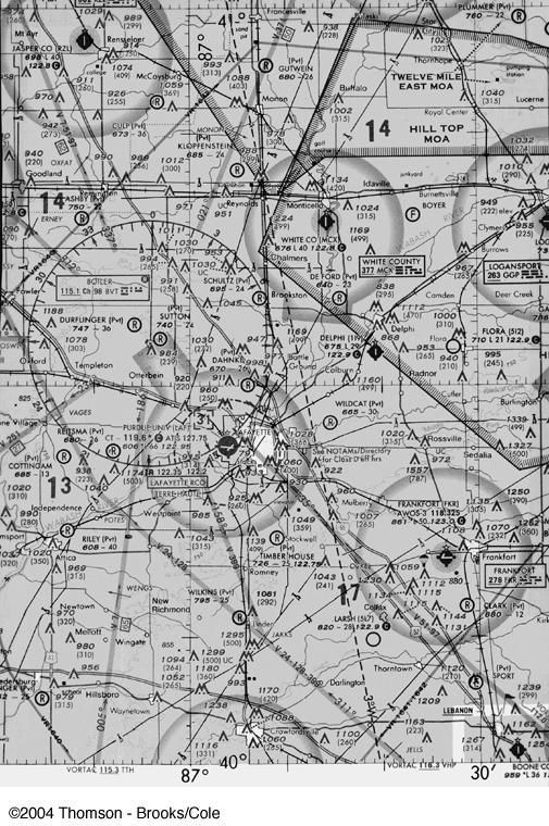
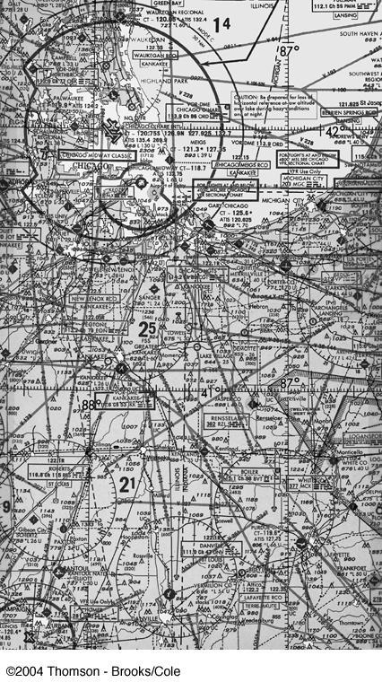
10 Aeronautic Charts Sectional Charts 10
11 11
12 Frankfort Airport Class E Airspace with floor 700 ft above surface Hard-surface runways (2) East-West runway North-South runway, short Frankfort (FKR) Airport AWOS Automated Weather Observation System, Frequency 861 Airport Elevation L - Lighting in Operation Sunrise to Sunset 50 - Longest runway 5000 ft Unicom Frequency, Aeronautical Advisory Station - Common Traffic Advisory Frequency (CTAF) Frankfort Navigation Non-directional Beacon (NDB) 278 Frequency Morse Code for checking Rotating airport beacon in operation sunset to sunrise Miscellaneous Located west of Frankfort City Fuel Services 24 hours Parachute jumping area west of airport Mountains North-east and South-west less than 1000ft Above Ground Level (AGL) Railroad North-South, south of airport East-West, east of airport Page 44, Chap 2, Nolan 12
13 Boiler VORTAC Located at top of small mountain 984 feet above Mean Sea Level 239 feet above Ground Level Name BOILER Frequency Channel 98 ICAO Identifier BVT Morse Code Identification HWAS Page 44, Chap 2, Nolan 13
14 Airway Victor 7 Airway Name Victor 7 65 nm between VORTAC TTH and VORTAC BVT Fly northbound on 5 degree Radial from TTH Fly southbound on 186 Radial from BVT WENGS Intersection using Radials from BVT and <not shown> Page 44, Chap 2, Nolan 14
15 In-class Exercise White County (MCX) Airport using chart on page 42, Chap 2, Nolan Describe VOR from hand-out Describe Airway from hand-out 15
16 16
17 Aircraft Instruments Magnetic Compass Aircraft heading is required to navigate using charts Aeronautic charts drawn to True North Use Magnetic compass Magnetic compass points to Magnetic North (not True North) due to Magnetic Variation of earth Magnetic Variation = True North and Magnetic North In U.S. variation ranges from 0 to 20 degrees Magnetic compass subject to inaccuracies due to: Aircraft accelerations Aircraft turns Stray magnetic fields of aircraft electrical equipment (e.g. windshield heater) 17

18 Aircraft Instruments Magnetic Compass 18
19 Aircraft Instruments Magnetic Compass Magnetic Variation 19

20 Aircraft Instruments Heading Heading indicator uses spinning gyroscope Initialized prior to takeoff using compass rose Subject to drift, must be reset during flight Possible inaccuracies: Initialization errors Internal bearing friction Drift Mechanical failures Indicator 20
 on aircraft Displays (relative) bearing to the NDB Nowdays, located at smaller airports as instrument approach aids 21")
21 Electronic Navigation Non- Directional Beacon NDB transmits radio signal Omni-directional signal Low-medium frequency ( khz) Automatic Direction Finder (ADF) on aircraft Displays (relative) bearing to the NDB Nowdays, located at smaller airports as instrument approach aids 21

22 Electronic Navigation - VOR VOR ground station transmits navigation courses (radials) around the compass Each VOR assigned a radio frequency to mhz Adjacent VORs have different frequencies VOR ground-station 22
23 VOR - Operation VOR transmits two signals: Reference signal (constant in all directions) Variable-phase signal (phase varies with azimuth) VOR Course is determined by difference in phase between Reference and Variable-phase signals At Magnetic North, Variablephase is in phase with Reference signal At Magnetic South, Variablephase is 180 out of phase with Reference signal 23
24 VOR Service Volumes High-altitude VORs Frequency to mhz 200 nautical mile range, between 18,000 and 60,000 feet Low-altitude VORs Frequency to nautical mile range, below 18,000 feet Terminal VORs 2.5 nautical mile range 24
 Known as (lateral) deviation indicator")
25 Using VOR in Cockpit Dial in VOR frequency Dial in desired VOR course using Omni-bearing Selector (OBS) Device shows TO or FROM flag Device shows if aircraft to the left or right of desired course (OBS course) Known as (lateral) deviation indicator 25
26 ATC: From present position, DIRECT TO BRAVO VOR 1. Tune the VOR 2. Identify the VOR (Morse Code) 3. Rotate OBS until leftright needle is centered AND To-From Indicator is TO 4. Number is Course to VOR (inbound) Inbound Course (195 ) is reciprocal of Radial 5. Turn and fly heading, keep needle centered 15 TO BRAVO BRA
27 ATC: From present position intercept and fly outbound on 320 radial from BRAVO VOR 1. Tune and identify station 2. Select 320 on OBS Outbound: Course = Radial 3. To-From Indicator is FROM 320 FROM BRAVO BRA
28 ATC: Cleared direct BRAVO 20 knot cross wind 1. Tune and identify VOR and steer heading If heading 350 is maintained, aircraft will drift to left of 350 radial 3. Turn and fly heading 360 until needle centered Repeat bracketing maneuver until find heading to compensate for crosswind BRAVO BRA TO 350 TO TO 350 WIND 28
29 Flying V42 airway. ATC: Report crossing CRIB Intersection 027 TO 316 CRIB Notes: When tuning side radial, needle points to VOR before reaching radial (needle points away from VOR after passing radial) CLEVELAND CLE Ch TO 316 AKRON (OHIO) ACO Ch
30 Theta-Theta Position Computation Pilot obtain bearing from two VORs Plot lines from each VOR Intersection is location of aircraft Best VOR geometry is 90 VOR receiver accurate to +/- 6 Smallest intersection area is when VORs at right angles 270 Radial VOR A 180 Radial VOR A VOR B VOR B 225 Radial 180 Radial 30
31 Distance Measuring Equipment (DME) DME provides aircraft distance to ground-station Slant-range distance Interrogator on aircraft transmits pulsed interrogation signal Transponder on ground responds to interogator signal Elapsed Range Time is computed Range Time for signal to travel 1 nm is microseconds Slant Range = (Interrogator Time Reception of Transponder Time)/ micro-sconds 31
32 Rho-Theta Position Computation Position is based on Bearing from VOR and Distance from DME VOR and DME colocated at know location 225 Radial 40nm VOR/DME 32
33 Airways Airways defined by radials between VORs Airways dimensions 4nm on either side of center-line Spread-out due to VOR radials Changeover Point (COP) Fix between two navigational aids where pilot ceases to track radial FROM VOR and starts to track radial TO VOR Airways designated with identifying numbers Preceded by V (Victor), if low altitude Preceded by J (Jet), if high altitude 33
34 MEAs and MOCAs Minimum En-route Altitude (MEA) Designated for each airway Aircraft operating above MEA guaranteed clear on obstruction, terrain Guaranteed proper VOR reception (200nm or 40nm) Minimum Obstruction Clearance Altitudes (MOCAs) Designated for some airways Less than MEAs Used in case of emergency require lower altitude Guaranteed proper VOR reception only if within 22nm of VOR 34
35 Global Navigation Satellite System (GNSS) GNSS (GPS in US) Min 21 operational satellites in orbit + 3 spares GPS computes: Position (latitude/longitude) Altitude Velocity (ground speed) Time 35
36 GPS Operation Position computation based on ranging and triangulation GPS receiver on aircraft measures distance from satellite to aircraft using (fixed) travel time of a radio signal Satellite transmits Course/Acquisition (C/A) code with info on satellite position (=ephemeris) GPS compares actual time with Satellite transmitted time and uses difference to compute distance (= pseudo-range) GPS requires distance from 3 satellites (+ time from fourth) 36
37 GPS Accuracy Receiver Autonomous Integrity Monitor (RAIM) Independent means to determine if satellite is providing corrupted information Requires data from 5 th satellite 37
38 WAAS Wide Area Augmentation System (WAAS) Differential GPS signal 35 ground-reference stations Accurately surveyed location Receive signals from satellites Determine errors Corrections broadcast from geo-stationary satellite above US Used for all enroute navigation Also Category I approaches 38
39 LAAS Local Area Augmentation System (LAAS) Complement WAAS for Cat II, Cat III approaches Transmits correction information from airport to 30nm radius 39
40 Inertial Navigation System Equipment on aircraft Computes position (3-D) and velocities Computations based on accelerometers and angular rate gyros Initialized with lat/lon prior to flight in stationary position Accelerations measured and integrated to yield velocities, integrated to yield position Very expensive units accurate to +/-2.5nm for 14 hour flight Used for en-route navigation in conjunction with radios and GPS 40
41 Inertial Navigation Systems Measures accelerations in 3-D space Integrate accelerations to get velocities Integrate velocities to get position INS records movement relative to Celestial Sphere (not Earth) Mount INS and turn on. Hour later, INS has not moved, accelerometers have detected earths rotation Drift Any errors in accelerations amplified in velocities and position Compensating for errors, leads to designs for < 0.8nm/hr Schuler Drift 84 minute periodic error (period of pendulum length of diameter of Earth) Over long time, error nulls itself 41
42 Homework 1. Describe the difference between dead-reckoning and pilotage 2. Using VFR Chart VFR Terminal Area Chart: Baltimore- Washington Describe Airport SHANNON Describe VOR BROOKE Describe Airway V Describe the operation of GNSS to determine aircraft position 4. What are the basic principle(s) of operation of WAAS and LAAS 5. What are the limitations of GNSS Prepare for quiz (fill in the blank, multiple choice) next class 42
Chapter 10 Navigation
 Chapter 10 Navigation Table of Contents VHF Omnidirectional Range (VOR) VOR Orientation Course Determination VOR Airways VOR Receiver Check Points Automatic Direction Finder (ADF) Global Positioning System
Page K1. The Big Picture. Pilotage
 Page K1 Pilotage 1. [K1/3/2] Pilotage is navigation by A. reference to flight instruments. B. reference to landmarks. C. reference to airborne satellites. Electronic Elucidation The Big Picture 3. [K4/2/1]
NAVIGATION INSTRUMENTS - BASICS
 NAVIGATION INSTRUMENTS - BASICS 1. Introduction Several radio-navigation instruments equip the different airplanes available in our flight simulators software. The type of instrument that can be found
Navigation Equipment. Pilotage and Dead Reckoning. Navigational Aids. Radio Waves
 1 Navigation Equipment Successful air navigation not only involves piloting an aircraft from place to place, but also not getting lost, not breaking any FAA regulations, and not endangering the safety
NAVIGATION INTRUMENTATION ADF
 1. Introduction NAVIGATION INTRUMENTATION ADF The Automatic Direction Finding (ADF) equipment on-board of aircraft is used together with the Non Directional Beacon (NDB) transmitters installed on the ground.
Exam questions: AE3-295-II
 Exam questions: AE3-295-II 1. NAVIGATION SYSTEMS (30 points) In this question we consider the DME radio beacon. [a] What does the acronym DME stand for? (3 points) DME stand for Distance Measuring Equipment
NAVIGATION (2) RADIO NAVIGATION
 RADIO NAVIGATION") 1 An aircraft is "homing" to a radio beacon whilst maintaining a relative bearing of zero. If the magnetic heading decreases, the aircraft is experiencing: A left drift B right drift C a wind from the
1 An aircraft is "homing" to a radio beacon whilst maintaining a relative bearing of zero. If the magnetic heading decreases, the aircraft is experiencing: A left drift B right drift C a wind from the
not authorized for IFR use. authorized for IFR use under VMC. authorized for IFR use under IMC until the runway is in sight.
 Gleim FAA Test Prep: Instrument Pilot (20 questions) Name: Date: Circle the correct answer on the question sheets AND fill in the corresponding circle on the separate answer sheet. [1] Gleim #: 3.4.32
NDB Approach Background
 NDB Approaches 1 NDB Approach Background One of the oldest and most disliked approaches Can use NDBs both on and off of the destination airport NDB approaches can be on the TO or FROM side of an NDB; some
APPENDIX C VISUAL AND NAVIGATIONAL AIDS
 VISUAL AND NAVIGATIONAL AIDS APPENDIX C VISUAL AND NAVIGATIONAL AIDS An integral part of the airport system is the visual and navigational aids provided to assist pilots in navigating both on the airfield
VOR = VHF Omni-directional Radio Range. Cockpit instrument. Navigation charts Different types. What comes to mind?
 VOR = VHF Omni-directional Radio Range What comes to mind? Cockpit instrument Navigation charts Different types 15-12-2009 VOR 1 VOR training BE V.2.1226 p1 FMC, does not come to mind, although it could
How to Intercept a Radial Outbound
 How to Intercept a Radial Outbound by Greg Whiley Another practical publication from Aussie Star Flight Simulation How to intercepting a radial outbound 1 Greg Whiley Aussie Star Flight Simulation How
2 VHF DIRECTION FINDING
 2 VHF DIRECTION FINDING This chapter explains the principle of operation and the use of the VHF Ground Direction Finding (VDF). VDF provides means of determining the aircraft bearing from a ground station.
AE4-393: Avionics Exam Solutions
 AE4-393: Avionics Exam Solutions 2008-01-30 1. AVIONICS GENERAL a) WAAS: Wide Area Augmentation System: an air navigation aid developed by the Federal Aviation Administration to augment the Global Positioning
Introduction to: Radio Navigational Aids
 Introduction to: Radio Navigational Aids 1 Lecture Topics Basic Principles Radio Directional Finding (RDF) Radio Beacons Distance Measuring Equipment (DME) Instrument Landing System (ILS) Microwave Landing
Cockpit GPS Quick Start Guide
 Cockpit GPS Quick Start Guide Introduction My online book, Cockpit GPS, has grown to over 250 pages. I have that much information because at one time or another I thought that each piece would be useful
Navigation Systems. Chapter 7. Introduction. Ground Wave. Basic Radio Principles
 Chapter 7 Navigation Systems Introduction This chapter provides the basic radio principles applicable to navigation equipment, as well as an operational knowledge of how to use these systems in instrument
The Training Database is supplied as part of the RNS, and is loaded at the same time as the main program.
 THE TRAINING DATABASE The Training Database is supplied as part of the RNS, and is loaded at the same time as the main program. The Training Area is fictious, but the procedures are representative of the
AREA NAVIGATION SYSTEMS
 AREA NAVIGATION SYSTEMS 1. Introduction RNAV is defined as a method of navigation which permits aircraft operation on any desired flight path within the coverage of station-referenced navigation aids or
Understanding VOR's, VORTAC's and How To Use Them
 Understanding VOR's, VORTAC's and How To Use Them by Hal Stoen Used by California Airlines (CAX) with permission from Hal Stoen 1998 first release: 2 December, 1998 INTRODUCTION The practical aspects of
AIRCRAFT AVIONIC SYSTEMS
 AIRCRAFT AVIONIC SYSTEMS B-777 cockpit Package C:\Documents and ettings\administrato Course Outline Radio wave propagation Aircraft Navigation Systems - Very High Omni-range (VOR) system - Instrument Landing
Learning Objectives 062 Radio Navigation
 Learning Objectives 062 Radio Navigation Syllabus 060 00 00 00 NAVIGATION 062 00 00 00 RADIO NAVIGATION 062 01 00 00 BASIC RADIO PROPAGATION THEORY 062 01 01 00 Basic principles 062 01 01 01 Electromagnetic
FOUND FBA-2C1/2C2 BUSH HAWK EQUIPPED WITH SINGLE GARMIN GNS-430 # 1 VHF-AM COMM / VOR-ILS / GPS RECEIVER
 FOUND SUPPLEMENT M400-S11 Transport Canada Approved Flight Manual Supplement For FOUND BUSH HAWK EQUIPPED WITH SINGLE # 1 VHF-AM COMM / VOR-ILS / GPS RECEIVER Section 1 General is Unapproved and provided
INTERCEPT NDB TRACK. This documentation will present an example of NDB track interception performed with a Beechcraft BE90.
 1. Introduction INTERCEPT NDB TRACK This documentation will present an example of NDB track interception performed with a Beechcraft BE90. 2. Initial situation The initial situation is: 1. The aircraft
This page is intentionally blank. GARMIN G1000 SYNTHETIC VISION AND PATHWAYS OPTION Rev 1 Page 2 of 27
 This page is intentionally blank. 190-00492-15 Rev 1 Page 2 of 27 Revision Number Page Number(s) LOG OF REVISIONS Description FAA Approved Date of Approval 1 All Initial Release See Page 1 See Page 1 190-00492-15
P/N 135A FAA Approved: 7/26/2005 Section 9 Initial Release Page 1 of 10
 FAA APPROVED AIRPLANE FLIGHT MANUAL SUPPLEMENT FOR GARMIN GNS 430 - VHF COMM/NAV/GPS Serial No: Registration No: When installing the Garmin GNS 430 - VHF COMM/NAV/GPS in the Liberty Aerospace XL2, this
Avionics Navigation Systems, Second Edition Myron Kayton and Walter R. Fried John Wiley & Sons, Inc (Navtech order #1014)
") Avionics Navigation Systems, Second Edition Myron Kayton and Walter R. Fried John Wiley & Sons, Inc. 1997 (Navtech order #1014) Table of Contents Preface... xvii Acknowledgments... xxi List of Contributors...1
Avionics Navigation Systems, Second Edition Myron Kayton and Walter R. Fried John Wiley & Sons, Inc. 1997 (Navtech order #1014) Table of Contents Preface... xvii Acknowledgments... xxi List of Contributors...1
Communication and Navigation Systems for Aviation
 Higher National Unit Specification General information for centres Unit title: Communication and Navigation Systems for Aviation Unit code: F0M3 35 Unit purpose: This Unit is designed to allow candidates
Apollo GPS Database Addendum
 Apollo GPS Database Addendum This document includes information that has been added to the waypoint database after the printing of the user s guide. A new waypoint type has been added to your database
GA and NextGen How technologies like WAAS and ADS-B will change your flying! Presented By Claire Kultgen
 GA and NextGen How technologies like WAAS and ADS-B will change your flying! Presented By Claire Kultgen Overview 1. TIS 2. ADS-B FIS-B TIS-B ADS-R 3. WAAS 4. T-Routes and GPS MEAs Questions Chat Pilot
A-CR-CCP-803/PF-001 CHAPTER 14 PO 337 DEMONSTRATE AIR NAVIGATION SKILLS
 CHAPTER 14 PO 337 DEMONSTRATE AIR NAVIGATION SKILLS ROYAL CANADIAN AIR CADETS PROFICIENCY LEVEL THREE INSTRUCTIONAL GUIDE SECTION 1 EO M337.01 MEASURE DISTANCE ALONG A ROUTE Total Time: 30 min PREPARATION
Chapter. Spaceship Earth (EAA)
") Chapter 9 Spaceship Earth (EAA) Navigation is the science of getting ships, aircraft or spacecraft from place to place... the method of determining position, course and distance traveled. This is what
Chapter 9 Spaceship Earth (EAA) Navigation is the science of getting ships, aircraft or spacecraft from place to place... the method of determining position, course and distance traveled. This is what
CHANGE 1 CHAPTER FOUR - TACAN AND VOR NAVIGATION...
 CHANGE 1 CHAPTER FOUR - TACAN AND VOR NAVIGATION... 4-1 400. INTRODUCTION... 4-1 401. LESSON TOPIC LEARNING OBJECTIVES... 4-1 402. VOR - TACAN PROCEDURES AND OPERATING INSTRUCTIONS... 4-2 403. HOLDING...
DOD/DFOISR CLEARANCE EXPORT NOTICE. Important Notice. Revision Highlights
 DOD/DFOISR CLEARANCE Cleared for Public Domain Release by the Office of Security Review, dated July 13, 2010, reference number 10-S-2457. EXPORT NOTICE This technical data has been released into the public
2000 by UPS Aviation Technologies, Inc. All rights reserved. Printed in the U.S.A.
 No part of this document may be reproduced in any form or by any means without the express written consent of UPS Aviation Technologies, Inc. UPS Aviation Technologies, Inc., II Morrow, and Apollo are
The Alaska Air Carriers Association. Supports and Advocates for the Commercial Aviation Community
 The Alaska Air Carriers Association Supports and Advocates for the Commercial Aviation Community The Alaska Air Carriers Association membership includes Part 121, 135, 125 and commercial Part 91 air operators.
AERONAUTICAL CHARTS. ordering is available at the National Aeronautical Charting Office (NACO) Web site:
 Web site:") This chapter provides an introduction to crosscountry flying under visual flight rules (VFR). It contains practical information for planning and executing cross-country flights for the beginning pilot.
This chapter provides an introduction to crosscountry flying under visual flight rules (VFR). It contains practical information for planning and executing cross-country flights for the beginning pilot.
Circle the correct answer on the question sheets and fill in the corresponding circle on the separate answer sheet.
 Gleim FAA Test Prep: Instrument Pilot (20 questions) IPGS Study Unit 3: Navigation Systems (IFH Ch 7, PHAK Ch 15) Name: Date: Circle the correct answer on the question sheets and fill in the corresponding
Integrated Cockpit Display System ICDS 1000 Pilot Operation Handbook
 Integrated Cockpit Display System ICDS 1000 Pilot Operation Handbook ICDS1000 Pilot Operating Handbook Revision 1.3 572-0540 page 1 Table Of Contents Electronic Attitude Direction Indicator (EADI)... 8
Airfield Obstruction and Navigational Aid Surveys
 Section I. Section II. Section III. Section IV. Section V. Chapter 7 Airfield Obstruction and Navigational Aid Surveys The purpose of this chapter is to acquaint the Army surveyor with the terminologies
MOONEY AIRCRAFT CORPORATION P. 0. Box 72 Kerrville, Texas FAA APPROVED
 P. 0. Box 72 Kerrville, Texas 78029 FAA APPROVED AIRPLANE FLIGHT MANUAL SUPPLEMENT FOR MOONEY M20J, M20K, M20L, M20M, M20R with Aircraft Serial No. Aircraft Reg. No. This supplement must be attached to
Keywords. DECCA, OMEGA, VOR, INS, Integrated systems
 Keywords. DECCA, OMEGA, VOR, INS, Integrated systems 7.4 DECCA Decca is also a position-fixing hyperbolic navigation system which uses continuous waves and phase measurements to determine hyperbolic lines-of
Aircraft Communication and Navigation Systems
 Unit 86: Aircraft Communication and Navigation Systems Unit code: J/601/7217 QCF level: 4 Credit value: 15 Aim The aim of this unit is to develop learners understanding of the principles of operating aircraft
Basic GPS Operation. by Greg Whiley. Another practical publication from Aussie Star Flight Simulation
 Basic GPS Operation by Greg Whiley Another practical publication from Aussie Star Flight Simulation INTENTIONALLY LEFT BLANK Aussie Star Flight Simulation 2 Basic GPS Operations Statement of copyright
ENSTROM 480/480B OPERATOR S MANUAL AND FAA APPROVED ROTORCRAFT FLIGHT MANUAL SUPPLEMENT GARMIN GNS 430W/530W NAVIGATION SYSTEM
 ENSTROM 480/480B OPERATOR S MANUAL AND FAA APPROVED ROTORCRAFT FLIGHT MANUAL SUPPLEMENT GARMIN GNS 430W/530W NAVIGATION SYSTEM * * * * * REPORT NO. 28-AC-055 HELICOPTER SERIAL NO. HELICOPTER REGISTRATION
PERFORM A DME ARC. This document illustrates how to perform a DME arc with a HSI-equipped Beechcraft 90. Descent steps
 PERFORM A DME ARC 1. Introduction This document illustrates how to perform a DME arc with a HSI-equipped Beechcraft 90. 2. Preparatory work 2.1. Scenario You will need to open the following charts of Clermont
Fokker 50 - Automatic Flight Control System
 GENERAL The Automatic Flight Control System (AFCS) controls the aircraft around the pitch, roll, and yaw axes. The system consists of: Two Flight Directors (FD). Autopilot (AP). Flight Augmentation System
Automatic Dependent Surveillance -ADS-B
 ASECNA Workshop on ADS-B (Dakar, Senegal, 22 to 23 July 2014) Automatic Dependent Surveillance -ADS-B Presented by FX SALAMBANGA Regional Officer, CNS WACAF OUTLINE I Definition II Principles III Architecture
Instrument Flight Procedures - Glass Cockpits
 Instrument Flight Procedures - Glass Cockpits The concepts contained here are general in nature and can be used by all however, they are targeted toward glass cockpits and, more specifically, integrated
RADIO NAVIGATION
 details and associated Learning Objectives ATPL CPL ATPL/ ATPL CPL 062 00 00 00 RADIO NAVIGATION 062 01 00 00 BASIC RADIO PROPAGATION THEORY 062 01 01 00 Basic principles 062 01 01 01 Electromagnetic waves
Avilon TM. vor ils gps waas. nextgen
 NextGen NextGen We are in the midst of the most significant advancement in aviation technology in more than sixty years. NextGen (Next Generation Air Transportation System), the FAA s airspace modernization
Aerobasics An Introduction to Aeronautics
 Aerobasics An Introduction to Aeronautics 14. Air Navigation Principles S P Govinda Raju S P Govinda Raju retired as professor from the Department of Aerospace Engineering, Indian Institute of Science
INSTALLATION MANUAL AND OPERATING INSTRUCTIONS
 INSTALLATION MANUAL AND OPERATING INSTRUCTIONS MD200-202/203/206/207 Series COURSE DEVIATION INDICATOR Mid-Continent Instruments and Avionics Manual Number 8017702 9400 E. 34 th Street N. Wichita, KS 67226
TITLE PAGE CAGE CODE CONTRACT NO. IR&D OTHER. PREPARED ON PC/Word for Windows 7.0 FILED UNDER
 TITLE PAGE CAGE CODE 8205 THIS DOCUMENT IS: CONTROLLED BY B-E ALL REVISIONS TO THIS DOCUMENT SHALL BE APPROVED BY THE ABOVE ORGANIZATION PRIOR TO RELEASE. PREPARED UNDER - - x CONTRACT NO. IR&D OTHER PREPARED
AN/APN-242 Color Weather & Navigation Radar
 AN/APN-242 Color Weather & Navigation Radar Form, Fit and Function Replacement for the APN-59 Radar Previous Configuration: APN-59 Antenna Stabilization Data Generator Antenna Subsystem Radar Receiver
Cockpit Visualization of Curved Approaches based on GBAS
 www.dlr.de Chart 1 Cockpit Visualization of Curved Approaches based on GBAS R. Geister, T. Dautermann, V. Mollwitz, C. Hanses, H. Becker German Aerospace Center e.v., Institute of Flight Guidance www.dlr.de
VOR/DME APPROACH WITH A320
 1. Introduction VOR/DME APPROACH WITH A320 This documentation presents an example of a VOR/DME approach performed with an Airbus 320 at LFRS runway 21. This type of approach is a non-precision approach
MGL Avionics. Odyssey/Voyager G2 and iefis
 MGL Avionics Odyssey/Voyager G2 and iefis Navigation This document applies to G2 version 1.1.0.1 or later, iefis 1.0.0.3 or later. Note: This document is based on the G2. The iefis system provides identical
Mode 4A Unsafe terrain clearance with landing gear not down and flaps not in landing position
 1.6.18 Ground Proximity Warning System Allied Signal Aerospace (Honeywell) manufactures the GPWS, part number 965-0648- 008. The GPWS provides the following alerts if thresholds are exceeded: Mode 1 Excessive
INSTALLATION MANUAL AND OPERATING INSTRUCTIONS
 INSTALLATION MANUAL AND OPERATING INSTRUCTIONS MD200-302/303/306/307 Series COURSE DEVIATION INDICATOR MID-CONTINENT INST. CO., INC MANUAL NUMBER 8017972 Revisions Rev. Date Description of Change ECO#
INSTALLATION MANUAL AND OPERATING INSTRUCTIONS
 INSTALLATION MANUAL AND OPERATING INSTRUCTIONS MD222-( ) SERIES TWO-INCH COURSE DEVIATION INDICATOR Mid-Continent Instruments and Avionics Manual Number 9016311 9400 E. 34 th Street N. Wichita, KS 67226
Series III Avionics Pilot's Guide
 Chelton Avionics Inc. A Chelton Group Company 6400 Wilkinson Drive Prescott, AZ 86305 U.S.A. 150-041074 Rev. B i Wulfsberg Electronics Division, located in Prescott, Arizona, designs and manufactures the
Copyrighted Material - Taylor & Francis
 22 Traffic Alert and Collision Avoidance System II (TCAS II) Steve Henely Rockwell Collins 22. Introduction...22-22.2 Components...22-2 22.3 Surveillance...22-3 22. Protected Airspace...22-3 22. Collision
Introduction. Traffic Symbology. System Description SECTION 12 ADDITIONAL FEATURES
 12.2 Traffic Advisory Systems (TAS) Introduction All information in this section pertains to the display and control of the Garmin GNS 430/GTS 800 interface. NOTE: This section assumes the user has experience
Table of Contents. Introduction 3. Pictorials of the 40 and 50 Systems 4. List of Applicable Acronyms 6
 Table of Contents Introduction 3 Pictorials of the 40 and 50 Systems 4 List of Applicable Acronyms 6 System 40 Modes of Operation 7 System 40 Functional Preflight Procedures 10 System 40 In Flight Procedures
Impact of ATC transponder transmission to onboard GPS-L5 signal environment
 SCRSP-WG IP-A10 18 May 2006 SURVEILLANCE AND CONFLICT RESOLUTION SYSTEMS PANEL (SCRSP) TENTH MEETING WG-A Montreal, May, 2006 WG-A Agenda Item 9 Any Other Bussiness Impact of ATC transponder transmission
Pilot s Guide KCS 55A. Bendix/King Compass System
 Pilot s Guide KCS 55A Bendix/King Compass System Introduction to the King KCS 55A Compass System... 3 Panel display: KI 525A Pictorial Navigation Indicator... 4 KA 516 Slaving Control and Compensator...
Aviation Benefits of GNSS Augmentation
 Aviation Benefits of GNSS Augmentation Workshop on the Applications of GNSS Chisinau, Moldova 17-21 May 2010 Jeffrey Auerbach Advisor on GNSS Affairs Office of Space and Advanced Technology U.S. Department
Regulations. Aeronautical Radio Service
 Regulations Aeronautical Radio Service Version 1.0 Issue Date: 30 December 2009 Copyright 2009 Telecommunications Regulatory Authority (TRA). All rights reserved. P O Box 26662, Abu Dhabi, United Arab
A Review of Vulnerabilities of ADS-B
 A Review of Vulnerabilities of ADS-B S. Sudha Rani 1, R. Hemalatha 2 Post Graduate Student, Dept. of ECE, Osmania University, 1 Asst. Professor, Dept. of ECE, Osmania University 2 Email: ssrani.me.ou@gmail.com
Satellite Navigation (and positioning)
") Satellite Navigation (and positioning) Picture: ESA AE4E08 Instructors: Sandra Verhagen, Hans van der Marel, Christian Tiberius Course 2010 2011, lecture 1 Today s topics Course organisation Course contents
Satellite Navigation (and positioning) Picture: ESA AE4E08 Instructors: Sandra Verhagen, Hans van der Marel, Christian Tiberius Course 2010 2011, lecture 1 Today s topics Course organisation Course contents
GLOBAL POSITIONING SYSTEMS. Knowing where and when
 GLOBAL POSITIONING SYSTEMS Knowing where and when Overview Continuous position fixes Worldwide coverage Latitude/Longitude/Height Centimeter accuracy Accurate time Feasibility studies begun in 1960 s.
EE Chapter 14 Communication and Navigation Systems
 EE 2145230 Chapter 14 Communication and Navigation Systems Two way radio communication with air traffic controllers and tower operators is necessary. Aviation electronics or avionics: Avionic systems cover
ADF-650D Automatic Direction Finder System Pilot s Operating Handbook
 ADF-650D Automatic Direction Finder System Pilot s Operating Handbook V O L 1.1 2 0 MHz ADF List of Effective Pages * Asterisk indicates pages changed, added, or deleted by revision. Record of Revisions
Cooperation Agreements for SAR Service and COSPAS-SARSAT
 SAR/NAM/CAR/SAM IP/15 International Civil Aviation Organization 07/05/09 Search and Rescue (SAR) Meeting for the North American, Caribbean and South American Regions (SAR/NAM/CAR/SAM) (Puntarenas, Costa
SAFETYSENSE LEAFLET 25 USE OF GPS
 SAFETYSENSE LEAFLET 25 USE OF GPS Most illustrations courtesy of Garmin UK and Honeywell 1. INTRODUCTION 2. SYSTEM AND SIGNAL ANOMALIES 3. EQUIPMENT 4. SYSTEM FAMILIARISATION 5. FLIGHT PLANNING 6. PROGRAMMING
GBAS FOR ATCO. June 2017
 GBAS FOR ATCO June 2017 Disclaimer This presentation is for information purposes only. It should not be relied on as the sole source of information, and should always be used in the context of other authoritative
An Introduction to Airline Communication Types
 AN INTEL COMPANY An Introduction to Airline Communication Types By Chip Downing, Senior Director, Aerospace & Defense WHEN IT MATTERS, IT RUNS ON WIND RIVER EXECUTIVE SUMMARY Today s global airliners use
F-104 Electronic Systems
 Information regarding the Lockheed F-104 Starfighter F-104 Electronic Systems An article published in the Zipper Magazine # 49 March-2002 Author: Country: Website: Email: Theo N.M.M. Stoelinga The Netherlands
Range Sensing strategies
 Range Sensing strategies Active range sensors Ultrasound Laser range sensor Slides adopted from Siegwart and Nourbakhsh 4.1.6 Range Sensors (time of flight) (1) Large range distance measurement -> called
Anywhere Map Quadra OWNERS MANUAL. Control Vision Corp. Pittsburg Kansas Sales Support
 Anywhere Map Quadra OWNERS MANUAL Elements of this product are protected under US patent numbers 6,804,585 and 7,167,782. Other patents may be pending Control Vision Corp. Pittsburg Kansas www.anywheremap.com
Experiences in. Flight Inspecting GBAS
 Experiences in Flight Inspecting GBAS Thorsten Heinke Aerodata AG 1 Flight Inspection of GBAS Overview Basics Requirements Equipment Flight Inspection 2 Ground Based Augmentation System VDB Tx-Frequency
Use of Satellite-based Technologies to Enhance safety and efficiency in ATC and Airport Operation
 Use of Satellite-based Technologies to Enhance safety and efficiency in ATC and Airport Operation Presented by Felix Tsao Senior Electronics Engineer Civil Aviation Department 26 May 2017 1 Briefing on
NMEA2000- Par PGN. Mandatory Request, Command, or Acknowledge Group Function Receive/Transmit PGN's
 PGN Number Category Notes - Datum Local geodetic datum and datum offsets from a reference datum. T The Request / Command / Acknowledge Group type of 126208 - NMEA - Request function is defined by first
Briefing the Approach
 Transcript Briefing the Approach Featuring: Doug Stewart Copyright PilotWorkshops.com, LLC. This material is available to members of the PilotWorkshops.com web site, which is the only place it can be legally
DLR Project ADVISE-PRO Advanced Visual System for Situation Awareness Enhancement Prototype Introduction The Project ADVISE-PRO
 DLR Project ADVISE-PRO Advanced Visual System for Situation Awareness Enhancement Prototype Dr. Bernd Korn DLR, Institute of Flight Guidance Lilienthalplatz 7 38108 Braunschweig Bernd.Korn@dlr.de phone
10 Secondary Surveillance Radar
 10 Secondary Surveillance Radar As we have just noted, the primary radar element of the ATC Surveillance Radar System provides detection of suitable targets with good accuracy in bearing and range measurement
Integrated navigation systems
 Chapter 13 Integrated navigation systems 13.1 Introduction For many vehicles requiring a navigation capability, there are two basic but conflicting requirements to be considered by the designer, namely
Japan-US Aviation Environmental Workshop Fukutake Hall University of Tokyo 29 November 2017
 Japan-US Aviation Environmental Workshop Fukutake Hall University of Tokyo 29 November 2017 Keiichi Tamura All Nippon Airways B787 Technical Pilot, Dr. Eng. 2 Fundamentals of PBN (RNAV / RNP) Fundamentals
PBN fleet equipage according to FPL content. Michel ROELANDT
 PBN fleet equipage according to FPL content Michel ROELANDT EUROCONTROL RAiSG/PBN TF Meeting March 2014 Introduction 15 Nov 2012: standard ICAO format for airline flight plans changed. New fields have
2 Flight Plans 1 Fill in the appropriate boxes 2 Find acceptable routes 3 Useful Newbie Comments
 VATSIM Requirement 1 Download and install essential software 1 Your Sim MSFS, XPlane 2 Pilot Clients SB, FSInn 3 To find ATC Wazzaup, Servinfo, VATSpy, VATSIM Stats, Pilot Client 4 Interpreting This Requirement
GPS 101. An Introduction to Using a GPS Receiver
 GPS 101 An Introduction to Using a GPS Receiver The goal of this presentation if to provide a basic understanding of what is GPS, how it works, provide some basic terminology and to provide ideas on how
Alternate Position, Navigation & Time APNT for Civil Aviation
 Alternate Position, Navigation & Time APNT for Civil Aviation For Working Group B of the International GNSS Committee Shanghai, May 2011 by Per Enge & Leo Eldredge Work supported by the Federal Aviation
2000 by UPS Aviation Technologies, Inc. All rights reserved. Printed in the U.S.A.
 No part of this document may be reproduced in any form or by any means without the express written consent of UPS Aviation Technologies, Inc. UPS Aviation Technologies, Inc., II Morrow, and Apollo are
MINIMUM EQUIPMENT LIST OPERATIONAL PROCEDURES ATA 34 NAVIGATION F100 ATA 34/ NAVIGATION CAA-01 ATA 34
 1 of 12 ATA 34/ NAVIGATION 2 of 12 11-1 Static ports Dispatch with ports at one side inoperative Take-off: With the static ports capped at one side, compensation for slip and crosswind conditions (take-off
The prior specification for navaid data was XP NAV810, which was compatible with X-Plane Changes in the spec for XP NAV1100 were:
 X-PLANE NAVIGATION DATA FOR NAVAIDS (USER_NAV.DAT & EARTH_NAV.DAT) FILE SPECIFICATION VERSION 1100 REVISION HISTORY 7 May 2009 Spec converted to this new format to support new web site (http://data.x-plane.com).
AIRLINE TRANSPORT PILOTS LICENSE ( NAVIGATION)
") 062 00 00 00 RADIO NAVIGATION 062 01 00 00 RADIO AIDS 062 01 01 00 Ground Direction Finder D/F (including classification of bearings) Principles Describe the role of a Ground Direction Finder Explain why
062 00 00 00 RADIO NAVIGATION 062 01 00 00 RADIO AIDS 062 01 01 00 Ground Direction Finder D/F (including classification of bearings) Principles Describe the role of a Ground Direction Finder Explain why
CIVIL AVIATION REQUIREMENTS SECTION 4 - AERODROME STANDARDS & AIR TRAFFIC SERVICES SERIES 'D', PART II 12 TH JULY 2006 EFFECTIVE: FORTHWITH
 GOVERNMENT OF INDIA OFFICE OF DIRECTOR GENERAL OF CIVIL AVIATION TECHNICAL CENTRE, OPP SAFDARJANG AIRPORT, NEW DELHI CIVIL AVIATION REQUIREMENTS SECTION 4 AERODROME STANDARDS & AIR TRAFFIC SERVICES SERIES
Modern ARINC 743B DO-229D and DO-253C GLSSU Solutions For Retrofit
 Commercial Aviation Modern ARINC 743B DO-229D and DO-253C GLSSU Solutions For Retrofit Presented to AEEC March 2010 The Classic Retrofit Challenge Financial: Operating budget year financing ROI payback:
Radar and Navigational Aids. Navigational Aids By K M Vyas DIET Rajkot
 Radar and Navigational Aids Navigational Aids By K. M. Vyas DIET, Rajkot 1 Introduction Navigation : The art of directing the movements of a craft (object) from one point to another along a desired path