Probing for oscilloscope
|
|
|
- Amberly Holland
- 6 years ago
- Views:
Transcription


1 Probing for oscilloscope
2 Agenda - Notion de sonde en oscilloscopie - Structure des différentes sondes - Passives - Actives - Logiques - Différentielles - Comment choisir la bonne sonde - Nouvelle technologie pour sonde différentielle
3 Sonde, notions Voltage Logic Current Optical Passive Active Passive Active Passive Active Z0 High Z Differential High Voltage Single- Differential Ended AC DC AC


4 Sonde, Intégrité et fidélité Original signal Signal at probe tip is changed Signal at the oscilloscope Signal display with DSP correction
5 Sonde Idéale R in = C in = 0 CABLE BANDWIDTH = The ideal probe would have no effect on the signal being measured, zero loading. Infinite Bandwidth Zero Input Capacitance Infinite Input Resistance Attenuation of 1 Zero Delay Zero Phase Shift Mechanically well suited to application Infinite Dynamic Range
6 Sonde Réelle C C V CC R C Without probe Gain = - R C R E f 0 = 1 2 R C C C V IN PROBE R P C P With probe Gain = - (R C R P ) f 0 = R E 1 2 (R C R P )(C C +C P ) R E NOTE: V CC is an AC Ground
7 Sonde Réelle Impédance R in acts like a voltage divider Higher input resistance less loading Lower source resistance less loading DUT Probe R source Probe Tip R In E source L Ground Lead C In Decreased Signal Amplitude V meas = V source R in R in + R source 100% 90% 100% 90% 10% 0% 10% 0% Source Signal Effects of Input Resistance

8 Sonde Réelle Charge

9 Sonde Réelle Inductance

10 Sonde Réelle Inductance Masse
11 Amplitude Sonde Réelle BW/Rise Time 3% 10% Frequency 20% 30% The signal delivered to the oscilloscope Insufficient BW degrades the front edge Follow the 1/5 th Rule T system < T r,signal T r,measured = (T r,signal ) 2 + (T r, system ) 2 5 Actual Measured
12 1X Probe Model (Length of Cable) DUT PROBE SCOPE R source V source Probe Tip L Ground Lead PROBE CABLE 8-10 pf/ft * 1.5 ns/ft 6 feet 1 MΩ 20 pf Advantages: 1X (No Attenuation) Inexpensive Disadvantages: Very High Reflections Very High Input C Very Low Bandwidth * Typical 50 Ω cable has about 30 pf/ft of capacitance
13 Typical High Z 10X Passive Probe Model DUT C pf PROBE SCOPE R source V source Advantages: Probe Tip 9 MΩ R1 High Input R Wide Dynamic Range Inexpensive Mechanically Rugged Low Input C vs 1X Probe L Ground Lead PROBE CABLE 8-10 pf/ft 1.5 ns/ft 6 feet 500 Ω C pf Disadvantages: Input C Too High R3 Not Compatible with 50 Ω Systems Must be Compensated 1 MΩ R2 C2 20 pf
14 50 Ω Divider Probe (Z0) Model (10X) DUT 450 Ω PROBE SCOPE R source V source 0.5 pf Probe Tip L Ground Lead PROBE CABLE 50 Ω 50 Ω 6 feet Advantages: Low Input C Wide Bandwidth to 9 GHz Compatible with 50 Ω Systems and 1 MΩ with Termination Resistor No Compensation Necessary Disadvantages: Low Input R Must be Terminated into 50 Ω
15 Active Probe Model DUT PROBE 6 feet SCOPE R source V source Probe Tip L Ground Lead BUFFER AMP PROBE CABLE 50 Ω R t 50 Ω 1 M Ω / 50 Ω Advantages: Low Input Capacitance Wide Bandwidth High Input R Compatible with 50Ω Systems or 1 MΩ with Termination Resistor R t No Compensation Necessary Disadvantages: Higher Cost Limited Dynamic Range Mechanically Less Rugged Requires Power
16 Active Differential Probes PROBE SCOPE + _ V OUT CH1 Scope Amplifier Typical CMRR 10,000 : DC 2000 : 20 MHz Advantages: Lower Input Capacitance Higher CMRR vs Frequency Than Passive Differential Pair Compatible With 50 and 1 M Single-ended Systems Disadvantages: Higher Cost Limited Dynamic Range Mechanically Less Rugged and Larger Size Requires Power


17 TPP1000 TPP0500 TPP0502 Passive Probes


18 Sondes Trimode 30GHz
 + (V-)/2 with respect to ground Serial Data standards such as PCI Express, Serial ATA, etc require both differential and maximum")
19 TriMode Probing TriMode, with a single probe-dut connection, allows: Traditional differential measurements: V+ to V- Independent single ended measurements on either input V+ with respect to ground V- with respect to ground Direct common mode measurements: (V+) + (V-)/2 with respect to ground Serial Data standards such as PCI Express, Serial ATA, etc require both differential and maximum permissible common mode voltage limit measurements. Requires two separate probes --- Until Now! 19
20 Sonde, le bon choix

21 Probing Impedance loading

22 Input Impedance P73xx Input C ~ 0.21pF TriMode P75xx Avec charge modification forme du signal Input Impedance (Ohms) A P7516 P Input C ~ 0.05pF` Pas de charge Pas de modification forme du signal Impédance Flat E+04 10K 1.00E K 1.00E+06 1M 1.00E+07 10M 1.00E M 1.00E+09 1G 1.00E+10 10G 1.00E G Frequency (Hz) 9/19/2016 TEKTRONIX CONFIDENTIAL 22
23 ISOVu, nouvelle technologie

24 What Limits Power Measurements? THE PROBE S INABILITY TO DELIVER AN ACCURATE SIGNAL No probe today has the combination of bandwidth, common mode voltage and common mode rejection Today s probes derate over bandwidth Voltage, loading and CMRR Long leads make the probe susceptible to noise and radiated emissions The waveform shape changes based on the lead dress and the position of the probe head Large hook clips are inadequate for dense environments and lack performance Susceptible to ground loops 19 SEPTEMBER

25 Voltage Derates Over Bandwidth YOU DON T GET THE FULL DYNAMIC RANGE AT FULL BANDWIDTH The specified dynamic range is only true for DC and low frequencies This 100 MHz 1 kv RMS probe starts to roll off at 2 MHz 2 MHz 19 SEPTEMBER

26 Understanding the Measurement Issue THE EFFECT OF COMMON MODE VOLTAGE A V A-B V Out V Diff B V CM 40 V A V Diff ~0V 1V V Diff : 0 V 1 V V CM : 40 V B 40 V 19 SEPTEMBER

27 CMRR Derates Over Bandwidth POWER MEASUREMENTS REQUIRE A PROBE WITH HIGH CMRR 19 SEPTEMBER
.")
28 Designing Blind THE EFFECT OF COMMON MODE VOLTAGE Gate Driver Vdiff mvs to ± 50V Conventional differential probing systems don t have the required combination of bandwidth and common mode rejection Vcm < 2000V Engineers are forced to rely on simulation, workarounds, or inferences (forced to measure to ground). 19 SEPTEMBER

29 What is IsoVu Technology? ISOLATED MEASUREMENT SYSTEM IsoVu technology is a radically new measurement system platform Enables high-resolution measurements on differential signals Utilizes an electro-optic sensor to convert the input signal to optical modulation Galvanically isolates the device-under-test Incorporates: 4 separate lasers Optical sensor Power over fiber 5 optical fibers Sophisticated feedback and control techniques 19 SEPTEMBER

30 IsoVu Doesn t Derate Over Bandwidth YOU GET THE FULL DYNAMIC RANGE AT FULL BANDWIDTH IsoVu is the only product in the world with a flat derating 19 SEPTEMBER

31 IsoVu Offers 1 Million to 1 CMRR ISOVU IS 100,000 TIMES BETTER THAN STANDARD SOLUTION 1 Million to 1 at 100 MHz More than 10,000 to 1 at 1 GHz 19 SEPTEMBER
 3.")
32 High-Side Gate Measurements OPTIMIZATION AND TUNING MAY BE IMPOSSIBLE Three characteristic regions during turn on: 1. C GS : Charge Time 2. Miller Plateau: Time required to charge the gate-drain Miller capacitance (C GD ) 3. Conduction: Gate charges to its final value 19 SEPTEMBER

33 Making Signal Details Visible 1 GHZ BANDWIDTH, 2000 V CM AND 1,000,000:1 CMRR LeCroy DA1855A IsoVu Gate Driver Vdiff mvs to ± 50V IsoVu rejects common mode noise, so you can see small differential signals in the presence of common mode voltages Vcm < 2000V Engineers can confirm simulations and evaluate signal characteristics, such as this ringing. 19 SEPTEMBER

34 Technologie Optique Mach-Zehnder 19 SEPTEMBER
 3 meter and 10 meter options TekVPI Interface Controller Optical Fiber Sensor Head Probe Tip 19 SEPTEMBER 2016 35")
35 IsoVu Overview ISOLATED HIGH VOLTAGE MEASUREMENT SYSTEM Scope 50Ω Term Fiber optic isolation Power over Fiber (no batteries required) 3 meter and 10 meter options TekVPI Interface Controller Optical Fiber Sensor Head Probe Tip 19 SEPTEMBER
36 Merci
IsoVu Optically Isolated DC - 1 GHz Measurement System Offers >120 db CMRR with 2kV Common Mode Range
 IsoVu Optically Isolated DC - 1 GHz Measurement System Offers >120 db CMRR with 2kV Common Mode Range Introduction This white paper describes the optically isolated measurement system architecture trademarked
Practical Measurements considerations for GaN and SiC technologies ANDREA VINCI EMEA MARKET DEVELOPMENT MANAGER POWER ELECTRONICS
 Practical Measurements considerations for GaN and SiC technologies ANDREA VINCI EMEA MARKET DEVELOPMENT MANAGER POWER ELECTRONICS PLEASED TO MEET YOU 2 Evolving Test Solutions with Semiconductors WAFER
 1 of 6 03/12/2012 14:56 2012-12-03 HAMEG > Products > Accessories > Probes http://www.hameg.com/186.0.html P R O B E S H Z 5 6-2 * AC/ DC Current Clamps This AC/DC Current Probe is used to measure currents
Isolation Addresses Common Sources of Differential Measurement Error
 By Tom Neville A typical measurement system includes an oscilloscope and an oscilloscope probe that provides the connection between the device under test (DUT) and the oscilloscope. Probe selection is
Probe Considerations for Low Voltage Measurements such as Ripple
 Probe Considerations for Low Voltage Measurements such as Ripple Our thanks to Tektronix for allowing us to reprint the following article. Figure 1. 2X Probe (CH1) and 10X Probe (CH2) Lowest System Vertical
Measurement and Analysis for Switchmode Power Design
 Measurement and Analysis for Switchmode Power Design Switched Mode Power Supply Measurements AC Input Power measurements Safe operating area Harmonics and compliance Efficiency Switching Transistor Losses
Probing challenges when testing WBG devices power-conference.com/
 Probing challenges when testing WBG devices power-conference.com/ Andrea Vinci Business Development EMEA Automotive &Power Solutions Tektronix: supporting humankind's greatest advances and future vision
Measuring Vgs on Wide Bandgap Semiconductors APPLICATION NOTE
 Measuring Vgs on Wide Bandgap Semiconductors This application note focuses on accurate high-side V GS measurements using the IsoVu measurement system. The measurements described in this application note
ELC224 Final Review (12/10/2009) Name:
 Name:") ELC224 Final Review (12/10/2009) Name: Select the correct answer to the problems 1 through 20. 1. A common-emitter amplifier that uses direct coupling is an example of a dc amplifier. 2. The frequency
ELC224 Final Review (12/10/2009) Name: Select the correct answer to the problems 1 through 20. 1. A common-emitter amplifier that uses direct coupling is an example of a dc amplifier. 2. The frequency
Differential Amplifier : input. resistance. Differential amplifiers are widely used in engineering instrumentation
 Differential Amplifier : input resistance Differential amplifiers are widely used in engineering instrumentation Differential Amplifier : input resistance v 2 v 1 ir 1 ir 1 2iR 1 R in v 2 i v 1 2R 1 Differential
TAKE THE MYSTERY OUT OF PROBING. 7 Common Oscilloscope Probing Pitfalls to Avoid
 TAKE THE MYSTERY OUT OF PROBING 7 Common Oscilloscope Probing Pitfalls to Avoid Introduction Understanding common probing pitfalls and how to avoid them is crucial in making better measurements. In an
Probes and Accessories
 99 Washington Street Melrose, MA 02176 Phone 781-665-1400 Toll Free 1-800-517-8431 Visit us at www.testequipmentdepot.com Probes and Accessories Your Guide to Selecting the Right Probe Measurement Accuracy
PML 711A-RO High impedance passive probe Features:
 High impedance passive probe Features: 2.5 mm Diameter Tip CeramCore TM Hybrid Probe Coaxial Design Interchangeable Spring Contact Tip IC Contacting System 0.5 to 1.27 mm pitch PMK introduces a new universal
9 Specifications. Specifications NOMINAL CHARACTERISTICS
 9 Specifications Specifications NOMINAL CHARACTERISTICS WARRANTED CHARACTERISTICS Nominal characteristics describe parameters and attributes that are guaranteed by design, but do not have associated tolerances.
Low Power. Video Op Amp with Disable AD810 REV. A. Closed-Loop Gain and Phase vs. Frequency, G = +2, R L = 150, R F = 715 Ω
 CLOSED-LOOP db SHIFT Degrees DIFFERENTIAL % DIFFERENTIAL Degrees a FEATURES High Speed MHz Bandwidth ( db, G = +) MHz Bandwidth ( db, G = +) V/ s Slew Rate ns Settling Time to.% ( = V Step) Ideal for Video
As all PMK probes the PML 751-RO features CeramCore TM technology. The entire probe
 High impedance passive probe Features: 2.5 mm Diameter Tip Useable with any 50 Ω Instrument Interchangeable Spring Contact Tip IC Contacting System 0.5 to 1.27 mm pitch PMK introduces a new universal 10:1
PML 791-RO. High impedance passive probe. Features: 2.5 mm Diameter Tip. Coaxial Design. Interchangeable Spring Contact Tip
 High impedance passive probe Features: 2.5 mm Diameter Tip Coaxial Design Interchangeable Spring Contact Tip IC Contacting System 0.5 to 1.27 mm pitch PMK introduces a new universal 100:1 miniature probe
Introduction to Analog Interfacing. ECE/CS 5780/6780: Embedded System Design. Various Op Amps. Ideal Op Amps
 Introduction to Analog Interfacing ECE/CS 5780/6780: Embedded System Design Scott R. Little Lecture 19: Operational Amplifiers Most embedded systems include components that measure and/or control real-world
High Voltage Differential Probes HVD3605A, HVD3206A HVD310xA
 High Voltage Differential Probes HVD3605A, HVD3206A HVD310xA Key Features 1 kv, 2 kv, 6 kv CAT safety rated models Widest differential voltage ranges available Exceptional common-mode rejection ratio (CMRR)
350MHz, Ultra-Low-Noise Op Amps
 9-442; Rev ; /95 EVALUATION KIT AVAILABLE 35MHz, Ultra-Low-Noise Op Amps General Description The / op amps combine high-speed performance with ultra-low-noise performance. The is compensated for closed-loop
PDN Probes. P2100A/P2101A Data Sheet. 1-Port and 2-Port 50 ohm Passive Probes
 P2100A/P2101A Data Sheet PDN Probes 1-Port and 2-Port 50 ohm Passive Probes power integrity PDN impedance testing ripple PCB resonances transient step load stability and NISM noise TDT/TDR clock jitter
Measurement Techniques
 Measurement Techniques Primary measurement tool: Oscilloscope Other lab tools: Logic Analyser, Gain-Phase Analyser, Spectrum Analyser Visualisation of electrical signals in the time domain Visualisation
CX1100 Series Current and Differential Sensors
 DATA SHEET CX00 Series Current and Differential Sensors CX0A Current Sensor, Single Channel CX0A Current Sensor, Dual Channel CX03A Current Sensor, Low Side CX04A Current Sensor, Selectable Resistive Sensor
AN-1106 Custom Instrumentation Amplifier Design Author: Craig Cary Date: January 16, 2017
 AN-1106 Custom Instrumentation Author: Craig Cary Date: January 16, 2017 Abstract This application note describes some of the fine points of designing an instrumentation amplifier with op-amps. We will
Description, operating instructions and hardware specification of the HL Transverse balance measurement module (TBMM).
.") , operating instructions and hardware specification of the HL 8240 - Transverse balance measurement module (TBMM). The increasing use of telecom equipment in ultrafast applications has enhanced the need
, operating instructions and hardware specification of the HL 8240 - Transverse balance measurement module (TBMM). The increasing use of telecom equipment in ultrafast applications has enhanced the need
EMC of Power Converters
 Alain CHAROY - (0033) 4 76 49 76 76 - a.charoy@aemc.fr EMC EMC of Power Converters Friday 9 May 2014 Electromagnetism is just electricity Converters are particularly concerned with EMC: Conducted disturbances
PHV RO. High impedance passive probe. Features: CeramCore TM Hybrid Probe. Modular Construction. Coaxial Design
 High impedance passive probe Features: CeramCore TM Hybrid Probe Modular Construction Coaxial Design Interchangeable Spring Contact Tip Certificate of Calibration available on request Read-out BNC Connector
Keysight Measuring High Impedance Sources Using the U8903B Audio Analyzer. Application Note
 Keysight Measuring High Impedance Sources Using the U8903B Audio Analyzer Application Note Introduction This note details the input impedance of the U8903B Audio Analyzer, and shows that this needs to
Supplied in carry case with additional accessories The PHV 1000-RO is a 400 MHz, standard sized, 100:1 passive probe designed for instruments
 High impedance passive probe Features: CeramCore TM hybrid probe Modular construction Coaxial design Interchangeable spring contact tip Certificate of calibration available on request Read-out BNC connector
Homework Assignment 03
 Homework Assignment 03 Question 1 (Short Takes), 2 points each unless otherwise noted. 1. Two 0.68 μf capacitors are connected in series across a 10 khz sine wave signal source. The total capacitive reactance
A 19-GHz Broadband Amplifier Using a g m -Boosted Cascode in 0.18-μm CMOS
 A 19-GHz Broadband Amplifier Using a g m -Boosted Cascode in 0.18-μm CMOS Masum Hossain & Anthony Chan Carusone Electrical & Computer Engineering University of Toronto Outline Applications g m -Boosting
Applied Electronics II
 Applied Electronics II Chapter 3: Operational Amplifier Part 1- Op Amp Basics School of Electrical and Computer Engineering Addis Ababa Institute of Technology Addis Ababa University Daniel D./Getachew
FlexRay Communications System. Physical Layer Common mode Choke EMC Evaluation Specification. Version 2.1
 FlexRay Communications System Physical Layer Common mode Choke EMC Evaluation Specification Version 2.1 Disclaimer DISCLAIMER This specification as released by the FlexRay Consortium is intended for the
Memo. 1 Summary. 1.1 Introduction. 1.2 Experiments. 1.3 Conclusion
 Topic: Tested: Date: Author: High frequency oscillations measured with high bandwidth current sensors at low current Pearson 2878 and SDN-414 shunts with different resistance values 2014 April 11 th Martin
Switched Mode Power Supply Measurements
 Power Analysis 1 Switched Mode Power Supply Measurements AC Input Power measurements Safe operating area Harmonics and compliance Efficiency Switching Transistor Losses Measurement challenges Transformer
FEATURES TYPICAL APPLICATIO. LT1194 Video Difference Amplifier DESCRIPTIO APPLICATIO S
 FEATURES Differential or Single-Ended Gain Block: ± (db) db Bandwidth: MHz Slew Rate: /µs Low Cost Output Current: ±ma Settling Time: ns to.% CMRR at MHz: db Differential Gain Error:.% Differential Phase
AC Current Probes CT1 CT2 CT6 Data Sheet
 View at www.testequipmentdepot.com AC Current Probes CT1 CT2 CT6 Data Sheet Features & Benefits High Bandwidth Ultra-low Inductance Very Small Form Factor Characterize Current Waveforms up to
Keysight Technologies N2792A/N2818A 200 MHz and N2793A/N2819A 800 MHz Differential Probes. Data Sheet
 Keysight Technologies N2792A/N2818A 200 MHz and N2793A/N2819A 800 MHz Differential Probes Data Sheet Introduction The Keysight Technologies, Inc. N2792A/93A and N2818A/19A differential probes provide the
ULTRA HIGH SPEED SINGLE OPERATIONAL AMPLIFIER
 ULTRA HIGH SPEED SINGLE OPERATIONAL AMPLIFIER GENERAL DESCRIPTION The NJM711 is an ultra high speed single operational amplifier. It can swings 6V/µs high slew rate and 1GHz gain band width product(1mhz
Differential Amplifiers
 Differential Amplifiers Benefits of Differential Signal Processing The Benefits Become Apparent when Trying to get the Most Speed and/or Resolution out of a Design Avoid Grounding/Return Noise Problems
Passive Probe Ground Lead Effects
 Passive Probe Ground Lead Effects TECHNICAL BRIEF June 20, 2013 Summary All passive probes have some bandwidth specification which is generally in the range of a few hundred megahertz up to one gigahertz.
Low noise Amplifier, simulated and measured.
 Low noise Amplifier, simulated and measured. Introduction: As a study project a low noise amplifier shaper for capacitive detectors in AMS 0.6 µm technology is designed and realised. The goal was to design
1-Input/4-Output Video Distribution Amplifiers MAX4137/MAX4138
 -00; Rev 0; / EVALUATION KIT AVAILABLE General Description The / are -input/-output voltagefeedback amplifiers that combine high speed with fast switching for video distribution applications. The is internally
Instrumentation amplifier
 Instrumentationamplifieris a closed-loop gainblock that has a differential input and an output that is single-ended with respect to a reference terminal. Application: are intended to be used whenever acquisition
ABCs of Probes. Primer
 ABCs of Probes Primer Primer Tektronix Probe Selector With this on-line, interactive tool you can select by series, model number, or standards/application and fine tune your search with your specific testing
EXAM Amplifiers and Instrumentation (EE1C31)
") DELFT UNIVERSITY OF TECHNOLOGY Faculty of Electrical Engineering, Mathematics and Computer Science EXAM Amplifiers and Instrumentation (EE1C31) April 18, 2017, 9.00-12.00 hr This exam consists of four
DELFT UNIVERSITY OF TECHNOLOGY Faculty of Electrical Engineering, Mathematics and Computer Science EXAM Amplifiers and Instrumentation (EE1C31) April 18, 2017, 9.00-12.00 hr This exam consists of four
Guide Version Five techniques for fast, accurate power integrity measurements
 Guide Version 01.00 Five techniques for fast, accurate power integrity measurements Rail voltages are getting smaller, and tolerances are decreasing. As a result, making accurate power rail measurements
Infiniium Series Oscilloscope Probes, Accessories, and Options
 99 Washington Street Melrose, MA 02176 Phone 781-665-1400 Toll Free 1-800-517-8431 Visit us at www.testequipmentdepot.com Back to the Agilent 1153A Product Info Page Infiniium Series Oscilloscope Probes,
PART MAX4144ESD MAX4146ESD. Typical Application Circuit. R t IN- IN+ TWISTED-PAIR-TO-COAX CABLE CONVERTER
 9-47; Rev ; 9/9 EVALUATION KIT AVAILABLE General Description The / differential line receivers offer unparalleled high-speed performance. Utilizing a threeop-amp instrumentation amplifier architecture,
PowerAmp Design. PowerAmp Design PAD112 HIGH VOLTAGE OPERATIONAL AMPLIFIER
 PowerAmp Design Rev C KEY FEATURES LOW COST HIGH VOLTAGE 150 VOLTS HIGH OUTPUT CURRENT 5 AMPS 50 WATT DISSIPATION CAPABILITY 100 WATT OUTPUT CAPABILITY INTEGRATED HEAT SINK AND FAN COMPATIBLE WITH PAD123
POSSIBLE SUBSTITUTE PRODUCT HA-2842, HA-2544
 OBSOLETE PRODUCT POSSIBLE SUBSTITUTE PRODUCT HA2842, HA2544 5MHz, Fast Settling, Unity Gain Stable, Video Operational Amplifier DATASHEET FN2843 Rev 4. The HA2841 is a wideband, unity gain stable, operational
Micropower, Single-Supply, Rail-to-Rail, Precision Instrumentation Amplifiers MAX4194 MAX4197
 General Description The is a variable-gain precision instrumentation amplifier that combines Rail-to-Rail single-supply operation, outstanding precision specifications, and a high gain bandwidth. This
200 ma Output Current High-Speed Amplifier AD8010
 a FEATURES 2 ma of Output Current 9 Load SFDR 54 dbc @ MHz Differential Gain Error.4%, f = 4.43 MHz Differential Phase Error.6, f = 4.43 MHz Maintains Video Specifications Driving Eight Parallel 75 Loads.2%
Improved Second Source to the EL2020 ADEL2020
 Improved Second Source to the EL ADEL FEATURES Ideal for Video Applications.% Differential Gain. Differential Phase. db Bandwidth to 5 MHz (G = +) High Speed 9 MHz Bandwidth ( db) 5 V/ s Slew Rate ns Settling
LVDS Flow Through Evaluation Boards. LVDS47/48EVK Revision 1.0
 LVDS Flow Through Evaluation Boards LVDS47/48EVK Revision 1.0 January 2000 6.0.0 LVDS Flow Through Evaluation Boards 6.1.0 The Flow Through LVDS Evaluation Board The Flow Through LVDS Evaluation Board
High Voltage Differential Probes HVD3605, HVD3206 HVD310x
 High Voltage Differential Probes HVD3605, HVD3206 HVD310x Key Features 1 kv, 2 kv, 6 kv CAT safety rated models World s only 1500 Vdc safety rated probe per IEC/EN 61010-031:2015 Widest differential voltage
Passive High Voltage Probes P5100A-TPP0850-P5122-P5150-P6015A Datasheet
 Passive High Voltage Probes P5100A-TPP0850-P5122-P5150-P6015A Datasheet P5150 DC to 500 MHz 2500 V Peak, 1000 V RMS CAT II 50 X Floatable up to 600 V RMS CAT II or 300 V RMS CAT III For TPS2000 and THS3000
School of Sciences. ELECTRONICS II ECE212A 2 nd Assignment
 School of Sciences SPRING SEMESTER 2010 INSTRUCTOR: Dr Konstantinos Katzis COURSE / SECTION: ECE212N COURSE TITLE: Electronics II OFFICE RM#: 124 (1 st floor) OFFICE TEL#: 22713296 OFFICE HOURS: Monday
TT-SI MHz Active Differential Probe
 INSTRUCTION MANUAL TT-SI 9110 100MHz Active Differential Probe These probe is in compliance with EN61010-031:2002+A1:2008 CAT III, Pollution Degree 2 1. Safety Terms and Symbols Terms appear in this manual:
High Current, High Power OPERATIONAL AMPLIFIER
 High Current, High Power OPERATIONAL AMPLIFIER FEATURES HIGH OUTPUT CURRENT: A WIDE POWER SUPPLY VOLTAGE: ±V to ±5V USER-SET CURRENT LIMIT SLEW RATE: V/µs FET INPUT: I B = pa max CLASS A/B OUTPUT STAGE
PowerAmp Design. PowerAmp Design PAD117A RAIL TO RAIL OPERATIONAL AMPLIFIER
 PowerAmp Design RAIL TO RAIL OPERATIONAL AMPLIFIER Rev J KEY FEATURES LOW COST RAIL TO RAIL INPUT & OUTPUT SINGLE SUPPLY OPERATION HIGH VOLTAGE 100 VOLTS HIGH OUTPUT CURRENT 15A 250 WATT OUTPUT CAPABILITY
Traceability for Oscilloscopes and Oscilloscope Calibrators
 Traceability for Oscilloscopes and Oscilloscope Calibrators in relation to RF Voltage measurements Paul C. A. Roberts Fluke Precision Measurement PCAR Traceability for Scope Cal Mar 2006 1 Introduction
AN-671 APPLICATION NOTE One Technology Way P.O. Box 9106 Norwood, MA Tel: 781/ Fax: 781/
 APPLICATION NOTE One Technology Way P.O. Box 910 Norwood, MA 0202-910 Tel: 781/329-4700 Fax: 781/32-8703 www.analog.com Reducing RFI Rectification Errors in In-Amp Circuits By Charles Kitchin, Lew Counts,
ISSCC 2003 / SESSION 10 / HIGH SPEED BUILDING BLOCKS / PAPER 10.8
 ISSCC 2003 / SESSION 10 / HIGH SPEED BUILDING BLOCKS / PAPER 10.8 10.8 10Gb/s Limiting Amplifier and Laser/Modulator Driver in 0.18µm CMOS Technology Sherif Galal, Behzad Razavi Electrical Engineering
Nonlinear Macromodeling of Amplifiers and Applications to Filter Design.
 ECEN 622(ESS) Nonlinear Macromodeling of Amplifiers and Applications to Filter Design. By Edgar Sanchez-Sinencio Thanks to Heng Zhang for part of the material OP AMP MACROMODELS Systems containing a significant
DUAL ULTRA MICROPOWER RAIL-TO-RAIL CMOS OPERATIONAL AMPLIFIER
 ADVANCED LINEAR DEVICES, INC. ALD276A/ALD276B ALD276 DUAL ULTRA MICROPOWER RAILTORAIL CMOS OPERATIONAL AMPLIFIER GENERAL DESCRIPTION The ALD276 is a dual monolithic CMOS micropower high slewrate operational
Choosing the right Pico Technology active differential probe
 Pico Technology offers many active s covering a wide range of voltages, category (CAT) ratings and bandwidths. As the name suggests, these probes have two major features: Active: Active probes achieve
250 MHz, General Purpose Voltage Feedback Op Amps AD8047/AD8048
 5 MHz, General Purpose Voltage Feedback Op Amps AD8/AD88 FEATURES Wide Bandwidth AD8, G = + AD88, G = + Small Signal 5 MHz 6 MHz Large Signal ( V p-p) MHz 6 MHz 5.8 ma Typical Supply Current Low Distortion,
400MHz, Ultra-Low-Distortion Op Amps
 9; Rev ; /97 EVALUATION KIT AVAILABLE MHz, Ultra-Low-Distortion Op Amps General Description The MAX8/MAX9/MAX8/MAX9 op amps combine ultra-high-speed performance with ultra-lowdistortion operation. The
Schlöder GmbH - EMC Test and Measurement Systems Model #
 Schlöder GmbH - EMC Test and Measurement Systems Model # Product Description IEC / EN 61000-4 - 2 ESD SESD 216 ESD generator 10 kv CON / 16,5 kv AIR acc. to IEC 61000-4-2, 150 pf / 330 ohm SESD 230 ESD
Oscilloscope Probes and Accessories
 Oscilloscope Probes and Accessories Pomona s oscilloscope probes give you the full range you need. Designed, rated, and specified to match the bandwidth of your instrument, they provide you with full voltage
MIC915. Features. General Description. Applications. Ordering Information. Pin Configuration. Pin Description. Dual 135MHz Low-Power Op Amp
 MIC915 Dual 135MHz Low-Power Op Amp General Description The MIC915 is a high-speed, unity-gain stable operational amplifier. It provides a gain-bandwidth product of 135MHz with a very low, 2.4mA supply
Multi-function Gain-Phase Analyzer (Frequency Response Analyzer) Model 2505
 Model 2505") OTHER PRODUCTS.. Multi-function Gain-Phase Analyzer ( Response Analyzer) Model 2505 Standard Configurations Gain phase analyzer response analyzer Phase Angle Voltmeter (PAV) Fast dual channel wide-band
OTHER PRODUCTS.. Multi-function Gain-Phase Analyzer ( Response Analyzer) Model 2505 Standard Configurations Gain phase analyzer response analyzer Phase Angle Voltmeter (PAV) Fast dual channel wide-band
N2820A/21A High-Sensitivity, High Dynamic Range Current Probes
 N2820A/21A High-Sensitivity, High Dynamic Range Current Probes Data Sheet See the details without losing sight of the big picture Key features and specifications Measure currents as low as 50 µa Measure
Op-Amp Simulation Part II
 Op-Amp Simulation Part II EE/CS 5720/6720 This assignment continues the simulation and characterization of a simple operational amplifier. Turn in a copy of this assignment with answers in the appropriate
Low Capacitance Probes Minimize Impact on Circuit Operation
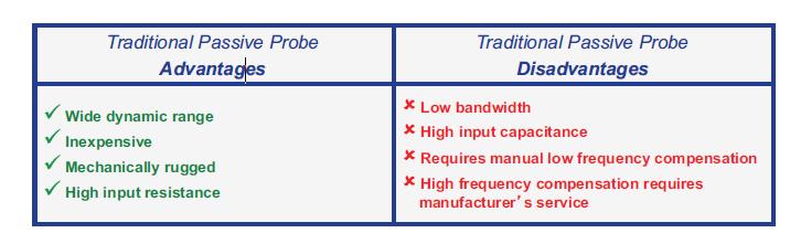
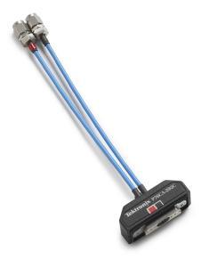
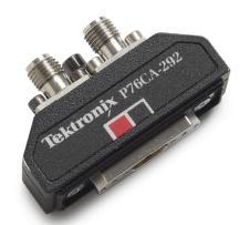
 Presented by TestEquity - www.testequity.com Low Capacitance Probes Minimize Impact on Circuit Operation Application Note Application Note Traditional Passive Probe Advantages Wide dynamic range Inexpensive
B. Equipment. Advanced Lab
 Advanced Lab Measuring Periodic Signals Using a Digital Oscilloscope A. Introduction and Background We will use a digital oscilloscope to characterize several different periodic voltage signals. We will
ECE2019 Sensors, Signals, and Systems A Lab #6: Electromagnetic Field Sensing
 ECE2019 Sensors, Signals, and Systems A 2012 Lab #6: Electromagnetic Field Sensing Introduction This lab involves construction of circuits which demonstrate electromagnetic properties of cables used in
Effectively Using the EM 6992 Near Field Probe Kit to Troubleshoot EMI Issues
 Effectively Using the EM 6992 Near Field Probe Kit to Troubleshoot EMI Issues Introduction The EM 6992 Probe Kit includes three magnetic (H) field and two electric (E) field passive, near field probes
CONNECTING THE PROBE TO THE TEST INSTRUMENT
 2SHUDWLRQ 2SHUDWLRQ Caution The input circuits in the AP034 Active Differential Probe incorporate components that protect the probe from damage resulting from electrostatic discharge (ESD). Keep in mind
N2790A 100 MHz, N2791A 25 MHz and N2891A 70 MHz High-voltage Differential Probes
 N2790A 100 MHz, N2791A 25 MHz and N2891A 70 MHz High-voltage Differential Probes Data Sheet Oscilloscope users often need to make floating measurements where neither point of the measurement is at earth
New Technique Accurately Measures Low-Frequency Distortion To <-130 dbc Levels by Xavier Ramus, Applications Engineer, Texas Instruments Incorporated
 New Technique Accurately Measures Low-Frequency Distortion To
Single Supply, Low Power Triple Video Amplifier AD813
 a FEATURES Low Cost Three Video Amplifiers in One Package Optimized for Driving Cables in Video Systems Excellent Video Specifications (R L = 15 ) Gain Flatness.1 db to 5 MHz.3% Differential Gain Error.6
Active: Active probes achieve low input capacitance and high sensitivity by buffering and amplifying the signal close to the point of measurement.
 Application Note Pico Technology offers many s covering a wide range of voltages, category (CAT) ratings and bandwidths. As the name suggests, these probes have two major features: Active: Active probes
WaveLink High Bandwidth Differential Probing System (16 GHz 25 GHz)
") WaveLink High Bandwidth Differential Probing System (16 GHz 25 GHz) 25 GHz Solder-In Lead Ultra-compact Browser Superior Probe Impedance Superior Noise Performance EXCEPTIONAL BANDWIDTH AND SIGNAL FIDELITY
WaveLink High Bandwidth Differential Probing System (16 GHz 25 GHz) 25 GHz Solder-In Lead Ultra-compact Browser Superior Probe Impedance Superior Noise Performance EXCEPTIONAL BANDWIDTH AND SIGNAL FIDELITY
Probing Techniques for Signal Performance Measurements in High Data Rate Testing
 Probing Techniques for Signal Performance Measurements in High Data Rate Testing K. Helmreich, A. Lechner Advantest Test Engineering Solutions GmbH Contents: 1 Introduction: High Data Rate Testing 2 Signal
ZS Series High Impedance Active Probes 2.5 GHz, 1.5 GHz and 1 GHz Probes
 ZS Series 2.5 GHz, 1.5 GHz and 1 GHz Probes zs series high impedance active zs series high impedance active probes probes The ZS Series probes provide high impedance and an extensive set of probe tips
Calibration Techniques for the Home Lab
 Calibration Techniques for the Home Lab Jacques Audet VE2AZX jacaudet@videotron.ca Web: ve2azx.net September 2018 ve2azx.net 1 Summary - Using a reference multimeter as a calibrator for less accurate instruments.
P7600 Series TriMode Probes
 P7600 Series TriMode Probes TekConnect Interface - TekConnect scope/probe control and usability Direct control from probe compensation box or from scope menu Applications Including, but not limited to:
LeCroy PowerMeasure System. Get the Complete Picture
 LeCroy PowerMeasure System Get the Complete Picture Power Measurements Made Easy! COMPLETE PACKAGE! POWER DEVICE ANALYSIS: measures power device saturation voltage, instantaneous power loss, safe operating
Experiment 1: Instrument Familiarization (8/28/06)
") Electrical Measurement Issues Experiment 1: Instrument Familiarization (8/28/06) Electrical measurements are only as meaningful as the quality of the measurement techniques and the instrumentation applied
Electrical Measurement Issues Experiment 1: Instrument Familiarization (8/28/06) Electrical measurements are only as meaningful as the quality of the measurement techniques and the instrumentation applied
DC MHZ PXI Differential Instrumentation Amplifier
 DC - 100 MHZ PXI Differential Instrumentation Amplifier Differential 100 V Common Mode Input DC - 100 MHz Bandwidth AC/DC Coupling Programmable Attenuation/Gain/ Offset 9 nv/ Input Noise 50 Ω Output Impedance
10. High-Boost HAM. Design Guide & Applications Manual. Maxi, Mini, Micro Family DC-DC Converters and Configurable Power Supplies
 The High-Boost Harmonic Attenuator Module Compatible with V375, VI-26x and VI-J6x Families The High-Boost Harmonic Attenuation Module (HAM) consists of a full-wave rectifier, a high-frequency zero-current
Matched N-Channel JFET Pairs
 U/ Matched N-Channel JFET Pairs Part Number V GS(off) (V) V (BR)GSS Min (V) Min I G Typ (pa) V GS V GS Max (mv) U to 5.5 U to 5.5 Two-Chip Design High Slew Rate Low Offset/Drift Voltage Low Gate Leakage:
Low Cost, General Purpose High Speed JFET Amplifier AD825
 a FEATURES High Speed 41 MHz, 3 db Bandwidth 125 V/ s Slew Rate 8 ns Settling Time Input Bias Current of 2 pa and Noise Current of 1 fa/ Hz Input Voltage Noise of 12 nv/ Hz Fully Specified Power Supplies:
C H A P T E R 02. Operational Amplifiers
 C H A P T E R 02 Operational Amplifiers The Op-amp Figure 2.1 Circuit symbol for the op amp. Figure 2.2 The op amp shown connected to dc power supplies. The Ideal Op-amp 1. Infinite input impedance 2.
LM4562 Dual High Performance, High Fidelity Audio Operational Amplifier
 Dual High Performance, High Fidelity Audio Operational Amplifier General Description The is part of the ultra-low distortion, low noise, high slew rate operational amplifier series optimized and fully
TETRIS 1000 High Impedance Active Probe. Instruction Manual
 TETRIS 1000 High Impedance Active Probe Instruction Manual Copyright 2015 PMK GmbH All rights reserved. Information in this publication supersedes that in all previously published material. Specifications
N2790A 100 MHz, N2791A 25 MHz and N2891A 70 MHz High-voltage Differential Probes
 N2790A 100 MHz, N2791A 25 MHz and N2891A 70 MHz High-voltage Differential Probes Data Sheet Oscilloscope users often need to make floating measurements where neither point of the measurement is at earth
LINEAR IC APPLICATIONS
 1 B.Tech III Year I Semester (R09) Regular & Supplementary Examinations December/January 2013/14 1 (a) Why is R e in an emitter-coupled differential amplifier replaced by a constant current source? (b)