PRODUCT MANUAL. AGD Systems Limited 2016 Doc. Ref. 932 PM ISS3 ISO ISO 9001 Registered Quality Management. Registered Environmental Management
|
|
|
- Austin Brown
- 6 years ago
- Views:
Transcription


1 ISO PRODUCT MANUAL ISO 9001 Registered Quality Management 015 Registered Environmental Management 015 AGD Systems Limited 2016 Doc. Ref. 932 PM ISS3
2 TABLE OF CONTENTS INTRODUCTION Product & technology 3 Key features 3 Typical applications 4 Product overview 4 DISPLAY / CONFIGURATION Screen mode operation 5 Information display Pulse/Transmit mode 5 Continuous mode 5 Screen modes 6 Start up screen 6 Select radar type 6 Setting the target speed values 7 User selectable speed values 7 Setting the radar mounting angle 8 Setting the radar range 8 Setting speed measurement - kph/mph 9 Setting target type 9 Set to recede or advance 10 Save settings 10 Pulse/Transmit or Continuous mode 10 Low battery warning 11 Shutting the unit down 11 Information display Pulse/Transmit mode 12 Continuous mode 12 Tracked target mode 12 Queue mode 12 Free flow mode 12 Screen modes 13 Start up screen 13 Select radar type 13 Setting the target speed values 14 User selectable speed values 14 Setting the radar mounting angle 15 Setting the radar range 15 Setting speed measurement - kph/mph 16 Setting target type 16 Set to recede or advance 17 Modes of operation (pulse) 17 Modes of operation (continuous) 17 Modes of operation (tracked) 18 Modes of operation (queue) 18 Modes of operation (fast flow) 18 Channel frequency 19 Save settings 19 Low battery warning 19 Shutting the unit down 19 CONFIGURATION Adjustable parameters 20 Pre-set speed values 20 TECHNICAL SPECIFICATIONS Product specification 21 CERTIFICATION IMPORTANT SAFETY INFORMATION Safety precautions 24 DISCLAIMER 28 Warranty 28 2


3 INTRODUCTION PRODUCT & TECHNOLOGY 932 The AGD932 is a compact purpose designed portable radar target simulator that can be used to test radars on site for correct operation and speed reporting. A number of special features have been designed into the target simulator including user selectable pre-set speed values or capability to set specific speed values as required and vehicle type. The target simulator features a number of user adjustable parameters via an intuitive user interface allowing quick and easy set up in a roadside environment. KEY FEATURES Lightweight ergonomic profile State-of-the-art radar technology Ease of set up in road side environment Intuitive user Interface User selectable pre-set speed values User definable specific speed values Battery powered (2x AA) 3


4 INTRODUCTION TYPICAL APPLICATIONS Target simulation PRODUCT OVERVIEW Power on / off press and hold for 1 second to power up or power down unit (auto power off after 5 minutes) Up / Down Scroll through options. Inverse highlighted item identifies the currently selected parameter Information display Select / Accept / Return Select highlighted option / accept change Activate Test Audible confirmation given Battery compartment cover - takes 2x AA batteries Compartment 4
5 DISPLAY / CONFIGURATION SCREEN MODE OPERATION The 932 menu system works on a basic principal whereby the screen will cycle through the menu options as shown below. The return button allows you to enter a menu and the up/down arrows allow you to adjust settings, pressing the return button will cycle you to the next menu option. SELECT RADAR MODEL SELECT SPEED (pre-set values) SELECT ANGLE (if relevant to model) SELECT RANGE (if relevant to model) SET SPEED UNITS SET VEHICLE TYPE SET DIRECTION SAVE SETTINGS SET MODE (Pulse or Continuous)* SELECT CUSTOM SPEED (if required) 5 *The 350 radar has extra modes available, please refer to relevant section in this manual


6 DISPLAY / CONFIGURATION INFORMATION DISPLAY 342 PULSE/TRANSMIT MODE Radar type Target speed preset values or user defined Advance (recede) CONTINUOUS MODE Radar type Cosine (radar mounting angle) Radar range Speed units Vehicle type Save settings } If relevant to radar type SCREEN MODES Start up screen On powering up the 932 will display a splash screen. The current software version is shown on the bottom left, along with the detector model the 932 has been calibrated for. Select radar type The screen will switch to Select Radar automatically, here you can scroll up or down using the arrows to select the radar you wish to test. Press return to select and move to next screen. Please note that the orientation of the unit varies with radar type due to the e field polarisation - horizontal or vertical. 6
7 DISPLAY / CONFIGURATION SETTING THE TARGET SPEED VALUES The large numbers indicating the pre-set speed setting is highlighted ready for input. The default setting is 30Km/Hr, press return to make active, the numbers will flash you can use the up/ down arrows to amend the speed, see the table on page 11 for the pre-set values. The presets will simply cycle through from minimum to maximum range - 20Km/Hr (12mph) to 320Km/Hr (200mph). To select the speed press the return button. The sample screens show the minimum speed setting of 21Km/Hr and the maximum speed setting of 320Km/Hr. NOTE: certain radars may only support certain speed values. USER SELECTABLE SPEED VALUES You can highlight the individual numbers, i.e. hundreds, tens and units to set your own speed measurement. Toggle through each unit then press return to set. 7
8 DISPLAY / CONFIGURATION SETTING THE RADAR MOUNTING ANGLE The next setting displayed is the radar target mounting angle - top right. Minimum angle is 0º - maximum is 30º, use the return button to make active and arrows buttons to alter value, either up or down. Press return again to set. NOTE: certain radars may not require mounting angle adjustment. SETTING THE RADAR RANGE The radar range can be set from a minimum of zero metres to a maximum of 96 metres. The value increments will depend on the radar type. NOTE: This function is only available on certain radar types. 8
9 DISPLAY / CONFIGURATION SETTING MEASUREMENT - KPH/MPH The next setting allows you to toggle between kph and mph. SETTING THE TARGET TYPE There are 3 options for target type, Car, Van and Lorry. Simple cycle through the options and press return to select. 9

10 DISPLAY / CONFIGURATION SET TO RECEDE OR ADVANCE There is a simple toggle button to select either recede or advance. Press return to select. SAVE SETTINGS Arrow forward to the save settings button bottom right and press return. TRANSMIT & CONTINUOUS MODE This option allows you to decide between transmit or continuous mode. 10
11 DISPLAY / CONFIGURATION LOW BATTERY WARNING If during operation the batteries become depleted the unit will warn you with this message before automatically shutting down. Simply replace batteries x2 AA and restart to continue. SHUTTING THE UNIT DOWN Holding the power on button for more than one second will shut the unit down. We would advise removing the batteries if the unit is not going to be used for long period. 11
 If relevant to Radar range } radar type Speed units Vehicle type Save settings Channel frequency TRACKED TARGET MODE Radar type")
 If relevant to Radar range } radar type Speed units Vehicle type Save settings")
12 IMPORTANT DISPLAY / CONFIGURATION 350 RADAR INFORMATION DISPLAY 350 PULSE/TRANSMIT MODE Radar type Target speed preset values or user defined Advance (recede) Channel frequency CONTINUOUS MODE Radar type Cosine (radar mounting angle) If relevant to Radar range } radar type Speed units Vehicle type Save settings Channel frequency TRACKED TARGET MODE Radar type Target speed preset values or user defined 12 Advance (recede) Channel frequency QUEUE MODE Radar type Cosine (radar mounting angle) If relevant to Radar range } radar type Speed units Vehicle type Save settings Channel frequency FREE FLOW MODE Radar type Cosine (radar mounting angle) If relevant to Radar range } radar type Speed units Vehicle type Save settings Channel frequency

13 IMPORTANT DISPLAY / CONFIGURATION 350 RADAR SCREEN MODES Start up screen On powering up the 932 will display a splash screen. The current software version is shown on the bottom left, along with the detector model the 932 has been calibrated for. Select radar type The screen will switch to Select Radar automatically, here you can scroll up or down using the arrows to select the radar you wish to test. Press return to select and move to next screen. Please note that the orientation of the unit varies with radar type due to the e field polarisation - horizontal or vertical. 13
14 IMPORTANT DISPLAY / CONFIGURATION 350 RADAR SETTING THE TARGET SPEED VALUES The large numbers indicating the pre-set speed setting is highlighted ready for input. The default setting is 30Km/Hr, press return to make active, the numbers will flash you can use the up/ down arrows to amend the speed. See the table on page 11 for the pre-set values. The presets will simply cycle through from minimum to maximum range - 21Km/Hr (12mph) to 320Km/Hr (200mph). To select the speed press the return button. The sample screens show the minimum speed setting of 21Km/Hr and the maximum speed setting of 320Km/Hr. NOTE: certain radars may only support certain speed values. USER SELECTABLE SPEED VALUES You can highlight the individual numbers, i.e. hundreds, tens and units to set your own speed measurement. Toggle through each unit then press return to set. 14
15 IMPORTANT DISPLAY / CONFIGURATION 350 RADAR SETTING THE RADAR MOUNTING ANGLE The next setting displayed is the radar target mounting angle - top right. Minimum angle is 0º - maximum is 30º, use the return button to make active and arrows buttons to alter value, either up or down. Press return again to set. NOTE: It is advised to use the radar in a setting of 0º for the 350 radar. Please ensure to also set the mounting angle correctly in the radar. SETTING THE RADAR RANGE The radar range can be set from a minimum of zero metres to a maximum of 85.2 metres. The value increments will depend on the radar type. NOTE: This function is only available on certain radar types. 15
16 IMPORTANT DISPLAY / CONFIGURATION 350 RADAR SETTING MEASUREMENT - KPH/MPH The next setting allows you to toggle between kph and mph. SETTING THE TARGET TYPE There are 3 options for target type, Car, Van and Lorry. Simply cycle through the options and press return to select. 16
 This option allows you to choose between five modes in the 350 radar: Pulse/transmit Mode: This mode is selected by highlighting the mode of operation icon.")
17 IMPORTANT DISPLAY / CONFIGURATION 350 RADAR SET TO RECEDE OR ADVANCE There is a simple toggle button to select either recede or advance. Press return to select. MODES OF OPERATION (PULSE) This option allows you to choose between five modes in the 350 radar: Pulse/transmit Mode: This mode is selected by highlighting the mode of operation icon. Selecting this mode will then give the option of adjusting the pulse time. This value is adjustable between 100ms and 1000ms in 100ms steps. To adjust the on-screen value, select using the return key and adjust tthe value using the up/down keys. Hitting return will exit to the main screen with the selected value. MODES OF OPERATION (CONTINUOUS) This option allows you to choose between five modes in the 350 radar: Continuous Mode: This mode is selected by highlighting the mode of operation icon. Selecting this mode will then give a continously repeated target which has a one second off period before re-transmitting. There are no adjustable parameters associated with this mode. 17

18 IMPORTANT DISPLAY / CONFIGURATION 350 RADAR MODES OF OPERATION (TRACKED) This option allows you to choose between five modes in the 350 radar: Tracked Mode: This mode is selected by highlighting the mode of operation icon. Selecting this mode will generate a target either advancing or receding that steps in range toward or away from the radar. Upon selecting the tracked target icon, the screen will display a low and high range figure in metres. Simply press the down arrow to accept these figures and move back to the home screen, or hit the return key on the highlighted parameter to adjust. Pressing the down arrow after adjustment will return to the home screen MODES OF OPERATION (QUEUE) This option allows you to choose between five modes in the 350 radar: Queue Mode: This mode is selected by highlighting the mode of operation icon. Represented as Q15 in the display, selecting this mode will simulate a target with a pre-set speed of 15mph, pulsed as such to generate a queue when using the queue detection function in the 350 radar. Both speed and direction may be adjusted when using this parameter. MODES OF OPERATION (FAST FLOW) This option allows you to choose between five modes in the 350 radar: Fast Flow Mode: This mode is selected by highlighting the mode of operation icon. Represented as F50 in the display, selecting this mode will simulate a target with a pre-set speed of 50mph, pulsed as such to release the queue generated using the above queue function when using the queue detection function in the 350 radar. Both speed and direction may be adjusted when using this parameter. 18

19 IMPORTANT DISPLAY / CONFIGURATION 350 RADAR SETTING THE CHANNEL FREQUENCY This option allows you to select one of six transmit frequencies. Highlighting the transmit frequency in the display, select using the return button and using the arrows, the device can cycle through and select the following frequencies: GHz, GHz, GHz, GHz for CE marked models of the GHz and GHz for FCC marked models of the 350. SAVE SETTINGS Arrow forward to the save settings button bottom right and press return. LOW BATTERY WARNING If during operation the batteries become depleted the unit will warn you with this message before automatically shutting down. Simply replace batteries x2 AA and restart to continue. SHUTTING THE UNIT DOWN Holding the power on button for more than one second will shut the unit down. We would advise removing the batteries if the unit is not going to be used for long period. 19
20 CONFIGURATION ADJUSTABLE PARAMETERS Parameter Value / range Comments Cosine 0-30 Speed kph Pre-set or user adjustable (4-262 kph for 350 radar) Speed units kph / mph User selectable Target direction Advance / recede User selectable Operating mode Single burst / pulsed / continuous Audible indication provided / tracked / queue / free flowing (whilst simulating signal is active) Vehicle type Small / Medium / Long Depicted as Car / Van / Lorry Radar type Range Select radar model number Pre-set range value available on select model type PRE-SET SPEED VALUES Speed kph Speed mph In addition to the pre-set speed values, user adjustable speed values between 20kph (12mph) and 320kph (200mph) can be set (4-262kph for 350 radar). NOTE: standard operating distance is between 1 and 2 metres from detector face. Use outside of this recommended operating distance may result in data errors. 20
21 TECHNICAL SPECIFICATIONS 64mm 96mm 200mm Compartment for 2 x AA Batteries SPECIFICATIONS Frequency Simulation Range Operating Time Operating Distance Mounting Mounting Height Housing Material K-Band 24GHz kph (4-262 kph for 350 radar) 10 hours continuous use Min 1m - Max 2m Flange fixings or tripod mount 1-3.5m nominal Polycarbonate Sealing IP52 Operating Temp -20º C to +50º C Power 40mA (120mA Transmit) Power Supply 2.2V - 3.6V (2 x AA Batteries) Approved to: BS EN EN ETSI EN AS/NZ 4268:2003 NOTE Standard operating distance is between 1 and 2 metres from detector face. Use outside of this recommended operating distance may result in data errors. RoHS COMPLIANT Restriction on Hazardous Substances Owing to the Company s policy of continuous improvement, AGD Systems Limited reserves the right to change their specification or design without notice. 21
22 CERTIFICATION 22
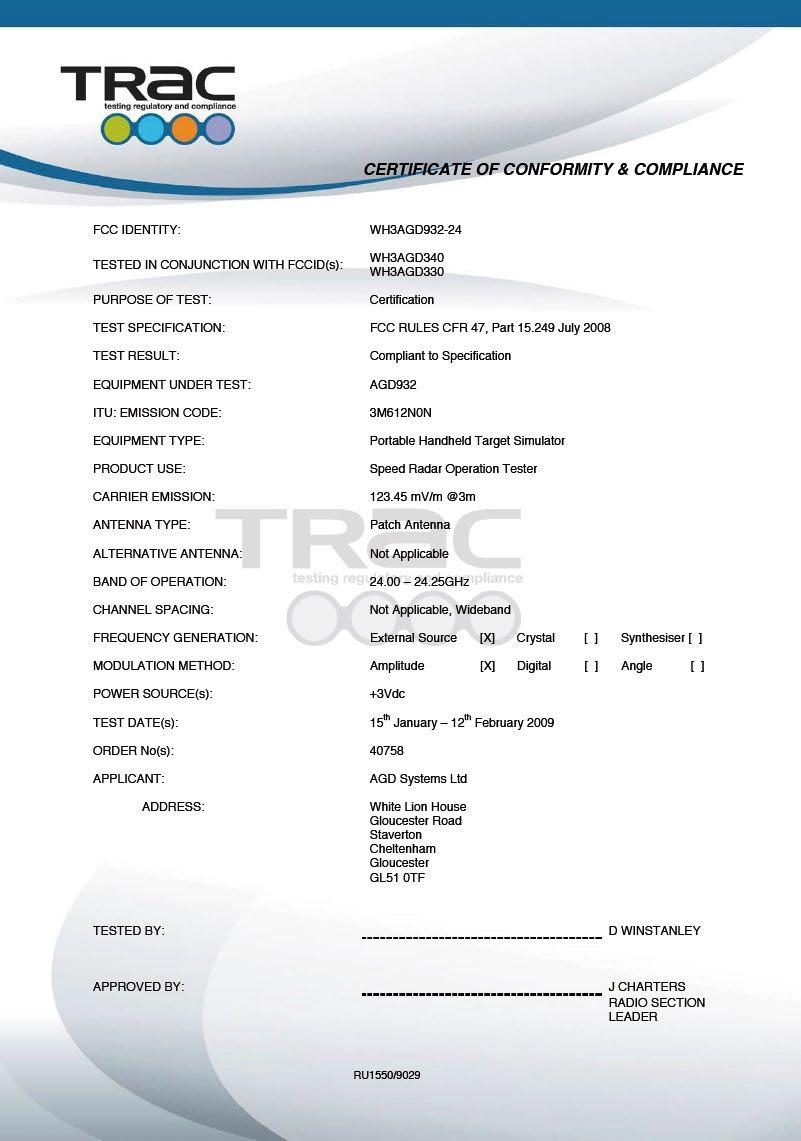
23 CERTIFICATION 23


24 IMPORTANT SAFETY INFORMATION SAFETY PRECAUTIONS All work must be performed in accordance with company working practices, in-line with adequate risk assessments. Only skilled and instructed persons should carry out work with the product. Experience and safety procedures in the following areas may be relevant: Working with mains power Working with modern electronic/electrical equipment Working at height Working at the roadside or highways 1. This product is compliant to the Restriction of Hazardous Substances (RoHS - European Union directive 2011/65/EU). 2. Only the specified access port should be used to access and replace batteries (2x AA). 3. The product must be correctly connected to the specified power supply. All connections must be made whilst the power supply is off or suitably isolated. Safety must take always take precedence and power must only be applied when deemed safe to do so. 4. No user-maintainable parts are contained within the product. Removing or opening the outer casing is deemed dangerous and will void all warranties. 5. Under no circumstances should a product suspected of damage be powered on. Internal damage may be suggested by unusual behaviour, an unusual odour or damage to the outer casing. Please contact AGD for further advice. 6. This device complies with part 15 of the FCC Rules. Operation is subject to the following two conditions: (1) This device may not cause harmful interference, and (2) This device must accept any interference received, including interference that may cause undesired operation. This equipment complies with FCC radiation exposure limits set forth for an uncontrolled environment. End users must follow the specific operating instructions for satisfying RF exposure compliance such that the module should not be installed in equipment intended to be used within 20cm of the body. The transmitter must not be co-located or operating in conjunction with any other antenna or transmitter. Changes or modifications not expressly approved by AGD Systems Ltd could void the user s authority to operate the equipment. 24
25 NOTES
26 NOTES
27 NOTES
28 DISCLAIMER While we (AGD Systems) endeavour to keep the information in this manual correct at the time of print, we make no representations or warranties of any kind, express or implied, about the completeness, accuracy, reliability, suitability or availability with respect to the information, products, services, or related graphics contained herein for any purpose. Any reliance you place on such information is therefore strictly at your own risk. In no event will we be liable for any loss or damage including without limitation, indirect or consequential loss or damage, or any loss or damage whatsoever arising from loss of data or profits arising out of, or in connection with, the use of this manual. WARRANTY All AGD products are covered by a 12 month return to factory warranty. Products falling outside this period may be returned to AGD Systems for evaluation, repair, update or re-calibration, any of which may be chargeable. AGD Systems Limited White Lion House T: +44 (0) Gloucester Road, F: +44 (0) Staverton, Cheltenham E: sales@agd-systems.com Gloucestershire, GL51 0TF, UK W: agd-systems.com ISO 9001 Registered Quality Management 015 ISO Registered Environmental Management 015 AGD Systems Limited 2016 Doc. Ref. 932 PM ISS3
PRODUCT MANUAL. AGD Systems Limited 2016 Doc. Ref. 206 PM ISS7 ISO ISO 9001 Registered Quality Management. Registered Environmental Management
 ISO 14001 PRODUCT MANUAL ISO 9001 Registered Quality Management 015 Registered Environmental Management 015 AGD Systems Limited 2016 Doc. Ref. 206 PM ISS7 TABLE OF CONTENTS INTRODUCTION Product & technology
PRODUCT MANUAL. AGD Systems Limited 2017 Doc. Ref. 316 PM ISS6 ISO ISO 9001 Registered Quality Management. Registered Environmental Management
 ISO 14001 PRODUCT MANUAL ISO 9001 Registered Quality Management 015 Registered Environmental Management 015 AGD Systems Limited 2017 Doc. Ref. 316 PM ISS6 TABLE OF CONTENTS INTRODUCTION Product & technology
HORNET Remote Control Systems
 HORNET Remote Control Systems Up to 100metres Range 1 3 Button versions 12-30Vdc 0r 230Vac versions Reliable FM Technology Up to four 1000W Relay switches Waterproof Receiver (IP68) Momentary or Latching
USER MANUAL MODEL: BM-162
 USER MANUAL MODEL: BM-162 Parents Unit: A. Name Power ON/OFF Key Music Key PTT Key Volume - Key Microphone Power & Low battery indicator LCD display Volume + Key Night Light and torch Key Speaker -Belt
FOBBER - FM Key Fob. Description. FM (FSK) Key fob Sleek and compact design Range up to 200metres 1-8 Switch variants 433 / 868MHz Options
 Key fob Sleek and compact design Range up to 200metres 1-8 Switch variants 433 / 868MHz Options") FOBBER - FM Key Fob FM (FSK) Key fob Sleek and compact design Range up to 200metres 1-8 Switch variants 433 / 868MHz Options Waterproof IP68 Rated CR2032 battery High Quality UK manufacture Can easily
FOBBER - FM Key Fob FM (FSK) Key fob Sleek and compact design Range up to 200metres 1-8 Switch variants 433 / 868MHz Options Waterproof IP68 Rated CR2032 battery High Quality UK manufacture Can easily
User's Manual. WM-294-V2 WLAN 11n USB module (1T1R) Version: 1.2. 晶訊科技股份有限公司 CC&C Technologies, Inc. Version 1.2 1
 Version: 1.2. 晶訊科技股份有限公司 CC&C Technologies, Inc. Version 1.2 1") User's Manual WM-294-V2 WLAN 11n USB module (1T1R) Version: 1.2 Manufacturer Version 1.2 1 Revision History Version Issue date Reason for revision 1.0 Mar. 02, 2015 First edition 1.1 Oct. 05, 2016 Modify
User's Manual WM-294-V2 WLAN 11n USB module (1T1R) Version: 1.2 Manufacturer Version 1.2 1 Revision History Version Issue date Reason for revision 1.0 Mar. 02, 2015 First edition 1.1 Oct. 05, 2016 Modify
WE-525T Antenna Analyzer Manual and Specification
 WE-525T Antenna Analyzer Manual and Specification 1.0 Description This product is designed to speed and ease the testing and tuning of antenna systems. Graphical displays of SWR, Return loss, Distance
Quick Start Guide. ELPRO 905U-L-T Wireless I/O Transmitter Unit. man_905u-l-t_quickstart_v1-7.doc
 Quick Start Guide ELPRO 905U-L-T Wireless I/O Transmitter Unit man_905u-l-t_quickstart_v1-7.doc ELPRO 905U-L-T Wireless I/O Transmitter Unit Quick Start Guide About this document This document is the ELPRO
SmartRadio control system
 AVO-ELITE SmartRadio control system Features 8 Channel transceiver module Range up to 1,000 metres 8 Digital outputs Minimal external components Secure data protocol Ultra low power 1.8-3.6V CE compliant
Quick Start Guide. ELPRO 905U-L-T Wireless I/O Transmitter Unit. man_905u-l-t_quickstart_v1.9.doc
 Quick Start Guide ELPRO 905U-L-T Wireless I/O Transmitter Unit man_905u-l-t_quickstart_v1.9.doc About this document This document is the and contains the following sections: Section Basic steps for using
ER200 COMPACT EMERGENCY CRANK DIGITAL WEATHER ALERT RADIO OWNER S MANUAL
 ER200 COMPACT EMERGENCY CRANK DIGITAL WEATHER ALERT RADIO OWNER S MANUAL Table of Contents -------------------------------------- 2 Features ----------------------------------------------- 3 Controls and
CRUX II/BTGPS USER GUIDE. Model:D1598
 CRUX II/BTGPS USER GUIDE Model:D1598 0 Federal Communication Commission Interference Statement This equipment has been tested and found to comply with the limits for a Class B digital device, pursuant
Houston Radar LLC. Installation and User Manual For. Doppler Radar DR-1500
 Houston Radar LLC Installation and User Manual For Doppler Radar DR-1500 Houston Radar LLC 13814 Sherburn Manor Dr. Cypress.TX Http://www.Houston-Radar.com Email: sales@houston-radar.com Contact: (281)
AM / FM RADIO TRANSMITTER KEYFOBS
 Highly Secure Protocol 1 3 Switch Options Led Indication Of Transmission Directly Compatible With Keeloq Decoder Power Saving Auto Shut Off Feature Automatically Transmits Battery Low Condition. User Customisable
Using the USB Output Port to Charge a Device
 Table of Contents ----------------------------------- 2 Features ----------------------------------------------- 3 Controls and Functions ---------------------------------- 4 ER210 Power Sources -----------------------------------
X80 Activator. User's Manual. Version 1.1.
 X80 Activator User's Manual Version 1.1 www.buckeyecam.com Table of Contents 1. Warnings... 3 2. Overview... 4 3. Getting Started... 5 4. Using the Activate Button... 7 5. Wiring... 8 6. Specifications...
Quick Start Guide. Antenna Alignment Tool AIMWLLR0-35. QSG rev 7 AIMWLLR0-35 [NRB-0200] QSG.indd 1
![Quick Start Guide. Antenna Alignment Tool AIMWLLR0-35. QSG rev 7 AIMWLLR0-35 [NRB-0200] QSG.indd 1](/thumbs/86/94268876.jpg "Quick Start Guide. Antenna Alignment Tool AIMWLLR0-35. QSG rev 7 AIMWLLR0-35 [NRB-0200] QSG.indd 1") Quick Start Guide Antenna Alignment Tool AIMWLLR0-35 QSG-00097 rev 7 AIMWLLR0-35 [NRB-0200] QSG.indd 1 Welcome This quick start guide is designed to familiarize you with the features and use of the NetComm
Quick Start Guide Antenna Alignment Tool AIMWLLR0-35 QSG-00097 rev 7 AIMWLLR0-35 [NRB-0200] QSG.indd 1 Welcome This quick start guide is designed to familiarize you with the features and use of the NetComm
System Requirements: D-Link Systems, Inc.
 System Requirements: Minimum System Requirements: CD-ROM Drive Computers with Windows, Macintosh, or Linux-based operating systems Installed Ether net Adapter Internet Explorer version 6.0 or Netscape
RCR-24 中文 GB. Version 1
 RCR-24 中文 GB Version 1 GB Please note not all AC adapters are alike. The AC adapter that is included with this radio is designed to be used exclusively with this device. Do not use an AC adapter that differs
Model RVM Portable Radar Wave Velocity Meter
 Model RVM Portable Radar Wave Velocity Meter Bulletin TE-RVM Specifications - Installation and Operating Instructions 3 [76.3] MENU SEL PWR RCL MODE 10 [250.8] 3-3/4 [9] 2-1/4 [5] The Model RVM Portable
Customizable Settings
 K40 RL360/RL200 QUICK REFERENCE GUIDE Customizable Settings To access and change any of the factory default settings: Press and hold VOLUME UP button for 3 seconds until Menu is announced. Press and release
Acu-Park TM. user s guide Directed Electronics, Inc. Vista, CA N9100T 09-04
 Acu-Park TM user s guide 2004 Directed Electronics, Inc. Vista, CA N9100T 09-04 limited one year warranty Directed Electronics, Inc. (hereinafter "Directed") promises to the original purchaser that this
User Manual Digital Wireless Rain Gauge
 Rain Gauge Specifications: User Manual Digital Wireless Rain Gauge - Outdoor rain gauge transmitter measures the rainfall and transmits the data to an indoor rain monitor base unit which shows the rainfall
ER200 COMPACT EMERGENCY CRANK DIGITAL WEATHER ALERT RADIO OWNER S MANUAL
 ER200 COMPACT EMERGENCY CRANK DIGITAL WEATHER ALERT RADIO OWNER S MANUAL Table of Contents -------------------------------------- 2 Features ----------------------------------------------- 3 Controls and
Wireless Pressure Station
 Wireless Pressure Station FORECAST RELATIVE PRESSURE PRESSURE HISTORY inhg -24h -18h -12h -9h- 6h -3h0 h INDOOR For online video support: http://bit.ly/laxtechtalk Model: 308-1417 DC: 111517 Table of Contents
SATELLITE RADIO OWNER'S MANUAL. Type III Radio
 SATELLITE OWNER'S MANUAL Type III Radio Table of Contents Congratulations!... 3 Operational Statement... 3 FCC Statement... 4 Activating Your Subscription... 5 Type III Radio... 6 Overview of Controls...
SYSTEM REQUIREMENTS (Windows) Windows XP(Service Pack 2 or later) or vista 3.2GHz Pentium 4 or faster Minimum 1GB of system RAM
 Windows XP(Service Pack 2 or later) or vista 3.2GHz Pentium 4 or faster Minimum 1GB of system RAM") CGO2 User Manual TABLE OF CONTENTS System requirements(windows) System requirements(mac) Technical specifications Introduction Overview Getting started Default camera settings Powering ON and OFF Camera
CGO2 User Manual TABLE OF CONTENTS System requirements(windows) System requirements(mac) Technical specifications Introduction Overview Getting started Default camera settings Powering ON and OFF Camera
CarConnect Bluetooth Interface General Motors Owner s Manual
 Bluetooth Interface General Motors Owner s Manual Introduction Thank you for purchasing the isimple CarConnect. The CarConnect is designed to provide endless hours of listening pleasure from your factory
BRAVO. SmartRadio Telemetry Module
 BRAVO SmartRadio Telemetry Module Features 8 Channel transceiver module Range up to 1,000 metres 8 Digital input/outputs Receiver outputs mirror transmitter inputs Minimal external components Secure data
9320 Manual Portable Battery Powered Indicator
 9320 Manual Portable Battery Powered Indicator Interface, Inc. 7401 E. Butherus Dr. Scottsdale, AZ 85260 800-947-5598 480-948-1924 (fax) www.interfaceforce.com CONTENTS INTRODUCTION...2 USER OPERATION...2
Evaluation Kit ATA8520-EK1-F and Extension Board ATA8520-EK3-F (US Version) Kit Content ATAN0157 APPLICATION NOTE
 Kit Content ATAN0157 APPLICATION NOTE") ATAN0157 Evaluation Kit ATA8520-EK1-F and Extension Board ATA8520-EK3-F (US Version) APPLICATION NOTE Kit Content The ATA8520-EK1-F kit includes the following components: Standalone board 902MHz antenna
ATAN0157 Evaluation Kit ATA8520-EK1-F and Extension Board ATA8520-EK3-F (US Version) APPLICATION NOTE Kit Content The ATA8520-EK1-F kit includes the following components: Standalone board 902MHz antenna
P700-WLS ioprox Receiver
 Installation Manual DN1628-1611 Pre-Installation Notes Copyright 2016 Tyco International Ltd. and its Respective Companies. All Rights Reserved. All specifications were current as of publication date and
KAPPA-T868SO. Smart Radio Telemetry Module
 KAPPA-T6 Smart Radio Telemetry Module Features Simple and low cost channel receiver module Range up to 500metres digital input/outputs Minimal external components Secure data protocol Ultra low power..6v
Grid Radar Installation Manual
 Grid Radar Installation Manual MODELS GN-RD-001 120V Single Phase / Wye, 240V Single Phase, with Neutral GN-RD-002 277V 3-Phase Wye, with Neutral GN-RD-003 480V 3-Phase Delta, no Neutral GN-RD-004 208V
Model 4105 Horn Antenna
 Model 4105 Horn Antenna System Settings and User Notes The Difference is the Data 13 Klein Drive, P.O. Box 97 North Salem, NH 03073-0097 Phone: (603) 893-1109 / Fax: (603) 889-3984 www.geophysical.com
AN0509 swarm API Country Settings
 1.0 NA-15-0356-0002-1.0 Version:1.0 Author: MLA Document Information Document Title: Document Version: 1.0 Current Date: 2015-04-16 Print Date: 2015-04-16 Document ID: Document Author: Disclaimer NA-15-0356-0002-1.0
TARGETuner Antenna Management System for Screwdriver Antennas
 TARGETuner Antenna Management System for Screwdriver Antennas www.westmountainradio.com 1020 Spring City Drive Waukesha, WI 53186 262-522-6503 sales@westmountainradio.com 2014, All rights reserved. All
OPERATING INSTRUCTIONS ARE ON PAGE 5. SECTION 2 Technical Data Transmitter Unit. RVHT 2 MULTI-FIT Programmable R/F Thermostat-Pair SECTION 1
 OPERATING INSTRUCTIONS ARE ON PAGE 5 RVHT 2 MULTI-FIT Programmable R/F Thermostat-Pair SECTION 1 This Programmable Ravenheat R/F controlled room Thermostat RVHT 2, consists of 2 items: a Mobile Transmitter
Wireless Pressure Station with Backlight
 Wireless Pressure Station with Backlight FORECAST RELATIVE PRESSURE PRESSURE HISTORY inhg -24h -18h -12h -9h- 6h -3h0 h INDOOR For online video support: http://bit.ly/laxtechtalk Model: 308-1417BL DC:
Applicable for the following PLC UV Head Controller model: PLC R
 OmniCure PLC 2000 User Guide Applicable for the following PLC UV Head Controller model: Model Part Numbers PLC2000 019-00214R Excelitas Canada Inc. 2260 Argentia Road Mississauga (ON) L5N 6H7 Canada +1
DIVERSE MAGMETER MF500M+ USER MANUAL. Contents INTRODUCTION FIRST TIME - QUICK START OPERATION OPERATION - OPTIONS MAGNETITE METER
 Contents DIVERSE MAGMETER MF500M+ INTRODUCTION FIRST TIME - QUICK START OPERATION OPERATION - OPTIONS MAGNETITE METER CALIBRATION AND PIPE OCCLUSION MEASUREMENT TECHNIQUE SPECIFICATION USER MANUAL LIABILITY
Manual Unihan UPWL6025
 Manual Unihan UPWL6025 Federal Communications Commission Statement This device complies with FCC Rules Part 15. Operation is subject to the following i. This device may not cause harmful interference,
User Manual Information and Product Description. of the. Flap Key Family BOSCH. with Chevy, GMC and GM Logo
 User Manual Information and Product Description of the Flap Key Family BOSCH with Chevy, GMC and GM Logo Page 1 of 7 General Description of the RF transmitter: The RF remote control system consists of
Sense. 3D Scanner. User Guide. See inside for use and safety information.
 Sense 3D Scanner User Guide See inside for use and safety information. 1 CONTENTS INTRODUCTION.... 3 IMPORTANT SAFETY INFORMATION... 4 Safety Guidelines....4 SENSE 3D SCANNER FEATURES AND PROPERTIES....
Trap Series. Features: Description. Technologically Advanced: 2Km Range Protective Rubber Boot 1, 4 and 16 Switch versions
 Trap Series Features: Waterproof Receiver IP68 One Transmitter to Many receivers Robust and reliable Technologically Advanced: 2Km Range Protective Rubber Boot 1, 4 and 16 Switch versions The TRAP system
Mag 3/6 System. Manual.
 Mag 3/6 System Manual www.undergroundmagnetics.com 1: Introduction....1 1 2: Caution.... 2 2 3: FCC Compliance Statement.. 3 4: Tips for Reading this Manual....3 4 5: Preface....4 5 6: System Highlights....6
Arduino Arduino RF Shield. Zulu 2km Radio Link.
 Arduino Arduino RF Shield RF Zulu 2km Radio Link Features RF serial Data upto 2KM Range Serial Data Interface with Handshake Host Data Rates up to 38,400 Baud RF Data Rates to 56Kbps 5 User Selectable
Model: WS-7014CH-IT Instruction Manual DC: WIRELESS FORECAST STATION
 Model: WS-7014CH-IT Instruction Manual DC: 081815 WIRELESS FORECAST STATION Date Time + WWVB Indoor Temperature, Humidity + Comfort Forecast + Tendency Outdoor Temperature ºF/ºC + Channel Indicator Base
User s Guide FM Transmitter
 TM 12-634 User s Guide FM Transmitter Please read this user s guide before using your new FM Transmitter. 12-634_en.indd 1 Package contents FM Transmitter USB Cable User s Guide Quick Start IMPORTANT SAFETY
RFTX-1 Installation Manual
 RFTX-1 Installation Manual complete control Universal Remote Control RFTX-1 Installation Manual 2009-2014 Universal Remote Control, Inc. The information in this Owner s Manual is copyright protected. No
Installation & Operation Manual SAGA1-K Series Industrial Radio Remote Control
 Installation & Operation Manual SAGA1-K Series Industrial Radio Remote Control Gain Electronic Co. Ltd. Table Of Contents Safety Considerations ------------------------------------------------------------2
User's Manual F10G-5S-LCD 1 / 20 BOOST CELL PHONE SIGNAL BOOSTERS MADE BY HUAPTEC
 User's Manual F10G-5S-LCD 1 / 20 BOOST CELL PHONE SIGNAL BOOSTERS MADE BY HUAPTEC Table of contents WHAT IS INCLUDED... 3 1 HOW IT WORKS... 3 2 TOOL REQUIRED... 3 3 HOW TO INSTALL YOUR NEW CELLULAR BOOSTER...
Remote Control Outlets Operating Instructions
 Remote Control Outlets Operating Instructions - FOR INDOOR OR OUTDOOR USE - IMPORTANT SAFEGUARDS Signal Word Definitions NOTE: These are general definitions only; all may not pertain to the actual product
Radio Frequency Exposure Test Report
 Radio Frequency Exposure EN 62311 January 2008 Assessment of electronic and electrical equipment related to human exposure restrictions for electromagnetic fields (0Hz 300GHz) (IEC 62311:2007, modified)
Connevans.info. DeafEquipment.co.uk. This product may be purchased from Connevans Limited secure online store at
 Connevans.info Solutions to improve the quality of life Offering you choice Helping you choose This product may be purchased from Connevans Limited secure online store at www.deafequipment.co.uk DeafEquipment.co.uk
Product Manual. Getting Started with Roadie 2.
 MOL NUMBER RD200 Product Manual Getting Started with Roadie 2. This manual is a quick start guide for Roadie 2. Please read the following instructions and conditions before using Roadie 2. For a more comprehensive
OPERATION MANUAL WARNING
 TM OPERATION MANUAL WARNING TO REDUCE THE RISK OF INJURY OR PRODUCT DAMAGE, READ OPERATION MANUAL PRIOR TO OPERATING PRODUCT. PATENT PENDING - COPYRIGHT 2014 - APPION INC. - ALL RIGHTS RESERVED Introduction
K40 Consult. Don t like to read manuals? Call our experienced K40 Consultants. We ll explain the whole thing
 K40 Consult Don t like to read manuals? Call our experienced K40 Consultants. We ll explain the whole thing. 800.323.5608 K40 ELECTRONICS 600 Tollgate Rd., Suite A Elgin, IL 60123 www.k40.com Table of
Connected Cooler Radio. Quick Start Guide
 Connected Cooler Radio Quick Start Guide Table of Contents 1. GETTING STARTED... 5 1.1 UNPACKING INFORMATION... 5 1.2 INTRODUCTION... 5 2. PORTS AND LED INDICATORS... 6 2.1 PORTS... 6 2.2 LED INDICATORS...
SOM i.mx6. Regulation Information. Simple. Robust. Computing Solutions. Rev 1.1
 SOM i.mx6 Regulation Information Rev 1.1 Simple. Robust. Computing Solutions SolidRun Ltd. 7 Hamada st., Yokne am Illit, 2495900, Israel www.solid-run.com 1 Page Document revision 1.1 24052018 SolidRun
Internal B-EN Rev A. User Guide. Leaf Aptus.
 User Guide Internal 731-00399B-EN Rev A Leaf Aptus www.creo.com/leaf Copyright Copyright 2005 Creo Inc. All rights reserved. No copying, distribution, publication, modification, or incorporation of this
STAFF User Manual. Manual Part #
 STAFF User Manual Manual Part # 030-00085-00 Introduction Congratulations on the purchase of your new STAFF Secondary Fault Locator. The STAFF is specially designed to detect conductor to earth/ground
K40 Consult. Don t like to read manuals? Call our experienced K40 Consultants. We ll explain the whole thing
 K40 Consult Don t like to read manuals? Call our experienced K40 Consultants. We ll explain the whole thing. 800.323.5608 K40 ELECTRONICS 600 Tollgate Rd., Suite A Elgin, IL 60123 www.k40.com Table of
M508 GPS Tracking Device
 M508 GPS Tracking Device (GPS+GPRS+GSM) Product Manual Edition 1.3 Copyright 10 th Oct., 2009 GATOR GROUP CO.,LTD. All rights reserved. http://www.gatorcn.com China Printing ADD: 312# Ansheng Building,Xixiang
Owner s. Manual. Expand Your Factory Radio. Honda/Acura. Media GateWay PXAMG. HD Radio Operation. isimple Connect
 Expand Your Factory Radio Honda/Acura Owner s HD Radio Operation Manual isimple Connect Media GateWay PXAMG isimple A Division of AAMP of America 13190 56th Court Clearwater, FL 33760 Ph. 866-788-4237
PTT- Z or PTT-U PUSH-TO-TALK Specification
 Federal Communication Commission Interference Statement This equipment has been tested and found to comply with the limits for a Class B digital device, pursuant to Part 15 of the FCC Rules. These limits
DTR Frequently Asked Questions (FAQ) LEAFLET
 LEAFLET") DIGITAL TWO-WAY RADIO DTR Frequently Asked Questions (FAQ) LEAFLET April 2019 2019 Motorola Solutions, Inc. All rights reserved. *MN005512A01* MN005512A01-AA Contents Product Safety and RF Exposure Compliance...3
DIGITAL TWO-WAY RADIO DTR Frequently Asked Questions (FAQ) LEAFLET April 2019 2019 Motorola Solutions, Inc. All rights reserved. *MN005512A01* MN005512A01-AA Contents Product Safety and RF Exposure Compliance...3
Appearance of device and accessories may vary.
 Mobile 4G Smart Technology Signal Booster Contents: How it Works.... 1 Before Getting Started.... 2 Quick Installation Overview.... 2 Installing the Outside Antenna.... 2 Installing the Low-Profile Antenna....
Operator s Manual for Your Wireless Leash Guidance Trainer Series
 Operator s Manual for Your Wireless Leash Guidance Trainer Series Congratulations! The Unleashed Technology Wireless Leash Guidance Trainer Series you have purchased is a step forward in technology and
ALPHA meter. General. Installation instructions IL S
 Installation instructions IL4-400S General This instructional leaflet contains general installation instructions for the following single phase and polyphase watthour meters: socket-connected meters: S,
Operating Instructions
 3000 Operating Instructions Contents Introduction 1 Operating Instructions 2-4 Demonstrations 5-6 Storing/Handling/Cleaning 7 Safety Precautions 7-8 Specifications 8 FCC Compliance Statement 9-10 Limited
WS-7220U-IT 915 MHz Wireless Weather Station. Instruction Manual
 WS-7220U-IT 915 MHz Wireless Weather Station Instruction Manual 1 TABLE OF CONTENTS Introduction..3 Inventory of Contents 4 Quick Set Up 4 Detailed Set Up 4-5 Battery Installation....4-5 12 or 24 Hour
Radio Controlled timekeeping. Receives 60KHz WWVB signal transmitted by NIST in Fort Collins, Colorado
 Congratulation on your purchase of an Atomix Radio Controlled clock. Radio Controlled technology allows for the most accurate time keeping available as well as automatic changes for Daylight Saving Time
EA200 uhf EA200 vhf User Guide
 EA200 uhf EA200 vhf User Guide 1 2 TABLE OF CONTENTS RF Safety & FCC... 4 Safety & Information... 5 Electromagnetic Interference Compliance... 6 Industry Canada Compliance... 7 Computer Software Copyrights...
DSi dual readhead rotary encoder system
 Installation guide M-9653-9298-01-A RSLM high accuracy linear encoder DSi dual readhead rotary encoder system Renishaw plc declares that TONiC encoder system complies with the applicable standards and
Manual Unihan UPWL6580
 Manual Unihan UPWL6580 Federal Communications Commission Statement This device complies with FCC Rules Part 15. Operation is subject to the following i. This device may not cause harmful interference,
3G Mini-Card Gobi2000
 Fujitsu America, Inc. 3G Mini-Card Gobi2000 Regulatory and Safety Information Please read this document carefully prior to using the 3G Mini-Card Gobi2000 modem in your Fujitsu LifeBook. Important notice
ANTENNA DESIGN GUIDE. Last updated February 11, The information in this document is subject to change without notice.
 TIWI-UB2 Last updated February 11, 2016 330-0106-R1.2 Copyright 2012-2016 LSR Page 1 of 21 Table of Contents 1 Introduction... 3 1.1 Purpose & Scope... 3 1.2 Applicable Documents... 3 1.3 Revision History...
Atomic Forecast Station with Moon Phase
 Atomic Forecast Station with Moon Phase For online video support: http://bit.ly/laxtechtalk Model: S84107 Instruction Manual DC: 080817 Welcome to the La Crosse Technology family! We hope you enjoy your
BOOMERANG PAGING SYSTEM (RCL T800) Manual
 Manual") BOOMERANG PAGING SYSTEM (RCL T800) Manual RCL Korea A. EASY INSTALLATION INSTRUCTION Step Lock the antenna to the right corner of the Boomerang RCL T800 Transmitter. (Fit over plug and twist left to lock
BOOMERANG PAGING SYSTEM (RCL T800) Manual RCL Korea A. EASY INSTALLATION INSTRUCTION Step Lock the antenna to the right corner of the Boomerang RCL T800 Transmitter. (Fit over plug and twist left to lock
Laser User Manual. Therapy Unit INTRODUCTION
 INTRODUCTION The Laserex Laser 3000 is a highly versatile and compact laser therapy device that, under the guidance of a qualified Veterinarian, provides a simple method of treatment, delivering relief
Wireless Z-Wave Control ZRP-100US Z-Wave Repeater USER MANUAL. Introduction
 Wireless Z-Wave Control ZRP-100US Z-Wave Repeater USER MANUAL Introduction Thank you for choosing ZRP-100 Z-Wave Repeater product! ZRP-100 is a Z-Wave repeater with best RF performance to repeat Z-Wave
WEB I/O. Wireless On/Off Control USER MANUAL
 Wireless On/Off Control Technical Support: Email: support@encomwireless.com Toll Free: 1 800 617 3487 Worldwide: (403) 230 1122 Fax: (403) 276 9575 Web: www.encomwireless.com Warnings and Precautions Warnings
COD GB / 1.0 RBAND/UMS - RBAND/CSM
 INTRODUCTION DESCRIPTION The RadioBand system is designed of Industrial, Commercial and Domestic door and gate applications where a safety edge is used. The system provides a wireless system replacing
GRX Online Retroreflectivity Sensor User Manual
 GRX Online Retroreflectivity Sensor User Manual Online sensor for production line control of the retroreflection properties of traffic sign sheeting materials. Manual August 2018 ver. 1.2 - English DELTA
PRODUCT MANUAL VEHICLE DETECTION. Traffic Management Radar. AGD Systems Limited 2016 Doc. Ref. 350 PM ISS3 CERTIFIED ISO 14001
 ISO 14001 350 VEHICLE DETECTION CERTIFIED Traffic Management Radar 350 PRODUCT MANUAL ISO 9001 Registered Quality Management 015 Registered Environmental Management 015 AGD Systems Limited 2016 Doc. Ref.
Quick Start Guide. ELPRO 105U-L-T Wireless I/O Transmitter Unit. man_105u-l-t_quickstart_v1-8.doc
 Quick Start Guide ELPRO 105U-L-T Wireless I/O Transmitter Unit man_105u-l-t_quickstart_v1-8.doc ELPRO 105U-L-T Wireless I/O Transmitter Unit Quick Start Guide About this document This document is the ELPRO
Installation Instructions
 Installation Instructions Garage Door Opener Radio Controls Model 5010 (300 mhz) \ 5012 (310 mhz) Single Button Transmitters Model 5100-01 (300 mhz) \ 5102-01 (310 mhz) Receivers WARNING: Disconnect operator
Multi-Channel In-Out Thermometer with Cable Free Sensor and RF Clock
 Multi-Channel In-Out Thermometer with Cable Free Sensor and RF Clock MAIN FEATURES: MAIN UNIT GB MODEL: RMR182 USER'S MANUAL INTRODUCTION Congratulations on your purchase of the RMR182 Multi- Channel In-Out
Contents. Page English 1. French. Spanish. Reset of MIN/MAX records 915 MHz Reception Mounting Care and Maintenance Warranty Information
 Contents Language Page English 1 French Spanish WIRELESS 915 MHz TEMPERATURE STATION Instruction Manual TABLE OF CONTENTS Topic Page Inventory of Contents Features Setting Up Battery Installation Function
802.11n, 2.4G 1T1R Wireless LAN PCI Express Half Mini Card
 802.11n, 2.4G 1T1R Wireless LAN PCI Express Half Mini Card WN6605LH Realtek RTL8191SE User s Manual Ben J. Chen 3/4/2010 Federal Communication Commission Interference Statement This equipment has been
Convey-All BTS 550 Wireless Seed Tender Remote Users Manual
 Convey-All BTS 550 Wireless Seed Tender Remote Users Manual Intercomp Co. 3839 County Road 116 Medina, MN 55340, U.S.A. (763)-476-2531 1-800-328-3336 Fax: 763-476-2613 www.intercompcompany.com Manual#
PYRAMID 915MHZ WIRELESS RF TRANSMITTER & REPEATER USER GUIDE. Table of Contents. Overview Installation Setup Specifications...
 Table of Contents Overview................................... 1 Installation.................................. 1 Setup...................................... 2 Specifications..............................
P700WLS IoProx Receiver
 Installation Manual Warning! This manual contains information on limitations regarding product use and function and information on the limitations as to liability of the manufacturer. The entire manual
User's Guide. Wireless AC Circuit Identifier. Models RT30 and RT32
 User's Guide Wireless AC Circuit Identifier Models RT30 and RT32 Introduction Congratulations on your purchase of Extech s Model RT30 (914Mhz) or RT32 (869MHz) Wireless AC Circuit Identifier. The detector
SKY LF: 300 khz 3 GHz Medium Power GaAs SPDT Switch
 DATA SHEET SKY13268-344LF: 3 khz 3 GHz Medium Power GaAs SPDT Switch Applications Transceiver transmit-receive switching in GSM, CDMA, WCDMA, WLAN, Bluetooth, Zigbee, land mobile radio base stations or
CCR24T CCR24R. User s Guide WIRELESS TRANSMITTER SYSTEM WARRANTY SERVICE CARD WARRANTY CARD
 WARRANTY SERVICE CARD WARRANTY CARD PRODUCT NAME Wireless Transceiver System PERIOD MODEL NAME CCR24GEN YEAR PURCHASE DATE.. 200_ From the date of WARRANTY PERIOD.. 200_ purchase. CUSTOMER S ADDRESS :
USER MANUAL Digital Wireless Gateway U9120-W4 (P/N: 44002G-01)
") USER MANUAL Digital Wireless Gateway U9120-W4 (P/N: 44002G-01) 19549P-82 (11-16) 2016 DAVID CLARK COMPANY INCORPORATED Cautions and Warnings READ AND SAVE THESE INSTRUCTIONS. Follow the instructions in
USER MANUAL Digital Wireless Gateway U9120-W4 (P/N: 44002G-01) 19549P-82 (11-16) 2016 DAVID CLARK COMPANY INCORPORATED Cautions and Warnings READ AND SAVE THESE INSTRUCTIONS. Follow the instructions in
What is Moto? bring happiness to life. The lights Pressuresensitive
 User Manual 1 bring happiness to life What is Moto? Moto tiles are a tool for physical play. They are included under the product category Playware, which combines robotics with play to create products
WLS-5500 Receiver (KSF & W26)
") WLS-5500 Receiver (KSF & W26) Installation Manual DN1869-0912 Warning! This manual contains information on limitations regarding product use and function and information on the limitations as to liability
WLS-5500 Receiver (KSF & W26) Installation Manual DN1869-0912 Warning! This manual contains information on limitations regarding product use and function and information on the limitations as to liability