National Instruments Switches
|
|
|
- Eugene Parks
- 6 years ago
- Views:
Transcription
1 ni.com

2 National Instruments Switches Raviteja Chivukula
3 Webinar Overview A. Switch Basics A. Recap B. Advanced Switch Topics A. High Channel Switches B. Fault Insertion Units C. Resistor Modules D. RF Switching E. Considerations while using Switch Matrix C. Switch Executive 3
4 Switch Basics
5 Need for Switches Single measurement device Multiple measurement points Nearly every system can benefit from switching Increases channel count Adds measurement flexibility Simplifies test fixture Decreases cost Test Instruments Test Points Solution Stimulus/Resp 1 Digitizer, 1 Arb 20 DUTs SWITCHING Temperature 1 DMM 200 RTDs SWITCHING 5
6 Test Architecture DMM Switch Hardware Devices Under Test Digitizer Arb/FunctGen Power Supply Matrix Gen. Purpose RF Analyzer RF Generator Mux 6


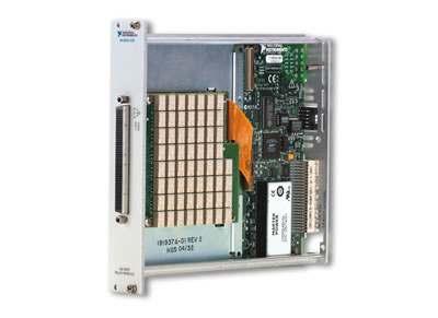
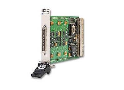
7 Controlling NI Switches: PXI Options Embedded controller MXI Connector Kit 7
8 Specifications of a typical matrix card Switch Type Matrix Max Switching Voltage DC 12 VDC Maximum Switching Voltage AC 8 VAC Max Switching Current 100 ma Maximum Carry Current 100 ma Maximum Switching Power 1.2 W Bandwidth 1 MHz Relay Type FET Path Resistance (Typical) 9 Ohm Thermal EMF 10 µv Scan Rate cycles/s Matrix Config Wire Mode 1-wire Matrix Config Banks 1 8
9 Advanced Switch Topics
10 High Channel Switches Channel Expansion

11 Why expansion? Extremely high channel counts Strain Measurements on large structures Vibration measurements on large structures etc. 11


12 Current Large Matrix Solution PXI Crosspoints Supported topologies 4 x x x 32 12
13 Creating Larger Matrices / Switches / FIUs Multiple connected 2532s 13


14 Creating Larger Matrices / Switches / FIUs 14

15 PXI Expansion: Matrices Expand the PXI-2529 columns using the TB Connect adjacent terminal blocks with ribbon cables Example: PXI
16 Two 4x6 Switch Modules -> One 4x12 16


17 PXI Expansion: Multiplexers Expansion in Multiplexer mode is possible using analog bus expansion connectors in front of TB TB-2605 Example: PXI


18 PXI Expansion: Matrices Column expansion using SHC68-C68-S cable No row expansion Example: PXI
19 Fault Insertion Units


20 Fault Insertion Unit (FIU) Simulate open, pin-to-pin, short-tobattery, and short-to-ground faults Application Hardware In Loop Testing Used to introduce faults between Controller & Sensor NI 2510, NI 2512 etc. 20
21 FIU Topology Sensor 1 Sensor 2 Controller 21
22 FIU Pass-through Mode 22
23 FIU Open-circuit Fault 23
24 FIU Short to GND / Short to PWR 24
25 FIU Pin to Pin shorts 25
26 272x Resistor Modules
 Pink relay: Bridge relay between two banks Not shown: Test relay to connect to front test connector.")
27 272x Design Overview Green relays: Each bank contains 8 bit relays (16 bit banks are 2x8) Red relay: Infinite resistance (open) Orange relay: ~0 Ohms (short) Pink relay: Bridge relay between two banks Not shown: Test relay to connect to front test connector. 27

28 272x Design Overview (cont) By switching the green relays, you decrease the resistance of the path. Resistor values don t match exact binary values Manufacturing differences Temperature offset Trace and Relay offsets NOT able to be calibrated Used to replicate RTDs / other sensors, used for load testing, etc 28
29 NI 272x Applications RTD Simulation Other Sensor Simulation Resistive Load Simulation etc. 29
30 272x - Switch Programming Appears like any other switch Has appropriately named channels Connection and Relay Control APIs both work connect b6->b6r0 vs. close kb6r0 Can use DAQmx, IVI, NI-SWITCH, NI Switch Executive as a switch device in independent topology. NI Recommends the 272x Reference Vis 30
31 NI 272x - Reference VIs Programming Session Based Resistance Based Set Channel 2 to be 100 Ohms Installed by Installer Ensures DAQmx Core Product version > 9.5 installed Ships with readme and a PDF Does NOT need NI-SWITCH installed example finder support (Help >> Find Examples...) VI palettes to Instrument Control error code strings custom session handle to follow session paradigm from other MI drivers 31


32 272x Example Block Diagram 32
33 RF Switch Concepts 33
34 NI RF Switch Products Bandwidth MHz 500 MHz 2.7 GHz 2.7 GHz 6.6 GHz 26.5 GHz 40 GHz 500 MHz 50 switches 4 topologies available 2.5 GHz 75 switches 2.7 GHz 50 switches 6 topologies available 5 GHz 50 4x1 mux 6.6 GHz 50 SSR 26.5 GHz 50 switches 40 GHz 50 switches 4 topologies available 21 total modules available 34
35 RF Switching Specifications Maximum Bandwidth Insertion Loss VSWR Characteristic Impedance Crosstalk/Isolation Termination Signal Characteristics (Sine or Square, Rise Time, etc.) Channel Density Maximum Power 35
36 What is Insertion Loss? Source P in P out Load 50Ω Z o =50Ω 50Ω Insertion Loss (db) = 10 * log 10 ( P out / P in ) 36
37 Why Does Insertion Loss Occur? V in Module ground R V out = Vin in C ω R 2 C V out 2 Ideal Switch But in reality, switch looks more like this C = Net Capacitance of Circuit R = Path Resistance of Switch Insertion loss measures attenuation and power loss induced by switch For ideal DC systems, ω=0, therefore V out = V in Loss is higher at higher frequencies 37
38 Voltage Standing-Wave Ratio (VSWR) When waves propagate between mediums, reflections occur (wave theory) VSWR is a measure of this reflection Sound wave example Greater the variation in mediums, greater the reflection Air Reflected (ECHO) Wall Propagated 38
39 Facts About VSWR In electrical systems, reflections occur when signal propagates through components with varying characteristic impedances (connectors, relays, traces, etc.) VSWR measures the power of this reflected signal VSWR is an important consideration in systems where signal reflections can damage the source 39
40 Characteristic Impedance To minimize reflections, RF components are designed to have a certain per unit length impedance or characteristic impedance Characteristic impedance is not a DC resistance!!! Almost all RF systems have characteristic impedance of either 50 or 75 Ω To minimize reflections and maximize amount of power transferred from source to load transmitted, impedance of all components in RF system must be matched Source 50Ω P in P reflected Z o 50Ω P out Load 50Ω P in = P out and P reflected = 0 Matched 50 System (Ideal) 40
41 Calculating VSWR VSWR = Voltage Standing Wave Ratio VSWR is the ratio of the maximum to minimum voltage in the standing wave pattern on the transmission line Z O Impedance Discontinuity 1+ Γ VSWR = 1 Γ Z Where, Γ = Z L L Z + Z O O Z L Mismatched RF system 41
42 Example : VSWR In Phase: 180 Out of Phase: 1V p-p Incident Wave (20mW) Source 40.5Ω Z o =40.5Ω 100mV p-p Reflected Wave (0.2mW) 50Ω Maximum - In phase : 1.1V p-p Minimum Out of Phase: 0.9V p-p 42
43 Example : VSWR In phase: 1.1V p-p 180 Out of Phase: 0.9V p-p METHOD 1 METHOD 2 Ratio of maximum to minimum voltage in the standing wave pattern on the transmission line VSWR = 1.1V 0.9V p p p p = 1.22 VSWR formula calculation Γ = VSWR = 1 = =
44 Crosstalk / Isolation Crosstalk: When an unwanted signal is coupled from one circuit to another. Example: Between 2 banks on switch module Isolation: When an unwanted signal is coupled across an open circuit. Example: open relay COM1 COM2 Signal carried over between two independent circuits COM1 Signal carried over open relay 44
45 Termination DUT1 50Ω 50Ω Transmission Line Z o =50Ω Load DUT 1 (50 ) 50Ω RFSA DUT8 50Ω Z o =50Ω DUT 8 (50 ) Medium change causes the majority of the signal to reflect In the case of DUT1, the entire signal route has a characteristic impedance of 50Ω In the case of DUT8, the open relay causes a break in the 50Ω characteristic impedance of the circuit which results in reflections R Air 45
46 Termination (cont) DUT1 50Ω 50Ω Transmission Line Z o =50Ω Load DUT 1 (50 ) 50Ω RFSA DUT4 50Ω Z o =50Ω DUT 4 (50 ) Termination resistor keeps reflections low 50Ω Termination is VERY crucial when the DUT is: Continuously generating signal Sensitive to signal reflections 46
47 Rise Time Time required for output signal voltage to rise from 10% to 90% Important specification when routing square waves Can be used to approximate 3 db point of switch (bandwidth) To route a square wave accurately, the bandwidth of the switch should be 7 times the frequency of the signal τ = 0.35 Bandwidth 47
 Slower")


48 Rise Time (cont) Slower Faster rise time RiseTime ( τ ) = 0.35 Bandwidth 5 MHz Square Wave with MHz Digitizer 48
49 Considerations while using Switch Matrix
50 Switching Low-Voltage Signals (< 1 mv) Thermal EMF Dissimilar metals create a voltage drop at their junction Typical o Electromechanical: 1-10 uv o Reed: uv Junction Creates a thermocouple that varies voltage offset with temperature Copper-Nickel 0.5 µv/ C Copper-Copper <0.3 Copper-Gold 0.5 Copper-Silver 0.5 Copper-Brass 3 Copper-Lead-Tin Solder 1-3 Copper-Aluminum 5 Copper-Kovar 40 Copper-Copper Oxide >500 50
51 Switching Low-Voltage Signals (< 1 mv) (cont) Minimize the effects of Thermal EMF by using 2-wire topologies 1-wire mode 2-wire mode µv + DUT - DMM µv + + DUT µv DMM - If DUT = 5 µv Switch thermal emf = 2.5 µv DMM measures between 2.5 and 7.5 µv Measurement error = 50% DUT = 5 µv, Switch thermal emf = ± ( µv) DMM measures between 4.8 and 5.2 µv Measurement error = 4% 51
52 Switching Low Currents (< 10 μa) Leakage Currents Can leak to: Leakage to ground i L Relay Channel-to-ground leakage Channel-to-channel leakage V s R Leakage To DMM Ch0 i L C G i leakage R surface Channel-to-Channel leakage Ch1 C c 52
53 Switching Low Currents (< 10 μa) (cont) Minimizing leakage currents Calibrate your system: Apply step voltage to each individual channel Choose the a switch with high isolation & low leakage o FET/SSR switches have leakage current injected from the relay itself Isolate sensitive signals from switch system (use PXI-4022 guard card) i test - i leakage HI Sense DUT HI DMM i test Guard + - i leakage Test Fixture LO Sense LO Guarding 53
54 Switching Low Currents (< 10 μa) (cont) Triboelectric Currents Generated by charge that builds due to friction between conductor and insulator on cable Occurs when cables are bent or moved excessively Can be minimized by tying cables down Electrostatic Interference High-impedance circuitry is susceptible to pick up noise Effective shielding of the DUT and cables can help reduce this noise Settling Time When relay is closed it bounces before making a connection. This causes a charge transfer which gives rise to a current pulse What happens when ball is dropped on ground? Error can be minimized by taking a measurement after settling time of switch has elapsed 54
55 Measuring Low Capacitance with Switches When performing Low Capacitance measurements, the switch cannot add additional error. Selecting the right topology for these measurements reduces added capacitance SPDT Matrix Select switches with: Low path resistance Low minimum current. Perform averaging on DMM. Perform Open / Short Compensation on DMM 55
56 Other Examples Switching Inductive Loads Use MOV and FlyBack diode to reduce voltage spikes Switching Capacitive Loads Use resistor in series to prevent inrush current DMM is a capacitive load! Low current / voltage Hot Switching Pay attention to minimum switching load spec. All Armature Relays have this problem 56
57 NI Switch Executive
58 Modular Test Architecture Test Management Services TestStand Test Modules Switch Management Software NI Switch Executive Measurement Services Unit Under Test Switch Hardware 58
59 Key Benefits to Switch Management SW Abstraction of low-level switch programming details Reuse and easily maintain test modules o Create test modules with generic switching calls (ex. connect TestUUT1 ) o For new tests, reuse existing modules and create new NISE configuration Multimodule integration Create a virtual switch device integrating multiple switches NISE API treats virtual device as a single switch Automatic routing Assists in creating routes across one or several switch modules 59
60 NI Switch Executive Accessed via MAX Operates as a configuration utility Built on top of the IVI switch class driver Provides a bridge between the driver level and the ADE level Is integrated with LabVIEW, LabWindows/CVI, C/C++, Visual Basic and TestStand Provides support functions within these environments to utilize Virtual Devices created within NISE Easily deployable to other systems Includes hardware protection features 60


61 System Level Switch Management Software NI Switch Executive Visual Route Editor Supports common and custom topologies Multi-module configuration End-to-end routing System validation Automated configuration export and system documentation 61


62 Supports NI and 3 rd Party Switch Hardware Built on top of the IVI Switch Class Driver Integrates ANY IVI compliant switch IVI Driver development assistance available through NI 62
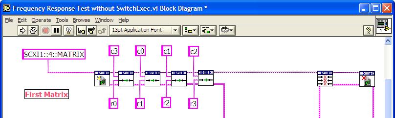

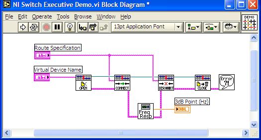
63 Seamless Integration With LabVIEW BEFORE AFTER 63

64 NI Switch Executive in TestStand Seamless integration with NI TestStand Occurs before all other items in step 64
65 Summary Greatly simplify switch programming with switch management software Multimodule integration Automatic routings Channel aliases, routes and route groups Abstract low-level programming for code reuse and maintenance Build scalable switch solutions with modular switch software Open, modular switch platform Multiple topology devices System and module level switch software 65
National Instruments Switches
 ni.com National Instruments Switches Raviteja Chivukula Why the Need for Switches? Nearly every system can benefit from switching Increases channel count Adds measurement flexibility Simplifies test fixture
Fallstricke präziser DC- Messungen
 Fallstricke präziser DC- Messungen Sascha Egger, Applications Engineer Group Leader National Instruments Switzerland GmbH Agenda Overview of Precision Test Systems Techniques for: Low-voltage measurements
white paper A primer A utomated Signal Switching reliable data first time every time
 white paper A utomated Signal Switching 1 Overview Routing electrical and even optical signals from one source to another requires an overall understanding of the application, signals being switched and
2.5 GHz 75 Ω Multiplexer and SPDT Relay Switches
 2.5 GHz Multiplexer and SPDT Relay Switches NI PXI-255x NEW! 2.5 GHz bandwidth characteristic impedance 30 V max switching voltage 0.5 A max switching current 10 W max switching power Mini SMB direct connectivity
A GREATER MEASURE OF CONFIDENCE. Switching. Handbook. A Guide to Signal Switching in Automated Test Systems. 4 th. Edition.
 A GREATER MEASURE OF CONFIDENCE Switching Handbook A Guide to Signal Switching in Automated Test Systems 4 th Edition www.keithley.com Switching Handbook Fourth Edition A GUIDE TO SIGNAL SWITCHING IN AUTOMATED
NI PXI-2530 Specifications
 NI PXI-2530 Specifications 128-Channel Reed Relay Multiplexer/Matrix This document lists specifications for the National Instruments PXI-2530 128-channel multiplexer/matrix module. All specifications are
Agilent 34970A Data Acquisition / Switch Unit
 Note: Unless otherwise indicated, this manual applies to all serial numbers. The Agilent Technologies 34970A combines precision measurement capability with flexible signal connections for your production
NI 272x Help. Related Documentation. NI 272x Hardware Fundamentals
 Page 1 of 73 NI 272x Help September 2013, 374090A-01 This help file contains fundamental and advanced concepts necessary for using the National Instruments 272x programmable resistor modules. National
NI PXI/PXIe-2532 Specifications
 NI PXI/PXIe-2532 Specifications 512-Crosspoint, 1-Wire Matrix This document lists specifications for the NI PXI/PXIe-2532 (NI 2532) 512-crosspoint matrix. All specifications are subject to change without
2750 Integra Mainframes
 Selector Guide Plug-In Modules for 700, 70, 70 Integra Mainframes Module Selector Guide This selector guide may prove helpful in identifying the best module for a specific application. Install up to five
NI PXI-2532 Specifications
 NI PXI-2532 Specifications 512-Crosspoint, 1-Wire Matrix This document lists specifications for the National Instruments PXI-2532 512-crosspoint, 1-wire matrix. All specifications are subject to change
System Cabling Errors and DC Voltage Measurement Errors in Digital Multimeters
 Digital Multimeter Measurement Errors Series System Cabling Errors and DC Voltage Measurement Errors in Digital Multimeters Application Note AN 1389-1 Introduction When making measurements with a digital
NI PXI/PXIe-2541 Specifications 300 MHz Ω Matrix
 NI PXI/PXIe-2541 Specifications 3 MHz 8 12 5 Ω Matrix This document lists specifications for the NI PXI/PXIe-2541 (NI 2541) matrix module. All specifications are subject to change without notice. Visit
RF and Microwave Test and Design Roadshow 5 Locations across Australia and New Zealand
 RF and Microwave Test and Design Roadshow 5 Locations across Australia and New Zealand Advanced VNA Measurements Agenda Overview of the PXIe-5632 Architecture SW Experience Overview of VNA Calibration
NI PXI/PXIe-2529 Specifications
 NI PXI/PXIe-2529 Specifications 128-Crosspoint Relay Matrix This document lists specifications for the NI PXI/PXIe-2529 (NI 2529) matrix module. All specifications are subject to change without notice.
PXIe Contents. Required Software CALIBRATION PROCEDURE
 CALIBRATION PROCEDURE PXIe-5160 This document contains the verification and adjustment procedures for the PXIe-5160. Refer to ni.com/calibration for more information about calibration solutions. Contents
NI 2865A 0.3 A Matrix Cards for NI SwitchBlock
 SPECIFICATIONS NI 2865A 0.3 A Matrix Cards for NI SwitchBlock This document lists specifications for the NI 2865A matrix relay cards. All specifications are subject to change without notice. Visit ni.com/manuals
LoopBack Relay. GLB363 Series. With Built-in AC Bypass Capacitors / DC LoopBack Relay
 GLB363 Series With Built-in AC Bypass Capacitors / DC SERIES DESIGNATION GLB363 RELAY TYPE, Sensitive Coil, Surface Mount Ground Shield and Stub pins with AC Bypass Capacitors or No capacitor DESCRIPTION
LoopBack Relay. LB363 Series. With Built-in AC Bypass Capacitors. LoopBack Relay, Sensitive Coil, thru-hole with AC Bypass Capacitors
 LB363 Series With Built-in AC Bypass Capacitors SERIES DESIGNATION LB363 RELAY TYPE, Sensitive Coil, thru-hole with AC Bypass Capacitors DESCRIPTION The LoopBack Series relay combines two DPDT electromechanical
Keysight Technologies Achieve Accurate Resistance Measurements with the 34980A Multifunction Switch Measure Unit. Application Note
 Keysight Technologies Achieve Accurate Resistance Measurements with the 34980A Multifunction Switch Measure Unit Application Note Introduction When you make multiple resistance measurements, accuracy can
RF & Microwave Test Solutions from Pickering Interfaces
 RF & Microwave Test Solutions from Pickering Interfaces Pickering Interfaces has a wide range of RF & Microwave switch modules that can be used to increase the fl exibility of Test & Measurement systems
Keysight Technologies 34980A Multifunction Switch/Measure Unit. Data Sheet
 Keysight Technologies 34980A Multifunction Switch/Measure Unit Data Sheet 02 Keysight 34980A Multifunction Switch/Measure Unit - Data Sheet High-performance switch/measure unit provides a low-cost, highly
PXIe Contents. Required Software CALIBRATION PROCEDURE
 CALIBRATION PROCEDURE PXIe-5113 This document contains the verification and adjustment procedures for the PXIe-5113. Refer to ni.com/calibration for more information about calibration solutions. Contents
NI PXI/PXIe-2540 Specifications
 NI PXI/PXIe-254 Specifications 35 MHz 8 9 5 Ω Matrix This document lists specifications for the NI PXI/PXIe-254 (NI 254) matrix module. All specifications are subject to change without notice. Visit ni.com/manuals
Optimizing System Throughput with the NI PXI ½-Digit FlexDMM
 Optimizing System Throughput with the NI PXI-4070 6 ½-Digit FlexDMM Introduction How do I maximize my system throughput? is a common question posed by many engineers and scientists. For years, engineers
IVI STEP TYPES. Contents
 IVI STEP TYPES Contents This document describes the set of IVI step types that TestStand provides. First, the document discusses how to use the IVI step types and how to edit IVI steps. Next, the document
AN-B21C-0004 Applications Note
 Rev. A, 10/12/09 SD 2009 Coto Technology All Rights Reserved 1/10 B21C Relay Specification Data TEST PARAMETERS CONDITIONS 1,2 MIN NOM MAX UNITS COIL SPECIFICATIONS COIL RESISTANCE 140.0 155.0 170.0 Ω
Application Note Series. Solutions for Production Testing of Connectors
 Number 2208 Application Note Series Solutions for Production Testing of Connectors Introduction As electronics have become increasingly pervasive, the importance of electrical connectors has increased
NI PXI-2521 Specifications 40-Channel DPST Relay Module
 NI PXI-2521 Specifications 40-Channel DPST Relay Module This document lists specifications for the NI PXI-2521 general-purpose relay module. All specifications are subject to change without notice. Visit
NI PXI/PXIe-2527 Specifications
 NI PXI/PXIe-2527 Specifications 32 1 Relay Multiplexer This document lists specifications for the NI PXI/PXIe-2527 (NI 2527) 32 1 multiplexer relay module. All specifications are subject to change without
SURFACE MOUNT HIGH REPEATABILITY, BROADBAND TO-5 RELAYS DPDT DC-4 GHz
 SURFACE MOUNT HIGH REPEATABILITY, BROADBAND TO-5 RELAYS DPDT DC-4 GHz SERIES RELAY TYPE GRF7 GRF73 Repeatable, RF relay Sensitive, repeatable, RF relay DESCRIPTION The ultraminiature GRF7 and GRF73 relays
Agilent E8460A 256-Channel Reed Relay Multiplexer
 Agilent E8460A 256-Channel Reed Relay Multiplexer Data Sheet 1-slot, C-size, register based High-density, low-cost multiplexer Fast scanning rate Flexible reconfiguration Contact protection for reliable
EKT 314/4 LABORATORIES SHEET
 EKT 314/4 LABORATORIES SHEET WEEK DAY HOUR 4 1 2 PREPARED BY: EN. MUHAMAD ASMI BIN ROMLI EN. MOHD FISOL BIN OSMAN JULY 2009 Creating a Typical Measurement Application 5 This chapter introduces you to common
Contents. CALIBRATION PROCEDURE NI PXIe-5668R 14 GHz and 26.5 GHz Signal Analyzer
 CALIBRATION PROCEDURE NI PXIe-5668R 14 GHz and 26.5 GHz Signal Analyzer This document contains the verification procedures for the National Instruments PXIe-5668R (NI 5668R) vector signal analyzer (VSA)
HIGH REPEATABILITY, DC-8 GHz/20Gbps TO-5 RELAYS, DPDT
 HIGH REPEATABILITY, DC-8 GHz/Gbps TO-5 RELAYS, DPDT SERIES RELAY TYPE RF3 RF33 Repeatable, RF relay Low Power Operating Coil, RF relay DESCRIPTION The ultra miniature RF3 is designed to improve upon the
HIGH REPEATABILITY, TO-5 RELAYS DPDT
 HIGH REPEATABILITY, TO-5 RELAYS DPDT SERIES RELAY TYPE RF7 RF7 Repeatable, RF relay Sensitive, repeatable, RF relay DESCRIPTION The ultraminiature RF7 and RF7 relays are designed to provide improved RF
ni.com Sensor Measurement Fundamentals Series
 Sensor Measurement Fundamentals Series Introduction to Data Acquisition Basics and Terminology Litkei Márton District Sales Manager National Instruments What Is Data Acquisition (DAQ)? 3 Why Measure? Engineers
SCXI 8-Channel Isolated Analog Input Modules
 SCXI 8-Channel Isolated Analog Input NI, NI SCXI-1120, NI SCXI-1120D 8 channels 333 ks/s maximum sampling rate Gain and lowpass filter settings per channel Up to 300 V rms working isolation per channel
Contents CALIBRATION PROCEDURE NI PXI-5422
 CALIBRATION PROCEDURE NI PXI-5422 This document contains instructions for calibrating the NI PXI-5422 arbitrary waveform generator. This calibration procedure is intended for metrology labs. It describes
VXI-TB CHANNEL ISOTHERMAL TERMINAL BLOCK
 VXI-TB-1303 32-CHANNEL ISOTHERMAL TERMINAL BLOCK Introduction This guide describes how to install and use the VXI-TB-1303 terminal block with a VXI-SC submodule. The VXI-TB-1303 terminal block is a shielded
SURFACE MOUNT HIGH REPEATABILITY SPDT, BROADBAND 18 GHZ 40GBPS MAGNETIC-LATCHING RF RELAY
 SURFACE MOUNT HIGH REPEATABILITY SPDT, BROADBAND 18 GHZ 40GBPS MAGNETIC-LATCHING RF RELAY Series GRF121/GRF121R SERIES GRF121 GRF121R RELAY TYPE RF Magnetic-Latching, SPDT, Common Coil Negative, Surface
Precision in Practice Achieving the best results with precision Digital Multimeter measurements
 Precision in Practice Achieving the best results with precision Digital Multimeter measurements Paul Roberts Fluke Precision Measurement Ltd. Abstract Digital multimeters are one of the most common measurement
SURFACE MOUNT HIGH REPEATABILITY SPDT, BROADBAND 16 GHZ 40GBPS MAGNETIC-LATCHING RF RELAY
 SURFACE MOUNT HIGH REPEATABILITY SPDT, BROADBAND 16 GHZ 40GBPS MAGNETIC-LATCHING RF RELAY Series GRF121 SERIES GRF121 RELAY TYPE RF Magnetic-Latching, SPDT, Surface Mount Relay DESCRIPTION The ultraminiature
Integrating a PXI Automated Test System
 Integrating a PXI Automated Test System Top Considerations to Integrating a PXI Automated Test System Agilent Technologies Software and Modular Solutions Alan Lesko Application Engineer April 24 th, 2012
Limiter Diodes Features Description Chip Dimensions Model DOT Diameter (Typ.) Chip Number St l Style Inches 4 11
 Chip Number St l Style Inches 4 11") Features Low Loss kw Coarse Limiters 200 Watt Midrange Limiters 10 mw Clean Up Limiters 210 20 Description Alpha has pioneered the microwave limiter diode. Because all phases of manufacturing, from design
Features Low Loss kw Coarse Limiters 200 Watt Midrange Limiters 10 mw Clean Up Limiters 210 20 Description Alpha has pioneered the microwave limiter diode. Because all phases of manufacturing, from design
NI PXI-2520 Specifications 80-Channel SPST Relay Module
 NI PXI-2520 Specifications 80-Channel SPST Relay Module This document lists specifications for the NI PXI-2520 general-purpose relay module. All specifications are subject to change without notice. Visit
SURFACE MOUNT HIGH REPEATABILITY, BROADBAND TO-5 RELAYS DPDT
 SURFACE MOUNT HIGH REPEATABILITY, BROADBAND TO-5 RELAYS DPDT SERIES GRF300 GRF300D GRF300DD GRF303 GRF303D GRF303DD RELAY TYPE Repeatable, RF relay Repeatable, RF relay with internal diode for coil transient
6 1 2-Digit FlexDMM and 1.8 MS/s Isolated Digitizer
 NI PXI-4070 Superior accuracy and measurement rates 00 range or function changes per second 6 ppm basic 4-hour VDC accuracy Built-in self-calibration guarantees accuracy Tight integration with NI switches
HIGH REPEATABILITY SPDT, BROADBAND 12 GHZ, 20 Gbps MAGNETIC-LATCHING RF RELAY
 HIGH REPEATABILITY SPDT, BROADBAND 12 GHZ, 20 Gbps MAGNETIC-LATCHING RF RELAY SERIES RF121 RF121R RELAY TYPE RF Magnetic-Latching, SPDT, Common Coil Negative, Through-Hole Relay RF Magnetic-Latching, SPDT,
Developer Techniques Sessions
 1 Developer Techniques Sessions Physical Measurements and Signal Processing Control Systems Logging and Networking 2 Abstract This session covers the technologies and configuration of a physical measurement
 Page 1 of 6 A Historical Perspective From Aristotle to Hawking Force & Its Effects Measurement Limitations The Strain Gage Sensor Designs Measuring Circuits Application & Installation Process Pressure
Welcome! Device Characterization with the Keithley Model 4200-SCS Characterization System.
 Welcome! Device Characterization with the Keithley Model 4200-SCS Characterization System Low Current and High Resistance Measurement Techniques 1 Low Current and High Resistance Measurements Sources of
Data Sheet. Agilent M9185A PXI Isolated D/A Converter. DISCOVER the Alternatives... Agilent MODULAR Products. 8/16-Channel 16-bit, ±16 V
 Agilent M9185A PXI Isolated D/A Converter Data Sheet 8/16-Channel 16-bit, ±16 V DISCOVER the Alternatives...... Agilent MODULAR Products Overview Introduction The Agilent M9185A is a digital/analog converter
Chapter 12: Transmission Lines. EET-223: RF Communication Circuits Walter Lara
 Chapter 12: Transmission Lines EET-223: RF Communication Circuits Walter Lara Introduction A transmission line can be defined as the conductive connections between system elements that carry signal power.
PXI Modules 3066 PXI Multi-Way Active RF Combiner Data Sheet
 PXI Modules 3066 PXI Multi-Way Active RF Combiner Data Sheet The most important thing we build is trust 250 MHz to 6 GHz RF signal conditioning module for multi- UE, MIMO and Smartphone testing Four full
PACSystems* RX3i IC695ALG600
 July 2010 PACSystems* RX3i IC695ALG600 The PACSystems * Universal Analog Input module IC695ALG600 provides eight general purpose input channels and two Cold Junction Compensation (CJC) channels. Inputs
Contents. CALIBRATION PROCEDURE NI PXIe-6555/6556. ni.com/manuals
 CALIBRATION PROCEDURE NI PXIe-6555/6556 Français Deutsch ni.com/manuals This document contains the verification and adjustment procedures for the NI PXIe-6555 (NI 6555) and NI PXIe-6556 (NI 6556) 200 MHz
NI SCXI Specifications
 NI SCXI -1127 Specifications 32-Channel Relay Multiplexer/Matrix Input Characteristics This document lists specifications for the NI SCXI-1127 multiplexer/matrix module. All specifications are subject
How to Optimize Measurement Speed of Your DAQ
 W H I T E PA P E R How to Optimize Measurement Speed of Your DAQ Data Acquisition (DAQ) hardware has its limitations at some point in terms of measurement accuracy and speed. There is a tradeoff between
NI PXI-2557 Specifications
 NI PXI-2557 Specifications 2.5 GHz 75 8 x 1 Multiplexer (SP8T) This document lists specifications for the NI PXI-2557 multiplexer module. All specifications are subject to change without notice. Visit
MEP 382: Design of Applied Measurement Systems Lecture 5: Signal Conditioning
 Faculty of Engineering MEP 382: Design of Applied Measurement Systems Lecture 5: Signal Conditioning Transducer Last Week - Sensors Bridge Completion Excitation Amplification Signal Conditioner Low Pass
EKT 314/4 LABORATORIES SHEET
 EKT 314/4 LABORATORIES SHEET WEEK DAY HOUR 4 2 1 PREPARED BY: EN. MUHAMAD ASMI BIN ROMLI EN. MOHD FISOL BIN OSMAN JULY 2009 Measuring Strain 10 This chapter describes how to measure strain using DAQ devices
34980A Multifunction Switch/Measure Unit
 34980A Multifunction Switch/Measure Unit Updated February 2015 SMS Marketing 34980A Multifunction Switch/Measure Unit Expandable and reconfigurable mainframe with built-in DMM with a choice from 21 switch,
NI PXI-2555 Specifications
 NI PXI-2555 Specifications 2.5 GHz Terminated 4 x 1 Multiplexer (SP4T) This document lists specifications for the NI PXI-2555 multiplexer module. All specifications are subject to change without notice.
UM Line ESD/EMI Protection for Color LCD Interfaces DFN General Description. Rev.06 Dec.
 6 Line ESD/EMI Protection for Color LCD Interfaces UM6401 DFN12 3.0 1.6 General Description The UM6401 is a low pass filter array with integrated TVS diodes. It is designed to suppress unwanted EMI/RFI
Contents. CALIBRATION PROCEDURE NI PXIe GHz and 14 GHz RF Vector Signal Analyzer
 CALIBRATION PROCEDURE NI PXIe-5665 3.6 GHz and 14 GHz RF Vector Signal Analyzer This document contains the verification procedures for the National Instruments PXIe-5665 (NI 5665) RF vector signal analyzer
NI PXIe Contents CALIBRATION PROCEDURE. Single-Channel Precision Source-Measure Unit (SMU)
") CALIBRATION PROCEDURE NI PXIe-4139 Single-Channel Precision Source-Measure Unit (SMU) This document contains the verification and adjustment procedures for the PXIe-4139. Refer to ni.com/calibration for
CALIBRATION PROCEDURE NI PXIe-4139 Single-Channel Precision Source-Measure Unit (SMU) This document contains the verification and adjustment procedures for the PXIe-4139. Refer to ni.com/calibration for
Analog Signal Conditioning Accessories
 NI 64-channel multiplexer mv, V, current, and thermocouple inputs NI 8-channel simultaneous sample-and-hold mv, V inputs NI SC-2042-RTD 8-channel RTD/thermistor RTD, thermistor, mv, V inputs NI 8-channel
Isolated, Linearized RTD Input 7B34 FEATURES APPLICATIONS PRODUCT OVERVIEW FUNCTIONAL BLOCK DIAGRAM
 Isolated, Linearized RTD Input 7B34 FEATURES Amplifies, Protects, Filters, and interfaces input voltages from a wide variety of two and three-wire platinum, copper and nickel Resistor Temperature Detectors
Contents. Software Requirements
 CALIBRATION PROCEDURE NI PXIe-4154 This document contains information for calibrating the NI PXIe-4154 Battery Simulator. For more information about calibration, visit ni.com/calibration. Contents Software
CHAPTER - 3 PIN DIODE RF ATTENUATORS
 CHAPTER - 3 PIN DIODE RF ATTENUATORS 2 NOTES 3 PIN DIODE VARIABLE ATTENUATORS INTRODUCTION An Attenuator [1] is a network designed to introduce a known amount of loss when functioning between two resistive
Isolated Linearized 4-Wire RTD Input 5B35 FEATURES APPLICATIONS PRODUCT OVERVIEW FUNCTIONAL BLOCK DIAGRAM
 Isolated Linearized 4-Wire RTD Input 5B35 FEATURES Single-channel signal conditioning module that Amplifies, Protects, Filters, and Isolates Analog Input. Isolates and protects a wide variety of four-wire
Aries Kapton CSP socket
 Aries Kapton CSP socket Measurement and Model Results prepared by Gert Hohenwarter 5/19/04 1 Table of Contents Table of Contents... 2 OBJECTIVE... 3 METHODOLOGY... 3 Test procedures... 4 Setup... 4 MEASUREMENTS...
Ultra-Low Bias Current Difet OPERATIONAL AMPLIFIER
 OPA9 Ultra-Low Bias Current Difet OPERATIONAL AMPLIFIER FEATURES ULTRA-LOW BIAS CURRENT: fa max LOW OFFSET: mv max LOW DRIFT: µv/ C max HIGH OPEN-LOOP GAIN: 9dB min LOW NOISE: nv/ Hz at khz PLASTIC DIP
High-Bandwidth T1/E1 Dual-SPDT Switches/ 4:1 Muxes
 19-3915; Rev 1; 1/7 High-Bandwidth Dual-SPDT Switches/ General Description The / high-bandwidth, low-on-resistance analog dual SPDT switches/4:1 multiplexers are designed to serve as integrated protection
PACSystems* RX3i IC695ALG600-DD
 November 2012 The PACSystems * Universal Analog Input module IC695ALG600 provides eight general purpose input channels and two Cold Junction Compensation (CJC) channels. Inputs are divided into two equal
Measurement & Control of energy systems. Teppo Myllys National Instruments
 Measurement & Control of energy systems Teppo Myllys National Instruments National Instruments Direct operations in over 50 Countries More than 1,000 products, 7000+ employees, and 700 Alliance Program
High Power Monolithic OPERATIONAL AMPLIFIER
 High Power Monolithic OPERATIONAL AMPLIFIER FEATURES POWER SUPPLIES TO ±0V OUTPUT CURRENT TO 0A PEAK PROGRAMMABLE CURRENT LIMIT INDUSTRY-STANDARD PIN OUT FET INPUT TO- AND LOW-COST POWER PLASTIC PACKAGES
6 1 2-Digit Digital Multimeter, 1.8 MS/s Isolated Digitizer, and LCR Meter
 NI PXI-4072 FlexDMM Superior accuracy and measurement rates Multifunction device 6 1 2-digit digital multimeter 1.8 MS/s isolated digitizer LCR meter (inductance, capacitance, and resistance) 20 built-in
Development of a noval Switched Beam Antenna for Communications
 Master Thesis Presentation Development of a noval Switched Beam Antenna for Communications By Ashraf Abuelhaija Supervised by Prof. Dr.-Ing. Klaus Solbach Institute of Microwave and RF Technology Department
Ethernet-Based Temperature, Voltage and Strain Measurement Modules
 Ethernet-Based Temperature, Voltage and Strain Measurement Modules OMB-NET6000 Series OMB-NET6220 shown smaller than actual size. U 12 Analog Inputs U 8 Digital I/O U Simultaneous Sampling U Multiple Trigger
Reconfigurable 6 GHz RF Vector Signal Transceiver with 1 GHz Bandwidth
 CALIBRATION PROCEDURE PXIe-5840 Reconfigurable 6 GHz RF Vector Signal Transceiver with 1 GHz Bandwidth This document contains the verification procedures for the PXIe-5840 vector signal transceiver. Refer
Advanced Methodology for Precisely Simulating RTD Sensor Types
 Advanced Methodology for Precisely Simulating RTD Sensor Types INTRODUCTION Resistance thermometers, also called resistance temperature detectors (RTD s) are very common sensors used in industry for temperature
ni.com Sensor Measurement Fundamentals Series
 Sensor Measurement Fundamentals Series How to Design an Accurate Temperature Measurement System Jackie Byrne Product Marketing Engineer National Instruments Sensor Measurements 101 Sensor Signal Conditioning
Agilent N3300 Series DC Electronic Loads
 Agilent N3300 Series DC Electronic Loads Data Sheet Increase your manufacturing test throughput with fast electronic loads Increase test system throughput Lower cost of ownership Decrease system development
Making the Right Choices when Specifying an RF Switching System
 Making the Right Choices when Specifying an RF Switching System Let s Face it. Designing an RF switching system can be boring especially compared to designing the rest of the test system. Most engineers
Contents. CALIBRATION PROCEDURE NI 5421/ MS/s Arbitrary Waveform Generator
 CALIBRATION PROCEDURE NI 5421/5441 100 MS/s Arbitrary Waveform Generator This document contains the verification and adjustment procedures for the NI 5421/5441 arbitrary waveform generator. This calibration
GX434 Monolithic 4x1 Video Multiplexer
 Monolithic x Video Multiplexer DATA SHEET FEATURES low differential gain: 0.0% typ. at. MHz low differential phase: 0.0 deg. typ. at. MHz low insertion loss: 0.0 db max at 00 khz low disabled power consumption:.
Contents. Software Requirements CALIBRATION PROCEDURE NI PXI-5663
 CALIBRATION PROCEDURE NI PXI-5663 This document contains instructions for writing a manual calibration procedure for the NI PXI-5663 (NI 5663) RF vector signal analyzer. For more information about calibration,
Keysight Technologies Eliminate Potential Measurement Errors and Achieve the Greatest Accuracy in Digital Multimeters
 Ihr Spezialist für Mess- und Prüfgeräte Keysight Technologies Eliminate Potential Measurement Errors and Achieve the Greatest Accuracy in Digital Multimeters Application Note datatec Ferdinand-Lassalle-Str.
APPLICATION NOTE. Wide Range of Resistance Measurement Solutions from μω to PΩ
 APPLICATION NOTE Wide Range of Resistance Measurement Solutions from μω to PΩ Introduction Resistance measurement is one of the fundamental characterizations of materials, electronic devices, and circuits.
High Power Monolithic OPERATIONAL AMPLIFIER
 High Power Monolithic OPERATIONAL AMPLIFIER FEATURES POWER SUPPLIES TO ±0V OUTPUT CURRENT TO 0A PEAK PROGRAMMABLE CURRENT LIMIT INDUSTRY-STANDARD PIN OUT FET INPUT TO- AND LOW-COST POWER PLASTIC PACKAGES
Contents. CALIBRATION PROCEDURE NI PXIe-5698
 CALIBRATION PROCEDURE NI PXIe-5698 This document contains the verification and adjustment procedures for the National Instruments PXIe-5698 (NI 5698). See ni.com/calibration for more information about
CALIBRATION PROCEDURE PXIe-4302/4303 and TB-4302C 32 Ch, 24-bit, 5 ks/s or 51.2 ks/s Simultaneous Filtered Data Acquisition Module. ni.
 CALIBRATION PROCEDURE PXIe-4302/4303 and TB-4302C 32 Ch, 24-bit, 5 ks/s or 51.2 ks/s Simultaneous Filtered Data Acquisition Module Français Deutsch ni.com/manuals This document contains the verification
Optimization of Wafer Level Test Hardware using Signal Integrity Simulation
 June 7-10, 2009 San Diego, CA Optimization of Wafer Level Test Hardware using Signal Integrity Simulation Jason Mroczkowski Ryan Satrom Agenda Industry Drivers Wafer Scale Test Interface Simulation Simulation
MAGNETIC-LATCHING DC-8 GHz TO-5 RELAYS 4PST
 MagneticLatching Electromechanical Relay MAGNETICLATCHING DC8 GHz TO5 RELAYS PST SERIES SGRF SGRFD RELAY TYPE PST RF Relay PST RF Relay with internal diodes for coil transient suppression DESCRIPTION The
UM :XX. 6 Line ESD/EMI Protection for Color LCD Interfaces UM6401 DFN General Description
 6 Line ESD/EMI Protection for Color LCD Interfaces DFN12 3.0 1.6 General Description The is a low pass filter array with integrated TVS diodes. It is designed to suppress unwanted EMI/RFI signals and provide
Contents. Software Requirements. CALIBRATION PROCEDURE NI PXIe-5663E
 CALIBRATION PROCEDURE NI PXIe-5663E This document contains instructions for writing a manual calibration procedure for the NI PXIe-5663E (NI 5663E) RF vector signal analyzer. For more information about
FMSW6124 DATA SHEET. Transfer Latching Electro-Mechanical Relay Switch From DC to 40 GHz, 5 Watts with Indicators, TTL, Self Cut Off, Diodes, 2.
 Transfer Latching Electro-Mechanical Relay Switch From DC to 40 GHz, 5 Watts with Indicators, TTL, Self Cut Off, Diodes, 2.92mm The FMSW6124 is a Transfer Electromechanical Relay Switch that operates over
Swept Return Loss & VSWR Antenna Measurements using the Eagle Technologies RF Bridge
 Swept Return Loss & VSWR Antenna Measurements using the Eagle Technologies RF Bridge April, 2015 Page 1 of 7 Introduction Return loss and VSWR are a measure of the magnitude of a transmitted RF Signal