For safety purposes these instructions must be read before use of this product.
|
|
|
- Alban Collins
- 6 years ago
- Views:
Transcription


1
2 For safety purposes these instructions must be read before use of this product. Piezoelectric products are not warranted against mechanical damage resulting from improper use, where excessive forces or voltages (outside specified ranges) are applied. A diagnostic on the failure of origin has to be made by Cedrat Technologies experts based on customer data acquisition (temperature, hygrometry, applied force, frequency ). This data monitoring is required to activate the warranty. Piezo component are driven with High voltage. The successful and safe operation of this equipment is dependent on proper handling, installation and operation. Only qualified personnel should work on or around this equipment and only after becoming thoroughly familiar with all warnings, safety notices, and procedures contained herein. A "qualified person" is one who is familiar with the installation, construction and operation of the equipment and the hazards involved. In addition, he/she has the following qualifications : is trained and authorized to energize, de-energize, clean, and ground equipment in accordance with established practices, is trained in the proper care and use of protective equipment in accordance with established safety practices.
3
4
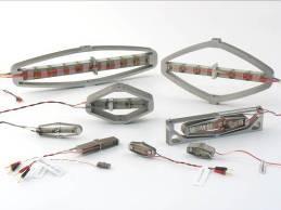
5 Since 1990, CEDRAT TECHNOLOGIES SA has developed a wide range of piezoelectric actuators. They are divided in three categories: Multilayer actuators, which are not mechanically pre-stressed, Parallel pre-stressed actuators (PPA), which are mechanically pre-stressed multilayer actuators and offer mechanical interfaces, Amplified piezo actuators (APA ), which are using the elastic properties of a metallic shell to both pre-stress the piezoelectric ceramic and amplify the displacement. Piezoelectric actuators performances are given for standard products at 20 C with maximum 60% humidity and without loading. Theses performances may change with the following parameters: Loading (spring, mass, damper) Temperature Humidity Dynamic If you need more information, please contact actuator@cedrat-tec.com Piezoelectric Actuators must be handled carefully. Lifetime of Piezoelectric Multilayer actuators is not limited by wear. They can perform millions of cycles without loss of performance provided they are operated under suitable conditions. The following elements are reducing the actuator lifetime and may induce some performances variations: Temperature Self-Heating Humidity Dynamic Environments (Shocks, Vibrations, ) Power supply and control o Electrical connections o Continuous Voltage o Over Voltages o Nature of the power amplifier o Nature of the driving signal Radiations Chemical and abrasive environment Paschen effect Mounting procedure & Integration Biases Combined effects More details on each phenomenon are given here after.
6 Performances in technical datasheet of Cedrat technologies actuators are given for a temperature between 15 C and 25 C. Typical operational temperature range is from -40 C to 80 C. For maximum lifetime, operating voltage should be minimized, especially when actuators are used with constant voltage. Actuator height is varying because of thermal expansion. The actuator height is given in laboratory conditions of temperature (20 C). An important self heating of the piezo ceramic may occur during a long use in dynamic (high frequency) operation. This can lead to depolarization or electrical breakdown of the piezo ceramic. If you have some doubts on your operating conditions please contact actuator@cedrat-tec.com for more information before starting the device. Performances in technical datasheet of Cedrat technologies actuators are given for a humidity rate of max 60% with non condensed water. Driving ceramic with a DC voltage above 60% of relative humidity is technically possible but it leads to a reduced life time. Standard actuator can perform more than 1000h supplied at their maximum voltage in a 60% humidity level. The piezo component fails under humidity mainly if it is driven with a DC voltage (ie a constant electric field). Some water is absorbed by the ceramic and generates a migration of metallic ions form the internal
7 electrodes. This migration leads to a progressive loss of isolation between these electrodes. The power consumption increases up to electric breakdown. Please do not supply the ceramic with a DC voltage above 60% of relative humidity without Cedrat technologies agreement. In this particular case the data monitoring is very important to activate the warranty especially on the following data: Hygrometry Voltage If needed an analysis should be performed by Cedrat technologies on a specific design. Most common solution is encapsulation. Then please contact actuator@cedrat-tec.com The dynamic behaviour is meet when inertial forces (acceleration of masses) are not negligible (> 10%) compared to the actuator blocked force. It is complex and requires some precautions. In harmonic case, an actuator is working in dynamic conditions if the applied frequency is higher than one third of the natural resonance frequency in the same conditions (loading and boundary conditions). Many Cedrat Technologies standard actuators are designed to withstand their full static stroke below and at the resonance. Approaching the resonance frequency the displacement will be amplified. Then the driving voltage has to be decreased to not exceed the maximum stroke. Cedrat technologies could deliver actuators with displacement sensors and a closed loop to drive the actuator at a given stroke. That solves the issue. In this particular case the data monitoring is very important to activate the warranty especially on the following data: Stroke Voltage o Frequency o Amplitude o Signal Shape If you have some doubts on your operating conditions please contact actuator@cedrat-tec.com for more information before starting the device.
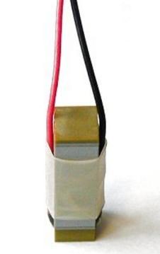
8 Shocks and Vibrations are very dependant of the operating conditions (loading and boundary conditions). If the actuator must withstand shocks or vibrations an analysis has to be performed by Cedrat technologies. If needed, please contact before doing the tests. Since piezoelectric actuators behave also as pyroelectric materials, voltage can appear, even without any power supply, due to temperature changes. The red wire corresponds to the positive electrode; the black wire corresponds to the negative electrode, which must be connected to the electrical ground. For some actuator series, the longest wire corresponds to the positive electrode. CAUTION: It is recalled that the actuator must be excited between 20 V and 150 V. A higher voltage will damage the actuator. The Strain Gauges used by CEDRAT TECHNOLOGIES display an Ohmic resistance of 350 for all the actuators. For the strain gauges 350 the driving voltage (Vcc-GND) should not be higher than 10V. The reduction of the driving voltage reduces the dissipated power and the related thermal effect, but also reduces the sensitivity of the bridge. SG Option The piezoelectric actuator can be delivered with a full bridge of strain gauges (SG option). If the SG option is sold with the sensing electronic, the linkage cable will be provided as shown below to link the conditioner to the actuator.


9 Conditionner Flex. Actuator Figure 1 Strain gauges cable Circumspection of use of these cables has to be respect not to damage the flex. It is necessary to take the flex at the chock of thickness that is to say the nearest of the links when inserting it in the cable. Besides, there is no polarizing slot on the flex, if you have no signal on gauges, check that the flex is in the right side. Do not fold the flexible. Folded flex will cancel the warranty on the component Take the flex here to connect or disconnect it Figure 2-2 : Strain Gauge connections If the SG option is sold without the sensing electronic, the linkage cable will not be provided and the customer needs to perform the linkage himself. In that case the following schematics must be respected. Vcc = red R1 Out+ = Green V SG R4 Out- = Blue R2 R3 GND = black Figure 2-3 : Schematic of the Strain Gauges bridge Figure 2-4 : schematic of the flexible pcb end (FFC 4 points 1 mm) SG Option + VAC option If the vacuum option is sold in addition to the SG option with the electronic then the cable may be cut to go through the vacuum chamber electrical interface. Then please respect the following scheme.


10 Conditionner Flex. Actuator Green : IN+ White : IN- Red : VCC Black : GND Figure 5 Strain gauges cable When driving the piezo actuator, it is important not to create over voltages through improper drivers or parasitic inductances. Standard actuators have performed billions of cycles on Cedrat technologies linear amplifier, which includes management of over voltages and over currents. Standard actuators have performed billions of cycles on Cedrat technologies linear amplifier, which includes management of over voltages and over currents. If Cedrat technologies actuators are driven with other electronics the guaranty will not apply even if they have the same characteristics. Only few cycling tests have been performed with Cedrat technologies switching power amplifiers (SA75X, X=A,B,D) as they are available only since Jan 1, 2014.
11 For application of actuator warrantee with SA75X, please refer to SA75X user manual or contact In harmonic case, Standard actuators should preferably used with sine signals with the following characteristics: Max Amplitude : 85 V 0-pk Offset : + 65 V Some precautions are needed if the command signal is not a C1 function. Those functions have a Fourier Transform with high frequencies. Those frequencies could be damageable for the actuator especially if it meets the resonance frequency. Cedrat technologies developed many solutions to face those issues. If needed please contact actuator@cedrat-tec.com before starting the device. So far, components of piezo actuators are not really sensitive to any radiations. In some specific projects piezo components were qualified up to 100krad levels.cedrat technologies can not guarantee its standard actuators without qualification phase. If required, an analysis or some tests could be performed by Cedrat technologies. Please contact actuator@cedrat-tec.com for more information. Standard actuators are not designed to withstand any chemical or abrasive environments. If needed an analysis should be performed by Cedrat technologies on a specific design. Most common solution is encapsulation. Please contact actuator@cedrat-tec.com for more information. The dielectric constant of insulation materials is sensitive to pressure temperature and humidity.
12 The dielectric constant is sensitive to the pressure this effect is called Paschen effect. Standard actuators need a specific VAC option to be compatible with vacuum applications. Then Paschen effect is analyzed and the warranty will apply only if the VAC option is ordered. The mechanical integration or the induced moments under operation by the mechanism are the main sources of failure In order to obtain good results, the mechanical interfaces along the small axis must be used. The screw is dimensioned to bear the maximum blocking force of the actuator (assuming that the screw material has an elastic limit equal or higher than 800 MPa). During the mounting procedure, electrical charges can appear on the actuator, due to external applied forces, through the direct piezoelectric effect. It is therefore recommended to mount the actuator in shortcircuited conditions. Care must be taken to avoid excessive torque in the actuator s shell. Only tensile forces can be exerted along the APA's shell small axis. A pushing force higher than the blocked force may dismount the actuator. Properties Specific standard technical Unity conditions Indicative values Max. Pulling force along static effort, blocked - free (N) correspond to the the small axis blocked force It is furthermore recommended not to touch with hands or with any kind of tool, the Multilayer Actuator component (although it is insulated). The insulating polish can indeed be damaged, leading to a destroying electric arc. An additional specific care needs to be taken when tightening the screw: the screw shall not in any way touch (including under actuation) the piezo material (Figure 2-6).


 50 for M series Max.")
13 Possible collision Figure 2-6: Care to be taken about the length of the screw In order to obtain the best possible results, the mechanical interfaces provided on the PPA axis have to be used. Excessive moments must be avoided during the mounting. To avoid lateral forces, it is highly recommended to use flexural hinges as end pieces, as illustrated here: Figure 2-7: Flexural hinges must be added to PPAs if a torque or a transverse force can occur Indicative values of maximal lateral forces given hereinafter are not guaranteed. Please note that these values cannot be taken as combined forces. Acceptable dynamic forces can be lower. Properties Specific standard technical Unit Indicative values Max. twisting torque at static effort, blocked - free (N.cm) 50 for M series Max. flexural torque at static effort, blocked - free (N.cm) 40 for M series Max. pulling force along Static or dynamic effort, (N) the actuation direction blocked - free 400 N (M series)


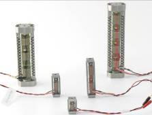
14 PPA actuators can bear a pulling force along the actuation direction axis only equal to a third of the blocked force. An excessive pulling force applied to the actuator could damage it. During the mounting procedure, electrical charges can appear on the actuator, due to external applied forces, through the direct piezoelectric effect. It is therefore recommended that the actuator be short-circuited during all assembling operations. It is furthermore recommended not to touch with hand the Multilayer Actuator component (although it is insulated). It is expressly recommended to avoid all transverse mechanical loads on the MLA. We obtain much better results by using the ceramic under mechanical pre-stress (10-30 Mpa). It is therefore advised to use a mechanical pre-stress, whenever it is possible. Without any pre-stress, the multiplayer actuator can be used neither in dynamic nor in traction. There is no applicable warranty if the MLA is use in those conditions. During the mounting procedure, electrical charges can appear on the actuator, due to external applied forces, through the direct piezoelectric effect. It is therefore recommended to mount the actuator in shortcircuited conditions. Figure 9 Multilayer actuator equiped with thermal sensors
15 The performances given in the actuator datasheet are given without loading. No combined effects are given. An analysis must be done to anticipate those effects, please contact for more information. The equipment is warranted for a period of one year from date of shipment, including parts and labor, and only under standard technical conditions as outlined above and expressly mentioned in the technical data sheet. Repairs will be carried out at Cedrat Technologies or through your vendor. During the warranty period, Cedrat Technologies will, at its option, either repair or replace products which prove to be defective. Interventions or attempts to service or repair the Actuators by any unauthorized persons will invalidate this warranty. In addition, this warranty will not apply if the actuator is subjected to any of the following: improper handling, including, but not limited to, shocks and abrasions improper installation, including, but not limited to, excessive mechanical forces and moments, failure to use the standard electrical and mechanical interfaces excessive voltage, including, but not limited to, peak values outside the recommended operating range, DC values applied for excessive time periods inappropriate environmental conditions, including, but not limited to, high temperatures or high humidity attempt to modify the standard electrical connection of the APA (soldering out of electrical wires, plugs change, ) or the standard mechanical interfaces This warranty will not apply is the proper use is not at least partially justified by the following data acquisition: Number of cycles (frequency,shape and duration) Temperature Hygrometry Depending on your application some additional data has to be recorded. Please refer to previous paragraphs to see which data is relevant to monitor to activate the warranty. No other warranty is expressed or implied. Cedrat Technologies specifically disclaims the implied warranties of merchantability and fitness for a particular purpose
16 This product has been inspected and shown to operate correctly at the time of shipment, as verified by the Factory Verification form which is delivered with the actuator. Immediately upon receipt, the product should be inspected carefully for any signs of damage that may have occurred during shipment. If any damage is found, a claim should be filed with the carrier. The package should also be inspected for completeness according to the enclosed packing list. If an order is incorrect or incomplete, contact your distributor. If a device requires service, please contact Cedrat Technologies or your local vendor. Please include the device model and serial number in all correspondence with Cedrat Technologies or your vendor. In accordance with the applicable EU law, electrical and electronic equipment may not be disposed of with unsorted municipal wastes in the member states of the EU. When disposing of your old equipment, observe the international, national and local rules and regulations. To meet the manufacturer s product responsibility with regard to this product, Cedrat Technologies (CTEC) SA ensures environmentally correct disposal of old CTEC equipment that was first put into circulation after 13 August 2005, free of charge. If you have old CTEC equipment, you can send it to the following address (please contact CTEC prior expedition): CEDRAT TECHNOLOGIES S.A. 59 Chemin du Vieux Chêne - Inovallée MEYLAN cedex - FRANCE

17
18 Blocked free resonance No-load displacement Characteristics of the SG conditioner SG gain after calibration
19 In case of trouble or breakdown with the piezo actuator, please check the electrical impedance (capacitance and insulation resistance) of the actuator and communicate it to your vendor. This form must be completed by the customer in order to: allow Cedrat Technologies to authorise the product return back to the factory, help Cedrat Technologies in repairing it. Product: Please give mention here the references and delivery date, History: Please summarize here every action which has been performed with the device since the delivery, Problem description: Please describe here the problems Please join your data acquisition of: temperature, hygrometry, number of cycle. If external forces are applied please mention it.
Demo kit by Cedrat Technologies PRODUCT AND WARRANTY INFORMATION
 Demo kit by Cedrat Technologies PRODUCT AND WARRANTY INFORMATION CAUTION: READ BEFORE OPENING For safety purposes these instructions must be read before use of this product. Piezoelectric products are
PIEZOELECTRIC OPTICAL MECHANISMS - PRODUCT AND WARRANTY INFORMATION
 PIEZOELECTRIC OPTICAL MECHANISMS - PRODUCT AND WARRANTY INFORMATION Version : 3.1.1 Date 16/03/06 CEDRAT TECHNOLOGIES URL: http://www.cedrat.com 15, Chemin de Malacher - Inovallée Email: actuator@cedrat.com
SP75 - SWITCHING AMPLIFIER FOR PIEZOELECTRIC ACTUATORS PRODUCT AND WARRANTY INFORMATION
 SP75 - SWITCHING AMPLIFIER FOR PIEZOELECTRIC ACTUATORS PRODUCT AND WARRANTY INFORMATION Version : 3.2.1 Date: 28/08/07 CEDRAT TECHNOLOGIES URL:/www.cedrat-technologies.com 59, Chemin du Vieux Chêne - Inovallée
CAU10 - MINIATURE LINEAR AMPLIFIER PRODUCT AND WARRANTY INFORMATION
 CEDRAT TECHNOLOGIES S.A. 59 Chemin du Vieux Chêne Inovallée 38246 MEYLAN CEDEX CAU10 - MINIATURE LINEAR AMPLIFIER FOR PIEZOELECTRIC ACTUATORS PRODUCT AND WARRANTY INFORMATION Version: 3.3.3 Date: 27/02/2017
LA75 - LINEAR AMPLIFIER FOR PIEZOELECTRIC ACTUATORS - CA45 COMPACT STANDALONE AMPLIFIER PRODUCT AND WARRANTY INFORMATION
 LA75 - LINEAR AMPLIFIER FOR PIEZOELECTRIC ACTUATORS - CA45 COMPACT STANDALONE AMPLIFIER PRODUCT AND WARRANTY INFORMATION Version : 3.2.3 Date: 04/11/13 CEDRAT TECHNOLOGIES SA URL: http://www.cedrat-technologies.com
Installation & Operation Manual SAGA1-K Series Industrial Radio Remote Control
 Installation & Operation Manual SAGA1-K Series Industrial Radio Remote Control Gain Electronic Co. Ltd. Table Of Contents Safety Considerations ------------------------------------------------------------2
TA MHz oscilloscope probe TA MHz oscilloscope probe
 TA375 100 MHz oscilloscope probe TA386 200 MHz oscilloscope probe User's Guide X1 X10 TA386 X1/X10 Max. 600 Vp Introduction This passive high-impedance oscilloscope probe is suitable for most oscilloscopes
PHV 1000-RO High Voltage Passive Probe. Instruction Manual
 PHV 1000-RO High Voltage Passive Probe Instruction Manual Copyright 2014 PMK GmbH All rights reserved. Information in this publication supersedes that in all previously published material. Specifications
OPERATION MANUAL FOR ALLIGATOR TUMBLE STIRRER* VP 710A
 OPERATION MANUAL FOR ALLIGATOR TUMBLE STIRRER* VP 710A *US Patent # 6,176,609 TECHNICAL NOTE 270 Figure 1. Alligator Tumble Stirrer VP 710A. WARNING!!!!! Be advised that the Magnetic Tumble Stirrer has
TETRIS 1000 High Impedance Active Probe. Instruction Manual
 TETRIS 1000 High Impedance Active Probe Instruction Manual Copyright 2015 PMK GmbH All rights reserved. Information in this publication supersedes that in all previously published material. Specifications
PHV RO High Voltage Passive Probe. Instruction Manual
 PHV 1000-3-RO High Voltage Passive Probe Instruction Manual Copyright 2012 PMK GmbH All rights reserved. Information in this publication supersedes that in all previously published material. Specifications
Models N7FS, N8FS, and N8HFS Matching networks operating guide
 Models N7FS, N8FS, and N8HFS Matching networks operating guide Wilcoxon Sensing Technologies 20511 Seneca Meadows Parkway, Germantown, MD 20876 Tel: 1-301-330-8811 Fax: 1-301-330-8873 Amphenol (Maryland)
User s Guide TX92A. Miniature Temperature Transmitters. Shop online at omega.com
 TM User s Guide Shop online at omega.com e-mail: info@omega.com For latest product manuals: www.omegamanual.info TX92A Miniature Temperature Transmitters omega.com info@omega.com U.S.A. Headquarters: Servicing
34134A AC/DC DMM Current Probe. User s Guide. Publication number April 2009
 User s Guide Publication number 34134-90001 April 2009 For Safety information, Warranties, Regulatory information, and publishing information, see the pages at the back of this book. Copyright Agilent
Model 5100F. Advanced Test Equipment Rentals ATEC (2832) OWNER S MANUAL RF POWER AMPLIFIER
 OWNER S MANUAL RF POWER AMPLIFIER") Established 1981 Advanced Test Equipment Rentals www.atecorp.com 800-404-ATEC (2832) OWNER S MANUAL Model 5100F RF POWER AMPLIFIER 0.8 2.5 GHz, 25 Watts Ophir RF 5300 Beethoven Street Los Angeles, CA 90066
Established 1981 Advanced Test Equipment Rentals www.atecorp.com 800-404-ATEC (2832) OWNER S MANUAL Model 5100F RF POWER AMPLIFIER 0.8 2.5 GHz, 25 Watts Ophir RF 5300 Beethoven Street Los Angeles, CA 90066
BROADBAND LINEAR AMPLIFIER Model P150
 ELECTRONICS AB BROADBAND LINEAR AMPLIFIER Model P150 HIGH VOLTAGE GAIN HIGH CURRENT +150V 20x 1A HIGH POWER SMALL SIGNAL SLEW RATE BANDWIDTH BANDWIDTH 30 V/µs DC to ca 60 khz DC to >200 khz FLC Electronics
ProfiScale MULTI Multimeter
 1,5 V 9V 200 mv 600 V 200 ma 1/10 A ProfiScale MULTI Multimeter en Operating instructions BURG-WÄCHTER KG Altenhofer Weg 15 58300 Wetter Germany Introduction Want the reassurance of knowing whether current
PKT 512A-RO High Impedance Passive Cable Divider
 PKT 512A-RO High Impedance Passive Cable Divider Instruction Manual Copyright 2011 PMK GmbH All rights reserved. Information in this publication supersedes that in all previously published material. Specifications
1157A 2.5 GHz Active Probe
 User s Guide A Publication number 01157-97002 September 2005 For Safety and Regulatory information, see the pages at the back of this guide. Copyright Agilent Technologies 2001-2002, 2005 All Rights Reserved.
1156A 1.5 GHz Active Probe
 User s Guide A Publication number 01156-97002 September 2005 For Safety and Regulatory information, see the pages at the back of this guide. Copyright Agilent Technologies 2001-2002, 2005 All Rights Reserved.
EchoSonic II Ultrasonic Level Transmitter LU23, LU28 & LU29 Series Quick Start NEMA 4X Enclosure
 EchoSonic II Ultrasonic Level Transmitter LU23, LU28 & LU29 Series Quick Start NEMA 4X Enclosure QS300480 Rev B 2013 Flowline, Inc. All Rights Reserved Made in USA 10500 Humbolt Street, Los Alamitos, CA
Radio Remote Controls Manual K Series
 Radio Remote Controls Manual K Series PN 52764 2010.12.20 Rev. 2 K Series radio control manual 1 Conductix Incorporated The technical data and images which appear in this manual are for informational purposes
TETRIS User's Guide. High Impedance Active Probe DO177-1
 TETRIS 1500 High Impedance Active Probe User's Guide DO177-1 TETRIS 1500 Copyright 2010 Ltd. All rights reserved. Information in this publication supersedes that in all previously published material. Specifications
Wilcoxon Research PA8HF power amplifier Operating guide
 Wilcoxon Research PA8HF power amplifier Operating guide Meggitt Sensing Systems 20511 Seneca Meadows Parkway, Germantown MD 20876, USA Meggitt (Maryland), Inc d/b/a Meggitt Sensing Systems 97012 Rev C.1
Power Resistors Cooled by Auxiliary Heatsink (Not Supplied) Thick Film Technology
 Thick Film Technology") Power Resistors Cooled by Auxiliary Heatsink (Not Supplied) Thick Film Technology FEATURES Cold system without external radiation High power / volume ratio Non-inductive Screw-on or fast-on outputs DESIGN
Power Resistors Cooled by Auxiliary Heatsink (Not Supplied) Thick Film Technology FEATURES Cold system without external radiation High power / volume ratio Non-inductive Screw-on or fast-on outputs DESIGN
Type Poles Contact configuration Rated voltage Model G7S-4A2B 24 VDC 3PST-NO, 3PST-NC
 Relays with Forcibly Guided Contacts G7S CSM_G7S_DS_E_5_ Relays Conforming to EN Standard Relays with forcibly guided contacts (EN50205 Class A, certified by VDE). Supports the CE marking of machinery
PA8HF power amplifier Operating guide
 PA8HF power amplifier Operating guide Wilcoxon Sensing Technologies 8435 Progress Drive, Frederick, MD 21701, USA Amphenol (Maryland), Inc d/b/a Wilcoxon Sensing Technologies Tel: +1 (301) 330-8811 Tel:
Model 9305 Fast Preamplifier Operating and Service Manual
 Model 9305 Fast Preamplifier Operating and Service Manual This manual applies to instruments marked Rev 03" on rear panel. Printed in U.S.A. ORTEC Part No.605540 1202 Manual Revision B Advanced Measurement
G70R-SOC08 CSM_G70R-SOC08_DS_E_2_1
 Relay Terminal CSM DS_E 1 Space-saving and Labor-saving 8-point Output Block Relay terminal is just 136 80 55 mm (W H D, when mounted upright). Independent contacts and short bar allow easy common connections.
AC/DC Current Oscilloscope Probe Model SL261
 AC/DC Current Oscilloscope Probe Model SL261 USER MANUAL I ZERO 100 mv/a 10 mv/a OFF Statement of Compliance Chauvin Arnoux, Inc. d.b.a. AEMC Instruments certifies that this instrument has been calibrated
Type Poles Contact configuration Rated voltage Model 3PST-NO, 3PST-NC 24 VDC
 Relays with Forcibly Guided Contacts G7S-@-E CSM_G7S-_-E_DS_E_3_ Lineup Now Includes -A Models Relays with forcibly guided contacts (EN525 Class A, certified by VDE). Supports the CE marking of machinery
G7K. Latching Relay. Compact Mechanical Lock Latching Relays with Manual Buttons. Model Number Structure. Ordering Information
 Latching Relay CSM DS_E Compact Mechanical Lock Latching Relays with Manual Buttons Compact design with a height of 7 mm, width of. mm, and depth of 8. mm. Plus, one Relay only weighs 7 g. Quick set and
Rev /13 SSRMAN-1B SERIES USERS MANUAL SSR INTELLIGENT BURST FIRING CONTROL COPYRIGHT 2013 NUWAVE TECHNOLOGIES, INC.
 Rev.2.2 12/13 MAN-1B SERIES USERS MANUAL INTELLIGENT BURST FIRING CONTROL COPYRIGHT 2013 MAN-1B Users Manual Page 2 TABLE OF CONTENTS 1. Ordering Codes... 2 2. Description... 2 2.1 Features... 3 3. Installation
CSM_G7S-_-E_DS_E_7_1
 Relays with Forcibly Guided Contacts G7S-@-E CSM_G7S-_-E_DS_E_7_ Relays with Forcibly Guided Contacts and High Switching Capacity of A Relays with forcibly guided contacts (EN525 Class A, certified by
APPLICATION NOTE POSITION CONTROL OF PIEZO ACTUATORS
 APPLICATION NOTE POSITION CONTROL OF PIEZO ACTUATORS INTRODUCTION The aim of this note is to help a piezo actuator user to control its system using Cedrat Technologies drivers, sensors and controllers.
VFSC9 ELECTRONIC SPEED CONTROLLER. Mounting and operating instructions
 ELECTRONIC SPEED CONTROLLER Mounting and operating instructions Table of contents SAFETY AND PRECAUTIONS 3 PRODUCT DESCRIPTION 4 ARTICLE CODES 4 INTENDED AREA OF USE 4 TECHNICAL DATA 4 STANDARDS 5 WIRING
Grid Radar Installation Manual
 Grid Radar Installation Manual MODELS GN-RD-001 120V Single Phase / Wye, 240V Single Phase, with Neutral GN-RD-002 277V 3-Phase Wye, with Neutral GN-RD-003 480V 3-Phase Delta, no Neutral GN-RD-004 208V
AP Amplifier Series RA2000 Series Amplifier Units 1WMPD
 AP Amplifier Series RA2000 Series Amplifier Units 1WMPD4003505 AP Amplifier Series RA2000 Series Amplifier Units Instruction Manual INTRODUCTION Thank you very much for purchasing the Amplifier Units,
Metallized Polypropylene Film Capacitor AC Filtering Radial Type
 Metallized Polypropylene Film Capacitor AC Filtering Radial Type FEATURES High peak current capabilities Long lifetime Material categorization: for definitions of compliance please see www.vishay.com/doc?999
Phase-sequence Phase-loss Relay
 Phase-sequence Phase-loss Relay K8AB-PH Three-phase Phase-sequence Phase-loss Relay Using Voltage Detection Method Prevents reverse motor rotation due to incorrect wiring. Distinguishes between positive
USER MANUAL. Maxwell Technologies Ultracapacitor Energy Storage Modules. Models: BMOD0058 E016 B02 BMOD0006 E160 B02. Document
 USER MANUAL Maxwell Technologies Ultracapacitor Energy Storage Modules Models: BMOD0058 E016 B02 BMOD0006 E160 B02 Document 3000200.1 Notice: The products described herein are covered by one or more of
Model 140 Inline Amplifier
 Model 140 Inline Amplifier Low Noise Inline Amplifier Small Rugged Package Includes Auto-Zero Function The Model 140 is a remote in-line DC amplifier designed to be used with bridgetype mv output transducers.
DM-46 Instruction Manual
 Auto Meter Products Inc. Test Equipment DM-46 Instruction Manual Automotive Multimeter and Inductive Amp Probe The DM-46 is the auto industry s answer to pocket portability in a 20 2650-1552-00 3/8/11
Models Z7, Z11, Z602WA and Z820WA Impedance head operating guide
 Models Z7, Z11, Z602WA and Z820WA Impedance head operating guide Wilcoxon Sensing Technologies 8435 Progress Drive, Frederick, MD 21701, USA Amphenol (Maryland), Inc d/b/a Wilcoxon Sensing Technologies
Reference only P.1 /14
 DATA SHEET Reference only P.1 /14 Part Number: PKGS-00LDP1-R 1. Scope This data sheet is applied to surface mountable acceleration sensor. 2. Part Number Murata Part Number :PKGS-00LDP1-R 3. Outline Drawing
Instruction Manual Inductive Gauging Sensor
 Instruction Manual Inductive Gauging Sensor EX-200 Series 96M0367 CONTENTS Page Part names and functions...3 Connections/Hints on correct use... 4 Installations... 5 Adjustment... 6 Specifications... 7
User s Guide TX94A. Ultra-Miniature Temperature Transmitters. Shop online at omega.com
 TM User s Guide Shop online at omega.com e-mail: info@omega.com For latest product manuals: www.omegamanual.info TX94A Ultra-Miniature Temperature Transmitters omega.com info@omega.com U.S.A. Headquarters:
INSTALLATION GUIDE. Video Balun Transceiver with fixed BNC for twisted pair operation with other balun transceivers or active receivers.
 INSTALLATION GUIDE VB37M Video Balun Transceiver for Twisted Pair Description Video Balun Transceiver with fixed BNC for twisted pair operation with other balun transceivers or active receivers. The VB37M
BC145 SIGNAL ISOLATOR BOARD
 BC145 SIGNAL ISOLATOR BOARD 4/17 Installation & Operating Manual MN1373 Any trademarks used in this manual are the property of their respective owners. Important: Be sure to check www.baldor.com to download
Operating Manual. Differential Pressure Transmitter DPS 100
 Operating Manual Differential Pressure Transmitter DPS 100 Important notes: Please read this operating manual carefully before installing and starting up the pressure transmitter. This operating manual
1. INTRODUCTION. Keywords: Piezo, Mechanism, Tip-tilt, Stability, Strain gages. BSM Mechanism context
 ATLID Beam Steering Mechanism and derived new piezoelectric based devices for optical applications F. Bourgain (1), F. Barillot (1),C. Belly (1), F. Claeyssen (1) Cedrat Technologies S.A., MEYLAN, FRANCE,
Fast Tip/Tilt Platform
 Fast Tip/Tilt Platform Short Settling Time and High Dynamic Linearity S-331 Tip/tilt angle up to 5 mrad, optical deflection angle up to 10 mrad (0.57 ) Parallel-kinematic design for identically high performance
Handling Precaution for Terminal and Connector
 1 Handling Precaution for Terminal and Connector Handling Precaution for Terminal and Connector This manual is to describe basic precautions for use of terminal and connector in the following. Make use
DCM20 Series. Three-Function DC Power Meters. DCM20 DISPLAY PRODUCT OVERVIEW FEATURES
 www.murata-ps.com DCM0 Series FEATURES Displays DC volts, amperes, watts and kilowatts. Two display modes: continuous auto cycling or fixed. 9-7 VDC voltage operation. 0.5-7 VDC voltage measurement range.
2015 RIGOL TECHNOLOGIES, INC.
 Service Guide DG000 Series Dual-channel Function/Arbitrary Waveform Generator Oct. 205 TECHNOLOGIES, INC. Guaranty and Declaration Copyright 203 TECHNOLOGIES, INC. All Rights Reserved. Trademark Information
PDu150CL Ultra low Noise 150V Piezo Driver with Strain Gauge Feedback
 PDu15CL Ultra low Noise 15V Piezo Driver with Strain auge Feedback The PDu15CL combines a miniature high voltage power supply, precision strain conditioning circuit, feedback controller, and ultra low
Registered trademarks DIGITAL COMMAND SYSTEM FOR PYROTECHNICS & SPECIAL EFFECTS. INSTRUCTIONS
 Registered trademarks DIGITAL COMMAND SYSTEM FOR PYROTECHNICS & SPECIAL EFFECTS. INSTRUCTIONS 5 and 7 / ARTS France Tel +(33) (0)1 60 65 27 27. Fax +(33) (0)1 60 65 66 22 BP N 30068 / 77983 ST. FARGEAU.
This section is specifically about safety matters
 6 4 ) 5 1 5 6 4 1 -, 1 8-4 6-4 1 5 6 4 7 + 6 1 ) 7 ) 5 2 - -,, - 6 - + 6 4. 4. 2 J E? A Thank you for choosing this Mitsubishi transistorized Inverter option. This instruction manual gives handling information
PRECISION CURRENT TRANSDUCERS. DC Current Transducers CT-100 CT-150. User s Manual. All Rights Reserved CAEN ELS d.o.o. Rev. 1.
 < DC Current Transducers CT-100 CT-150 User s Manual PRECISION CURRENT TRANSDUCERS All Rights Reserved CAEN ELS d.o.o. Rev. 1.1 November 2014 CAEN ELS d.o.o. Kraška ulica, 2 6210 Sežana Slovenija Mail:
SCREENING EFFICIENCY TESTER Model 271
 SCREENING EFFICIENCY TESTER Model 271 Operating Manual 11/1/05 1 1.0 INTRODUCTION Conductive suits are worn by power company personnel for protection while performing maintenance on live wire transmission
OPVibr Ultrasonic vibration measurement system Ultrasonic vibrometer INSTRUCTION MANUAL
 Przedsiębiorstwo Badawczo-Produkcyjne OPTEL Sp. z o.o. ul. Morelowskiego 30 PL-52-429 Wrocław tel.: +48 (071) 329 68 54 fax.: +48 (071) 329 68 52 e-mail: optel@optel.pl http://www.optel.pl Wrocław, 2015.11.04
Semi-Passive Vibration Control Technique via Shunting of Amplified Piezoelectric Actuators
 P 41 Semi-Passive Vibration Control Technique via Shunting of Amplified Piezoelectric Actuators G. Mikułowski, Institute of Fundamental Technological Research, Warsaw, Poland M. Fournier, T. Porchez, C.
CD770 DIGITAL MULTIMETER INSTRUCTION MANUAL
 CD770 DIGITAL MULTIMETER INSTRUCTION MANUAL Table of Contents 1 SAFETY PRECAUTIONS Before use, read the following safety precautions.- 1-1 Explanation of Warning Symbols 001 1-2 Warning Messages for Safe
E8EB-N0C2B E8EB-N0B2B
 Slim Sensor Ideal for Workpiece Position and Original Checking The to 1 kpa model can be used for workpiece position checking. The to 1MPa model is ideal for original pressure checking. Degree of protection
Model DB Disc Caliper Brake AIR CHAMP PRODUCTS. User Manual. (i) MTY (81)
 MTY (81)") DIST. AUTORIZADO MEX (55) 53 63 3 3 QRO (44) 95 7 60 MTY (8) 83 54 0 8 AIR CHAMP PRODUCTS User Manual Model DB Disc Caliper Brake (i) FORM NO. L-00-G-030 MEX (55) 53 63 3 3 MTY (8) 83 54 0 8 DIST. AUTORIZADO
DIST. AUTORIZADO MEX (55) 53 63 3 3 QRO (44) 95 7 60 MTY (8) 83 54 0 8 AIR CHAMP PRODUCTS User Manual Model DB Disc Caliper Brake (i) FORM NO. L-00-G-030 MEX (55) 53 63 3 3 MTY (8) 83 54 0 8 DIST. AUTORIZADO
OPERATION & SERVICE MANUAL FOR FC 110 AC POWER SOURCE
 OPERATION & SERVICE MANUAL FOR FC 100 SERIES AC POWER SOURCE FC 110 AC POWER SOURCE VERSION 1.3, April 2001. copyright reserved. DWG No. FC00001 TABLE OF CONTENTS CHAPTER 1 INTRODUCTION... 1 1.1 GENERAL...
DT1100 xx xx xx PS. Isolators, Isolator / Power Supplies. Operating Instructions
 Isolators, Isolator / Power Supplies Operating Instructions EN Contents 1. About this document...4 1.1. Function... 4 1.2. Target group... 4 1.3. Symbolism used... 4 2. For your safety...5 2.1. Authorized
AC-TX Volt/100 Volt Transformer Panel for VR61 and VR62 Loudspeakers and the CLA37 Column Loudspeaker AC-TX128
 70 Volt/100 Volt Transformer Panel for VR61 and VR62 Loudspeakers and the CLA37 Column Loudspeaker 70 Volt/100 Volt Transformer Panel for VR21 and VR51 Loudspeakers INSTRUCTION MANUAL 1. SAFETY INSTRUCTIONS
OPERATING INSTRUCTIONS
 OPERATING INSTRUCTIONS MEMFLO MFT2 2-WIRE FLOW TRANSMITTER (877) 356-5463 (p) 330-331-7331 (f) 330-331-7172 www.flo-corp.com 2017 FLO-CORP REVA 1116 1 DESCRIPTION Please read carefully! No liability can
Accelerometer Sensors
 Accelerometer Sensors Presented by: Mohammad Zand Seyed Mohammad Javad Moghimi K.N.T. University of Technology Outline: Accelerometer Introduction Background Device market Types Theory Capacitive sensor
Ordering Information. Stepping Relay Unit G9B. Model Number Legend
 Stepping Relay Unit CSM DS_E_4_1 Ideal for Controlling Pumps and Production Lines with Six or Twelve Stepping Circuits Built-in relays switch 2 A at 250 VAC or 30 VDC. Initialization of stepping with reset
ARBE-III Instruction Manual
 ARBE-III Instruction Manual Introduction ARBE-III is a solid state, fully regulated, universal power supply designed specifically for use of pre 1930 s battery operated radios. Three electronically isolated
DT1100 E xx xx (PS) Galvanic Isolators. Operating Instructions
 Galvanic Isolators. Operating Instructions") DT1100 E xx xx (PS) Galvanic Isolators Operating Instructions Contents 1. About this document...4 1.1. Function... 4 1.2. Target group... 4 1.3. Symbolism used... 4 2. For your safety...5 2.1. Authorized
DT1100 E xx xx (PS) Galvanic Isolators Operating Instructions Contents 1. About this document...4 1.1. Function... 4 1.2. Target group... 4 1.3. Symbolism used... 4 2. For your safety...5 2.1. Authorized
User s Guide. Model MA A AC Mini Clamp-on Meter
 User s Guide Model MA150 200A AC Mini Clamp-on Meter Introduction Congratulations on your purchase of Extech s MA150 AC Mini Clamp Meter. This meter is shipped fully tested and calibrated and, with proper
INSTALLATION AND MAINTENANCE MANUAL FOR GROUND MONITOR GM-250 COPYRIGHT 1983 AMERICAN MINE RESEARCH, INC.
 INSTALLATION AND MAINTENANCE MANUAL FOR GROUND MONITOR GM-250 COPYRIGHT 1983 AMERICAN MINE RESEARCH, INC. MANUAL PART NUMBER 180-0036 ORIGINAL: 1-17-83 REVISION: B (8-26-86) NOT TO BE CHANGED WITHOUT MSHA
POWER AMPLIFIER. Owner s Manual Mode d emploi Bedienungsanleitung Manual de instrucciónes CLIP SIGNAL TEMP PROTECTION POWER
 POWER AMPLIFIER Owner s Manual Mode d emploi Bedienungsanleitung Manual de instrucciónes TEMP PROTECTION POWER A CLIP SIGNAL B ON OFF M Introduction Thank you for purchasing a Yamaha C450/320/160 series
Agilent N2780A, N2781A, N2782A, and N2783A Current Probes
 Agilent N2780A, N2781A, N2782A, and N2783A Current Probes User s and Service Guide Agilent Technologies Notices Agilent Technologies, Inc. 2007 No part of this manual may be reproduced in any form or by
AC 24, 110, 120, 230, 240 DC 6, 12, 24, 48 LED indicator with test button G2R-1-SNI (S) G2R-2-SNI (S) Diode
 G2R-2-SNI (S) Diode") General-purpose Relay CSM_G2R-_-S_(S)_DS_E 3 Slim and Space-saving Power Plug-in Relay Reduces wiring work by 60% when combined with the P2RF-@-PU Push-In Plus Socket (according to actual OMRON measurements).
General-purpose Relay CSM_G2R-_-S_(S)_DS_E 3 Slim and Space-saving Power Plug-in Relay Reduces wiring work by 60% when combined with the P2RF-@-PU Push-In Plus Socket (according to actual OMRON measurements).
User s Guide RIGOL. PA1000 Series Power Amplifier. Publication number: UGF Mar RIGOL TECHNOLOGIES, INC. All Rights Reserved.
 User s Guide Publication number: UGF01103-1110 Mar. 2017 PA1000 Series Power Amplifier 2009 TECHNOLOGIES, INC. All Rights Reserved. Copyright Information 2009 TECHNOLOGIES, INC. All Rights Reserved. products
Applications. Overview. Benefits. Ordering Information. Pulse Transformers Device for HD-PLC, PLT Series
 Pulse Transformers Device for HD-PLC, PLT Series Overview The KEMET PLT pulse transformers are common mode choke coils suitable for Power Line Communication (PLC). Designed with our proprietary ferrite
731A seismic accelerometer and P31 power unit/amplifier Operating guide
 731A seismic accelerometer and P31 power unit/amplifier Operating guide Caution: This manual should be read carefully before installation. Wilcoxon Sensing Technologies 8435 Progress Drive, Frederick,
Operating Manual. Model 832 & 832M1 Accelerometer
 Model 832 & 832M1 Accelerometer Measurement Specialties, Inc. Vibration Sensors Design Center 32 Journey, Suite 150 Aliso Viejo, CA 92656 USA Tel: 949-716-7324 www.meas-spec.com vibration@meas-spec.com
MODEL 5002 PHASE VERIFICATION BRIDGE SET
 CLARKE-HESS COMMUNICATION RESEARCH CORPORATION clarke-hess.com MODEL 5002 PHASE VERIFICATION BRIDGE SET TABLE OF CONTENTS WARRANTY i I BASIC ASSEMBLIES I-1 1-1 INTRODUCTION I-1 1-2 BASIC ASSEMBLY AND SPECIFICATIONS
INSTRUCTION MANUAL FOR EIDS/S POWER SUPPLY
 INSTRUCTION MANUAL FOR EIDS/S POWER SUPPLY -0?.1'08 MODEL /0-4o- (- I) --.l- r). SERIAL NO. 9 IC ~ J..3 g L ( (201) 922-9300 ELECTRONIC MEASUREMENTS INC. 405 ESSEX ROAD, NEPTUNE, N.J. 07753 0,tJ, Ctl-f0
Model 9302 Amplifier-Discriminator Operating and Service Manual
 Model 9302 Amplifier-Discriminator Operating and Service Manual Printed in U.S.A. ORTEC Part No. 733690 1202 Manual Revision C Advanced Measurement Technology, Inc. a/k/a/ ORTEC, a subsidiary of AMETEK,
9 PIECE TUNGSTEN CARBIDE HOLE SAW KIT. Model 90721
 9 PIECE TUNGSTEN CARBIDE HOLE SAW KIT Model 90721 Set up And Operating Instructions Diagrams within this manual may not be drawn proportionally. Due to continuing improvements, actual product may differ
TBX-1329 AC/DC COUPLING TERMINAL BLOCK
 INSTALLATION GUIDE TBX-1329 AC/DC COUPLING TERMINAL BLOCK Introduction This guide describes how to install and use the TBX-1329 AC/DC coupling terminal block with the SCXI-1120, SCXI-1120D, and SCXI-1121
PARALLEL MULTI-AMP KIT for 7200 Series AMPLIFIERS INSTRUCTION SHEET
 2 5 0 7 W a r r e n S t r e e t, E l k h a r t, I N 4 6 5 1 6 U S A 5 7 4. 2 9 5. 9 4 9 5 w w w. A E T e c h r o n. c o m PARALLEL MULTI-AMP KIT for 7200 Series AMPLIFIERS INSTRUCTION SHEET Kit Contents:
Proximity Sensor Terminology
 The following descriptions refer to the European standard EN 60947-5-2. of 2007. The specifications given here are intended to be minimum performance values described by the standard. Alignment must not
The table below lists the symbols used on the Clamp and/or in this manual. Important Information. See manual.
 i310s AC/DC Current Clamp Instruction Sheet Introduction The i310s Current Clamp ( Clamp ) has been designed for use with oscilloscopes and digital multimeters for accurate nonintrusive measurement of
QL55 Series Luminescence Sensor
 Self-contained, microprocessor-based luminescence sensor Features Self-contained design in a robust, compact metal housing High sensitivity Microprocessor-controlled Senses luminescent marks, even on luminescent
SI-125 Power Amplifier Manual 6205 Kestrel Road; Mississauga, Ontario; Canada; L5T 2A1 November 2016, Rev 0.5
 SI-125 Power Amplifier Manual 6205 Kestrel Road; Mississauga, Ontario; Canada; L5T 2A1 November 2016, Rev 0.5 Phone: (905) 564-0801 Fax: (905) 564-0806 www.telecor.com E:\T2-108\T2-M108-ABC\T2-M108-B.doc/AD
Operating Instructions
 Operating Instructions Torque Transducer Type CD9515 Series Please read instruction carefully. Important Advice: The torque transducers of type CD9515 are suitable for applications in laboratories (for
P-810 P-830 Piezo Actuators
 P-810 P-830 Piezo Actuators For Light and Medium Loads The newest release for data sheets is available for download at www.pi.ws. Cat120E Inspirations2009 08/10.18 1-70 P-810 piezo actuators Outstanding
Installation and Operational Instructions for ROBA -switch Type 017._00.2
 OBA -switch Type 017._00.2 Guidelines on the Declaration of Conformity A conformity evaluation has been carried out for the product in terms of the EC Low Voltage Directive 2014/35/ EC and the EMC Directive
Signal Isolation Module. Instruction Manual SIM
 Signal Isolation Module Instruction Manual SIM200-000 Table of Contents 1. General Description... 3 2. Specifications... 3 2.1 Electrical... 3 2.2 Physical... 4 3. Installation... 4 3.1 Wiring Guidelines...
DUAL OUTPUT AC CURRENT/VOLTAGE TRANSDUCER
 OPERATOR S MANUAL DUAL OUTPUT AC CURRENT/VOLTAGE TRANSDUCER Masibus Automation & Instrumentation Pvt. Ltd. B/30, GIDC Electronics Estate, Sector-25, Gandhinagar-382044, Gujarat, India Web Site: www..com
XPR522 XPR540. XPR SERIES INSTALLATION / OWNER'S MANUAL Mobile Power Amplifiers
 XPR522 XPR540 XPR SERIES INSTALLATION / OWNER'S MANUAL Mobile Power Amplifiers Preparation Please read entire manual before installation. Due to the technical nature of amplifiers, it is highly recommended
USER S MANUAL POWER SUPPLY - ISOLATOR - SIGNAL CONVERTER ZSP 41 POWER SUPPLY - ISOLATOR - SIGNAL CONVERTER SIGNAL MULTIPLIER ZSP 41/2
 (ENG) DECEMBER 2017 USER S MANUAL POWER SUPPLY - ISOLATOR - SIGNAL CONVERTER ZSP 41 POWER SUPPLY - ISOLATOR - SIGNAL CONVERTER SIGNAL MULTIPLIER ZSP 41/2 ISOLATOR - SIGNAL CONVERTER TYPE SP 11 CURRENT
EchoSonic II Ultrasonic Level Transmitter LU27 Series Quick Start NEMA 4X Enclosure
 EchoSonic II Ultrasonic Level Transmitter LU27 Series Quick Start NEMA 4X Enclosure QS300116 Rev C 2013 Flowline, Inc. All Rights Reserved Made in USA 10500 Humbolt Street, Los Alamitos, CA 90720 USA Tel: