OPERATION INSTRUCTIONS
|
|
|
- Egbert Park
- 6 years ago
- Views:
Transcription


1 Tel: Fax POWER TIG 210EXT DIGITAL TIG WELDER OPERATION INSTRUCTIONS Version
2 2
3 3 Thank you for selecting the R-Tech POWER TIG 210EXT Digital Inverter AC/DC Tig Welder. The POWER TIG 210EXT Digital has many benefits over traditional TIG welders, including 9 memory stores, advanced AC waveforms, pulse welding, slope up/down, remote foot option and an industrial 60% duty cycle. We want you to take pride in operating our POWER TIG 210EXT Digital as much pride as we have taken in making this product for you. Please read all information in this manual before operation PLEASE EXAMINE CARTON AND EQUIPMENT FOR DAMAGE IMMEDIATELY When this equipment is shipped, title passes to the purchaser upon receipt from the courier. Consequently all claims for material damaged in shipment must be made by purchaser against the transportation company used. Please record your equipment identification below for future reference. This information can be found on data plate at rear of machine. Product POWER TIG 210EXT DIGITAL Serial No. Date of Purchase Where Purchased Whenever you request replacement parts or information on this equipment please always supply information you have recorded above This product is covered by our 2 year collect and return UK warranty, External items, torch, earth lead etc are covered by 3 months warranty. Any faults/damage found caused by customer will be charged pro-rata. Pay particular attention to the safety instructions we have provided you for your protection The level of seriousness to be applied to each section is explained below WARNING This statement appears where the information must be followed exactly to avoid serious personal injury. CAUTION This statement appears where the information must be following to avoid a minor personal injury or damage to this equipment.
4 4 Introduction The R-Tech POWER TIG 210EXT Digital is a member of our field acclaimed family of welding products. Premium features include:- 1. Inverter power source more efficient to operate, provides smoother weld characteristics. 2. Full Featured Pulse welding in AC & DC Tig welding modes 3. HF Arc start Easy arc striking and prolonged tungsten life 4. Slope up / slope down 5. Remote foot pedal option 6. Digital control panel with 9 memory store function. 7. Industrial 60% Duty cycle at C 8. Easy setup mode for automatic setting of parameters. Recommended Processes The R-Tech POWER TIG 210EXT Digital is recommended for the Tig welding processes within its output capacity of 210 Amps Equipment Limitations The R-Tech POWER TIG 210EXT Digital is protected from overloads beyond the output ratings and duty cycle as per machine specifications with thermostat protection of the output coils and rectifiers. Welding Capability Duty Cycle The R-Tech POWER TIG 210EXT Digital is rated at 210 Amps at 60% duty cycle on a ten minute basis. If the duty cycle is exceeded a thermal protector will shut machine off until the machine cools. Technical Specifications Model No. POWER TIG 210EXT DIGITAL Input 240V AC 50/60Hz PFC Input Amperage TIG 16A MMA 23A MMA No-load Voltage 70v Current Range 20A 160A Rated Output Current 35%, 100% Arc Force Control 0-100% Hot Start 0-2 seconds Hot Start Amps % 0-100% VRD Safety Function Yes TIG No-load Voltage 70v Current Range 5A 210A DC Mode, 10A - 210A AC Mode Rated Output Current 210A Duty Cycle Tig Up-Slope Time 0-25 Seconds Down-Slope Time 0-25 Seconds Pulse Frequency Range Hz DC Hz AC Advanced Squarewave Soft Square, Triangular & Sinewave Pulse Width Range 3-100%
5 5 Pulse Amperage Range 5-95% Gas Post Flow Time 0-50 Seconds Gas Pre Flow Time 0-25 Seconds Arc Starting Mode High Frequency AC Waveforms Advanced Squarewave Soft Squarewave Triangular Sine Wave AC Balance Control 5-90% of Electrode Positive AC Easy Start Parameters AC Frequency 120Hz AC Balance 25% Pre flow Gas.5 seconds Post Flow Gas 4 seconds Main Amps 120A Start/End Amps 50A Upslope 1 seconds Downslope 3 seconds DC Easy Start Parameters Pre flow Gas.5 seconds Post Flow Gas 4 seconds Main Amps 90A Start/End Amps 50A Upslope 1 seconds Downslope 3 seconds Gross Weight 24 KG Insulation IP21S Dimensions mm 438H x 232W x 550L (mm) Read entire section before starting installation Safety Precautions WARNING! Electric Shock can kill Only qualified personnel should perform this installation. Turn off input power at the fuse box before working on this equipment. Do not touch electrically live parts. Always connect the machine to an earthed mains supply as per national recommended standards. Select suitable location Place the welder where clean cooling air can freely circulate in and out of the front & rear louver vents. Dirt, dust or any foreign material that can be drawn through vents into welder must be kept to a minimum. Failure to observe these precautions can result in excessive operating temperatures which can lead to plant failure. Grinding Do not direct grinding particles towards the welder. An abundance of conductive material can cause plant failure. Stacking

6 6 This machine cannot be stacked. Transport Unloading Never underestimate the weight of equipment, never move or leave suspended in the air above people. Use recommended lifting equipment at all times. WARNING! Falling Equipment can cause injury. Never lift welder with gas bottle attached. Never lift above personnel. Tilting Machine must be placed on a secure level surface or on a recommended undercarriage/trolley. This machine may topple over if this procedure is not followed. Environmental Rating The welding power source carries the IP21S rating. It may be used in normal industrial and commercial environments. Avoid using in areas where water / rain is around. Read and follow the Electric Shock Warnings in the safety section if welding must be performed under electrically hazardous conditions such as welding in wet areas or water on the work piece. Electrical Installation WARNING! ELECTRIC SHOCK CAN KILL Machine grounding and High Frequency Interference Protection This welder must be grounded to earth. See national electrical codes fro proper grounding methods. The high frequency generator being similar to a radio transmitter may cause interference to radio, TV and other electronic equipment. These problems may be the result of radiated interference. Proper grounding methods can reduce or eliminate this. Radiated interference can develop in the following ways 1. Direct interference from welder power source 2. Direct interference from the welding leads
7 7 3. Direct interference radiated from feedback into power lines 4. Interference from re-radiation by un-grounded metallic objects. Keeping these contributing factors in mind, installing equipment as per following instructions should minimize problems. 1. Keep the welder input power lines as short as possible and enclose as much of them as possible in metal conduit or equivalent shielding. There should be a good electrical contact between this conduit and ground (Earth). 2. Keep the work and electrode leads as short as possible. Tape the leads together where practical. 3. Be sure the torch and earth leads rubber coverings are free from cuts and cracks that allow welding power leakage 4. Keep earth lead connection to work in good condition Clean area on workbench where earth clamp is situated on a regular basis. Input Connections Make sure the voltage, phase and frequency of input power is as specified on machine rating plate located at rear of machine. Have a qualified electrician provide suitable input power as per national electrical codes. Make sure machine is earthed / grounded. Make sure fuse or circuit breaker is correct rating for machine. Using fuses or circuit breakers smaller than recommended will result in nuisance shut off from welder inrush currents even if welding at low amperages. Failure to follow these instructions can cause immediate failure within the welder and void machines warranty. Turn the input power OFF at the mains switch & fuse box before working on this equipment. Have a qualified electrician install & service this equipment. Allow machine to sit for 5 minutes minimum to allow the power capacitors to discharge before working inside this equipment. Do not touch electrically live parts The POWER TIG 210EXT DIGITAL Inverter Tig Welder requires a 240V 50/60Hz supply. It requires a 16A supply for Tig operation and 23A for MMA welding. It comes with a 2.5 metre mains cable attached. Connect wires according to national coding. Brown wire Live Blue wire Neutral Green/Yellow Wire Earth (Ground)
8 8 Connecting to a mains electrical supply THIS MACHINE IS OF AN INDUSTRIAL SPECIFICATION AND MUST BE FITTED TO A MINIMUM of 23AMP 240V MAINS INPUT Connecting to an Engine Driven Generator If connecting this machine to an engine driven generator please ensure the following Minimum Generator KVA Output 7.0 KVA continuous Generator to be fitted with AVR (automatic voltage regulation) DO NOT USE ON A GENERATOR WITHOUT AVR Connecting to a generator without the above minimum requirements will invalidate your warranty.

 2.")
9 9 Connections for POWER TIG 210EXT Digital Rear machine connections 1. On/Off Switch V AC Auxiliary output Fig 1 Connect water cooler to socket, when machine is turned on by on/switch it will then output power from aux socket. Fig Main chassis earth bolt If you experience interference you can fit extra earth to this point (Not normally used) 2. Gas Input connector Connect input gas hose ensuring connection is tight - 34/8 BSP thread 3. Mains input cable Fit required plug as per your electrical installation
10 10 Connections for TIG (GTAW) Welding Fig 2 1. Negative power connector - Connect Tig Torch Dinze to power connector by inserting and twisting until tight ENSURE TIG TORCH IS FITTED TO NEGATIVE CONNECTOR OTHERWISE YOU WILL EXPERIENCE TUNGSTEN BURNBACK 2. Gas outlet - Quick release type Connect the torch gas hose 3. Positive power connector + Connect the earth lead to by inserting and twisting until tight and the earth clamp to work/bench 4. Torch control socket 7-Pin Connect torch control plug To avoid a High Frequency shock keep the Tig torch in good condition and replace if any of the insulation is damaged. Connect the gas input hose to gas regulator and use Pure Argon Gas, available from local suppliers. Set gas flow/pressure to 8-12 LPM. Make sure gas bottle is secured to avoid injury. Remote Foot Pedal connection. Disconnect Tig Torch switch plug from torch control socket (Fig2.4) and connect plug from foot pedal.

11 11 Connections for STICK MMA (SMAW) Welding 1. Negative power connector - Fig 3 Connect the earth lead to by inserting and twisting until tight and the earth clamp to work/bench. 2. Not used for MMA welding 3. Positive power connector + Connect the electrode holder by inserting and twisting until tight 4. Not used for MMA welding

12 12 Controls and Settings Fig 4 1. Memory store function There are 9 memory store programs to enable you to select required parameters for job in hand and then store to select channel. Press memory button until required program you wish to store is showing in LED Then enter parameters as required, now press and hold save button for 3 seconds and release, the green save LED will now light for about 2 seconds and then go out. The parameters have now been stored. The red select LED will then come back on, if you make any more adjustments these will not be save until you save again 2. Normal / Easy start setup This machine features two easy startup modes, one for AC and one for DC. They have preprogrammed settings that are generally useable for most situations and many parameters will be blocked out, however you can still adjust amperage etc. In normal mode ALL functions can be programmed.
13 13 3. Pre-flow gas Adjustable from 0-25 seconds, this enables the backed up gas pressure to be released from torch before actual arc is started. Common settings for most application is about.3 to.5 seconds - If welding stainless steel etc sometimes a longer pre-flow is required. 4. Start Amperage This allows you to set the initial start current from 5A DC and 10A AC. In 4T mode when trigger is pressed and held you will remain at start amps, when you let go machine will then go to main set amps. Do not set the start amperage too low for tungsten size otherwise you may experience sluggish / non arc starting. I.E A 3.2mm tungsten is for high range 160+ amps welding, so you would not need to set start amps at 5. The thicker the tungsten used the higher the start amperage has to be. We recommend to achieve faster arc starting:- 1.0mm Tungsten - 5 Amps minimum 1.6mm Tungsten Amps minimum 2.4mm Tungsten - 40 Amps minimum 3.2mm Tungsten - 60 Amps minimum Note: Start amps is used when using foot pedal as well, so ensure this is set to above guide. 5. Up-Slope Adjustable from 0-25 seconds, This allows you to gradually increase the amperage from start amps to main amps when using torch trigger operation. When using foot pedal ensure up-slope is set to 0 or you may experience sluggish arc starting. 6. Main current control This adjusts the main welding current and is shown in L.E.D (Fig 4.24) when welding is in process. Welding range AC is 10A to 210A Welding range DC is 5A to 210A 7. Pulse width adjustment (pulse on time) When pulse welding you have the main (peak) amperage and base (background) amperage set. By adjusting the width you determine which will be more prominent, the pulse or the base. This is adjustable from 5-95%. At a low % the base current will be on long so you will reduce heat input. At a high % the pulse current will be more prominent so you will get increased heat input.. 8. Pulse amps % This sets the base amperage as a % of main amps set. I.E if mains amperage is 120A and you set to 50%, base amps will be 60A You can use the remote foot pedal and as you depress the pedal and raise the main
14 14 amperage the base amperage will adjust to pulse amps %. 9. Pulse frequency adjustment This can be adjusted as follows: DC Mode 0.1 to 500Hz AC Advanced Squarewave Hz AC Soft Square, Triangular and Sinewave Hz Advanced AC Pulse Hz 10. AC Frequency Transformer based welders are normally fixed at 60Hz, due to the advanced inverter technology you can adjust from Hz. The higher the AC frequency the narrower the arc becomes allowing you to have a more precise weld bead and penetration. This can also quicken up travel speed and ideal for production welding. You will hear the pitch of the weld noise get higher, this is normal. Welding at lower frequency will give reduced control of arc and a wider weld pool. 11. AC Balance This sets the % of electrode positive used during AC welding to provide a cleaning action as alloys have a oxide layer that has a higher melting temperature than the base metal and this needs to be lifted off. So you can control the amount of cleaning or penetration. Too much cleaning will cause the tungsten to wobble and split, Too little cleaning can result in a dirty dull weld. So as you increase the % the more cleaning will happen however less penetration will be achieved. For most situations a setting of 30-40% will give you a good clean weld finish, If you go above 50% you will find the tungsten will overheat and the end can fall of into weld pool. If you find you are getting tungsten wobble using 30-40% balance then you may need to go up a tungsten size. 12. Down-Slope Adjustable from 0-25 seconds, This allows you to gradually decrease the amperage from main amps to end/final amps when using torch trigger operation. When using foot pedal ensure down-slope is set to End Amperage This allows you to set the end current from 5A DC and 10A AC. In 4T mode when trigger is pressed and held the second time you will remain at end amps, when you let go machine will then stop welding.
15 15 Note: When using foot pedal ensure this is set to minimum unless you want to have a HOT burst at end of weld. 14. Post Flow Gas Adjustable from 0-50 seconds. When you stop welding the gas will continue to flow for this set amount of time, this allows the tungsten to cool without getting contaminated and also protect the weld bead until it has cooled slightly. For up to 100 amps use about 8 seconds, for use 12 seconds and use 15 seconds. 15. Process selector Options are:- HF Tig - For automatic arc starting (normal setting for AC & DC Tig Welding) Lift Tig - If welding near sensitive electronic devices (car ECU etc) DC Only Stick - NON VRD - Normal 70v OCV is present before welding happens Stick - VRD (Voltage reduction device). The OCV is reduced to below 20V (+/- 3v) for added safety. Once the electrode touches workpiece the arc is established and weld carries on as normal. However when using VRD sometimes it can be harder to strike the arc and you may need to scratch the electrode on work a bit more, even more so with rusty / dirty metals. When welding with VRD you may notice a slight delay in the initial striking, this is normal. 16. Parameter selector Press this button to scroll left to right through the machine parameters 17. Parameter adjuster Turn this knob to adjust parameter values, if you hold the knob in and turn it increase adjustment speed. 18. MMA Arc Force control This controls the arc response to when electrode is held close/away from workpiece. Arc force automatically adjusts by changing the volts / amps to maintain a stable arc. This is represented as a % of available arc force amperage 19. MMA Hot Start time Adjusts the time from 0-2 seconds that the hot start will happen at beginning of weld. This helps to reduce electrode sticking to work. 20. MMA Hot Amps % For controlling the amount of extra amps when the arc is first started and prevents the electrode sticking to work. Adjustable from 0-100% of hot start amps available.
16 Tig Pulse mode selector This machine has two pulse modes. Standard pulse works in both AC and DC modes Advanced AC pulse works only in AC mode Pulse is used to help control the amount of heat going into workpiece and commonly used on stainless steels and alloys. It standard mode AC, both the pulse peak and base amperage are AC In standard mode DC, both the pulse and base amperage are DC In advanced AC pulse mode, the machine pulses between AC and DC- and is ideal to control the heat input on thin alloys T/4T, remote foot pedal and torch amp control selector 2/4 Step trigger mode switch Tig welding can either be done in 2 or 4 step mode. When the trigger mode is in the 2 step position the following sequence will occur Press and hold the Tig torch switch to start sequence. The machine will open gas valve to start flow of shield gas, after the set pre-flow time to purge air from torch hose the welding output of machine will be turned on and the arc will be started. After the arc is started the output current will increase from the start (min) current to base (main) current in time selected by slope-up. Release the Tig torch switch to end sequence. The machine will now decrease output to finish (min) current in time set by slope-down, once at finish (min) current the machine will stop output and the gas valve will continue to operate for the selected time (post flow) Possible variations of this standard sequence are shown in diagram below. It is possible to press and hold Tig torch switch a second time during down slope time to restart. After the switch is pressed the output current will raise to base (main) current
17 17 When the trigger mode is in the 4 step position the following sequence will occur Press and hold the Tig torch switch to start sequence. The machine will open gas valve to start flow of shield gas, after preset gas pre-flow time to flow time to purge air from torch hose the welding output of machine will be turned on and the arc will be started at start (min) current This condition can be maintained as long as required. Release the Tig torch switch to go to step 2, the machine will now increase output to peak (main) current in time set by slope-up. Press and hold the Tig torch switch when main weld is complete The machine will now decrease the welding output current to finish (min) in down-slope time set. Once at finish (min) output you can release the Tig torch switch to end weld the gas post-flow will continue to run for set time. Foot pedal operation When using a foot pedal you can adjust the amperage while you are welding by pressing the pedal, the more you press the more amps you will achieve. The foot pedal at maximum depression will go to the amperage set in LED before welding. I.E set the welding amps to 120A and when pedal is fully depressed you will achieve 120Amps. Foot pedal can't be used with 4T operation, ensure 2T operation is set. Remote amperage torch When using a remote amperage torch you can adjust the amperage while you are welding
18 18 by using your thumb to adjust knob on torch handle. This does take some getting used to but is handy when you are welding in a position where a foot pedal is not use-able. You can use a remote amperage torch in 2T or 4T mode, most common is 4T as you press trigger to start weld and then release you can then use thumb/finger for torch switch to adjust amperage knob, once weld has finished press the torch switch again to finish weld. 23. AC Waveform / DC selector The POWER-TIG210EXT features AC and DC operation, it also has 4 x AC waveforms allowing very specialised welding to be carried out. Advanced Squarewave is the default mode and offers excellent arc control. Soft square and Sinewave are similar to older transformer style welders. Soft square gives a smooth buttery feel and maintains good control of the arc Sinewave gives a softer arc with less control. Triangular wave is designed for rapid wet in and high travel speed and a rapid freeze of weld puddle. 24. LED Data indicator This single display shows the data always accompanied by a corresponding LED light which indicates what value is being represented. Amps Seconds Percent % Hertz Warning On This also includes a self diagnosing function which shows an error code if case of machine problem..


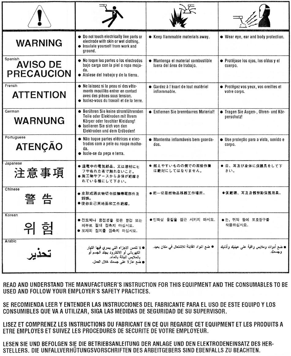
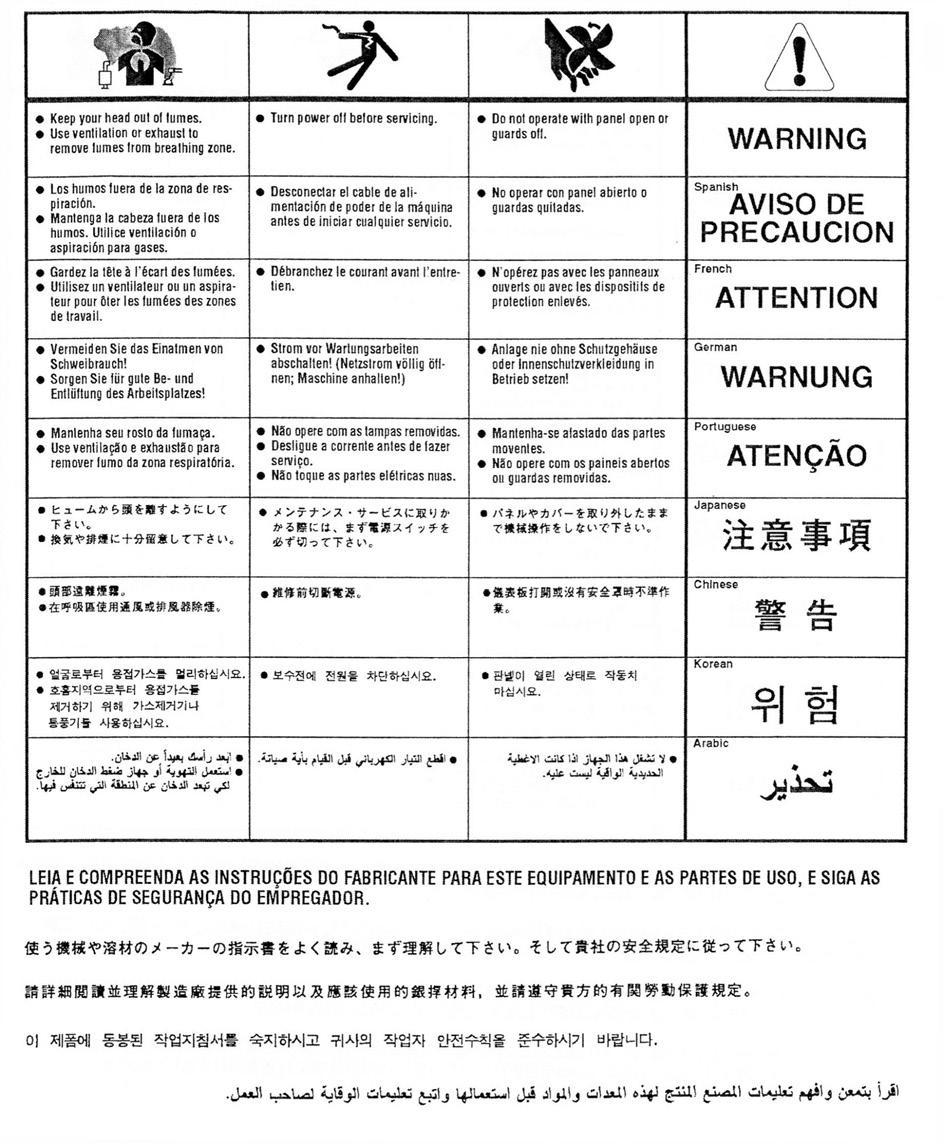
19 19 Operating machine SAFETY PRECAUTIONS WARNING! ELECTRIC SHOCK CAN KILL Do not touch electrically live parts or electrode with skin or wet clothing. Insulate yourself from work and ground Always wear dry insulating gloves WARNING! FUMES AND GASES can be dangerous Keep your head out of fumes & gases produced from welding. Use ventilation or exhaust to remove fumes & gases from breathing zone and general area. WARNING! WELDING SPARKS can cause fire or explosion Keep flammable material away from work area. Do not weld on containers that have held combustibles WARNING! ARC RAYS can burn Wear eye, ear and body protection Make sure work area is protected by proper shielding to avoid injury to passers by.
20 20 Welding in TIG mode No Pulse No remote foot pedal 1. Connect the Tig Torch to machine, connect earth lead to machine & work piece. 2. Set to Tig mode pulse off (Fig 4.21) 3. Select 2 or 4 way torch operation (Fig 4.22) 4. Connect Argon gas and set flow to approx 8-12 LPM 5. Set Gas post flow to 3 x diameter of tungsten width (Fig 4.14) 6. Adjust welding amps to desired welding current 7. Press the Tig torch switch to start welding and release to finish Welding in TIG mode with Pulse No remote foot pedal 1. Connect the Tig Torch to machine, connect earth lead to machine & work piece. 2. Set to Tig mode pulse on (Fig 4.21) 3. Select 2 or 4 way torch operation (Fig 4.22) 4. Connect Argon gas and set flow to approx 8-12 LPM 5. Set Gas post flow to 3 x diameter of tungsten width 6. Adjust Pulse freq. to desired setting (how often pulse happens) (Fig 4.9) 7. Adjust base amperage % (Fig 4.8) 8. Adjust pulse width to desired setting (how long pulse happens) (Fig 4.7) 9. Adjust main current for maximum welding current (Fig 4.6) 10. Press the Tig torch switch to start welding The benefits of pulse welding is the ability to control the weld pool and amount of heat absorbed by work resulting in a smaller heat affected zone which results in fewer deformations and reduced chance of cracking. There are no set rules for pulse welding as this is down to personal choice by the welder. Welding in TIG mode with Remote foot pedal 1. Connect the Tig Torch to machine, connect earth lead to machine & work piece. 2. Connect remote foot pedal to machine 3. Set to Tig mode pulse off or Tig mode pulse on (Fig4.21) In welding with pulse in foot pedal, the foot pedal controls peak main welding amperage 4. Select 2 way torch operation (Fig 4.22) Foot pedal will not work in 4-WAY mode 5. Connect Argon gas and set flow to approx 8-12 LPM 6. Set Gas post flow to 3 x diameter of tungsten width 7. Adjust peak current knob on machine to desired maximum welding current that foot pedal will go to. 8. Press the foot pedal to start welding. (on maximum depression it will go to maximum amps set on machine) Note: When welding with remote foot pedal Upon pressing of foot pedal welding arc will start, if you find it hard to start arc push pedal down a bit further to aid starting. The benefits of a remote foot pedal is greater control of amount of heat going into work. Press pedal fully to start weld, upon weld pool formation you can release the pedal to decrease amperage to sustain perfect weld pool and increase again as required to sustain weld characteristics. The foot pedal adjusts from Start (min) current to maximum current as set on main current knob on front of machine.
21 21 Welding in TIG mode with Remote amperage torch 1. Connect the Tig Torch to machine, connect earth lead to machine & work piece. 2. Set to Tig mode pulse off or Tig mode pulse on (Fig4.21) In welding with pulse in remote torch, the foot pedal controls peak main welding amperage 3. Select 2T or 4T torch operation (Fig 4.22) - Ensure the PEDAL (remote) led is illuminated. 4. Connect Argon gas and set flow to approx 8-12 LPM 5. Set Gas post flow to 3 x diameter of tungsten width 6. Adjust welding amps knob on machine to desired maximum welding current that remote torch will go to. 7. Press the torch switch to start welding. (on maximum it will go to maximum amps set on machine) Tig tungsten size / amperage guide All values below are based on using pure argon shielding gas. Other current values may be employed depending on the shielding gas and application ELECTRODE RATINGS Electrode Diameter (mm) 2% Thoriated on DC (amps) Red Tip Grind to point Pure Tungsten on DC (amps) Zirconiated 0.8% Tungsten on AC (amps) White Tip No need to grind 1.0mm / mm / 1/ mm/ 3/ mm / 1/ mm / 5/ mm / 3/ mm / 1/ Welding in STICK MMA (SMAW) Mode 1. Fit MMA electrode holder to + terminal on machine (Fig 3.3) 2. Fit earth lead to - terminal on machine and to work piece (Fig 3.1) 3. Select stick on front panel (Fig 4.15) 4. Place electrode in holder 5. Select desired welding current (Fig 4.24) with selector knob (Fig4.17) 6. Select desired MMA options, Arc Force, Hot start time and Amps (Fig ) 7. Strike arc and weld WARNING! ELECTRIC SHOCK CAN KILL When machine is switched to MMA mode, output terminals are always live, take care and do not touch electrode and earth by person at same time, otherwise electric shock will occur. The foot pedal has no affect on welding current in MMA mode and the gas flow and high frequency starting circuit is disabled.
22 22 Maintenance Routine and periodic maintenance WARNING! ELECTRIC SHOCK CAN KILL Turn the input power OFF at the mains switch & fuse box before working on this equipment. Have a qualified electrician install & service this equipment. Allow machine to sit for 5 minutes minimum to allow the power capacitors to discharge before working inside this equipment. Do not touch electrically live parts 1. Periodically remove the side/top panels of machine and clean out machine with a low pressure dry air line paying particular attention to PC Boards, Fan blades, HF points 2. Inspect input and output cables & hoses for fraying, cuts & bare spots 3. Keep tig torch and cables in good condition 4. Clean air vents to ensure proper air flow and cooling 5. The fan motor has sealed bearings which requires no maintenance Troubleshooting Service & repair should only be performed by R-Tech welding trained personnel. Unauthorised repairs performed on this welding equipment may result in danger or injury to the technician and machine operator and will invalidate your warranty. For your safety and to avoid electric shock, please observe all safety notes and precautions detailed throughout this manual The troubleshooting guide is provided to help you locate possible machine malfunctions If fault / problem is not listed below check our Tig Welder Support page on our website or contact R-Tech by phone. Contact details can be found on front of this manual and our website
23 23 Tig welding problems No output - Power light is not lit Check machine on/off switch is in the on position Check Input power to machine Check plug wiring Check mains trip / fuses No output - Fan runs - Power light is lit Check torch connections are secure and torch switch operation, try replacing tig torch. If you have a multi-meter check continuity between pins 1 and 2 on torch switch plug when pressing torch switch No output - Power light is lit - Warning light is lit Welding application may have exceeded recommended duty cycle, allow machine to cool down until the warning light goes out. No output Power light is lit Gas at torch end when trigger pressed Check torch condition possible break in torch power cable replace torch Machine keeps overheating - Warning light is lit on machine Check if fan is running if not contact R-Tech for repair Check the cooling vents for obstruction, blow out machine with clean dry low pressure air supply. Check for adequate ventilation around machine Porosity in weld No / low gas at torch tip Check gas supply from gas bottle Check flow rate on regulator Check gas hose for restrictions Check for draughts in local area, open doors etc Replace tig torch may have gas restriction Poor weld penetration Check condition of earth lead and clamp and ensure clamp is connection via a clean area on work piece Check condition of tig torch, try other tig torch
24 24 Machine stuck on minimum amps when welding although higher amperage has been set Make sure machine has not been set to 4-way operation as when in this mode when you press torch switch you get minimum amps and when you let go of switch machine will go to maximum amps set. When using foot pedal machine is stuck on minimum amps Make sure 2/4 way selector is in 2 way position, the remote foot pedal will not work in the 4-way position, this is for torch switch operation only or remote amperage control torch. Arc Flutters when TIG welding 1. Tungsten electrode may be too large in diameter for the current setting. 2. Tungsten not sharp when in DC mode 3. Gas shielding flow may be low or high, check gas flow, reduce tungsten stick out beyond ceramic 4. Check for leaks in torch & gas hoses Black areas along weld bead 1. Clean any oily or organic contamination from the work piece 2 Tungsten electrode contaminated. Replace or sharpen 3 Check for leaks or contamination on gas hoses & connections. 4 Gas flow may be insufficient, Increase gas flow, reduce tungsten stick out from ceramic Weak HF Poor arc striking welding output normal 1 Check torch and earth connections is torch cable insulation in good condition. 2 Check for leaks or contamination on gas hoses & connections. 3 Gas flow may be insufficient, increase gas flow, reduce tungsten stick out from ceramic 4 Keep output cables short as possible HF spark is present at the tungsten electrode but unable to start welding arc, Machine has normal welding output 1 Tungsten may be contaminated - replace or sharpen 2 The current may be set too low 3 Tungsten may be to large for process 4 Gas flow may be insufficient, increase gas flow, reduce tungsten stick out from ceramic
25 25 No HF when torch trigger pressed, no blue spark between HF points Examine and clean HF points with clean dry low pressure air line HF PCB faulty Contact R-Tech for repair MMA Stick welding problems Stick electrode blasts off when arc is struck Welding current set to high, reduce amperage or use thicker electrode Contaminated electrodes or material Electrode sticks in weld puddle Welding current is set too low Arc is too short, keep electrode further away from work Excessive splatter Too long an arc, keep electrode closer to work Poor penetration Travel speed too fast Too much welding current, reduce welding amperage Porosity in weld Electrodes are damp Arc too long, get electrode closer to work
26 26
27 27
TIG315 AC/DC TIG WELDER OPERATION INSTRUCTIONS
 www.r-techwelding.co.uk TIG315 AC/DC TIG WELDER OPERATION INSTRUCTIONS 2 3 Thank you for selecting the R-Tech Tig315 Inverter AC/DC Tig Welder. The Tig315 has many benefits over traditional tig welders,
OPERATION INSTRUCTIONS
 TIG161 TIG WELDER OPERATION INSTRUCTIONS 2 Thank you for selecting the R-Tech TIG161 Inverter AC/DC Tig Welder. The TIG161 has many benefits over traditional tig welders, including 50-250Hz AC frequency
MAC-AFRIC USER S MANUAL MODEL: D.C.INVERTER WELDER 160/200 AMP
 MAC-AFRIC USER S MANUAL MODEL: D.C.INVERTER WELDER 160/200 AMP Safety precautions! The processes of welding and cutting, involve potential hazards, so please take the necessary precautions when performing
IM /2016 REV08 INVERTEC V205, V270 & V405
 IM2006 05/2016 REV08 INVERTEC V205, V270 & V405 OPERATOR S MANUAL ENGLISH Lincoln Electric Bester Sp. z o.o. ul. Jana III Sobieskiego 19A, 58-263 Bielawa, Poland www.lincolnelectric.eu Declaration of conformity
SERIES 200TIG/250TIG
 SERIES 200TIG/250TIG STICK TIG 1 CONTENT 1. Safety 3 2. SUMMARY 4 3. ELECTRICAL PRINCIPAL DRAWING 5 4. PARAMETERS 6 5. INSTALLATION 7 6. OPERATION 9 7. OPERATION NOTICES 11 8. POSSIBLE PROBLEMS IN WELDING
INVERTEC V160-S, V160-T & V160-TP
 INVERTEC V160-S, V160-T & V160-TP OPERATOR S MANUAL IM2007 05/2016 REV06 ENGLISH Lincoln Electric Bester Sp. z o.o. ul. Jana III Sobieskiego 19A, 58-263 Bielawa, Poland www.lincolnelectric.eu Declaration
Process: DC TIG (GTAW) AC TIG (GTAW) Input Power: 230V, 1-Phase Amperage Range: A Rated Output at40 C (104 F): Maintenance and Repair
 AC TIG (GTAW) Input Power: 230V, 1-Phase Amperage Range: A Rated Output at40 C (104 F): Maintenance and Repair") MULTIFUNCTION / O251 Quick specs Light industrial Application: Metal fabrication workshops Shipyards and offshore industry Process: DC TIG (GTAW) AC TIG (GTAW) Input Power: 230V, 1-Phase Amperage Range:
MULTIFUNCTION / O251 Quick specs Light industrial Application: Metal fabrication workshops Shipyards and offshore industry Process: DC TIG (GTAW) AC TIG (GTAW) Input Power: 230V, 1-Phase Amperage Range:
Challenger 400. Instruction manual
 Challenger 400 Instruction manual 0349 301 097 041220 Valid for serial no. 448 DECLARATION OF CONFORMITY Murex Welding Products Ltd. Declare hereby that: Murex Challenger 400 Part No. 0349 308 110, 0349
INVERTEC V145-S (MANUAL IN ENGLISH) IM /2012 Rev. 7 ENGLISH
 IM /2012 Rev. 7 ENGLISH") INVERTEC V145-S IM2001 08/2012 Rev. 7 (MANUAL IN ENGLISH) ENGLISH Lincoln Electric Bester Sp. z o.o. ul. Jana III Sobieskiego 19A, 58-263 Bielawa, Poland www.lincolnelectric.eu Declaration of conformity
INVERTEC V145-S IM2001 08/2012 Rev. 7 (MANUAL IN ENGLISH) ENGLISH Lincoln Electric Bester Sp. z o.o. ul. Jana III Sobieskiego 19A, 58-263 Bielawa, Poland www.lincolnelectric.eu Declaration of conformity
Lincoln Electric EMEAR ASPECT 300. Industrial TIG AC/DC Welder K BK rev02
 Lincoln Electric EMEAR ASPECT 300 Industrial TIG AC/DC Welder K12058-1 www.lincolnelectric.eu BK 2015-10-28 rev02 ASPECT 300, industrial TIG AC/DC Superb arc performance - excellent HF ignition, stable
INVERTEC 135S, 150S & 170S
 IM2013 04/2016 REV06 INVERTEC 135S, 150S & 170S OPERATOR S MANUAL ENGLISH Lincoln Electric Bester Sp. z o.o. ul. Jana III Sobieskiego 19A, 58-263 Bielawa, Poland www.lincolnelectric.eu I Declaration of
INVERTEC 270SX & 400SX
 IM2025 04/2016 REV03 INVERTEC 270SX & 400SX OPERATOR S MANUAL ENGLISH Lincoln Electric Bester Sp. z o.o. ul. Jana III Sobieskiego 19A, 58-263 Bielawa, Poland www.lincolnelectric.eu Declaration of conformity
HOT ROD 500S OPERATOR S MANUAL IM /2016 REV05 ENGLISH
 HOT ROD 500S IM3035 09/2016 REV05 OPERATOR S MANUAL ENGLISH Lincoln Electric Bester Sp. z.o.o. ul. Jana III Sobieskiego 19A, 58-263 Bielawa, Poland www.lincolnelectric.eu Declaration of conformity Lincoln
M30 SPOT WELDER INSTRUCTION MANUAL 230V 1PH.
 M30 SPOT WELDER INSTRUCTION MANUAL 230V 1PH. We have the right to improve and update the machine. The picture and the content are just for your reference. IN20808 2017 Chief Automotive Technologies CO9910.4
Inverter Series PORTABLE WELDING SOLUTIONS
 Inverter Series PORTABLE WELDING SOLUTIONS 1 The WIA Inverter Series YOU VE ASKED FOR IT & WE VE DELIVERED. WIA S RANGE OF INVERTER WELDING MACHINES ARE PORTABLE & EASY TO TRANSPORT FROM JOB TO JOB. Cost
RECOMMENDED & DISTRIBUTED BY. Inverter Series PORTABLE WELDING SOLUTIONS
 RECOMMENDED & DISTRIBUTED BY Inverter Series SOLUTIONS Selection Chart MIG & MULTI-PROCESS The WIA Inverter Series YOU VE ASKED FOR IT & WE VE DELIVERED. WIA S OF INVERTER S ARE & EASY TO TRANSPORT FROM
RECOMMENDED & DISTRIBUTED BY. Inverter Series PORTABLE WELDING SOLUTIONS
 RECOMMENDED & DISTRIBUTED BY Inverter Series SOLUTIONS 1 Selection Chart MIG & MULTI PROCESS MACHINE OUTPUT PHASE TYPICAL APPLICATIONS The WIA Inverter Series YOU VE ASKED FOR IT AND WE VE DELIVERED. WIA
Inverter Series PORTABLE WELDING SOLUTIONS
 Inverter Series PORTABLE WELDING SOLUTIONS 1 The WIA Inverter Series YOU VE ASKED FOR IT & WE VE DELIVERED. WIA S RANGE OF INVERTER WELDING MACHINES ARE PORTABLE & EASY TO TRANSPORT FROM JOB TO JOB. Cost
MASTER TIG-250AC/250MV
 MASTER TIG-250AC/250MV Quick Specs Light industrial Application: Metal fabrication workshops Shipyards and offshore industry Chemical and process industry Mechanized welding Process: DC TIG (GTAW) AC TIG
STC-205Di. Quick. Specs. For TIG, Plasma and Stick Welding A combo machine for arc welding and plasma cutting
 STC-0Di Quick Specs Application: Metal Fabrication Maintenance and Repair Auto Body Light Industrial Process: DC TIG (GTAW) Plasma Cutting Stick (SMAW) Input Power: 0V, -Phase Amperage Range: TIG: -00A
INVERTEC 300TPX & 400TPX
 IM2041 02/2015 REV03 INVERTEC 300TPX & 400TPX OPERATOR S MANUAL ENGLISH Lincoln Electric Bester Sp. z o.o. ul. Jana III Sobieskiego 19A, 58-263 Bielawa, Poland www.lincolnelectric.eu Declaration of conformity
IM /2016 REV03 POWERTEC 305S, 365S, 425S, 505S
 IM3023 09/2016 REV03 POWERTEC 305S, 365S, 425S, 505S OPERATOR S MANUAL ENGLISH Lincoln Electric Bester Sp. z o.o. ul. Jana III Sobieskiego 19A, 58-263 Bielawa, Poland www.lincolnelectric.eu Declaration
However, there are some risk factors connected to welding. You should therefore read and follow the following safety instructions carefully.
 Installation Instructions for 555-81541 MIG/MMA Welder 180C Page 1 1. Introduction MIG/MMA 180 is an easy-to-use MIG welding machine suitable for both hobby and professional use. Before using or doing
INVERTEC 170TX 170TPX & 220TPX
 IM2050 10/2016 REV05 INVERTEC 170TX 170TPX & 220TPX OPERATOR S MANUAL ENGLISH Lincoln Electric Bester Sp. z o.o. ul. Jana III Sobieskiego 19A, 58-263 Bielawa, Poland www.lincolnelectric.eu Declaration
TIG. Buyer s Guide. MillerWelds.com
 TIG Buyer s Guide MillerWelds.com Table Of Contents Whether you weld professionally or as a hobby, buying new or upgrading, Miller has a TIG welder to meet your needs. This buyer s guide will help you
ARCMASTER. 401MST Multi-Process Inverter Power Source Part No. W
 ARCMASTER 401MST Multi-Process Inverter Power Source Part No. W1009500 Leading New MICOR Technology High Efficiency Resonance Inverter Best In Class Welding Performance Built Tough For Extreme Use Lightweight
Why STRATA? ARC WELDING XI170ARC. ALL STRATA Machines include the following:
 Why STRATA? The STRATA name has been synonymous with quality and cutting edge welding technology since the early 1970s. There are many and varied ranges of welding machines on the market today but beware,
FLUX CORE 90 WELDER ASSEMBLY & OPERATING INSTRUCTIONS
 Part #20280 FLUX CORE 90 WELDER ASSEMBLY & OPERATING INSTRUCTIONS SPECIFICATIONS Output Amperage No Load Voltage Max. Input Amperage Input Voltage 90 27 20 Amp 120V, 1ph, 60Hz Rated Duty Cycle 20% @ 90
ATD AMP Variable Speed Reciprocating Saw Owner s Manual
 ATD-10535 7 AMP Variable Speed Reciprocating Saw Owner s Manual Manufactured in China To ATD Tools, Inc. Specifications TECHNICAL SPECIFICATIONS Voltage: 120V Frequency: 60Hz Power input: 7 Amps No load
OWNER S MANUAL. RFC-14, RFC-23A, RFC-23AG, RFCS-23, And RFC-23GD25A
 March 1994 Form: OM-826H Effective With Style No. KD27 OWNER S MANUAL RFC-14, RFC-23A, RFC-23AG, RFCS-23, And RFC-23GD25A Remote Foot Controls For Remote Amperage, Voltage, And Output (Contactor) Control
18 GAUGE ELECTRIC METAL SHEAR
 241-9895 18 GAUGE ELECTRIC METAL SHEAR Operator s Manual SAVE THIS MANUAL You will need this manual for safety instructions, operating procedures and warranty. Put it and the original sales receipt in
ARCMASTER. Industrial Portable Welding Power Sources
 ARCMASTER Industrial Portable Welding Power Sources U.S. Customer Care: 800-426-1888 Canada Customer Care: 905-827-4515 International Customer Care: 940-381-1212 ARCMASTER Industrial Portable Welding Power
BB Inch Double Cut Saw Assembly & Operating Instructions READ ALL INSTRUCTIONS AND WARNINGS BEFORE USING THIS PRODUCT.
 BB07552 5 Inch Double Cut Saw Assembly & Operating Instructions READ ALL INSTRUCTIONS AND WARNINGS BEFORE USING THIS PRODUCT. This manual provides important information on proper operation & maintenance.
Angle Grinder MODEL 9553B MODEL 9555B
 ENGLISH Angle Grinder MODEL 9553B MODEL 9555B 006649 DOUBLE INSULATION I N S T R U C T I O N M A N U A L WARNING: For your personal safety, READ and UNDERSTAND before using. SAVE THESE INSTRUCTIONS FOR
TECHNICAL SPECIFICATIONS
 TIG WELDERS Precision TIG 275 Output The Power To Perform! SM With NEW patented Micro-Start II Technology and our New and Improved AC Auto Balance on board, the delivers unrivaled starting and welding
TECHNICAL SPECIFICATIONS
 TIG WELDERS Precision TIG 375 Output The Power To Perform! SM With patented Micro-Start II Technology, New and Improved AC Auto Balance, built-in Advanced Control Panel, and Power Factor Correction on
Tube Facing Tool.
 www.swagelok.com Tube Facing Tool This manual contains important information for the safe and effective operation of the Swagelok TF72 series tube facing tool. Users should read and understand its contents
PS ARC Welder Assembly & Operating Instructions
 PS07572 201210 ARC Welder Assembly & Operating Instructions READ ALL INSTRUCTIONS AND WARNINGS BEFORE USING THIS PRODUCT. This manual provides important information on proper operation & maintenance. Every
TIG 250 AC-DC. POWER SOURCE art
 CEBORA S.p.A. 1 TIG 250 AC-DC POWER SOURCE art. 236.76 SERVICE MANUAL CEBORA S.p.A. 2 CONTENTS 1 - GENERAL INFORMATION... 3 1.1 - Introduction.... 3 1.2 - General service policy.... 3 1.3 - Safety information....
SPEEDTEC 400S & 500S
 SPEEDTEC 400S & 500S IM3020 01/2012 Rev. 6 OPERATOR S MANUAL MANUALE OPERATIVO BEDIENUNGSANLEITUNG MANUAL DE INSTRUCCIONES MANUEL D'UTILISATION BRUKSANVISNING OG DELELISTE GEBRUIKSAANWIJZING BRUKSANVISNING
Part #12012 MIG 175 WELDER
 Part #12012 MIG 175 WELDER ASSEMBLY & OPERATING Instructions SPECIFICATIONS Output Amperage Range 30-175 A Maximum Output No Load Voltage 30 V DC Maximum Input Amperage 22 Amp Input Voltage 220 VAC 60
Portable Welding Inverters
 Portable Welding Inverters Introduction CIGWELD Professional: When welding is your business At CIGWELD we distinguish ourselves from our competition through superior featured, dependable products, technical
Operating Manual Multi-Spot M22AL CD Stud Welding Machine
 Operating Manual Multi-Spot M22AL CD Stud Welding Machine EL900016 January 2014 by Vehicle Service Group. All rights reserved. CO8904 Rev - 1/31/14 OPERATION MANUAL Read this manual carefully before using
Part #20279 MIG 250 WELDER ASSEMBLY & OPERATING INSTRUCTIONS
 Part #20279 MIG 250 WELDER ASSEMBLY & OPERATING INSTRUCTIONS SPECIFICATIONS POWER SUPPLY Rated Power Output No Load Voltage Power Input at Rated Output Duty Cycle 240 VAC 120 VAC 240 VAC 120 VAC 240 VAC
EMP 215ic, EM 215ic. Instruction manual GB Valid for: serial no. EMP: 615-xxx-xxxx, EM: 627-xxx-xxxx
 EMP 215ic, EM 215ic Instruction manual 0463 408 001 GB 20180619 Valid for: serial no. EMP: 615-xxx-xxxx, EM: 627-xxx-xxxx TABLE OF CONTENTS 1 SAFETY... 5 1.1 Meaning of symbols... 5 1.2 Safety precautions...
Safety Warnings Features Specifications Instrument Layout Operation Preparation AC Current Measurement How to Use Peak Hold Function How to Use The
 Safety Warnings Features Specifications Instrument Layout Operation Preparation AC Current Measurement How to Use Peak Hold Function How to Use The Frequency Selector Switch How to Use Data Hold Function
 GENERAL OPERATIONAL PRECAUTIONS WARNING! When using electric tools, basic safety precautions should always be followed to reduce the risk of fire, electric shock and personal injury, including the following.
USER'S MANUAL Revision C December 2011 THERMOCOUPLE WELDER
 USER'S MANUAL 990-070 Revision C December 2011 Copyright 1990, 2002, 2007 Miyachi Unitek Corporation The engineering designs, drawings and data contained herein are the proprietary work of MIYACHI UNITEK
POWER-MASTER 500P. The Welder You Won t Outgrow! GOT POWER? Machine Specifications. Multi-Process (Pulse)
") Multi-Process (Pulse) POWER-MASTER 500P PROCESS PULSE MIG MIG FLUX CORED STICK CAG LIFT TIG SUB-ARC Part Number Rated Output @ Duty Cycle Output Range Dimensions (H x W x D) 26.8 x 14.9 x 23.0 681 x 379
Multi-Process (Pulse) POWER-MASTER 500P PROCESS PULSE MIG MIG FLUX CORED STICK CAG LIFT TIG SUB-ARC Part Number Rated Output @ Duty Cycle Output Range Dimensions (H x W x D) 26.8 x 14.9 x 23.0 681 x 379
Transmig 300C Transmig 350C
 Transmig 300C Transmig 350C Instruction manual 0349 301 098 050615 Valid for serial no. 439, 438 DECLARATION OF CONFORMITY Murex Welding Products Ltd. Declare hereby that: Murex Transmig 300C/350C Part
MIG - TIG - PLASMA - MMA
 MIG - TIG - PLASMA - MMA PRODUCT CATALOGUE CONTENTS INTRODUCTION MMA MIG MULTI-FUNCTION DC TIG AC/DC TIG PLASMA PLASMA TORCH BREAKDOWN STUD WELDER ACCESSORIES 2-3 4-7 8-9 10 11-12 13-17 18 19 20 The CROS-ARC
SA-150, SA-300 Series Pure Sine Wave Inverter User s Manual
 SA-150, SA-300 Series Pure Sine Wave Inverter User s Manual List of contents 1. IMPORTANT safety Information... 1 1-1 General Safety Precautions.. 1 1-2 Battery Precautions 1 2. Features. 2 2-1 Electrical
MINI RECIPROCATING SAW MODEL NO: CRS350M
 CRS350M - Mini Reciprocating saw.fm Page 1 Thursday, November 22, 2012 9:41 AM MINI RECIPROCATING SAW MODEL NO: CRS350M PART NO: 6462550 OPERATION & MAINTENANCE INSTRUCTIONS LS1112 CRS350M - Mini Reciprocating
Power Wave AC/DC 1000 SD CC/CV AC Idealarc DC-655 Idealarc DC-1000 Idealarc DC-1500 Idealarc AC KEY: Excellent Good Optional.
 MODEL OUTPUT PROCESS Mode Polarity Current (Amps) Stick TIG scratch MIG Flux-Cored Submerged Arc Arc gouging Warranty (years) Power Wave AC/DC 1000 SD CC/CV AC Idealarc DC-655 CC/CV DC Idealarc DC-1000
1/4 Sheet Palm Sander
 OWNER S MANUAL Model Number: PS160CA-3 1/4 Sheet Palm Sander TM Registration Card Inside CAUTION! To reduce the risk of fire, electric shock and personal injury, read and understand the owner s manual
TS-700/1000 INVERTER Instruction Manual
 TS-700/1000 INVERTER Instruction Manual TS-700/1000 Instruction Manual Index 1. Safety Guidelines... 1 2. Introduction... 1 2.1 Features... 1 2.2 Main Specification... 2 3. User Interface... 2 3.1 Front
Welding and cutting technology
 Welding and cutting technology TIG manual welding Tungsten inert gas welding is one of the gas-shielded arc welding processes. The arc burns between a tungsten electrode that does not melt and the work
GENERAL OPERATIONAL PRECAUTIONS
 GENERAL OPERATIONAL PRECAUTIONS WARNING! When using electric tools, basic safety precautions should always be followed to reduce the risk of fire, electric shock and personal injury, including the following.
COJSAWBX Electric Jig Saw Assembly & Operating Instructions
 COJSAWBX Electric Jig Saw Assembly & Operating Instructions READ ALL INSTRUCTIONS AND WARNINGS BEFORE USING THIS PRODUCT. This manual provides important information on proper operation and maintenance.
Electric Staple/Nail Gun
 Electric Staple/Nail Gun Model CESN120 Part Number 3110292 Operating & Maintenance Instructions 0305 Specifications Model No... CESN120 Part No... 3110292 Power Input... 230V, 50Hz, 1Ph Watts... 600 Fuse
Processes TIG (GTAW) Stick (SMAW) Pulsed TIG (GTAW-P) (Optional on 250 DX models)
 Stick (SMAW) Pulsed TIG (GTAW-P) (Optional on 250 DX models)") Syncrowave 0 DX/0 LX Issued Nov. 010 Index No. AD/4. TIG/Stick Welding Power Source Quick Specs Industrial Applications Precision Metal Fabrication Maintenance and Repair Light and Heavy Manufacturing
Syncrowave 0 DX/0 LX Issued Nov. 010 Index No. AD/4. TIG/Stick Welding Power Source Quick Specs Industrial Applications Precision Metal Fabrication Maintenance and Repair Light and Heavy Manufacturing
Safety Warnings Features Specifications Instrument Layout Operation Preparation AC Current Measurement How to Use Peak Hold Function How to Use The
 Safety Warnings Features Specifications Instrument Layout Operation Preparation AC Current Measurement How to Use Peak Hold Function How to Use The Frequency Selector Switch How to Use Data Hold Function
Processes TIG (GTAW) Pulsed TIG (GTAW-P) Stick (SMAW) Air Carbon Arc (CAC-A) 350: 1/4-inch maximum 700: 3/8-inch maximum
 Pulsed TIG (GTAW-P) Stick (SMAW) Air Carbon Arc (CAC-A) 350: 1/4-inch maximum 700: 3/8-inch maximum") 35 and 7 Issued Sept. 212 Index No. AD/5. Dynasty TIG/Stick Welding Power Source Quick Specs Industrial Applications Precision Fabrication Heavy Fabrication Pipe and Tube Fabrication Aerospace Aluminum
35 and 7 Issued Sept. 212 Index No. AD/5. Dynasty TIG/Stick Welding Power Source Quick Specs Industrial Applications Precision Fabrication Heavy Fabrication Pipe and Tube Fabrication Aerospace Aluminum
Shopmate MIG/Multiprocess Welding
 Series Issued July 2006 Index No. DC/12.7 Shopmate /Multiprocess Welding Power Sources Quick Specs Light Industrial Applications Recreational Vehicle Trailer Manufacturing MRO Maintenance/Repair Education
Multi Power 204T. Instruction manual
 WECO srl Via S. Antonio, 22 - BELVEDERE 36050 TEZZE SUL BRENTA (VICENZA) ITALY Tel.+39 0424 561943 Fax +39 0424 561944 www.weco.it - E-mail info@weco.it GB Instruction manual 2/30 0 1 INTRODUCTION... 4
GENERAL OPERATIONAL PRECAUTIONS PRECAUTIONS ON USING DISC GRINDER
 GENERAL OPERATIONAL PRECAUTIONS WARNING! When using electric tools, basic safety precautions should always be followed to reduce the risk of fire, electric shock and personal injury, including the following.
INTRODUCTION MIGATRONIC
 INTRODUCTION MIGATRONIC welding equipment has a good reputation - and we know how important it is to live up to the standards we have set ourselves. The welding machine you have purchased is the result
ROTARY HAMMER OWNER'S MANUAL
 ROTARY HAMMER OWNER'S MANUAL WARNING: Read carefully and understand all INSTRUCTIONS before operating. Failure to follow the safety rules and other basic safety precautions may result in serious personal
Impact Wrench. 19 mm (3/4 ) MODEL 6906
 MODEL 6906") Impact Wrench 9 mm (3/4 ) MODEL 6906 002290 DOUBLE INSULATION I N S T R U C T I O N M A N U A L WARNING: For your personal safety, READ and UNDERSTAND before using. SAVE THESE INSTRUCTIONS FOR FUTURE REFERENCE.
Impact Wrench 9 mm (3/4 ) MODEL 6906 002290 DOUBLE INSULATION I N S T R U C T I O N M A N U A L WARNING: For your personal safety, READ and UNDERSTAND before using. SAVE THESE INSTRUCTIONS FOR FUTURE REFERENCE.
Hazard Identification and Risk Assessment Form. Risk Assessment
 Identification and Assessment Form Assessment Current Tool & Machine Work General Various injuries (including potential fatalities) All staff complete safety induction programme at the start of the module.
PROMIG-250SYN/250SYN Pulse
 PROMIG-250SYN250SYN Pulse Welding excellent Quick Specs TOP Features: Processes: MIGMAG, Flux-Cored, Pulse MIG, TIG, MMA(Stick) Input Power: 200-240V1-PH50-60Hz Rated Output at 40 (104 ): 250A26.5V60%
WT4015MP - TIG-MMA-Plasma Multi-Function Inverter Welder TIG, A & MMA, A amps Plasma 20-40A Ex GST Inc GST
 WT4015MP - TIG-MMA-Plasma Multi-Function Inverter Welder TIG, 15-150A & MMA, 30-150A amps Plasma 20-40A Ex GST Inc GST Features ORDER CODE: Type: MODEL: $894.00 $1,028.10 W1124D TIG/ MMA / PLASMA WT4015MP
ATBG280/6 Bench Grinder Bench Grinder ATBG280/6 230V-50Hz 280 Watt 150mm x 25mm Wheel size
 Bench Grinder ATBG280/6 230V-50Hz 280 Watt 150mm x 25mm Wheel size SPECIFICATIONS Model Number : ATBG280/6 Nominal Voltage Power Consumption No load speed Wheel size Weight 230Volt 50Hz 280 Watts 2880
Processes MIG (GMAW) Flux-cored (FCAW) DC stick (SMAW) AC/DC TIG (GTAW) Pulsed TIG (GTAW-P)
 Flux-cored (FCAW) DC stick (SMAW) AC/DC TIG (GTAW) Pulsed TIG (GTAW-P)") Multimatic 220 AC/DC Issued Sept. 2018 Index No. DC/12.65 MIG, Stick and AC/DC TIG Package Quick Specs Light Industrial Applications Light fabrication Maintenance and repair Auto body Farm/home Processes
Multimatic 220 AC/DC Issued Sept. 2018 Index No. DC/12.65 MIG, Stick and AC/DC TIG Package Quick Specs Light Industrial Applications Light fabrication Maintenance and repair Auto body Farm/home Processes
Shopmate Multiprocess Welding
 300 DX Issued September 2010 Index No. DC/12.7 Shopmate Multiprocess Welding Power Sources Quick Specs Light Industrial Applications Recreational Vehicle Trailer Manufacturing MRO Maintenance/Repair Education
MULTI-PURPOSE SAW MODEL NO. OZMPS500A OPERATING INSTRUCTIONS
 MULTI-PURPOSE SAW 500watt MODEL NO. OZMPS500A OPERATING INSTRUCTIONS To view our entire range visit www.ozito.com.au SPECIFICATIONS - MODEL NO. OZMPS500A Motor: Input: No load speed: Length of stroke:
SAFETY AND OPERATING MANUAL. 750W/13mm IMPACT DRILL JM750ID
 SAFETY AND OPERATING MANUAL 750W/13mm IMPACT DRILL JM750ID GENERAL POWER TOOL SAFETY WARNINGS WARNING! Read all safety warnings and all instructions. Failure to follow the warnings and instructions may
Klinch-Pak Carton Closer Stapler
 Klinch-Pak Carton Closer Stapler (KP-561M, KP-561PM, KP-560M, KP-560PM, KP-560PN22, KP-RCRR1, KP-RC555) Operation and Maintenance Manual IMPORTANT IMPROPER AND UNSAFE USE OF THIS NAILER WILL RESULT IN
Operation Manual. Congratulations on purchasing your high quality AIMS Power pure sine inverter!
 Operation Manual Congratulations on purchasing your high quality AIMS Power pure sine inverter! It is very important that you read and understand this instruction manual completely prior to use. Contained
Syncrowave 250DX/350LX
 Syncrowave 0DX/0LX Issued Dec. 01 Index No. AD/. TIG/Stick Welding Power Source Quick Specs Light Industrial Applications Precision Metal Fabrication Maintenance and Repair Light and Heavy Manufacturing
Manufacturing Process - I Dr. D. K. Dwivedi Department of Mechanical and Industrial Engineering Indian Institute of Technology, Roorkee
 Manufacturing Process - I Dr. D. K. Dwivedi Department of Mechanical and Industrial Engineering Indian Institute of Technology, Roorkee Module - 3 Lecture - 5 Arc Welding Power Source Part 2 Welcome students.
OWNER S MANUAL. Affordable Tools Achieve More. Supreme CUT60D. Visit Our Website at:
 Affordable Tools Achieve More Visit Our Website at: www.uwelding.com Supreme CUT60D OWNER S MANUAL Carefully read the operation manual prior to using, Installing and maintaining this electric welding machine.
ENGLISH (Original instructions) INSTRUCTION MANUAL. Drill DS4012 DOUBLE INSULATION. IMPORTANT: Read Before Using.
 INSTRUCTION MANUAL. Drill DS4012 DOUBLE INSULATION. IMPORTANT: Read Before Using.") ENGLISH (Original instructions) INSTRUCTION MANUAL Drill DS402 05402 DOUBLE INSULATION IMPORTANT: Read Before Using. ENGLISH (Original instructions) SPECIFICATIONS Model DS402 Capacities Steel 3 mm Wood
ENGLISH (Original instructions) INSTRUCTION MANUAL Drill DS402 05402 DOUBLE INSULATION IMPORTANT: Read Before Using. ENGLISH (Original instructions) SPECIFICATIONS Model DS402 Capacities Steel 3 mm Wood
EVERLAST POWERTIG 255 EXT. Digitally controlled AC/DC Pulse TIG/Stick Welder
 EVERLAST POWERTIG 255 EXT Digitally controlled AC/DC Pulse TIG/Stick Welder CC GTAW-P SMAW IGBT DV 120/240V AC/DC Operator s Manual for the PowerTIG 255 EXT Safety, Setup and General Use Guide everlastwelders.com
Instruction manual SUN-PM100L. SUN-PM100L Polishing Machine English
 Instruction manual SUN-PM100L SUN-PM100L Polishing Machine English Table: SUN-UM-TL-PM001 Version: A/0 Fiber Optic Solutions Provider Ⅰ Safety Precautions To ensure safe operation and maximize product
What is PUK? PUK 3s professional plus PUK 2 and PUK 111
 The PUK Welding - Work pieces are melted where they join each other and so fused together. - Filler material (added metal), always has the same melting temperature as the work piece itself. - The soldering
WELDING MACHINES & ACCESSORIES
 WELDING MACHINES & ACCESSORIES WHY WELDTECH? When embarking on a welding mission it can be a daunting process selecting the correct welder for your important project. The team at Weldtech know how it is
FREUD. Operating Instructions. JS104K Biscuit Joiner Kit
 FREUD Operating Instructions JS104K Biscuit Joiner Kit Contents Safety General Safety Rules Additional Safety Rules for Biscuit Joiners Functional Description and Specifications Symbols Parts and Feature
Operating, Servicing, and Safety Manual Model # 100 Standard Hydraulic Tubing Notcher Model #100-U Heavy Duty Hydraulic Tubing Notcher
 Operating, Servicing, and Safety Manual Model # 100 Standard Hydraulic Tubing Notcher Model #100-U Heavy Duty Hydraulic Tubing Notcher Model # 100 Standard Model #100-U Heavy Duty CAUTION: Read and Understand
NOVASTICK A competitive proposal for most market requires. Applications
 NOVASTICK 161-201 A competitive proposal for most market requires. The NOVASTICK 161-201 Power Sources represent the right answer to the market needs, strong and lightweight but very reliable, they solve
POWER WAVE STT module CE
 IM2049 05/2016 REV01 POWER WAVE STT module CE OPERATOR S MANUAL ENGLISH LINCOLN ELECTRIC EUROPE S.L c/o Balmes, 89 8 2a, 08008 Barcelona, Spain www.lincolnelectric.eu THE LINCOLN ELECTRIC COMPANY EC DECLARATION
3320 ArcMaster 400 bro.qxd 15/05/06 8:45 AM Page 1 ArcMaster 400 Range
 ArcMaster 400 Range Thermal Arc Professional: when welding is your business Thermal Arc is on the move! The Thermal Arc family of arc welding equipment has been completely overhauled, re-engineered and
PS /8 Inch Electric Drill Assembly & Operating Instructions
 PS07216 3/8 Inch Electric Drill Assembly & Operating Instructions READ ALL INSTRUCTIONS AND WARNINGS BEFORE USING THIS PRODUCT. This manual provides important information on proper operation & maintenance.
MMWM141I OWNER S MANUAL
 MMWM141I OWNER S MANUAL 2/2017 WARNING: Read carefully and understand all ASSEMBLY AND OPERATION INSTRUCTIONS before operating. Failure to follow the safety rules and other basic safety precautions may
OPERATION & SERVICE MANUAL FOR FC 110 AC POWER SOURCE
 OPERATION & SERVICE MANUAL FOR FC 100 SERIES AC POWER SOURCE FC 110 AC POWER SOURCE VERSION 1.3, April 2001. copyright reserved. DWG No. FC00001 TABLE OF CONTENTS CHAPTER 1 INTRODUCTION... 1 1.1 GENERAL...
SAFETY AND OPERATING MANUAL
 SAFETY AND OPERATING MANUAL Impact drill WX317 WX318 1 3 2 8 7 6 5 4 A1 A2 B C1 2 1 3 3 1 D C2 5 4 E F 2 E F 1 G 4 2 H 1. Keyless Chuck 2. Depth gauge 3. Drill/hammer drill function selector 4. Switch
Service Instructions. The Conductor Controls. Conductor DC15-A, Enclosed Unit CH15-A, Open Chasis Unit
 Service Instructions The Conductor Controls Conductor DC15-A, Enclosed Unit CH15-A, Open Chasis Unit Table of Contents General Section Page Safety Instructions.. 4 Introduction 5 Inspection and Long-Term
Fan-On-Demand operates only when needed reducing noise, power consumption, and the amount of airborne contaminants pulled through the machine.
 Gold Star Series Issued May 215 Index No. DC/8.1 Stick Welding Power Source Quick Specs Heavy Industrial Applications Steel Erection Pipe Welding Tank/Pressure Vessel Fabrication Maintenance/Repair Shipbuilding
SAFETY AND OPERATING MANUAL
 SAFETY AND OPERATING MANUAL 2 GENERAL POWER TOOL SAFETY WARNINGS WARNING! Read all safety warnings and all instructions. Failure to follow the warnings and instructions may result in electric shock, fire
3320 ArcMaster 300 bro.qxd 15/05/06 8:47 AM Page 1 ArcMaster 300 Range
 ArcMaster 300 Range Thermal Arc Professional: when welding is your business Thermal Arc is on the move! The Thermal Arc family of arc welding equipment has been completely overhauled, re-engineered and