Operating Instructions for Level Switch Tuning Fork Principal. Model: NWS
|
|
|
- Beatrix Doyle
- 6 years ago
- Views:
Transcription

1 Operating Instructions for Level Switch Tuning Fork Principal Model: NWS
2 1. Contents 1. Contents Note Instrument Inspection Regulation Use Operating Principle Use in Hazardous Areas (NWS-2E) Device function Commissioning/Installation Designation Temperature resistance Mechanical Connection Electrical Connection NWS NWS-...23/24; NWS-...2W/2H; NWS-...2E (ATEX certification) Settings Settings for NWS Settings for NWS-...23/24/2W/2H and NWS-2E Technical Information Order Codes Service and Maintenance Trouble Shooting Recommended Spare Parts Disposal Dimensions Declaration of Conformance Supplement to the EC-Type Examination certificate IECEx Certificate Manufactured and sold by: Kobold Messring GmbH Nordring D Hofheim/Germany Tel.: +49(0) Fax: +49(0) info.de@kobold.com Internet: Page 2 NWS K06/0214
3 2. Note Please read these operating instructions before unpacking and putting the unit into operation. Follow the instructions precisely as described herein. The devices are only to be used, maintained and serviced by persons familiar with these operating instructions and in accordance with local regulations applying to Health & Safety and prevention of accidents. When used in machines, the measuring unit should be used only when the machines fulfil the EWG-machine guidelines. 3. Instrument Inspection Instruments are inspected before shipping and sent out in perfect condition. Should damage to a device be visible, we recommend a thorough inspection of the delivery packaging. In case of damage, please inform your parcel service / forwarding agent immediately, since they are responsible for damages during transit. Scope of delivery: The standard delivery includes: Level Switch model: NWS Operating instructions 4. Regulation Use Kobold model NWS Liquid-Level Switches are designed to be wired as 2-wire or 3-wire switches and can be universally installed in any position in containers and piping. They can be used in many types of liquids including oils, water, paints and varnishes, sauces, milk, carbonated liquids and foamy oils. The liquid may have a maximum viscosity of 5000 cst. At higher viscosities, the response time may increase. NWS Liquid-Level Switches are ideally suited for use in hygienic and sterile applications and designed to withstand CIP cleaning methods at temperatures up to 150 C. Any use of the device which exceeds the manufacturer s specification may invalidate its warranty. Therefore any resulting damage is not the responsibility of the manufacturer. The user assumes all risk for such usage. NWS K06/0214 Page 3
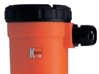
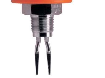
4 5. Operating Principle The KOBOLD liquid level switch NWS is designed as a 2 and 3-wire switch and can be universally used in vessels and pipelines. The NWS operates on the tuning fork principle in air at resonance frequency. A piezoelectric crystal is used for excitation of oscillations and for monitoring the actual oscillation frequency. When the fork is immersed in liquid, the frequency changes: this change is detected electronically and the output signal is changed. The NWS operates as a two-wire switch in series with the load. The simple electronic switch is operated by the liquid. The NWS can also be connected to a PLC through a third terminal. Special Features: The NWS has a switch status indicator with LED, which can be seen continuously through a lens in the cover. The LED flashes approximately once every second, when the NWS has switched off and goes onto a permanent light, when the NWS is switched on. The LED is a visible confirmation that the NWS is working correctly and that the condition of the wet side is correctly indicated. With a selector switch the NWS can be set either as an upper limiter or as a lower limiter. 6. Use in Hazardous Areas (NWS-2E) 6.1 Device function The intrinsically safe NAMUR oscillating fork sensor is used to detect the fill levels of combustible and non-combustible liquids. The sensor is supplied with current from a switching amplifier with an intrinsically safe output circuit in accordance with the NAMUR specification and behaves accordingly when the oscillating fork is dampened by liquid or can oscillate freely. The sensor can be used in all zones in gaseous hazardous areas. Page 4 NWS K06/0214
5 6.2 Commissioning/Installation The devices may be installed in zones 0, 1 and 2. The intrinsically safe circuits must be installed (by specialists) in conformance with the applicable installation requirements (certification document of installer, protected routing of the intrinsically safe circuits, etc.). The devices are constructed in accordance with protection type IP 65. If applicable, they must be protected against adverse environmental conditions. The EU model test certificates must be complied with. Any special regulations contained in them must be followed. The device should only be used for its intended use. The connection with the associated and/or intrinsically safe equipment must be separately checked. The sensors must be grounded to discharge accumulated electrostatic charge. At an ambient temperature area of C the connected electrical cable may be mechanically moved. Furthermore at an ambient temperature area of C the electrical cable must be mounted in a fixed and static manner. The tuning fork should be protected against external hits. The connection area of the plug connection version and the connection cable should be protected against electrostatic charges during its use in zone 0. The sensors are by default produced with 1.5 m long cable or with a plug. In this case a Ci of 8 pf should be taken into account, the internal inductance is negligible. o For longer cable length an additional Lc value of 0.14 nf m -1 and LI value of 0,65 µh m -1 per each meter of supplied cable should be considered. 6.3 Designation Model: NWS***2E* **** II 1 G Ex ia IIC T6 Ga BVS 03 ATEX E 119 IECEx BVS Identification number: 0158 Production-No.: SN: E (consecutively numbered) NWS K06/0214 Page 5
6 6.4 Temperature resistance The values for ambient temperatures ranging from -20 C up to the values indicated in the following table apply to this sensor, depending on the max. temperature of the oscillating forks in the sensor: Ambient temperature 70 C 70 C Medium temperature 75 C 90 C Temperature class T6 T5 7. Mechanical Connection During installation and removal, recognised and applicable engineering practices and regulations shall be observed. When working on electrical and pneumatic plants, the special safety requirements shall be observed. The NWS switch can be installed in containers or piping by screwing it into a threaded mounting flange or other type of mounting device. The threaded connection must be sealed with Teflon (PTFE) tape. Be sure to turn the switch at the hexagonal drive; do not install the switch by turning it at the housing. After installation, the NWS can be rotated up to 330 to locate the M16 cable connection (supplied with the device) in a suitable position. If the switch is installed in a horizontal position, the tuning fork gap should be positioned vertically so that the liquid can drain from it. If the liquid being monitored is of high viscosity, the switch should be installed so that it extends the maximum distance into the container or piping in order to prevent the thick liquid from sticking and accumulating between the fork and the container or pipe wall. If the switch is installed in piping, the tuning fork gap should be positioned so that it is parallel to the pipe axis. Page 6 NWS K06/0214

7 8. Electrical Connection Attention! Be sure that the supply voltage of your system is the same as that specified on the device nameplate. Make sure that the electrical supply lines are de-energised when connecting the device! 8.1 NWS Series wiring with a 2-wire connection Please note: The switch must always be operated in series with a load. The switch must be grounded at terminal 1. The switch draws a continuous operating current of less than 3.5 ma (even when it is "off"). For this reason, it cannot be used for loads that do not allow an off current (such as for gas discharge lamps). The maximum load current for the switch is 500 ma. The user must provide suitable protective measures to ensure that this load limit is not exceeded. NWS K06/0214 Page 7
8 Wiring diagram: 2-wire V AC/DC, series load, I max 400mA PLC connection with 3-wire connection Please note: An integral series resistance is used in the 3-wire circuit to generate a PLC-compliant voltage signal. The signal can be picked up at terminal 4. PLC programming devices or computers from various manufacturers will have different "OFF" threshold voltages. If you should have problems with this setting, please contact us for assistance. Wiring diagram: 3-wire, V S = 24 V DC, output PNP: U HIGH ~ 20 V; U LOW ~ 3.5 V; I max 400 ma Page 8 NWS K06/0214
9 8.2 NWS-...23/24; NWS-...2W/2H; NWS-...2E (ATEX certification) NWS Make sure that the electrical supply lines are de-energised. Connect the device using the M12x1 plug or a connection cable as shown in the wiring diagram below. Matching connectors with different cable lengths are optionally available. Make sure that the installation is properly performed and that the IP protection level is maintained. Wiring diagram NWS-...23/24 (24 V DC ) Wiring diagram NWS-...2W/2H 2 GND (n.c.) 1 +Vs (n.o.) 2 1 +Vs +Vs (n.c.) GND (n.o.) 3 4 Switch Out GND 3 4 Switch Out Wiring diagram NWS-2ES.. (NAMUR, ATEX) E 2 1 +S (n.o.) -S 3 4 +S (n.c.) Cable pin assignment Strand colour NWS-...23/24 NWS-...2W/2H brown +Vs(n.o.) / GND +Vs blue GND / +Vs (n.c.) GND black Switch Out Switch Out Lead-/Pinnumber NWS-...2EF 1 +S (n.o.) 2 ground 3 -S 4 +S (n.c.) NWS K06/0214 Page 9
10 9. Settings 9.1 Settings for NWS Signalling the operating status The NWS has an output status indicator with an LED monitor that can be viewed continuously through a lense in the cover. The LED flashes approximately once every second when the NWS is off. It is continuously illuminated when the NWS is switched on. The LED provides visual confirmation that the NWS is operating correctly and that the status of the wet side is correctly displayed. With its operating mode switch, the NWS can be set to operate as either an N/C contact or an N/O contact Operating mode selector switch The operating mode switch is positioned on the circuit board on the right about the LED. If the switch is operated as an N/C contact (upper limiter), the operating mode must be set to DRY-ON, in order to obtain the maximum fail-safe behaviour. The device completes the circuit in the dry state (empty state) so that a fault at the device or in the wiring results in a voltage drop that causes an alarm to be triggered (break circuit). Conversely, if the switch is to WET-ON, the device operates as an N/O contact (lower limiter) in fail-safe mode, in which case the fork is normally immersed in liquid. Page 10 NWS K06/0214


11 9.1.3 Calibration mode Each appliance is adjusted by the factory to record fluids with density 1,0 kg/l (water). It is not usually necessary to alter this pre-adjustment. In extreme situations, however, such as with very light fluids at high temperatures or highly viscous fluids, which produce a significantly extended reaction time from dry to wet, it can be advantageous to alter the pre-adjustment. In order to attain the calibration mode the Setup button must be activated and held, then the supply voltage must be switched on. After approximately 1 second the LED goes on, after 2 seconds the LED goes out, then let go of the Setup button the appliance stays now in the main menu of the calibration mode. There is a choice of options in the main menu - Switchpoint Calibration, Hysteresis Level and LED Mode. The LED indicates the selected option: Switchpoint Calibration: LED flashes briefly 1x, then LED 2 seconds off. Hysteresis Level: LED flashes briefly 2x, then LED 2 seconds off. LED Mode: LED flashes briefly 3x, then LED 2 seconds off. The option points are repeated in an infinite loop. In order to get access to an option the Setup button must be activated briefly when the LED has signalled the requested option point. Switchpoint Calibration: The "Switchpoint Calibration Mode" is signalled by: LED 1x briefly off, then LED 2 seconds on. Dip the tuning fork as far as the required switchpoint (1/2 2/3 of the fork length) in the medium and activate the Setup button. The calibration is made. A successful calibration is signalled by the LED flashing quickly three times. Hysteresis and LED Mode are set back to default! After calibration the switch back to the main menu takes place. Hysteresis Level: The "Hysteresis Level Mode" is signalled by: LED 2x briefly off, then LED 2 seconds on. Briefly activate the Setup button to get to the submenu. Hysteresis Level 1(approx mm): LED flashes briefly 1x, then LED 2 seconds off. Hysteresis Level 2 (approx mm, Standard): LED flashes briefly 2x, then LED 2 seconds off. Hysteresis Level 3 (approx mm): LED flashes briefly 3x, then LED 2 seconds off. NWS K06/0214 Page 11
12 The choice of options is repeated in an infinite loop. To select an Hysteresis Level, the Setup button must be activated after the flashing of the relevant LED. Three quick flashes of the LED signal that an option has been selected, then the switch back to the main menu is made. LED Mode: The "LED Mode" is signalled by: LED briefly 3x off, then LED 2 seconds on. Briefly activate the Setup button in order to attain the option menu LED Mode. LED Mode 1 (Standard): LED flashes briefly 1x, then LED 2 seconds off. LED shows the status of the switch output LED Mode 2: LED flashes briefly 2x, then LED 2 seconds off. LED indicates whether the tuning fork is wetted or not The choice of options is repeated in an infinite loop. In order to select an "LED Mode" the button must be briefly activated after the relevant flashing of the LED. Three quick flashes of the LED signal that an option has been selected. When the LED Mode has been successfully selected, the switch back to the main menu is made. In order to leave the calibration mode, the appliance must be separated from the voltage supply for approx. 10 seconds Test Function NWS-20 Through the pressing and holding of the setup button, independent of the state of NWS, the switching output can be temporarily switched off. During the test phase, the LED blinks rapidly. Releasing the button returns the NWS after ca. 3 sec. to the current operating condition. 9.2 Settings for NWS-...23/24/2W/2H and NWS-2E Signalling the operating status The NWS has an output status indicator with an LED monitor that can be viewed continuously through a lense in the cover. The LED flashes approximately once every second when the NWS is off. It is continuously illuminated when the NWS is switched on. The LED provides visual confirmation that the NWS is operating correctly and that the status of the wet side is correctly displayed. With its operating mode switch, the NWS can be set to operate as either an N/C contact or an N/O contact. Page 12 NWS K06/0214
13 9.2.2 Selecting operating mode By reversing the polarity of the power supply, the switching function of the NWS-...23/24 can be changed from a N/C contact to a N/O contact. In the case of the NWS-...2W/2H (WHG), the switching function cannot be changed for reasons of safety. This electronic switch opens in case of wetting, a faulty sensor or a power failure. For the NWS-2E the operating modus is selected by connecting the corresponding connector (plug connector or cable pin assignment) (see 8.2). Function Signalling NAMUR-output fork N/C LED on 2.1 ma uncovered LED flashes quickly 0.8 ma covered N/O LED on 2.1 ma covered LED flashes quickly 0.8 ma uncovered Calibration mode NWS-23/24/2W/2H and NWS-2E Each appliance is adjusted by the factory to record fluids with density 1,0 kg/l (water). It is not usually necessary to alter this pre-adjustment. In extreme situations, however, such as with very light fluids at high temperatures or highly viscous fluids, which produce a significantly extended reaction time from dry to wet, it can be advantageous to alter the pre-adjustment. In the calibration mode for NWS-2E, the NAMUR loop current changes with the state of the LED signal. Therefore, the subsequent signal evaluation should be suppressed during the calibration process. In order to attain the calibration mode the test magnet must be placed at the label marking and held, then the supply voltage must be switched on. After approximately 1 second the LED goes on, after 2 seconds the LED goes out, then remove the test magnet the appliance stays now in the main menu of the calibration mode. There is a choice of options in the main menu - Switchpoint Calibration, Hysteresis Level and LED Mode (not NWS-2E). The LED indicates the selected option: Switchpoint Calibration: LED flashes briefly 1x, then LED 2 seconds off. Hysteresis Level: LED flashes briefly 2x, then LED 2 seconds off. LED Mode: LED flashes briefly 3x, then LED 2 seconds off (not NWS-2E). The option points are repeated in an infinite loop. In order to get access to an option the test magnet must be placed briefly when the LED has signalled the requested option point. NWS K06/0214 Page 13
14 Switchpoint Calibration: The "Switchpoint Calibration Mode" is signalled by: LED 1x briefly off, then LED 2 seconds on. Dip the tuning fork as far as the required switchpoint (1/2 2/3 of the fork length) in the medium and activate by placing the test magnet briefly. The calibration is made. A successful calibration is signalled by the LED flashing quickly three times. Hysteresis and LED Mode are set back to default! After calibration the switch back to the main menu takes place. Hysteresis Level: The "Hysteresis Level Mode" is signalled by: LED 2x briefly off, then LED 2 seconds on. Activate by placing the test magnet briefly to get to the submenu. Hysteresis Level 1(approx mm): LED flashes briefly 1x, then LED 2 seconds off. Hysteresis Level 2 (approx mm, Standard): LED flashes briefly 2x, then LED 2 seconds off. Hysteresis Level 3 (approx mm): LED flashes briefly 3x, then LED 2 seconds off. The choice of options is repeated in an infinite loop. To select an Hysteresis Level, the test magnet must be placed briefly after the flashing of the relevant LED. Three quick flashes of the LED signal that an option has been selected, then the switch back to the main menu is made. LED Mode (not NWS-2E): The "LED Mode" is signalled by: LED briefly 3x off, then LED 2 seconds on. Briefly activate the Setup button in order to attain the option menu LED Mode. LED Mode 1 (Standard): LED flashes briefly 1x, then LED 2 seconds off. LED shows the status of the switch output LED Mode 2: LED flashes briefly 2x, then LED 2 seconds off. LED indicates whether the tuning fork is wetted or not The choice of options is repeated in an infinite loop. In order to select an "LED Mode" the test magnet must be placed briefly after the relevant flashing of the LED. Three quick flashes of the LED signal that an option has been selected. When the LED Mode has been successfully selected, the switch back to the main menu is made. In order to leave the calibration mode, the appliance must be separated from the voltage supply for approx. 10 seconds Test function The magnet supplied with the device can be used to switch off the electrical output of the NWS- independent of status of the tuning fork. In this case, the magnet must be placed on the location indicated on the device nameplate. After approximately 2 seconds, the NWS- switches the output off and the LED begins blinking. After the magnet is removed, the output returns after 3 seconds to its previous state. Page 14 NWS K06/0214
15 9.2.5 Selecting operating mode The choice of plug connector or cable pin assignment determines whether the level switch is operated as an N/C contact or an N/O contact (see the section Electrical connection below). 10. Technical Information Fork: stainless steel Process connection: stainless steel Electronic housing: NWS : PAG, glass-fibre-reinforced cover with window, 330 rotatable all other types: stainless steel Process connections: Pipe thread DIN EN , NPT thread, Tri-Clamp, Pipe connection DIN (sanitary connection), Aseptic-connection DIN 11864, DRD flange, Flange B 25 PN 40 DN 2527, Flange B 50 PN 40 DN 2527, Flange ANSI B ", 300 lbs, Flange ANSI B ", 300 lbs Protection: plastic housing: IP 65 (NWS ) stainless steel housing, plug connection: IP 67 stainless steel housing, cable connection: IP 68 Max. operating pressure: Max. medium temp.: 45 bar Flange connection: see pressure steps 130 C (NWS ) 90 C (for all other NWS) short-time 150 C for CIP (valid for all models NWS) Min. medium density 0.8 kg/l (lower on request) Ambient temperature: -20 C C Power supply NWS : VDC/ AC (50/ 60 Hz); 2-wire; 24 VDC, 3-wire NWS-...23/24/2W/2H..: 24 VDC, 3-wire NWS-...2E..(ATEX): Isolation Switching Amplifier to IEC (Namur) necessary (for example: REL-6) Delay: 1 s wet /dry 1 s dry / wet Viscosity: 5000 mm2/s max. at 25 C (influence on the response time) NWS K06/0214 Page 15
16 Hysteresis: Repeatability: Weight: 4 mm vertical, 1 mm horizontal ± 1 mm at ambient temperature 0.5 kg (for R ¾ and ¾ NPT) Electrical Connection: NWS : cable connection: M 16 x 1.5 terminal: max. 1.5 mm 2 (26-14 AWG) capacity: 0.4 A max. at room temp. min. switching current: 7.5 ma leakage current in off-state: < 3.5 ma constant voltage drop: ca. 6 V (2-wire connection) NWS-...23/24/2W/2H..: Overload cut-off (NWS-2x): NWS-...2E.. (ATEX): connector M12x1, 4-pole or 1.5 m fixed cable, 3-pole switching output: O. C. PNP or NPN (factory set), max. 300 ma, short-circuit-proof contact function: N/C or N/O adjustable by switching polarity of supply voltage (only NWS...23/24) In case of thermal overload or excessive current, the unit cust off the load. The triggering of overload protection is indicated by fast blinking of the LED. connector M12x1, 4-pole or 1.5 m cable 2-wire NAMUR output N/C or N/O selectable N/C: 2.1 ma discovered 0.8 ma covered N/O: 0.8 ma discovered 2.1 ma covered Page 16 NWS K06/0214
17 11. Order Codes Example: NWS-R Connection Model Electrical connection Sensor version R ¾ male thread NWS-R = 60 mm (only for R 1 male thread NWS-R25...* Plastic housing NWS-T / NWS-L / NWS-H) ¾ NPT male thread NWS-N = V AC/DC 1 NPT male thread NSW-N25...* cable gland/terminal connect = 70 mm DIN-flange DN 25 NWS-F25... standard version, short DIN-flange DN 50 NWS-F50...* St. steel housing/plug connect. (not for NWS-T / NWS-L) 23S = 24 V DC, PNP, plug M12x1 1 ANSI-flange NWS-A S = 24 V DC, NPN, plug M12x1 0117** = 117 mm 2 ANSI-flange NWS-A50...* 2WS*** = 24 V DC, WHG, PNP, plug M12x1 extended Tri-Clamp DN 40 NWS-T HS*** = 24 V DC, WHG, NPN, plug M12x1 Tri-Clamp DN 50 NWS-T ES = ATEX-approval, plug M12x1 0300** = 300 mm sensor Sanitary DN 40 (DIN 11851) NWS-L40... Sanitary DN 50 (DIN 11851) NWS-L50... St. Steel housing/cable connect. 0500**= 500 mm sensor Aseptic connection NWS-H F = 24 V DC, PNP, 1.5 m cable DN 50 (DIN 11864) 24F = 24 V DC, NPN, 1.5 m cable 1000** = 1000 mm sensor DRD Ø 125 mm flange NWS-D1Z... 2WF*** = 24 V DC, WHG, PNP, 1.5 m cable 2HF*** = 24 V DC, WHG, NPN, 1.5 m cable Special connection NWS-YYY... 2EF = ATEX-approval, 1.5 m cable **only models marked with *are available with sensors in extended version. ***WHG-approval in preparation. XXXX** = please specify special length 4-position in mm (max mm) 12. Service and Maintenance The functional behaviour of these devices is stable, even over long periods or time. Regular adjustments or similar procedures are not required. No maintenance of any type is required. In the event that device faults are noted, this device should be immediately removed from service. The device contains no user-serviceable parts. Return the device to the manufacturer for examination. 13. Trouble Shooting Devices that are operated in hazardous areas must not be modified in any way. Repairs must be performed by trained, qualified service personnel only. Defective devices should normally be returned to the manufacturer for examination. NWS K06/0214 Page 17
18 14. Recommended Spare Parts There are no recommended spare parts. If the device becomes defective, it usually means that there is a fault in the device electronics that must be diagnosed and repaired. In this case, we recommend that the device be returned to the manufacturer for servicing. 15. Disposal Disposal of packaging and used parts shall be done in conformance with the regulations of the country in which the device is installed. Page 18 NWS K06/0214
19 16. Dimensions NWS V AC/DC Plastic housing NWS-...23S/24S NWS-...2WS/2HS 24 V DC Plug connection Ø 40 NWS-...23F/24F NWS-...2WF/2HF 24 V DC Terminal connection Ø NWS-...2ES ATEX Plug connection NWS-...2EF ATEX Cable connection NWS K06/0214 Page 19
20 NWS-R20/N20 (Standard, short) NWS-R25/N25 NWS- N (Standard, long) NWS-F../NWS-A.. Flange version NWS-T.. Tri-clamp L2 L3 DN 25 /PN approx. 47 DN 50 / PN approx. 95 ANSI lbs 17,5 approx. 41 ANSI lbs 22,4 approx. 92 NWS-L.. Sanitary connection (DIN 11851) NWS-H.. Aseptic connection (DIN 11864) Page 20 NWS K06/0214
21 17. Declaration of Conformance We, KOBOLD Messring GmbH, Hofheim-Ts, Germany, declare under our sole responsibility that the product: Level Switch model: NWS -.. to which this declaration relates is in conformity with the standards noted below: EN Safety requirements for electrical equipment for measurement, control and laboratory use 2002 EN A2 Electrical equipment for measurement, control and laboratory use - EMC requirements, industrial area, 2006 Additional for model NWS-***2E* **** EN :2012 EN :2012 EN :2007 Also the following EEC guidelines are fulfilled: 2004/108/ EC (Electromagnetic compatibility) 2006/95/EC (Low voltage guideline) 94/9/EC Equipment and Protective systems intended for use in a potentially Explosive Atmospheres (ATEX 100a) Quality Management Production Certificate number: BVS 09 ATEX ZQS/E110 Notified body: DEKRA Exam GmbH Identification number: 0158 Hofheim, 30. Jan H. Peters M. Wenzel General Manager Proxy Holder NWS K06/0214 Page 21

22 18. Supplement to the EC-Type Examination certificate Page 22 NWS K06/0214
23 NWS K06/0214 Page 23
24 Page 24 NWS K06/0214
25 19. IECEx Certificate NWS K06/0214 Page 25
Liquid Level Switches
 Liquid Level Switches According to the Tuning Fork Principle measuring monitoring analysing N Repeatability: ± mm pmax: 45 bar tmax: 30 C, 50 C (for CIP process) Connections: Pipe screw joints, NPT, Flange,
Operating Instructions for Microwave Level Switch. Model: LNM
 Operating Instructions for Microwave Level Switch Model: LNM 1. Contents 1. Contents...2 2. Note...3 3. Instrument Inspection...3 4. Regulation Use...3 5. Operating Principle...4 6. Mechanical Connection...5
Operating Instructions for Pressure Sensor with Ceramic Sensor Element. Model: SEN-9601
 Operating Instructions for Pressure Sensor with Ceramic Sensor Element Model: SEN-9601 We don t accept warranty and liability claims neither upon this publication nor in case of improper treatment of the
INSTALLATION AND OPERATION MANUAL
 Version 2.2 MS1016 MTF SERIES VIBRATING PROBES FOR LIQUIDS AND HYC-PKK-312 SWITCHING ISOLATOR INSTALLATION AND OPERATION MANUAL Hycontrol Limited, Larchwood House, Orchard Street, Redditch, Worcestershire,
Operating Instructions for Flow Indicator. Model: DAZ
 Operating Instructions for Flow Indicator Model: DAZ 1. Contents 1. Contents... 2 2. Note... 3 3. Instrument Inspection... 3 4. Regulation Use... 3 5. Operating Principle... 3 6. Mechanical Connection...
KFS. Flap-type flow meter. Design and range of application
 Design and range of application The measuring device operates largely independent of viscosity and is suitable for indicating the flow rate of water, acids, alkaline solutions and gases. Every device is
Inductive sensor slot-type SI2-K08-AP7
 SI2-K08-AP7 Slot sensor, height 8 mm Plastic, polypropylene Mechanical end stop, removable, for analog pointer instruments 3-wire DC, 10 30 VDC NO contact, PNP output Cable connection Wiring diagram Type
DMP 343. Industrial Pressure Transmitter. Without Media Isolation. appmeas.co.uk +44 (0)
") DMP 4 Industrial Pressure Transmitter Without Media Isolation accuracy according to IEC 60770: 0.5 % FSO Nominal pressure from 0... 0 mbar up to 0... 000 mbar Product characteristics excellent linearity
DMP 4 Industrial Pressure Transmitter Without Media Isolation accuracy according to IEC 60770: 0.5 % FSO Nominal pressure from 0... 0 mbar up to 0... 000 mbar Product characteristics excellent linearity
DMP 343. Industrial Pressure Transmitter. Without Media Isolation. accuracy according to IEC 60770: 0.35 % FSO. Nominal pressure
 DMP 4 Industrial Pressure Transmitter Without Media Isolation accuracy according to IEC 60770: 0.5 % FSO Nominal pressure from 0... 0 mbar up to 0... 000 mbar Product characteristics excellent linearity
Operating Instructions for Ultrasonic Flowmeter/ -Monitor/ - Counter/ -Dosing Unit. Model: DUK
 Operating Instructions for Ultrasonic Flowmeter/ -Monitor/ - Counter/ -Dosing Unit Model: DUK 1. Contents 1. Contents... 2 2. Note... 3 3. Instrument Inspection... 3 4. Regulation Use... 3 5. Operating
Glass-fibre-reinforced polycarbonate. Dead zone Adaptive or fixed from % 1.5 s adjustable. 20 ms. 60 ms. 60 ms. Approx. 1.
 General data Mounting On linear actuators On quarter turn actuators ARCA-integrated or to VDI/VDE 3847-1 or IEC 534-6 (NAMUR) Range of stroke: 3... 130 mm Integrated to VDI/VDE 3847-2 or VDI/VDE 3845 Angle
Operating Instructions
 Level and Pressure Operating Instructions VEGATOR 620, 621, 622 max. 0 10 min. 0 10 on VEGATOR 622! 6 7 8 9 10 11 12 13 14 in out Contents Contents Safety information... 2 Note Ex area... 2 1 Product description
Intrinsically safe pressure transmitter MBS 4201, MBS 4251, MBS 4701 and MBS 4751
 Data sheet Intrinsically safe pressure transmitter MBS 420, MBS 425, MBS 470 and MBS 475 The intrinsically safe pressure transmitter program is designed for use in hazardous environments and offers a reliable
Operating Instructions for Compact Vortex Flow Meter. Model: DVZ
 Operating Instructions for Compact Vortex Flow Meter Model: DVZ 1. Contents 1. Contents... 2 2. Note... 3 3. Instrument Inspection... 3 4. Regulation Use... 3 5. Operating Principle... 4 6. Mechanical
Design and applications
 Design and applications The measuring device operates largely independent of viscosity and is suitable for indicating the flow rate of water, acids, alkaline solutions and gases. Every device is calibrated
Level and Pressure. Product Information. Vibrating level switches
 Level and Pressure Product Information Vibrating level switches Contents Contents 1 Product description 1.1 VEGAVIB... 3 1.2 VEGASWING... 3 2 Function and application 2.1 Functional principle... 5 2.2
Magnetic Inductive Flow Sensor induq
 Operating manual (Translation) Operating manual... page 1-16 Magnetic Inductive Flow Sensor induq Series VMZ SIKA Ba_VMZ_en 10/2014. Please keep this operating manual for future reference. If the device
MEGGITT MOBREY LTD. MOBREY SQUING Vibrating fork liquid level switch. Product data sheet IP202
 MEGGITT MOBREY LTD MOBREY SQUING Vibrating fork liquid level switch Universal level switch High level alarm duty Overfilling prevention Intrinsically safe models Marine approved models FEATURES Small &
SALES SERVICE +358 (0)
") SALES SERVICE +358 (0)17 262 3555 info@econosto.fi ADCATROL ELECTRO-PNEUMATIC POSITIONERS PE 986 (ATEX) DESCRIPTION The ADCATROL PE986 positioner requires an input signal of 4 20 ma for proportional control
SALES SERVICE +358 (0)17 262 3555 info@econosto.fi ADCATROL ELECTRO-PNEUMATIC POSITIONERS PE 986 (ATEX) DESCRIPTION The ADCATROL PE986 positioner requires an input signal of 4 20 ma for proportional control
SET Installation and Operating Instructions. Level switch for two sensors
 Labkotec Oy Myllyhaantie 6 FI-33960 PIRKKALA FINLAND Tel: + 358 29 006 260 Fax: + 358 29 006 1260 20.2.2013 Internet: www.labkotec.fi 1/14 SET-2000 Level switch for two sensors Copyright 2013 Labkotec
Pressure transmitters MBS 4201, MBS 4251, MBS 4701 and MBS 4751
 060R9345 Instructions Pressure transmitters MBS 4201, MBS 4251, MBS 4701 and MBS 4751 Content Page 1 Description/application 2 Identification 3 Specifications 4 Safety instructions 5 Installation/dimensions
Glass-fibre-reinforced polycarbonate. Dead zone Adaptive or fixed from % 20 ms. 60 ms. 60 ms. Approx. 1.3 kg. Approx. 0.9 kg. Approx. 5.
 General data Mounting On linear actuators On quarter turn actuators ARCA-integrated or to VDI/VDE 3847-1 or IEC 534-6 (NAMUR) Range of stroke: 3... 130 mm Integrated to VDI/VDE 3847-2 or VDI/VDE 3845 Angle
INSTRUCTION MANUAL (ATEX / IECEx)
") INSTRUCTION MANUAL (ATEX / IECEx) STExS1 & STExS2 Sounder For use in Flammable Gas and Dust Atmospheres 1) Warnings DO NOT OPEN WHEN AN EXPLOSIVE ATMOSPHERE IS PRESENT POTENTIAL ELECTROSTATIC CHARGING
INSTRUCTION MANUAL (ATEX / IECEx) STExS1 & STExS2 Sounder For use in Flammable Gas and Dust Atmospheres 1) Warnings DO NOT OPEN WHEN AN EXPLOSIVE ATMOSPHERE IS PRESENT POTENTIAL ELECTROSTATIC CHARGING
ECHOTEL 961/962. Ultrasonic level switches. Loop or line powered D E S C R I P T I O N F E AT U R E S A G E N C Y A P P R O VA L S
 ECHOTEL 961/962 Ultrasonic level switches D E S C R I P T I O N The Echotel 961/962 series utilizes pulse signal technology to detect high or low level alarm(s) in a broad range of viscous to light liquids.
Miniature resistance thermometer Explosion-protected version Model TR34, thread-mounted
 Electrical temperature measurement Miniature resistance thermometer Explosion-protected version Model TR34, thread-mounted WIKA data sheet TE 60.34 Applications Machine building, plant and vessel construction
Expert 1400 / Expert 3400 Submersible Hydrostatic Level Transmitters
 Expert 1400 / Expert 3400 Submersible Hydrostatic Level Transmitters ll 2G EEx ia llc T6 As our products are continuously improved, we reserve the right to make any change in the stated specifications
ED701 General Industry Pressure Transmitter
 ED701 General Industry Pressure Transmitter Standard industrial process connections Complete range of electrical connections 4... 20 ma and Voltage outputs Accuracy: 0.1%, 0.2% and 0.4% FS Quick response
Relative and absolute pressure transmitter type 528
 Relative and absolute pressure transmitter type 528 The compact type 528 pressure transmitter is based upon the Huba Control developed and since over 20 years well proven ceramic technology. These transmitters
DS 400 DS 400. Intelligent Electronic Pressure Switch Completely in Stainless Steel. piezoresistive stainless steel sensor
 GmbH Postal address: House address Fon (+49) 0 22 42-870-0 Postbox 26 Löhestr. 7 Fax (+49) 0 22 42-870-20 http: // www.tematec.de 5759 Hennef 577 Hennef e-mail: team@tematec.de Data Sheet Page /5 Intelligent
OEM radar transmitter, for aggressive media level measurement
 OEM radar transmitter, for aggressive media level measurement C ompact for level measurement up to 20 m 4... 20 ma/hart - 2 wires Adjustable with P C ATEX approvals Type 8136 can be combined with... Type
Mobrey Ultrasonic. MSP422, MSP400RH, and MSP900GH Level Transmitters. Product Data Sheet February 2015 IP2045, Rev EA
 Mobrey Ultrasonic Product Data Sheet February 215 IP245, Rev EA MSP422, MSP4RH, and MSP9GH Level Transmitters Non-contacting measurement with no moving parts Integral LCD and push-buttons as standard for
User manual. Load cell with one built in amplifier KOSD-FA KIMD-FA KEND-FA Load cell with two built in amplifiers KOSD-FAD KIMD-FAD KEND-FAD
 User manual Load cell with one built in amplifier KOSD-FA KIMD-FA KEND-FA Load cell with two built in amplifiers KOSD-FAD KIMD-FAD KEND-FAD Contents Precautions Intended use General 1 Specification 3
Technical Information Smartec CLD18
 TI01080C/07/EN/01.12 71195835 Products Solutions Services Technical Information Smartec CLD18 Compact inductive conductivity measurement for the food and beverage industry Application The compact measuring
Process transmitter Model UPT-20, with pressure port Model UPT-21, with flush diaphragm
 Electronic pressure measurement Process transmitter Model UPT-20, with pressure port Model UPT-21, with flush diaphragm WIKA data sheet PE 86.05 Applications Process technology Machine building and plant
Operating Instructions
 Operating Instructions FLUDEX-EOC system A. Friedr. Flender AG 46393 Bocholt Tel. 02871/92-0 Telefax 02871/92-2596 www.flender.com Contents 1. Application 3 2. Operation 3 3. Fitting 4 3.1 Fitting transmitter
Measuring range: l/h water m³/h air (20 C, bar) Connection: Flange DN 15...
 Connection: Flange DN 15...") Full Metal Variable Area Flow Meter and Counter for Liquids and Gases monitoring analysing BGN Special versions up to 600 bar O Nominal diameter up to DN 150 S2 Measuring range: 0.5-5.0... 13000-130000
Full Metal Variable Area Flow Meter and Counter for Liquids and Gases monitoring analysing BGN Special versions up to 600 bar O Nominal diameter up to DN 150 S2 Measuring range: 0.5-5.0... 13000-130000
Technical Information Smartec CLD18
 TI01080C/07/EN/02.14 71264779 Products Solutions Services Technical Information Smartec CLD18 Compact inductive conductivity measurement for the food and beverage industry Application Compact measuring
Level gauges Series LT Level indicator, switch and transmitter for liquids
 Level gauges Series LT Level indicator, switch and transmitter for liquids Simple construction Resistant under extreme temperature and pressure conditions No risk of leakage Excellent chemical resistance
BGN. All Metal Variable Area Flowmeter and Counter. for liquids and gases
 All Metal Variable Area Flowmeter and Counter for liquids and gases monitoring analysing BGN Measuring range: 0.5-5.0... 13000-130000 l/h water 0.015-0.15... 240-2400 m³/h air (20 C, 1.013 bar) Accuracy
P R o D u c T I n F o R m at I o n. TDR Level Sensor LFP. The clean solution
 P R o D u c T I n F o R m at I o n TDR Level Sensor The clean solution Level sensors The clean solution Product description The is a hygienic level sensor for liquids using TDR technology a process for
Positioner with HART Communication Type 3780
 Positioner with HART Communication Type 780 Application Single-acting or double-acting positioner for attachment to pneumatic control valves. Supplied with an electric input signal from to 20 ma Travels
Intrinsically Safe Pressure Transmitter for applications in hazardous environments and shipbuilding industry Model IS-20-S, IS-21-S, IS-20-F, IS-21-F
 Replacement product: Model IS-3 Electronic Pressure Measurement Intrinsically Safe Pressure Transmitter for applications in hazardous environments and shipbuilding industry Model IS-20-S, IS-21-S, IS-20-F,
Pharma Temperature Sensor TFP-EX
 SENSORS FOR AND BIO. Product Information TFP-EX Pharma Temperature Sensor TFP-EX Application/Specified Usage Temperature measurement: of liquid media in vessels and pipes suitable for applications in potentially
QL55 Series Luminescence Sensor
 Self-contained, microprocessor-based luminescence sensor Features Self-contained design in a robust, compact metal housing High sensitivity Microprocessor-controlled Senses luminescent marks, even on luminescent
Intrinsically Safe Pressure Transmitter for highest pressure applications in hazardous environments Model IS-20-H
 Replacement product: Model IS-3 Electronic Pressure Measurement Intrinsically Safe Pressure Transmitter for highest pressure applications in hazardous environments WIKA Data Sheet PE 81.51 Applications
KMS-2 Exia Magnetostrictive Level Transmitter
 KMS-2 Exia Magnetostrictive Level Transmitter Revision B 11/10/2017 Installation and operating manual Please retain for future use Contents Symbols Used... 1 Safety information... 1 Introduction... 2 Outputs...
Resistance thermometer Model TR30, compact design
 Electrical temperature measurement Resistance thermometer Model TR30, compact design WIKA data sheet TE 60.30 Applications Machine building, plant and vessel construction Propulsion technology, hydraulics
OPTIFLUX 5000 Technical Datasheet
 OPTIFLUX 5000 Technical Datasheet Electromagnetic flowmeter in flanged version Exceptional long-term stability and accuracy For highly aggressive and abrasive fluids Fully vacuum-resistant with high-tech
Operating Instructions for Compact Magnetic-Inductive Flow Meter. Model: MIK
 Operating Instructions for Compact Magnetic-Inductive Flow Meter Model: MIK 1. Contents 1. Contents... 2 2. Note... 3 3. Instrument Inspection... 3 4. Regulation Use... 3 5. Operating Principle... 4 5.1
Electronic temperature switch with display Model TSD-30
 Electrical temperature measurement Electronic temperature switch with display Model TSD-30 WIKA data sheet TE 67.03 Applications Machine tools Hydraulic power packs Coolant and lubrication systems Machine
Level Limit Switch nivotester FTL 325 P
 Technical Information TI 350F/24/ae Level Limit Switch nivotester FTL 325 P With intrinsically safe signal circuit for connection to the Liquiphant and Soliphant measuring sensor Application Level limit
Full Metal Variable Area Flowmeter and Counter Model BGF
 Full Metal Variable Area Flowmeter and Counter for horizontal and vertical mounting measuring monitoring analysing BGF OO Measuring range: 10-100... 6000-60000 l/h water 0.3-3.0... 170-1700 m³/h air (20
Expert 1400 / Expert 3400 Submersible Hydrostatic Level Transmitters
 Expert 1400 / Expert 3400 Submersible Hydrostatic Level Transmitters Class l, Division 1 Group A-D IIC T4 As our products are continuously improved, we reserve the right to make any change in the stated
Echotel Model 910 Ultrasonic Level Switch
 Echotel Model 910 Ultrasonic Level Switch D E S C R I P T I O N Echotel Model 910 Level Switches utilize ultrasonic contact technology for measuring level in clean liquid applications. The dual conduit
OEM miniature resistance thermometer Models TR31-3 and TR31-K, thread-mounted
 Electrical temperature measurement OEM miniature resistance thermometer Models TR31-3 and TR31-K, thread-mounted WIKA data sheet TE 60.31 further approvals see page 10 Applications Machine building, plant
Target disk flowmeter for liquids and gases
 Target disk flowmeter for liquids and gases Metallic, simple and robust construction Available for all flow directions Suitable for extreme pressure and temperature conditions Low pressure drop Straight
Brunata Optuna H Ultrasonic energy meter Type 775 Installation Guide Edition 1.2
 Ultrasonic energy meter Type 775 Installation Guide Edition 1.2 UK-QB101575 / 29.05.2012 Brunata a/s is a Danish owned company. We have more than 90 years of experience within developing and producing
Inductive Conductivity Meter ILM
 1 Product Information ILM-2 ILM-3 Inductive Conductivity Meter ILM f o o d Application / Specified Usage Authorizations Inductive measurement of the specific conductivity of liquid media in the range of
Coriolis Massflowmeter
 Coriolis Massflowmeter for liquids and gas measuring monitoring analysing Measuring range: 0-0.8 kg / h 0-65 000 kg / h water Accuracy: ± 0.1 of reading ±zero-point stability (liquids) pmax: PN40 tmax:
Nivotester FTR325. Technical Information. 1-channel switch amplifier for the microwave barrier Soliwave FDR50/FQR50
 Technical Information Nivotester 1-channel switch amplifier for the microwave barrier Soliwave FDR50/FQR50 Area of application The Nivotester is suitable as a 1-channel switch amplifier for the Soliwave
User manual. Load cell with one built in amplifier KOSD-FA KIMD-FA KEND-FA Load cell with two built in amplifiers KOSD-FAD KIMD-FAD KEND-FAD
 User manual Load cell with one built in amplifier KOSD-FA KIMD-FA KEND-FA Load cell with two built in amplifiers KOSD-FAD KIMD-FAD KEND-FAD Contents Precautions Intended use General 1 Specification 3
FMG90 Series Electromagnetic Flow Meter
 . FMG90 Series Electromagnetic Flow Meter - 2 - Series FMG90 Series FMG90 Table of contents page 0 About this operating manual... 4 1 Device description... 5 1.1 Delivery, unpacking and accessories...
Submersible pressure sensor For water and wastewater Model LW-1
 Replacement product: Model LF-1 Level measurement Submersible pressure sensor For water and wastewater Model LW-1 WIKA data sheet LM 40.03 Applications Level measurement in rivers and lakes Deep well and
Operating Manual * * Differential pressure transmitter. Table of Contents. 1 Safety guidelines. 1.1 General Information
 *09005137* BA_EN_DE50 Rev.A 11/12 *09005137* d e v e l o p i n g s o l u t i o n s DE50 Operating Manual Differential pressure transmitter Table of Contents 1 Safety guidelines 2 Application purpose 3
Coriolis Mass Flow Meter Model TM
 Coriolis Mass Flow Meter for liquids and gas measuring monitoring analysing TM S5 Measuring range: 0-0.8 kg / h 0-65000 kg / h water Accuracy: ± 0.1 of reading ± zero-point stability (liquids) p max :
Magnetic Inductive Flowmeter
 Magnetic Inductive Flowmeter for conductivity liquids measuring monitoring analysing Measuring range: up to 10 m/s Accuracy: ±1.5% of reading ±0.5% full scale pmax: PN40 tmax: -40 +150 C Connection: flange
Digital temperature transmitter for resistance sensors Model T15.H, head mounting version Model T15.R, rail mounting version
 Temperature Digital temperature transmitter for resistance sensors Model T15.H, head mounting version Model T15.R, rail mounting version WIKA data sheet TE 15.01 for further approvals see page 10 Applications
Resistance thermometer Model TR30, compact design
 Electrical temperature measurement Resistance thermometer Model TR30, compact design WIKA data sheet TE 60.30 Applications Machine building, plant and vessel construction Propulsion technology, hydraulics
KDS. All Metal Variable Area Flowmeter. for Liquids and Gases
 All Metal Variable Area Flowmeter for Liquids and Gases measuring monitoring analysing : 0.1-1... 20-200 water 3-30 Nm3/h... 600-6000 Accuracy: ±3 % of full p max : 420 bar; t max : 130 C Connection: ¼"
KPS Turbidity Meter User s Manual
 KPS Turbidity Meter User s Manual Küppers Elektromechanik GmbH Quality system certified to DIN ISO 91 Contents Product description... page 3 Technical data... page 3 Dimensions... page 4 Getting started...
GESTRA Steam Systems LRS English. Installation & Operating Instructions Conductivity Switch LRS 1-50
 GESTRA Steam Systems LRS 1-50 EN English Installation & Operating Instructions 819223-02 Conductivity Switch LRS 1-50 Contents Important notes Page Usage for the intended purpose...4 Function...4 Safety
Installation and Operational Instructions for ROBA -switch Type 017._00.2
 OBA -switch Type 017._00.2 Guidelines on the Declaration of Conformity A conformity evaluation has been carried out for the product in terms of the EC Low Voltage Directive 2014/35/ EC and the EMC Directive
Intrinsically safe pressure transmitter For applications in hazardous areas Models IS-20-S, IS-21-S, IS-20-F, IS-21-F
 Replacement product: Model IS-3 Electronic pressure measurement Intrinsically safe pressure transmitter For applications in hazardous areas Models IS-20-S, IS-21-S, IS-20-F, IS-21-F WIKA data sheet PE
TMU. Coriolis Mass Flow Meter. for liquids and gas
 Coriolis Mass Flow Meter for liquids and gas measuring monitoring analysing TMU S5 OO Measuring range: 0-60 kg/h 0-2200 t/h water OO Accuracy: ± 0.1% of reading ±zero point stability (from liquids up to
SATRON VB Pressure Transmitter
 SATRON VB pressure transmitter belongs to the series V transmitters. SATRON VB is userfriendly, through the ball valve mounted transmitter which is used for 04 kpa... 03 MPa ranges. The transmitter communicates
Servomotor for butterfly valves VF, VFH. delta-elektrogas.com EE157-01/16
 MZ Servomotor for butterfly valves VF, VFH delta-elektrogas.com EE157-01/16 MZ Servomotor Contents Description.... 2 Features........ 2 Functioning and application..... 3 Technical specifications......
Soliphant T FTM20, FTM21
 Technical Information Soliphant T FTM20, FTM21 Level limit switch Robust vibration limit switch for bulk solids, also for dust incendive hazardous areas Application Soliphant T is a robust level limit
OPTITEMP TT 10 C/R Technical Datasheet
 OPTITEMP TT 10 C/R Technical Datasheet Analogue 2-wire temperature transmitter Temperature linear 4...20 ma output Rangeable with solder pads and potentiometers Easy wiring through large center hole The
KAL-K. Electronic Flow Monitor. for liquids. Range: approx cm/s. p max : 100 bar. Temperature of medium: C Option: 0...
 Electronic Flow Monitor for liquids measuring monitoring analysing KAL-K Range: approx. 4-200 cm/s p max : 100 bar Temperature of medium: -20... +80 C Option: 0... +120 C Process connection: G ¼, G ½,
Digital Input Output Module 24 V for Ex n Zone 2 Series 9472/35
 www.stahl.de > 16 channels can be adjusted in pairs as digital inputs or outputs > Suitable for NAMUR proximity switches, 3-wire PNP proximity switches, contacts and solenoid valves (24 V / 0.5 A). > Up
Liquiphant T FTL20H. Technical Information
 Technical Information Liquiphant T FTL0H Level limit switch Level limit switch for liquids in the foodstuff industry, compact design, housing made of corrosion-resistant stainless steel Application The
Technical Information Condumax CLS21D/CLS21
 TI00085C/07/EN/14.14 71268310 Products Solutions Services Technical Information Condumax CLS21D/CLS21 Conductivity sensors, analog or digital with Memosens technology Cell constant k = 1.0 cm 1 Application
ph or ORP Transmitter
 ph or ORP Transmitter Programmable outputs: two transistor and single or dual analog 4-20 ma (Process + Temp) Removable backlighted display Universal process connection Compatible with 120 mm ph/ ORP probes
Mid-West. Instrument. Model 140 Electrical Installation and Operating Instructions. Gauge Front ELECTRICAL
 Mid-West Instrument BULLETIN NO. ELEC-IM140/11A Replaces ELEC-IM140-141/09A ELECTRICAL Gauges with switches have one or two SPST or SPDT hermetically sealed adjustable set point reed switch assemblies.
OPTIMASS 1000 Technical Datasheet
 OPTIMASS 1000 Technical Datasheet Sensor for mass flow First choice for universal applications Best price-performance ratio A wide range of options available with no restrictions The documentation is only
Level Limit Switch nivotester FTL 370, FTL 372
 Technical Information TI 98F/00/en Limit Switch nivotester FTL 370, FTL 37 With intrinsically-safe signal circuits for connection to sensors Liquiphant, Nivopuls, Soliphant. Features at a Glance High operational
WATERFLUX 3000 Quick Start
 WATERFLUX 3000 Quick Start Electromagnetic flow sensor The documentation is only complete when used in combination with the relevant documentation for the signal converter. KROHNE CONTENTS WATERFLUX 3000
Process display RIA 261
 Technical Information TI 083R/24/ae Process display RIA 261 Digital loop powered field display for 4 to 20 ma current loops Features and Benefits Loop powered display, no additional power supply cable
RTD Temperature Sensor omnigrad T -TSM 480, TR 480. Hygienic RTD sensor with Pt 100, class A TSM 480 with electronics programmable via PC
 Technical Information TI 273T/02/en 60021667 RTD Temperature Sensor omnigrad T -TSM 480, TR 480 Hygienic RTD sensor with Pt 100, class A TSM 480 with electronics programmable via PC Application The Omingrad
Technical Information Nivector FTC968, FTC968Z
 TI0007F/00/EN/7.6 7494 Products Solutions Services Technical Information Nivector FTC968, FTC968Z Capacitance Point level switch for powder and fine-grained bulk solids Application The Nivector is a small-sized
Rosemount 848L Logic Transmitter with FOUNDATION Fieldbus
 Logic Transmitter with FOUNDATION Fieldbus Integrates Discrete I/O on a FOUNDATION Fieldbus H1 Segment Reduces Installation and Maintenance Costs with a Single Network for Analog and Discrete devices Easily
CE620. Piezoelectric accelerometer with integrated electronics. IECEx
 Piezoelectric accelerometer with integrated electronics FEATURES» From the Vibro-Meter product line» Voltage output signal: 100 or 500 mv/ g» Frequency response: 2 Hz to 10 khz» Temperature range: 55 to
Digital temperature transmitter Model T15.H, head mounting version Model T15.R, rail mounting version
 Electrical temperature measurement Digital temperature transmitter Model T15.H, head mounting version Model T15.R, rail mounting version WIKA data sheet TE 15.01 Applications Process industry Machine building
Operating instructions Contrast sensor O5K / / 2016
 Operating instructions Contrast sensor O5K500 707 / 00 / 06 Contents Preliminary note. Symbols used Functions and features Installation. Installation conditions Operating and display elements 5 5 Electrical
RAD-IN/OUT-8D. Digital extension modules for the bidirectional wireless system. INTERFACE Data sheet _en_05. 1 Description
 RAD-IN/OUT-D Digital extension modules for the bidirectional wireless system INTERFACE Data sheet 102122_en_0 PHOENIX CONTACT 2010-02-2 1 Description The RAD-ISM-...-SET-BD-BUS-ANT bidirectional wireless
Operator Manual. Transmitters Series KAT-... Analog transmitters in 2-wire technique
 Operator Manual Transmitters Series KAT-... Analog transmitters in 2-wire technique Important Safety Notes! In the case of non-observance of the installation and safety notes or improper use of the transmitter
Submersible pressure sensor For oils and fuels Model LF-1
 Level measurement Submersible pressure sensor For oils and fuels Model LF-1 WIKA data sheet LM 40.04 Applications Level measurement in vessel and storage systems for oils and fuels Overfilling and dry-run
omnigrad T - TSM 480, TR 480. Technical Information. RTD Temperature Sensor Hygienic design TSM 480 with electronics programmable via PC
 Technical Information omnigrad T - TSM 480, TR 480 RTD Temperature Sensor Hygienic design TSM 480 with electronics programmable via PC Application areas The onmigrad T easytemp TSM 480 and TR 480 thermometers
Mass Flowmeter CoriolisMaster FCM2000
 Contents Data Sheet Mass Flowmeter CoriolisMaster FCM2000 Coriolis Mass Flowmeters are used for high precision measurement of mass flow and density. The fluid need not be electrically conductive. No moving
WATERFLUX 3000 Quick Start
 WATERFLUX 3000 Quick Start Electromagnetic flowmeter The documentation is only complete when used in combination with the relevant documentation for the signal converter. KROHNE CONTENTS WATERFLUX 3000