The New and Improved Carolina Windom Antenna and ½ Wave End Fed 20 Meter Vertical and Sloping Wire Antennas. EZNEC analysis by Pete Rimmel, N8PR
|
|
|
- Deborah Reynolds
- 6 years ago
- Views:
Transcription
1 The New and Improved Carolina Windom Antenna and ½ Wave End Fed 20 Meter Vertical and Sloping Wire Antennas EZNEC analysis by Pete Rimmel, N8PR
2
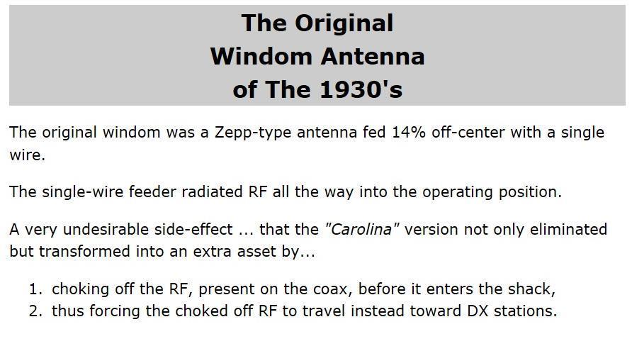
3 Keeps RF off the Coax below this point
4
/")
5 / (part of)/
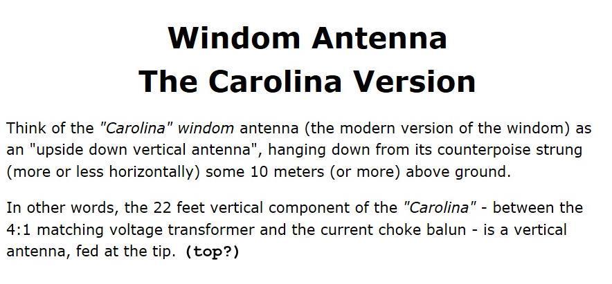
6 That may all be true if the antenna is strung out horizontally. If it is held up in the middle and is in an inverted vee configuration is this still true? I suspect that the vertical polarization from the sloping wires creates interesting interference with the 22 ft section. The EZNEC plots will show how the antenna actually radiates, and where
7 I have not included 160 M, but you will see that the pattern on the 80 and 40 meter bands is pretty much straight up a cloud warmer. Yes, it omni-directional, but only at high take-off angles.

8 NOTE: Every antenna is affected by the ground system under it. That is why we get different take-off angles dependent on height above ground. Otherwise, the Antennas would all radiate as if they were in free space!
9 We will look at the elevation plots of the antenna at 33 feet then at 66 feet For the bands Meters. (I have ignored the WARC bands for simplicity) BUT, FIRST, some basic antenna theory: Every antenna above real ground has a pattern That is affected by its height above ground By its length, and by its orientation.
10 In the ELEVATION plots we will be looking at, the plots show where the RF goes, in various takeoff angles, due to the interaction of the signal in the far field with the reflected RF signal where the ground acts like a mirror.
11 AND Because I was asked to, I have plotted the ½ wave 20 meter end fed antennas and a 20 Meter Dipole up 33 feet. We will look at those first, to see what good plots Might look like!
 29 degree elevation plot (max.")
12 Meter Dipole up 33 feet Azimuth plot (above) 29 degree elevation plot (max. takeoff angle) Axis of antenna 3 D plots looking down on wire (above) and looking end on (below) 29 deg.

13 This is a ½ wave 20 Meter vertical end fed wire Notice the symmetrical pattern. Each line around the circle is 5 degrees deg. 3 D azimuth plot of antenna Looking down from the top Side view of antenna 3D elevation plot


14 This is the ½ wave 20 meter sloping wire with the wire 30 degrees from vertical. Note the null off the end and the pattern better broadside than in line with the antenna


15 This is the ½ wave end fed sloping wire with the wire 45 degrees to the ground. Notice that the pattern is better off the sides than in the direction of the slope, or away from the slope. If there were a metal support holding the wire up, there might be some directivity to the right
16 Now for Sandy s antenna Here is the actual Carolina Windom antenna that I modeled: 22 feet
17 We know that at 33 ft this is a real cloud warmer too low for DX on 80 Meters
18 Even at 66 ft this antenna would be considered a cloud warmer. Most of the RF is going up more than 45 degrees, and not being refracted back to earth at any distance. However, some low angle RF does get to DX stations.


19 80 meter paterns (up 33 ft) Pretty much what you would expect
20 At 33 ft, on 40 M the antenna is only 1/4 wavelength high, and although some RF has low angle takeoff most is still higher than 45 degrees. Notice the effect that the longer end has on the somewhat asymmetrical pattern db/ dipole 1.29 dbi


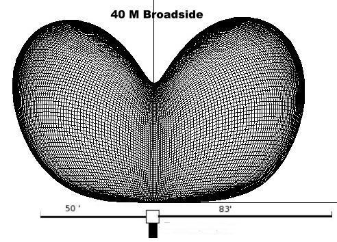
21 40 Meter Antennas up 33 ft
22 At 66 feet 1/2 wavelength high, the antenna has a good pattern on 40 Meters, and some gain over a dipole in the direction of its major lobe. BUT, remember, a dipole has a similar pattern, with peaks and nulls db/ dipole 5.94 dbi
23 3.8 dbi Even up 1/2 wavelength, the antenna on 20 Meters does not havea low takeoff angle is the antenna too long? Remember those pretty dipole patterns? Check these out


24 Meter patterns - Antennas up 33 feet Previous page pretty pattern is the green vertical cut in the radiation pattern
25 5.1 dbi Notice that even up 1 wavelength, much of the RF is going UP
26 1.26 dbi
27 6.88 dbi Note that at 66 feet the 22 ft vertical section interacts with the longer horizontal Leg to give a whopping 4.58 db (over a dipole) at 50 degrees takeoff.


28 15 Meter patterns up 33 ft
29 At 1 wavelength on 10 M we get a nice low takeoff angle, but ~1.1 db less than a dipole dbi

30 10 Meter patterns up 33 ft Notice how the pattern is pulled toward the ends of the wires and is better than the broadside pattern
31 At 2 WL high, this seems to be a good low angle antenna, with high components, too dbi
32 Now let s take a look at the azimuth pattern for each band 33 feet up first and then 66 feet up after that I have chosen the best takeoff angle for each band as shown on the elevation plots
33 10 Meters 5.3 dbi
34 10 Meters 7.3 dbi
35 15 Meters 3.93 dbi
36 15 Meters 7.37 dbi
37 Meters dbi
38 Meters 0.00 dbi
39 Meters 1.36 dbi
40 Meters 3.04 dbi
41 20 Meters 6.75 dbi
42 40 Meters 3.77 dbi
43 40 Meters 5.7 dbi
44 80 Meters 1.49 dbi
45 OK, So what is causing all this confusion in the patterns? Why are they not like the patterns we are used to seeing from a dipole or yagi? Let s look at the wires, themselves, and where the most currents are flowing:
46 80 Meters Since the top 2 wires total length is 133 ft, it acts like a half wave dipole, as expected.
47 40 Meters Currents pretty much like a full wave antenna
48 20 Meters
49 15 Meters
50 10 meters
51 SO What have we learned? The currents and patterns certainly are confusing Signals do not go cleanly broadside or in a omni-directional pattern. Yes, the RF radiates both in line and perpendicular to the axis of the wires. Yes, there are both low and high takeoff angle patterns. Is it better than a dipole, Extended Double Zepp or G5RV? That is up to you All the antennas radiate the RF put into them, I guess it just matters if there is someone out there where the RF goes, to call you! 73, de
ANTENNAS Wires, Verticals and Arrays
 ANTENNAS Wires, Verticals and Arrays Presented by Pete Rimmel N8PR 2 1 Tonight we are going to talk about antennas. Anything that will conduct electricity can be made to radiate RF can be called an antenna.
Chapter 6 Antenna Basics. Dipoles, Ground-planes, and Wires Directional Antennas Feed Lines
 Chapter 6 Antenna Basics Dipoles, Ground-planes, and Wires Directional Antennas Feed Lines Some General Rules Bigger is better. (Most of the time) Higher is better. (Most of the time) Lower SWR is better.
Vertical or horizontal antenna for limited space
 Vertical or horizontal antenna for limited space If you have very limited space for a DX antenna, you may consider vertical, because it has low angle of radiation. But vertical polarization involves high
Beams and Directional Antennas
 Beams and Directional Antennas The Horizontal Dipole Our discussion in this chapter is about the more conventional horizontal dipole and the simplified theory behind dipole based designs. For clarity,
Antennas 101 Don t Be a 0.97 db Weakling! Ward Silver NØAX
 Antennas 101 Don t Be a 0.97 db Weakling! Ward Silver NØAX Overview Antennas 101 2 Overview Basic Antennas: Ground Plane / Dipole How Gain and Nulls are Formed How Phased Arrays Work How Yagis Work (simplified)
The Fabulous Dipole. Ham Radio s Most Versatile Antenna
 The Fabulous Dipole Ham Radio s Most Versatile Antenna 1 What is a Dipole? Gets its name from its two halves One leg on each side of center Each leg is the same length It s a balanced antenna The voltages
Transforms and electrical signal into a propagating electromagnetic wave OR vise versa. - Transducer goes both ways. TX and RX antennas have
 Gary Rondeau AF7NX Transforms and electrical signal into a propagating electromagnetic wave OR vise versa. - Transducer goes both ways. TX and RX antennas have different jobs. For TX want to generate as
CHAPTER 8 ANTENNAS 1
 CHAPTER 8 ANTENNAS 1 2 Antennas A good antenna works A bad antenna is a waste of time & money Antenna systems can be very inexpensive and simple They can also be very expensive 3 Antenna Considerations
N0GW Log Periodic Installation
 N0GW Log Periodic Installation I am particularly happy with my HF log periodic beam antenna installation. This is my first tower mounted, rotatable, beam antenna. Before retiring and moving to the Ozarks,
Basic Wire Antennas. Part II: Loops and Verticals
 Basic Wire Antennas Part II: Loops and Verticals A loop antenna is composed of a single loop of wire, greater than a half wavelength long. The loop does not have to be any particular shape. RF power can
stacking broadside collinear
 stacking broadside collinear There are three primary types of arrays, collinear, broadside, and endfire. Collinear is pronounced co-linear, and we may think it is spelled colinear, but the correct spelling
4/29/2012. General Class Element 3 Course Presentation. Ant Antennas as. Subelement G9. 4 Exam Questions, 4 Groups
 General Class Element 3 Course Presentation ti ELEMENT 3 SUB ELEMENTS General Licensing Class Subelement G9 Antennas and Feedlines 4 Exam Questions, 4 Groups G1 Commission s Rules G2 Operating Procedures
Antennas Demystified Antennas in Emergency Communications. Scott Honaker N7SS
 Antennas Demystified Antennas in Emergency Communications Scott Honaker N7SS Importance of Antennas Antennas are more important than the radio A $5000 TV with rabbit ears will have a lousy picture Antennas
Design of a Delta Loop September 26, 2016
 Design of a Delta Loop September 26, 2016 by K0ZR Introduction Why a Delta loop? A Delta loop can be made to radiate a horizontal or vertically polarized signal. In most cases one chooses the vertical
Newcomers And Elmers Net: Wire Antennas Robert AK3Q
 Newcomers And Elmers Net: Wire Antennas 02-07-16 Robert AK3Q Wire antennas represent one of the greatest values in the radio hobby world. For less than the cost of a good meal out on the town you can buy
The Long Wire Loop: an Omnidirectional, Multiband, Low Angle Radiator. By Steve Cerwin, WA5FRF
 The Long Wire Loop: an Omnidirectional, Multiband, Low Angle Radiator By Steve Cerwin, WA5FRF Introduction: Something Old and Something New As the name implies, long wire loop is a marriage of the venerable
Chapter 5.0 Antennas Section 5.1 Theory & Principles
 Chapter 5.0 Antennas Section 5.1 Theory & Principles G3C11 (B) p.135 Which of the following antenna types will be most effective for skip communications on 40-meters during the day? A. A vertical antenna
Using EZNEC To Compare Antennas Part 2. Bill Leonard N0CU
 Using EZNEC To Compare Antennas Part 2 Bill Leonard N0CU Topics How polarization affects antenna performance How ground type affects antenna performance Example 1: 48 Shunt Fed Tower as 40M Vertical Initially,
THE SATURN A simple portable antenna with a big kick!
 THE SATURN A simple portable antenna with a big kick! That s pretty much it a long fishing pole and some wires. A game:. find the small proto attached to the antenna! INTRO: There are many among us who
HF Wire Antennas with Gain
 Learning Unit 5 HF Wire Antennas with Gain Objectives and Overview: Take the student to the next step beyond the half-wave dipole and introduce wire antennas with enhanced directivity and gain. The concept
Table of Contents. MFJ-1778 G5RV Multiband Antenna
 Table of Contents MFJ-1778 G5RV Multiband Antenna Introduction... 1 Theory Of Operation... 1 80 meter band:... 1 40 meter band:... 1 30 meter band:... 2 20 meter band:... 2 17 meter band:... 2 15 meter
Install as much wire/tubing as possible Electrically short antennas Minimize matching losses Good ground for verticals Maximizes antenna efficiency
 Jim Wolf KR9U Install as much wire/tubing as possible Electrically short antennas Minimize matching losses Good ground for verticals Maximizes antenna efficiency Far-away ground conditions determine low
Least understood topics by most HAMs RF Safety Ground Antennas Matching & Feed Lines
 Least understood topics by most HAMs RF Safety Ground Antennas Matching & Feed Lines Remember this question from the General License Exam? G0A03 (D) How can you determine that your station complies with
CHAPTER 5 PRINTED FLARED DIPOLE ANTENNA
 CHAPTER 5 PRINTED FLARED DIPOLE ANTENNA 5.1 INTRODUCTION This chapter deals with the design of L-band printed dipole antenna (operating frequency of 1060 MHz). A study is carried out to obtain 40 % impedance
Yagi Antenna Tutorial. Copyright K7JLT 1
 Yagi Antenna Tutorial Copyright K7JLT Yagi: The Man & Developments In the 920 s two Japanese electrical engineers, Hidetsugu Yagi and Shintaro Uda at Tohoku University in Sendai Japan, investigated ways
Characteristics of HF Coastal Radars
 Function Characteristics System 1 Maximum operational (measurement) range** Characteristics of HF Coastal Radars 5 MHz Long-range oceanographic 160-220 km average during (daytime)* System 2 System 3 System
ANTENNA BASICS FOR BEGINNERS
 ANTENNA BASICS FOR BEGINNERS PART 2 -DIPOLES DIPOLES -General MULTIBAND DIPOLES RF CHOKES 1 DIPOLES Several different variations of the dipole are also used, such as the folded dipole, short dipole, cage
Coming next: Wireless antennas for beginners
 Coming next: Wireless antennas for beginners In other rooms: Logbook of the World (Sussex Suite) SO2R contest operation (Stable Suite) Wires for your wireless: Simple wire antennas for beginners dominic
ANTENNAS 101 An Introduction to Antennas for Ham Radio. Lee KD4RE
 ANTENNAS 101 An Introduction to Antennas for Ham Radio Lee KD4RE Prepared for Presentation at the Vienna Wireless Society, 13 January 2017 So What is an Antenna Anyway? We are all familiar with wire antennas
Last year I described several Low Band RX antennas that would enable you to hear DX stations on 160, 80 and 40M. This will show you how to build
 Last year I described several Low Band RX antennas that would enable you to hear DX stations on 160, 80 and 40M. This will show you how to build transmit antennas that will help you break the pileups!
General License Class Chapter 6 - Antennas. Bob KA9BHD Eric K9VIC
 General License Class Chapter 6 - Antennas Bob KA9BHD Eric K9VIC Learning Objectives Teach you enough to get all the antenna questions right during the VE Session Learn a few things from you about antennas
Choosing Your First HF Antenna
 The American Radio Relay League Choosing Your First HF Antenna Greater Fairfield Amateur Radio Assn May 1, 2017 Joel R. Hallas, W1ZR Contributing Editor, QST ARRL Copyright 2017, Joel Hallas, all rights
Chapter 9 Antennas and Feedlines
 Chapter 9 Antennas and Feedlines Basics of Antennas Antenna Radiation Patterns. Graphical representation of spatial distribution of energy around an antenna. 3D = Full representation. 2D = Slice through
Contesting with Verticals & VDAs. Pete VE3IKV / VA3RA / VP2EAT
 Pete VE3IKV / VA3RA / VP2EAT Verticals means both gain-type HF monoband verticals and vertical directional arrays (VDAs) Object is to keep the main vertical radiation pattern as low as possible (
L. B. Cebik, W4RNL. 1. You want to get on 160 meters for the first time (or perhaps, for the first time in a long time).
.") L. B. Cebik, W4RNL The following notes rest on a small set of assumptions. 1. You want to get on 160 meters for the first time (or perhaps, for the first time in a long time). 2. You want to set up the
L. B. Cebik, W4RNL The following notes rest on a small set of assumptions. 1. You want to get on 160 meters for the first time (or perhaps, for the first time in a long time). 2. You want to set up the
Antenna Fundamentals
 HTEL 104 Antenna Fundamentals The antenna is the essential link between free space and the transmitter or receiver. As such, it plays an essential part in determining the characteristics of the complete
Antenna simulations Part 2
 Antenna simulations Part 2 Pekka Ketonen OH1TV 27.1.2011 OH1TV 1 Outline Part 1 Some principles in antenna design typical steps in design process Opposite Voltage Feed 2 phased verticals on 80m 2 over
Antennas! November 2018
 1 Antennas! November 2018 Agenda 6PM Show and Tell plus Demos in the Park 7PM Welcome: new members and visitors Announcements Antenna Overview Alpha Loop Antenna N6IET Vertical Colinear WB6MMQ Whip Dipole
Antenna Fundamentals Basics antenna theory and concepts
 Antenna Fundamentals Basics antenna theory and concepts M. Haridim Brno University of Technology, Brno February 2017 1 Topics What is antenna Antenna types Antenna parameters: radiation pattern, directivity,
Maximum-Gain Radial Ground Systems for Vertical Antennas
 Maximum-Gain Radial Ground Systems for Vertical Antennas Al Christman, K3LC Abstract This article compares the peak gain generated by quarter-wave vertical-monopole antennas when they are installed over
Weekend Antennas No. 5 The "Compact Quad" Multiband Antenna
 Weekend Antennas No. 5 The "Compact Quad" Multiband Antenna When I relocated to Johannesburg I needed a new multiband HF antenna. Since I was staying in a rented house a tower was out of the question,
Feed Line Currents for Neophytes.
 Feed Line Currents for Neophytes. This paper discusses the sources of feed line currents and the methods used to control them. During the course of this paper two sources of feed line currents are discussed:
The Multiband Tuned Doublet Antenna
 Editors Note: This article first appeared in the December 1999 issue of The Reflector. The Editors thought it might be useful to the many newly-licensed radio amateurs who have joined our ranks to reprint
Amateur Radio License. Propagation and Antennas
 Amateur Radio License Propagation and Antennas Todays Topics Propagation Antennas Propagation Modes Ground wave Low HF and below, ground acts as waveguide Line-of-Sight (LOS) VHF and above, radio waves
Working Bouvet with the Innovative and Cheap N6MW, Bill Wortman
 Working Bouvet with the Innovative and Cheap N6MW, Bill Wortman Trying to work the upcoming early 2018 Bouvet Dxpedition for an all time new one (ATNO as we say) is a serious challenge for those with only
Antenna Design Seminar
 Antenna Design Seminar What we are going to cover This seminar will cover the design concepts of a variety of broadcast antennas that relates to the design of TV and FM antennas. We will first look at
DX University: Antennas
 DX University: Antennas 29 August 31 Kai Siwiak, KE4PT Prepared for N4II s s DX-University series Sponsored by the South Florida DX Association No Antenna Theory, Just Results What does it take to work
Antennas and Propagation Chapters T4, G7, G8 Antenna Fundamentals, More Antenna Types, Feed lines and Measurements, Propagation
 Antennas and Propagation Chapters T4, G7, G8 Antenna Fundamentals, More Antenna Types, Feed lines and Measurements, Propagation =============================================================== Antenna Fundamentals
Elevation and Pseudo-Brewster Angle Formation of Ground- Mounted Vertical Antennas
 Robert J. Zavrel, Jr., W7SX PO Box 9, Elmira, OR 97437; w7sx@arrl.net Elevation and Pseudo-Brewster Angle Formation of Ground- Mounted Vertical Antennas The formation of the elevation pattern of ground
NVIS, Another Look. Tom Sanders, W6QJI Ed Bruette, N7NVP
 NVIS, Another Look Tom Sanders, W6QJI Ed Bruette, N7NVP Regional Communications N.V.I.S. Near Vertical Incidence Skywave What is NVIS? Near Vertical Incident Skywave Cloud Warmer Propagation Theory NVIS
Other Arrays CHAPTER 12
 CHAPTER 12 Other Arrays Chapter 11 on phased arrays only covered arrays made of vertical (omnidirectional) radiators. You can, of course, design phased arrays using elements that, by themselves, already
The M-Quad. By John Portune W6NBC
 Author s Note The M-Quad A revolutionary new antenna design, from recent studies into a well-known mathematical curiosity. It s a practical 2m antenna with extraordinary performance you can build. By John
UNIT-3. Ans: Arrays of two point sources with equal amplitude and opposite phase:
 `` UNIT-3 1. Derive the field components and draw the field pattern for two point source with spacing of λ/2 and fed with current of equal n magnitude but out of phase by 180 0? Ans: Arrays of two point
This Antenna Basics reference guide includes basic information about antenna types, how antennas work, gain, and some installation examples.
 Antenna Basics This Antenna Basics reference guide includes basic information about antenna types, how antennas work, gain, and some installation examples. What Do Antennas Do? Antennas transmit radio
The first thing to realize is that there are two types of baluns: Current Baluns and Voltage Baluns.
 Choosing the Correct Balun By Tom, W8JI General Info on Baluns Balun is an acronym for BALanced to UNbalanced, which describes certain circuit behavior in a transmission line, source or load. Most communications
EZNEC Antennas for Home & Field Day
 EZNEC Antennas for Home & Field Day By Jack Morgan KF6T A quick tour of EZNEC Using 3D coordinates Using 3D Coordinates Add a 72 foot dipole 30 feet above ground The dipole is centered on the origin, plus
DO NOT COPY. Basic HF Antennas. Bill Shanney, W6QR
 Basic HF Antennas Bill Shanney, W6QR When I was first licensed in 1961 I didn t know much about antennas. I put up the longest wire that fit on my parent s lot at the lofty height of 25 and fed it with
TBARC Programs Antenna Modeling with 4NEC2. By Randy Rogers AD7ZU 2010
 TBARC Programs Antenna Modeling with 4NEC2 By Randy Rogers AD7ZU 2010 Getting Started 4NEC2 is a completely free windows based tool suite to aid in the design and optimization of antenna systems 4NEC2
TABLE OF CONTENTS Parallel Broadside Arrays Power Gain Directivity
 TABLE OF CONTENTS 12.1 Broadside Arrays 12.1.1 Collinear Arrays 12.1.2 Two-Element Arrays 12.1.3 Three- and Four-Element Arrays 12.1.4 Adjustment 12.1.5 The Extended Double Zepp 12.1.6 The Sterba Curtain
ANTENNA DESIGN FOR FREE USING MMANA-GAL SOFTWARE
 ANTENNA DESIGN FOR FREE USING MMANA-GAL SOFTWARE 1. AVAILABLE ANTENNA DESIGN SOFTWARE EZNEC and 4nec2 are based upon the Numerical Electromagnetics Code, or NEC, which is a popular antenna modelling system
EZNEC Primer. Introduction:
 EZNEC Primer Introduction: This document was written to cover the very basic functions of EZNEC. It's primarily geared to the use of EZNEC demo programs, specifically the Version 5 demo. While more elaborate
EZNEC Simulations Of Antennas And Dual And Quad Antenna Arrays
 EZNEC Simulations Of Antennas And Dual And Quad Antenna Arrays Dallas Lankford, 11/23/2014 This article discusses how I have used EZNEC to design single antennas and dual and quad antenna arrays. A few
One I had narrowed the options down, I installed some wire and started testing.
 Loft & Attic antennas for restricted spaces - M. Ehrenfried G8JNJ I ve recently been looking at designs for an efficient antenna that would fit in a loft. I hoped to find something that would work on with
A Beverage Array for 160 Meters
 J. V. Evans, N3HBX jvevans@his.com A Beverage Array for 160 Meters The key to a high score in most 160 meter contests lies in working the greatest possible number of Europeans, since these contacts provide
ANOTHER MULTIBAND WIRE ANTENNA
 ANOTHER MULTIBAND WIRE ANTENNA Above The multiband long wire with balun (cover is off) by Ron VK3AFW. I wanted to build a simple wire antenna dedicated to 30 m and 17m for operation during the 2015 ILLW
Technician Licensing Class T9
 Technician Licensing Class T9 Amateur Radio Course Monroe EMS Building Monroe, Utah January 11/18, 2014 January 22, 2014 Testing Session Valid dates: July 1, 2010 June 30, 2014 Amateur Radio Technician
Single Support Gain Antennas for 80 and 160 Meters
 Single Support Gain Antennas for 80 and 160 Meters Rudy Severns, N6LF PO Box 589 Cottage Grove, OR 97424 Introduction On 80 and 160 meters an antenna with modest gain and good front-to-back (F/ B) ratio,
Dr. John S. Seybold. November 9, IEEE Melbourne COM/SP AP/MTT Chapters
 Antennas Dr. John S. Seybold November 9, 004 IEEE Melbourne COM/SP AP/MTT Chapters Introduction The antenna is the air interface of a communication system An antenna is an electrical conductor or system
General Class License Theory III. Dick Grote K6PBF
 General Class License Theory III Dick Grote K6PBF K6pbfdick@gmail.com 1 Introduction In this session we will learn about: Feed Lines Antennas Safety As in the other theory classes, we will try to present
Low Band Receiving Antennas
 Low Band Receiving Antennas (on a city lot) Ned Stearns, AA7A How do you know you need a Receive Antenna? Scenario #1 Many DX stations hear you much better than you hear them Scenario #2 When your DXerneighbor
Multiband Vertical Antenna Project 2004 by Harold Melton, KV5R
 2004 by Harold Melton, KV5R Page 1 of 5 Printed 1/14/2004 05:02:00 PM Multiband Vertical Antenna Project 2004 by Harold Melton, KV5R Purpose If you could only have two antennas, what would they be? It
The Basics of Patch Antennas, Updated
 The Basics of Patch Antennas, Updated By D. Orban and G.J.K. Moernaut, Orban Microwave Products www.orbanmicrowave.com Introduction This article introduces the basic concepts of patch antennas. We use
4/25/2012. Supplement T9. 2 Exam Questions, 2 Groups. Amateur Radio Technician Class T9A: T9A: T9A: T9A:
 Amateur Radio Technician Class Element 2 Course Presentation ti ELEMENT 2 SUB-ELEMENTS Technician Licensing Class Supplement T9 Antennas, Feedlines 2 Exam Questions, 2 Groups T1 - FCC Rules, descriptions
The Three L-Antennas Wide Equal - Tall
 Wide Equal - Tall Dick Reid, KK4OBI A space saving antenna in the form of an upright L has been around the amateur radio world for a long time. References are found back to a QST article in the 60 s (Reference
The Reverse Polarity TNC(m) RF connector can be easily secured or removed from equipment in the field by a single gloved hand, no tools required.
 RF connector can be easily secured or removed from equipment in the field by a single gloved hand, no tools required.") Overview Southwest Antennas is a half wave dipole omni antenna with a frequency range of 1.35 to 1.40 GHz and 2.15 dbi of peak gain. This product features an integrated RF bandpass filter to help eliminate
Overview Southwest Antennas is a half wave dipole omni antenna with a frequency range of 1.35 to 1.40 GHz and 2.15 dbi of peak gain. This product features an integrated RF bandpass filter to help eliminate
In Chapter 9, I departed from the
 Chapter 20 SWR with Multiband and Non-resonant Antennas Sec 20.1 Introduction In Chapter 9, I departed from the study of impedance matching from the viewpoint of wave reflections, and began an in-depth
Traveling Wave Antennas
 Traveling Wave Antennas Antennas with open-ended wires where the current must go to zero (dipoles, monopoles, etc.) can be characterized as standing wave antennas or resonant antennas. The current on these
HF Antennas. Revised: 5-March-2007
 HF Antennas Revised: 5-March-2007 Note: Figures are clickable for pop-up enlargement. Now that you've got a feel for the basic principles of what RF waves are, and how they propagate, let's review a few
Ten-Tec Model 3402 and 3403 Broadband Antennas Installation and Operation Manual PN 74393
 1. Introduction Ten-Tec Model 3402 and 3403 Broadband Antennas Installation and Operation Manual PN 74393 The Ten-Tec Model 3402 Broadband Terminated Vee Beam Antenna offers continuous coverage between
Antenna? What s That? Chet Thayer WA3I
 Antenna? What s That? Chet Thayer WA3I Space: The Final Frontier Empty Space (-Time) Four dimensional region that holds everything Is Permeable : It requires energy to set up a magnetic field within it.
G7FEK LIMITED SPACE ANTENNA
 80, 40, 30, 17, 15, 12 m see tet for 20 & 10m operation For 20m operation add red wire 16.5ft ( 5.1m) 24 ft (7.4m) Copyright 2009 G7FEK During the 1980s Mike, G7FEK, described a limited space antenna suitable
TABLE OF CONTENTS. 2.2 Monopoles Characteristics of a l/4 Monopole Folded Monopoles. 2.3 Bibliography. Antenna Fundamentals 1-1
 TABLE OF CONTENTS 2.1 Dipoles 2.1.1 Radiation Patterns 2.1.2 Effects of Conductor Diameter 2.1.3 Feed Point Impedance 2.1.4 Effect of Frequency on Radiation Pattern 2.1.5 Folded Dipoles 2.1.6 Vertical
Antenna Technology Bootcamp. NTA Show 2017 Denver, CO
 Antenna Technology Bootcamp NTA Show 2017 Denver, CO Review: How a slot antenna works The slot antenna is a TEM-Mode coaxial structure. Coupling structures inside the pylon will distort and couple to the
UNIT Write short notes on travelling wave antenna? Ans: Travelling Wave Antenna
 UNIT 4 1. Write short notes on travelling wave antenna? Travelling Wave Antenna Travelling wave or non-resonant or aperiodic antennas are those antennas in which there is no reflected wave i.e., standing
What is a BALUN or UNUN:
 What is a BALUN or UNUN: A device to connect different types of antennas to various feed lines. Can transform impedances, choke common mode or change balanced to unbalanced BALUN Balanced to Unbalanced
AN OPERATING 15 METER 4-SQUARE ANTENNA PERFORMANCE POSSIBILITIES DICK JEDLICKA
 AN OPERATING 15 METER 4-SQUARE ANTENNA PERFORMANCE POSSIBILITIES DICK JEDLICKA W8PW PURPOSE GAIN TECHNICAL KNOWLEDGE THRU COMPREHENSIVE LOOK AT 4-SQUARE ANTENNA CHANCE TO USE KNOWLEDGE FOR 4-SQUARE ANTENNA
RECOMMENDATION ITU-R BS.80-3 * Transmitting antennas in HF broadcasting
 Rec. ITU-R BS.80-3 1 RECOMMENDATION ITU-R BS.80-3 * Transmitting antennas in HF broadcasting (1951-1978-1986-1990) The ITU Radiocommunication Assembly, considering a) that a directional transmitting antenna
6 Radio and RF. 6.1 Introduction. Wavelength (m) Frequency (Hz) Unit 6: RF and Antennas 1. Radio waves. X-rays. Microwaves. Light
 Frequency (Hz) Unit 6: RF and Antennas 1. Radio waves. X-rays. Microwaves. Light") 6 Radio and RF Ref: http://www.asecuritysite.com/wireless/wireless06 6.1 Introduction The electromagnetic (EM) spectrum contains a wide range of electromagnetic waves, from radio waves up to X-rays (as
6 Radio and RF Ref: http://www.asecuritysite.com/wireless/wireless06 6.1 Introduction The electromagnetic (EM) spectrum contains a wide range of electromagnetic waves, from radio waves up to X-rays (as
BROADBAND AND HIGH GAIN OMNIS
 C WDA series antennas are optimized for both broadband and high gain performance. These antennas are ideally suited for use with frequency hopping radios and wideband jammers where tuning or band switching
Welcome to AntennaSelect Volume 28 October 2016
 Welcome to AntennaSelect Volume 28 October 216 Welcome to Volume 28 of our newsletter, AntennaSelect TM. Every two months we will be giving you an under the radome look at antenna and RF Technology. If
Lesson 11: Antennas. Copyright Winters Version 1.0. Preparation for Amateur Radio Technician Class Exam
 Lesson 11: Antennas Preparation for Amateur Radio Technician Class Exam Topics Antenna ½ wave Dipole antenna ¼ wave Vertical antenna Antenna polarization Antenna location Beam antennas Test Equipment Exam
Intermediate Course (5) Antennas and Feeders
 Antennas and Feeders") Intermediate Course (5) Antennas and Feeders 1 System Transmitter 50 Ohms Output Standing Wave Ratio Meter Antenna Matching Unit Feeder Antenna Receiver 2 Feeders Feeder types: Coaxial, Twin Conductors
Intermediate Course (5) Antennas and Feeders 1 System Transmitter 50 Ohms Output Standing Wave Ratio Meter Antenna Matching Unit Feeder Antenna Receiver 2 Feeders Feeder types: Coaxial, Twin Conductors
Range Considerations for RF Networks
 TI Technology Days 2010 Range Considerations for RF Networks Richard Wallace Abstract The antenna can be one of the most daunting components of wireless designs. Most information available relates to large
Small Magnetic Loops: A Beginner s Guide WOW! This is a very different antenna!
 Small Magnetic Loops: A Beginner s Guide WOW! This is a very different antenna! Dave Wickert, AE7TD Lake Washington Ham Club November 2018 Meeting 10-Nov-2018 Dayton Hamvention 2017 History Full Size Loops
524/527/527B Super High Gain Log-Periodic Antennas
 803C XXXXX 524/527/527B Super High Gain Log-Periodic Antennas Maximize gain and bandwidth with an exceptionally small structure. Highly reliable communications on long-range circuits require antennas with
The J-Pole Antenna. Gary Wescom
 The J-Pole Antenna Gary Wescom - 2018 Much has been written about the J-Pole antenna. A simple Google search will net days worth of reading material on the subject. That would tend to indicate this paper
J-Poles. Mythbusting J-Pole Antennas
 Mythbusting J-Pole Antennas For an antenna to work correctly, it must do two things well 1) Accept power from the feed line impedance match, SWR (ideally) 1:1 2) Radiate power in a pattern that is useful
Welcome to AntennaSelect Volume 4 November Where is the RFR at my site?
 Welcome to AntennaSelect Volume 4 November 2013 Welcome to Volume 4 of our newsletter AntennaSelect. Each month we will be giving you an under the radome look at antenna and RF technology. If there are
Portable Vertical Antenna for 75m & 40m
 Portable Vertical Antenna for 75m & 40m BOXBORO August 2012 Jacques VE2AZX Web: ve2azx.net 1 Objectives 1- Portable Antenna for 75m et 40m 2- Low radiation angle for DX 3- Efficient 4- Easy to install.
A Triangle for the Short Vertical
 1 von 11 03.03.2015 12:37 A Triangle for the Short Vertical Operator L. B. Cebik, W4RNL Last month, I described a triangle array of three full-size vertical dipoles for 40 meters (with 30 meters as a bonus).