MELPRO TM -D Mitsubishi ELectric corporation's PROtection relay for Distribution.
|
|
|
- David Nichols
- 6 years ago
- Views:
Transcription

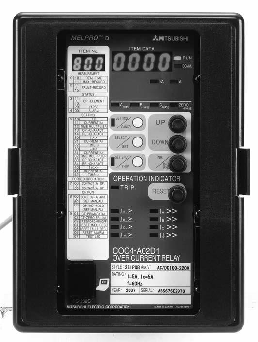
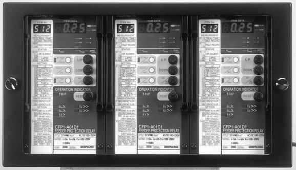
1 MITSUBISHI Numerical Protection Relay MELPRO TM -D Series MELPRO TM -D Mitsubishi ELectric corporation's PROtection relay for Distribution. Relays suitable for advanced network systems and strongly support power distribution automation.
2 2
3 Fundamental specification Optional specification Items to be informed Sample of ordering In case of COC4-A01D1 Remarks Type name Frequency Ratings Auxiliary power supply voltage Languages Communication function Parts 3
4 Conformity with IEC/JEC Protection for high voltage, extra high voltage power receiving and distribution Interconnection protection Motor protection Transformer protection Generator protection The high speed digital computation realizes the high accuracy operating characteristics never before possible. The operating characteristics are configured by the software, so that little deterioration and the stabilized operation can be realized. The digital computation is also applied to filter and then little deterioration of filter characteristics makes improving of reliability. The self-diagnosis function which monitors continuously the input, built-in power source and CPU is equipped. In the failures occurring of the relay, they can be detected immediately by the self-diagnosis function. Furthermore, dual output circuit makes possible to prevent the occurrence of misoperation due to the hardware failures. Adopt the structure to be resistant to the disturbances such as the electric surge and noise, the harmonics, the radio noise from the cellular phone, the temperature and the humidity. Always protect the electrical network and at the same time, detect the defects of relay and indicated them on the LED. X1 Dual system Prevent the misoperation due to the hardware failure. 4 The communication network system enables the data acquisition such as measurement value, operation status and setting value as well as the remote operation such as the setting changes from the central control system. Thereby, efficient operation and maintenance can be realized. By connecting PC with relay via the RS232C port located on the relay panel, local operation and monitoring are enabled as same as the remote operation and monitoring. Thereby, the maintenance work at site is strongly supported. Special HMI software (option) is needed for local operation and monitoring. Please refer to the specification table for each type of relay to confirm the capable of communication port and cards. In consideration of future communication network system variations and compatibility, communication features are installed in the relay using a replaceable card. Thereby, it is plenty flexible and extensible.


5 MELPRO TM -D The operating output contacts can be set by combing the outputs of the protection relay element using OR logic, thereby simplifying sequence design. Also, it is possible to reduce the cost of switchboard as reducing wiring works. I I X0 X3 I I X4 X5 Possible to measure the steady state of the relay input values (Current, Voltage, Power, Frequency, Power factor, Zero phase current and Zero phase voltage), thereby possible to support the energy management. Remark: Please note that measuring item is depended on the type of relay. Refer to the specification table of each relay type for the detail on this regards. In the event of system fault, input effective value and wave form data have been measured and stored at the time when one of the protection elements operates to issue an output signal. Data for up to five phenomena can be stored and displayed. Therefore, analyze of phenomena becomes easy. Upper Fig. : Image of waveform down loaded by the Direct PC HMI software The dimension of the panel cutting is the same as the prior MULTICAP series. Replacing from the existing one to this new type is possible easily without using adaptor. Also, as this relay has a high degree of compatibility with the existing relay, the design change of the existing system is minimized.except for some types of relay The draw-out unit mechanisms with automatic CT shorting is adopted, so that relay unit can be draw out without removing any parts or wirings. Thereby, it is possible to improve maintenance ease
6 6
7 NGR Resistance grounded neutral system C B C T 33W 66kV C B T R C T C T C T C T C B V T 27 U 50/51 51G 50/51 51G C B C T 50/51 51G U U 50/51 51G 87T d/ C B C T ZCT 3 C B T R Isolated neutral system C B V T 11kV/22kV 6.6kV/3.3kV G C B C T 33W 22kV/11kV C T C T C T C T 67G 50/51 V T ZCT C B C T 27 U 50/51 51G 50/51 51G U 3 87T d/ U U EVT G Network Incoming of extra high voltage Extra high voltage (secondary of transformer) High voltage (secondary of transformer) Device number 27 50/51 51G 50/51 51G T 50/51 51G 50/51 51G 50/ /51 67G G G COC3-A01D1/COC3-A03D1 1COC1-A02D1 3COC3-A01D1/COC3-A03D1 1COC1-A02D1 3COC3-A01D1/COC3-A03D1 1COC1-A02D1 3COC3-A01D1/COC3-A03D1 1COC1-A02D1 COC2-A01D1 MELPRO TM -D 1CBV3-A01D1 3CBV2-A01D1 1CBV2-A01D1 2CBV3-A01D1 CAC1-A01D2 COC3-A01D1/COC3-A03D1 CBV3-A01D1 CFP1-A01D1 CBV3-A01D1 CMP1-A02D1/CMP2-A02D2 CMP1-A01D1/CMP1-A01D2 COC4-A01D1 COC4-A02D1 COC4-A03D1 COC4-A01D1 COC4-A01D1 Remark 1: It is advisable to adopt the dual system or 2 out of 3 systems in order to improve the reliability of the important facilities. Remark 2: In case of not available an uninterruptible power source, please use AC/DC converter type B-T1 manufactured by MITSUBISHI ELECTRIC CORPORATION or commercially available uninterruptible power source (UPS) instead of using AC auxiliary power source such as derived from VT secondary circuit because of no guarantee against power interruption during system faults. S C CB : Circuit Breaker CT : Current Transformer EVT : Earthed type voltage Transformer M : Motor NGR : Neutral Grounded Resister SC : Static Condenser TR : Transformer VT : Voltage Transformer 7
8 8 ϕ
9 9
10 10
11 11
12 12
13 Current (Multiple of input current against setting value) Current (Multiple of input current against setting value) 13
14 14
15 15
16 16
17 17
18 18
19 19
20 20
21 21
22 22
23 23
24 24
25 25
26 26
27 27
28 k 28
29 29
30 Internal fault side Operating zone Through fault side 30
31 31
32 k k k k 32
33 k k k k 33
34 k k 34
35 35
36 36
37 37
38 38
39 39
40 k k 40
41 41
42 42
43 43
44 44
45 45
46 46
47 47
48 48
49 49
50 50
51 k k 51
52 52
53 53
54 54
55 55
56 56
57 57
58 58
59 59
60 As a way to improve the realiability of Protection system, MITSUBISHI ELECTRIC also provides customers the following products. Reduntant fault detection system COFIGURATION CONCEPT Ry 1 Ry 2 Ry 3 60
61 61
62 Initial status Start display Select ITEM No. Exit display status ITEM No. ITEM DATA SETTING CANSEL SELECT SET.END SET TRIP UP DOWN IND. IND. END OPERATION INDICATOR RESET SETTING CANSEL SELECT SET SET.END TRIP UP DOWN IND. IND. END OPERATION INDICATOR RESET SETTING CANSEL SELECT SET.END SET TRIP UP DOWN IND. IND. END OPERATION INDICATOR RESET SETTING CANSEL SELECT SET.END SET TRIP UP DOWN IND. IND. END OPERATION INDICATOR RESET Note: 1) In setting status, to change the group of ITEM No. ( ) UP DISPLAY DOWN (to display the last number of beginning group) Release Press and hold (1s) Release 2) Plural items can be set at one time. (same setting group only) Nothing displayed at windows of ITEM No. and ITEM DATA Start to display the ITEM No. and ITEM DATA by pushing IND/IND END Select ITEM No. by UP or DOWN, ITEM DATA displayed. Exit the display status by pushing IND/IND END Initial status Start setting Select ITEM No. Set ITEM No. Select setting value Admit setting value Make setting value effect ITEM ITEM ITEM ITEM ITEM ITEM ITEM ITEM DATA ITEM DATA ITEM DATA ITEM DATA ITEM DATA ITEM DATA ITEM DATA No. No. No. No. No. No. No. SETTING SETTING SETTING UP UP UP CANSEL CANSEL CANSEL SETTING UP CANSEL SETTING UP CANSEL SETTING UP CANSEL SETTING UP CANSEL SELECT SELECT SELECT DOWN DOWN DOWN SET SET SET SELECT DOWN SET SELECT DOWN SET SELECT DOWN SET SELECT DOWN SET SET.END IND. SET.END IND. SET.END IND. SET.END IND. SET.END IND. SET.END IND. SET.END IND. TRIP IND. END TRIP IND. END TRIP IND. END TRIP IND. END TRIP IND. END TRIP IND. END TRIP IND. END OPERATION INDICATOR OPERATION INDICATOR OPERATION INDICATOR OPERATION INDICATOR OPERATION INDICATOR OPERATION INDICATOR OPERATION INDICATOR RESET Nothing displayed at windows of ITEM No. and ITEM DATA ITEM No. RESET ITEM DATA RESET Select ITEM No. by UP or DOWN. (ITEM No. LED blinking) ITEM No. RESET ITEM DATA RESET Select setting value by UP or DOWN. (ITEM DATA LED blinking) ITEM No. ITEM DATA RESET Set the selected setting value. Please note that selected setting value is not effective at this moment. RESET All selected setting value are effective by this operation. SETTING SETTING UP SETTING CANSEL UP SETTING SETTING CANSEL UP UP CANSEL CANSEL SELECT SELECT DOWN DOWN SET SET SET.END TRIP IND. IND. END SET.END TRIP IND. IND. END Please repeat the same operation in case of two or more items setting (The above is applicable only for the same group classified with the same number of top digit.) All indications are changed to turning off condition. 62
63 63
64 MITSUBISHI Numerical Protection Relay MELPRO TM -D Series CAUTION HEAD OFFICE : 7-3 MARUNOUCHI 2-CHOME, CHIYODA-KU TOKYO, , JAPAN TO PREVENT IT FROM THE RISK OF DAMAGE AND MAL FUNCTION, BE SURE TO READ OPERATING AND MAINTENANCE (SERVICING) INSTRUCTIONS BEFORE USING. We are waiting your technical contacts by FAX. ATTN. Protective relay technical service FAX NO. JAPAN SE-E840-E( )ROS "MELPRO" is a trademark of the Mitsubishi Electric Corporation. This printed matter has been published June Please note that specifications are subject to change without notice.
Request Ensure that this Instruction Manual is delivered to the end users and the maintenance manager.
 Request Ensure that this Instruction Manual is delivered to the end users and the maintenance manager. 1 -C - Safety section - This Safety section should be read before starting any work on the relay.
Request Ensure that this Instruction Manual is delivered to the end users and the maintenance manager.
 Request Ensure that this Instruction Manual is delivered to the end users and the maintenance manager. 1 -F - Safety section - This Safety section should be read before starting any work on the relay.
Protection of Electrical Networks. Christophe Prévé
 Protection of Electrical Networks Christophe Prévé This Page Intentionally Left Blank Protection of Electrical Networks This Page Intentionally Left Blank Protection of Electrical Networks Christophe Prévé
NERC Protection Coordination Webinar Series June 9, Phil Tatro Jon Gardell
 Power Plant and Transmission System Protection Coordination GSU Phase Overcurrent (51T), GSU Ground Overcurrent (51TG), and Breaker Failure (50BF) Protection NERC Protection Coordination Webinar Series
T/3000 T/3000. Substation Maintenance and Commissioning Test Equipment
 T/3000 Substation Maintenance and Commissioning Test Equipment MULTI FUNCTION SYSTEM FOR TESTING SUBSTATION EQUIPMENT SUCH AS: CURRENT, VOLTAGE AND POWER TRANSFORMERS, ALL TYPE OF PROTECTION RELAYS, ENERGY
Transformer protection IED RET 670
 Gunnar Stranne Transformer protection IED RET 670 Santiago Septiembre 5, 2006 1 Transformer protection IED RET670 2 Introduction features and applications Differential protection functions Restricted Earth
Texas Reliability Entity Event Analysis. Event: May 8, 2011 Loss of Multiple Elements Category 1a Event
 Texas Reliability Entity Event Analysis Event: May 8, 2011 Loss of Multiple Elements Category 1a Event Texas Reliability Entity July 2011 Page 1 of 10 Table of Contents Executive Summary... 3 I. Event
RETROFITTING. Motor Protection Relay. Two mountings are available, Flush Rear Connection (EDPAR) or Projecting Rear Connection (SDPAR).
 or Projecting Rear Connection (SDPAR).") RETROFITTING Motor Protection Relay NPM800R (R2 case) and NPM800RE (R3 case) are dedicated to the refurbishment of 7000 series (R2 and R3 cases) of CEE relays providing the protection of medium voltage
RETROFITTING Motor Protection Relay NPM800R (R2 case) and NPM800RE (R3 case) are dedicated to the refurbishment of 7000 series (R2 and R3 cases) of CEE relays providing the protection of medium voltage
Module 9. Fault Type Form 4.X RELIABILITY ACCOUNTABILITY
 Module 9 Fault Type Form 4.X 1 M9 Fault Type The descriptor of the fault, if any, associated with each Automatic Outage of an Element. 1. No fault 2. Phase-to-phase fault (P-P) 3. Single phase-to-ground
Single Line Diagram of Substations
 Single Line Diagram of Substations Substations Electric power is produced at the power generating stations, which are generally located far away from the load centers. High voltage transmission lines are
Module 10. Initiation Code RELIABILITY ACCOUNTABILITY
 Module 10 Initiation Code 1 M10 Initiation Code This is not the Initiating cause code The Outage Initiation Codes describe where an Automatic Outage was initiated on the power system. Element-Initiated
EARTH FAULT PROTECTION VIS-A-VIS GENERATOR GROUNDING SYSTEM
 EARTH FAULT PROTECTION VIS-A-VIS GENERATOR GROUNDING SYSTEM BY MR. H. C. MEHTA AT 1 ST INDIA DOBLE PROTECTION AND AUTOMATION CONFERENCE, NOV 2008 POWER-LINKER Wisdom is not Virtue but Necessity hcmehta@powerlinker.org
200ADM-P. Current Injection System with Phase Shift A 3.000s 2.000A 50.00Hz 0.0. Features
 CT ratio Power Harmonics ac+dc 200ADM-P Current Injection System with Phase Shift Features 0-200A output current True RMS metering with 1 cycle capture Variable auxiliary AC voltage/current output with
SPECIFICATION FOR OVERCURRENT RELAYS
 SPECIFICATION FOR OVERCURRENT RELAYS 1/9 1. Procedure A manufacturer willing to classify an overcurrent relay according to this specification should provide: A complete file providing a clear, unambiguous
REB500 TESTING PROCEDURES
 Activate HMI 500/REBWIN ver 6.10 or 7.xx. The following screen will appear. Check out the Read Only box & type the password System. Click ok. Connect the black communication cable from the Com port until
2015 Relay School Bus Protection Mike Kockott March, 2015
 2015 Relay School Bus Protection Mike Kockott March, 2015 History of Bus Protection Circulating current differential (1900s) High impedance differential (1940s) Percentage restrained differential (1960s)
Unit 2. Single Line Diagram of Substations
 Unit 2 Single Line Diagram of Substations Substations Electric power is produced at the power generating stations, which are generally located far away from the load centers. High voltage transmission
N. TEST TEST DESCRIPTION
 Multi function system for testing substation equipment such as: current, voltage and power transformers, all type of protection relays, energy meters and transducers Primary injection testing capabilities
1000Vac distribution system for Signalling System applications
 1000Vac distribution system for Signalling System applications System for Transforming, Carrying and Distributing 1000Vac electric energy for technological equipment and devices along the railway line.
Addendum to Instructions for Installation, Operation and Maintenance of Digitrip 3000 Protective Relays
 Dual-Source Power Supply Addendum to I.B. 17555 Addendum to Instructions for Installation, Operation and Maintenance of Digitrip 3000 Protective Relays Table of Contents Page 1.0 Introduction...1 2.0 General
APPLICATION: The heart of the system is a DSR 100 Digital Static Regulator used in conjunction with standard SCR based rectifier bridges.
 APPLICATION: Basler Electric offers a New Line of digitally controlled brush (static) or brushless excitation systems designed for use with existing Hydro, Gas as well as Diesel driven generators requiring
Modern transformer relays include a comprehensive set of protective elements to protect transformers from faults and abnormal operating conditions
 1 Transmission transformers are important links in the bulk power system. They allow transfer of power from generation centers, up to the high-voltage grid, and to bulk electric substations for distribution
Self-Contained Type HSVC (High Side Voltage Control) or PSS (Power System Stabilizer)
 or PSS (Power System Stabilizer)") Self-Contained Type (High Side Voltage Control) or PSS (Power System Stabilizer) Power System Voltage Vr(PU) 0.5 800 1000 1200 1400 1600 Transmission Power Pr(MW) Self-Contained Type or PSS unit unit Easy
Self-Contained Type (High Side Voltage Control) or PSS (Power System Stabilizer) Power System Voltage Vr(PU) 0.5 800 1000 1200 1400 1600 Transmission Power Pr(MW) Self-Contained Type or PSS unit unit Easy
CONFIGURATION HANDBOOK
 VOLTAGE PRESENCE RELAY FOR CAPACITIVE DIVIDER, TRANSFORMER, RESISTIVE BRIDGE AC+DC CONFIGURATION HANDBOOK RPT23 LOREME 12, rue des Potiers d'etain Actipole BORNY - B.P. 35014-57071 METZ CEDEX 3 Phone 03.87.76.32.51
Earth Fault Relay EFSPL-1A/5A
 Earth Fault Relay EFSPL-1A/5A IEEE DEVICES CODE-50N Features Static Device Compact, Reliable with Aesthetic Value Rugged, Robust and Tropicalised design Consistent repeat accuracy Wide Current Operating
www. ElectricalPartManuals. com Transformer Differential Relay MD32T Transformer Differential Relay
 Transformer Differential Relay The MD3T Transformer Differential Relay is a member of Cooper Power Systems Edison line of microprocessor based protective relays. The MD3T relay offers the following functions:
889 Advanced Generator Protection Technical Note
 GE Grid Solutions 8 Series 889 Advanced Generator Protection Technical Note GE Publication Number: GET-20056 Copyright 2017 GE Multilin Inc. Overview The Multilin 889 is part of the 8 Series platform that
N. TEST TEST DESCRIPTION
 Multi function system for testing substation equipment such as: current, voltage and power transformers, over-current protection relays, energy meters and transducers Primary injection testing capabilities
RS Pro ENGLISH. Datasheet
 Datasheet Article No: 136-5385 Digital AC Ammeter, 48x96, 1Phase, 1 or 5 Amps AC, Supply 40-300V ac/dc 136-5387 Digital AC Ammeter, 96x96, 1Phase, 1 or 5 Amps AC, Supply 40-300V ac/dc 136-5388 Digital
NPRG860 NPRG870 REGULATION. Automatic Synchronizer for Generator
 REGULATION Automatic Synchronizer for Generator NPRG860 & NPRG870 perform synchronization and paralleling of generators with electrical network. NPRG860 features a speed adjustment function. NPRG870 adds
A Special Ferro-resonance Phenomena on 3-phase 66kV VT-generation of 20Hz zero sequence continuous voltage
 A Special Ferro-resonance Phenomena on 3-phase 66kV VT-generation of Hz zero sequence continuous voltage S. Nishiwaki, T. Nakamura, Y.Miyazaki Abstract When an one line grounding fault in a transmission
Technical Datasheet. True RMS Digital Protection Relay. Voltage Protection Relay
 Technical Datasheet RELAY-1 RISHABH k V RESET True RMS Digital Protection Relay RELAY-2 TEST True RMS Measurement RISH Relay V is used to protect against Over Voltage, Under Voltage, Phase Sequence detection,
SPAE 010, 011 High Impedance Protection Relay
 SPAE 010, 011 High Impedance Protection Relay User s manual and Technical description f n = 50/60 Hz U n = 50 / 100 / 200 V 2 5 U REF > SPAE 010 0.8 U aux 0.6 1.0 RESET OK x 80... 265 V ~ _ 0.4 U > U n
E N G I N E E R I N G M A N U A L
 1 1 1.0 PURPOSE The purpose of this document is to define policy and provide engineering guidelines for the AP operating companies (Monongahela Power Company, The Potomac Edison Company, and West Penn
POWER QUALITY A N D Y O U R B U S I N E S S THE CENTRE FOR ENERGY ADVANCEMENT THROUGH TECHNOLOGICAL I NNOVATION
 POWER QUALITY A N D Y O U R B U S I N E S S A SUMMARY OF THE POWER QUALITY REPORT PUBLISHED BY THE CENTRE FOR ENERGY ADVANCEMENT THROUGH TECHNOLOGICAL I NNOVATION H YDRO ONE NETWORKS INC SEPTEMBER 2014
Phase and neutral overcurrent protection
 Phase and neutral overcurrent protection Page 1 ssued June 1999 Changed since July 1998 Data subject to change without notice (SE970165) Features Two-phase or three-phase time-overcurrent and earth fault
Power systems Protection course
 Al-Balqa Applied University Power systems Protection course Department of Electrical Energy Engineering 1 Part 5 Relays 2 3 Relay Is a device which receive a signal from the power system thought CT and
Power Regenerative Converter, THYFREC CV240S
 Development of New Products Power Regenerative Converter, THYFREC CV240S Harmonic restraint, Power regeneration, 120 conduction, Power factor improvement, Common converter system, Environment compatibility
Appendix S: PROTECTION ALTERNATIVES FOR VARIOUS GENERATOR CONFIGURATIONS
 Appendix S: PROTECTION ALTERNATIVES FOR VARIOUS GENERATOR CONFIGURATIONS S1. Standard Interconnection Methods with Typical Circuit Configuration for Single or Multiple Units Note: The protection requirements
Relion 605 series Self-Powered Feeder Protection REJ603 Product Guide
 Relion 605 series Relion 605 series Self-Powered Feeder Protection Product Guide Contents 1 Description...3 2 Protection functions...3 3 Application...4 4 Self-supervision...4 5 Inputs and outputs...4
Technical Datasheet. True RMS Digital Protection Relay. Line Monitoring Relay
 Technical Datasheet RELAY-1 RELAY-2 k V Hz RESET ABH TEST True RMS Measurement True RMS Digital Protection V/Hz is used to protect against Over Voltage, Under Voltage, Phase Unbalance, Phase Sequence detection,
T 1000 PLUS. Secondary Injection Relay Test Set. Designed for testing relays and transducers
 Secondary Injection Relay Test Set Designed for testing relays and transducers Microprocessor controlled With phase angle shifter Frequency generator Test results and settings are saved into local memory
ASHIDA Numerical 3OC + 1EF Protection Relay
 PROTH. ERR L5 PKP FAULT DT REC LOCK BF L6 L7 CLOSE TRIP ADR 241B Protection Features : 4 Element (3 Phase + EF + Sensitive EF) Over current IDMT/DMT with instant trip. Programmable (Non- Volatile) Setting
CDV 22, 62. Voltage Controlled Overcurrent Relay GRID PROTECTION
 PROTECTION CDV 22, 62 Voltage Controlled Overcurrent Relay CDV22 relay is used for overload and fault protection for ac generators when the sustained short circuit current is less than the full load current.
Protection Basics Presented by John S. Levine, P.E. Levine Lectronics and Lectric, Inc GE Consumer & Industrial Multilin
 Protection Basics Presented by John S. Levine, P.E. Levine Lectronics and Lectric, Inc. 770 565-1556 John@L-3.com 1 Protection Fundamentals By John Levine 2 Introductions Tools Outline Enervista Launchpad
Capstone Turbine Corporation Nordhoff Street Chatsworth CA USA Phone: (818) Fax: (818) Web:
 Fax: (818) Web:") Phone: (818) 734-5300 Fax: (818) 734-5320 Web: www.capstoneturbine.com Technical Reference Capstone MicroTurbine Electrical Installation 410009 Rev F (October 2013) Page 1 of 31 Capstone Turbine Corporation
Phone: (818) 734-5300 Fax: (818) 734-5320 Web: www.capstoneturbine.com Technical Reference Capstone MicroTurbine Electrical Installation 410009 Rev F (October 2013) Page 1 of 31 Capstone Turbine Corporation
RS Pro ENGLISH. Datasheet
 Datasheet ENGLISH Article No: 136-5390 Digital AC Ammeter, 48x96, 3Phase, 1 or 5 Amps AC, Supply 40-300V ac/dc 136-5391 Digital AC Ammeter, 96x96, 3Phase, 1 or 5 Amps AC, Supply 40-300V ac/dc 136-5393
S1-3: New and re-discovered theories and practices in relay protection
 (Cheboksary, September 9-13, 27) S1-3: New and re-discovered theories and practices in relay protection Practical experience from multiterminal line differential protection installations Z. GAJIĆ, I. BRNČIĆ,
presentation contents application advantages
 presentation contents page presentation protection functional and connection schemes other connection schemes connection characteristics 9 installation 0 commissioning ordering information Sepam 00 is
Stabilized Differential Relay SPAD 346. Product Guide
 Issued: July 1998 Status: Updated Version: D/21.03.2006 Data subject to change without notice Features Integrated three-phase differential relay, three-phase overcurrent relay and multiconfigurable earth-fault
Ior DIGITAL LEAKAGE CLAMP TESTER MCL-400IR INSTRUCTION MANUAL
 Ior DIGITAL LEAKAGE CLAMP TESTER MCL-400IR INSTRUCTION MANUAL Thank you very much for selecting our model MCL-400IR Ior Leakage Clamp Tester. Before use the instrument, read this instruction manual completely
TD 1000 PLUS. Secondary Injection Relay Test Set. Designed for testing relays and transducers
 Secondary Injection Relay Test Set Designed for testing relays and transducers Two current outputs to test differential relays Convertible current and voltage generator With phase angle shifter Frequency
SECTION LOW VOLTAGE ACTIVE HARMONIC FILTER SYSTEM NEMA 1 ENCLOSED
 SECTION 16280 LOW VOLTAGE ACTIVE HARMONIC FILTER SYSTEM NEMA 1 ENCLOSED PART 1 - GENERAL 1.1 SUMMARY This specification defines the requirements for active harmonic filter systems in order to meet IEEE-519-2014
Time over/underfrequency relay with protection assemblies
 Time over/underfrequency relay with protection assemblies RXFK 2H and RAFK 509 009-BEN Page 1 Issued June 1999 Changed since July 1998 Data subject to change without notice (SE970104) (SE970108) Features
NPRG860 & NPRG870 perform synchronization and paralleling of generators with electrical network. NPRG860 features a speed adjustment function.
 REGULATION AUTOMATIC SYNCHRONIZER for GENERATOR NPRG860 & NPRG870 perform synchronization and paralleling of generators with electrical network. NPRG860 features a speed adjustment function. NPRG870 adds
PD300. Transformer, generator and motor protection Data sheet
 PD300 Transformer, generator and motor protection Data sheet DSE_PD300_eng_AO No part of this publication may be reproduced by whatever means without the prior written permission of Ingeteam T&D. One of
Power System Protection Manual
 Power System Protection Manual Note: This manual is in the formative stage. Not all the experiments have been covered here though they are operational in the laboratory. When the full manual is ready,
DRTS-6. DRTS-6 has been designed to test: DRTS-6. Advanced Protection Relay Test Set and Measurement System
 DRTS-6 Advanced Protection Relay Test Set and Measurement System MULTI-TASKING EQUIPMENT DESIGNED FOR TESTING PROTECTION RELAYS, ENERGY METERS, TRANSDUCERS POWERFUL AND LIGHTWEIGHT HIGH ACCURACY: BETTER
Earth fault protection for isolated neutral systems with frequency converters
 Earth fault protection for isolated neutral systems with frequency converters Page Issued June 999 Changed since July 998 Data subject to change without notice (SE97089) Features Earth fault and flash-over
Advanced Test Equipment Rentals ATEC (2832)
") Established 1981 Advanced Test Equipment Rentals www.atecorp.com 800-404-ATEC (2832) The toolbox for substation 3-phase testing Three currents and four voltages Stand-alone functionality Rugged and reliable
Established 1981 Advanced Test Equipment Rentals www.atecorp.com 800-404-ATEC (2832) The toolbox for substation 3-phase testing Three currents and four voltages Stand-alone functionality Rugged and reliable
Protective Relays Digitrip 3000
 New Information Technical Data Effective: May 1999 Page 1 Applications Provides reliable 3-phase and ground overcurrent protection for all voltage levels. Primary feeder circuit protection Primary transformer
High-set undervoltage stage with definitetime. or inverse definite minimum time (IDMT) characteristic. Low-set undervoltage stage with definitetime
 characteristic. Low-set undervoltage stage with definitetime") Issued: 5.06.999 Status: 5.06.999 Version: B/09..00 Data subject to change without notice Features Overvoltage and undervoltage protection Single- or three-phase operation High-set overvoltage stage with
Issued: 5.06.999 Status: 5.06.999 Version: B/09..00 Data subject to change without notice Features Overvoltage and undervoltage protection Single- or three-phase operation High-set overvoltage stage with
SPAD 346 C Stabilized differential relay
 SPAD 346 C Stabilized differential relay Stabilized Differential Relay Type SPAD 346 C Features Integrated three-phase differential relay, three-phase overcurrent relay and multiconfigurable earth-fault
STATIC EARTH FAULT RELAY
 EARTH FAULT (EFR) EFSPL SERIES IEEE DEVICES CODE-50N Features ŸStatic Device ŸCompact, Reliable with Aesthetic Value ŸRugged, Robust and Tropicalised design ŸConsistent repeat accuracy ŸWide Current Operating
Optimizing HV Capacitor-Bank Design Protection & Testing
 Optimizing HV Capacitor-Bank Design Protection & Testing Benton Vandiver III ABB Inc. 71st Annual Conference for Protective Relay Engineers Texas A&M University Introduction Shunt Capacitor Bank Considerations
Overcurrent Elements
 Exercise Objectives Hands-On Relay Testing Session Overcurrent Elements After completing this exercise, you should be able to do the following: Identify overcurrent element settings. Determine effective
Table of Contents. Introduction... 1
 Table of Contents Introduction... 1 1 Connection Impact Assessment Initial Review... 2 1.1 Facility Design Overview... 2 1.1.1 Single Line Diagram ( SLD )... 2 1.1.2 Point of Disconnection - Safety...
BU: EPBP GPG: DIN Rail Products Devices for the permanent control of insulation on supply lines for medical locations ISOLTESTER-DIG-RZ/RS/PLUS
 INSTRUCTION MANUAL BU: EPBP GPG: DIN Rail Products Devices for the permanent control of insulation on supply lines for medical locations ISOLTESTER-DIG-RZ/RS/PLUS 1/23 More information than that reported
ASHIDA Numerical OC/EF Protection Relay
 ASHIDA Numerical OC/EF Protection Relay Features: 4 Element (3 Phase + EF) over current IDMT with instant trip. Back - lit LCD display for settings. Display of fault current. / Load current. Selection
ECP GROUND-MOUNTED SWITCHGEAR WITH PROTECTION RELAYS COMMISSIONING PROCEDURE
 ENGINEERING COMMISSIONING PROCEDURE ECP 11-0512 GROUND-MOUNTED SWITCHGEAR WITH PROTECTION RELAYS COMMISSIONING PROCEDURE Network(s): Summary: EPN, LPN, SPN This procedure details the testing and commissioning
Remotes Case 2&3 Form REINDEER Cases 2&3 -Connection Impact Assessment (CIA) Application
 Application") General Application Information Remotes Case 2&3 Form REINDEER Cases 2&3 -Connection Impact Assessment (CIA) Application Hydro One Remote Communities Inc. Lori.Rice@hydroone.com 1-807-474-2828 This Application
General Application Information Remotes Case 2&3 Form REINDEER Cases 2&3 -Connection Impact Assessment (CIA) Application Hydro One Remote Communities Inc. Lori.Rice@hydroone.com 1-807-474-2828 This Application
Device circuit breakers Selective power distribution: branch out, individual adaptation, modular extension
 Power & Signal Quality TRABTECH Device circuit breakers Selective power distribution: branch out, individual adaptation, modular extension Interference-free mains supply and signal transmission A constant
SVERKER 900 Relay and Substation Test System
 SVERKER 900 The toolbox for substation 3-phase testing Three currents and four voltages Stand-alone functionality Rugged and reliable for field use Generation of 900 V and 105 A in single phase mode Secondary
thepower to protect the power to protect i-gard LITERATURE Low and medium voltage
 thepower to protect i-gard LITERATURE Low and medium voltage distribution systems Arc Flash Hazards and High Resistance Grounding Grounding of Standby and Emergency Power Systems Neutral Grounding Resistors
Power Quality Basics. Presented by. Scott Peele PE
 Power Quality Basics Presented by Scott Peele PE PQ Basics Terms and Definitions Surge, Sag, Swell, Momentary, etc. Measurements Causes of Events Possible Mitigation PQ Tool Questions Power Quality Measurement
Overvoltage and undervoltage. Dr Audih 1
 Overvoltage and undervoltage Dr Audih 1 A Overvoltage is defined as an increase in the r.m.s. value of the voltage up to a level between 1.1 pu to 1.8 pu at power frequency for periods ranging from a half
LCE-MBP-400. User Manual. TDI Transistor Devices Inc. 85 Horsehill Road, Cedar Knolls, NJ USA Phone: Fax:
 LCE-MBP-400 User Manual TDI Transistor Devices Inc. 85 Horsehill Road, Cedar Knolls, NJ 07834 USA Phone: 973.267.1900 Fax: 973.267.2047 Page 2 of 11 TABLE OF CONTENTS 1. Introduction 1.1 Description 3
StacoDVR-4 Digital Voltage Regulator Electromechanical three-phase kVA
 StacoDVR-4 Digital Voltage Regulator Electromechanical three-phase 30-1250kVA StacoDVR-4 Digital Voltage Regulator Electromechanical three-phase 30-1250kVA This voltage regulators are available for different
sw rev. 55B DEVICE FOR THE PERMANENT CONTROL OF INSULATION ON THE SUPPLY LINES IN MEDICAL PRACTICE PLACES INSTALLATIONS
 INSTRUCTIONS MANUAL IM831-U v0.92 HRI-R40W sw rev. 55B DEVICE FOR THE PERMANENT CONTROL OF INSULATION ON THE SUPPLY LINES IN MEDICAL PRACTICE PLACES INSTALLATIONS INDEX: GENERAL TYPES ACESSORIES AND OPTIONS
HV / MV / LV electrical network quality analyzers Class A. Communication port: local, modem, integrated Ethernet, multi-point
 2010 MAP Range HV / MV / LV electrical network quality analyzers Class A > Network quality Analyzers PRODUCT ADVANTAGES COMPLIANT with the EN 61000-4-30 standard, Class A DETECTION of the fault LOCATION
LED Driver Compact fixed output
 Driver LC 5/3/35/4W 6/7/8/9mA fixc C ADV ADVANCED series Product description Fixed output built-in LED Driver Constant current LED Driver Output current 6, 7, 8 or 9 ma Max. output power 6.5, 31, 36 or
PHASED OUT. LED Driver Compact fixed output. Driver LCI 20W 350mA 900mA TOP C TOP series
 EL Product description Fixed output built-in LED Driver Constant current LED Driver Output current settable 30 900 ma Max. output power 20 W Nominal life-time up to 100,000 h For luminaires of protection
SPECIFICATION, CONTROLS AND ACCESSORIES
 AS440 Automatic Voltage Regulator (AVR) SPECIFICATION, CONTROLS AND ACCESSORIES English Original Instructions A043Y697 (Issue 2) Table of Contents 1. DESCRIPTION... 1 2. SPECIFICATION... 3 3. CONTROLS...
Extensive LV cable network. Figure 1: Simplified SLD of the transformer and associated LV network
 Copyright 2017 ABB. All rights reserved. 1. Introduction Many distribution networks around the world have limited earth-fault current by a resistor located in the LV winding neutral point of for example
Installation and Operating Instructions. Power IT Power Factor Controller RVC
 Installation and Operating Instructions Power IT Power Factor Controller RVC Table of contents Page 1. Read this first... 3 About this Instruction Manual... 3 Safety... 3 Electromagnetic compatibility...
Catastrophic Relay Misoperations and Successful Relay Operation
 Catastrophic Relay Misoperations and Successful Relay Operation Steve Turner (Beckwith Electric Co., Inc.) Introduction This paper provides detailed technical analysis of several catastrophic relay misoperations
Spänningsstabilisatorer Voltage Stabilisers. General information
 Spänningsstabilisatorer Voltage Stabilisers Allmänt General information INTRODUCTION & TECHNOLOGY IMPORTANCE OF VOLTAGE S The increase of voltage sensitive equipment has determined a continuous request
LED Driver Linear / area fixed output
 Driver LC 53W 5-35mA flexc lp ANCED series Product description Built-in constant current LED Driver New version DC operating with EL marking Adjustable output current between 5 and 35 ma Max. output power
PHASED OUT. LED Driver Compact fixed output. Driver LCI 10W 150mA 400mA TOP C TOP series. Product description
 Product description EL Fixed output built-in LED Driver Constant current LED Driver Output current settable 15 4 ma Max. output power W Nominal life-time up to, h For luminaires of protection class I and
DPF-MAC Auto power factor controller
 Digital Electric& Electronics System DPF-MAC Auto power factor controller MULTI POWER FACTOR AUTOMATIC MULTI POWER FACTOR AUTOMATIC Introduction DPF-MAC increases usage efficiency by controlling the power
Research on State Estimation and Information Processing Method for Intelligent Substation
 , pp.89-93 http://dx.doi.org/10.14257/astl.2015.83.17 Research on State Estimation and Information Processing Method for Intelligent Substation Tongwei Yu 1, Xingchao Yang 2 1 Electric Power Research Institute,
Uninterruptible Power System (UPS) 20 to 320 kva
 20 to 320 kva") Large-capacity Uninterruptible Power System (UPS) 20 to 320 kva All IGBT type UPS 7000F Series REC 82-5 Fuji's UPS for today's computerized On-line support for all applications Data communication devices
Large-capacity Uninterruptible Power System (UPS) 20 to 320 kva All IGBT type UPS 7000F Series REC 82-5 Fuji's UPS for today's computerized On-line support for all applications Data communication devices
Advanced Test Equipment Rentals ATEC (2832) Lightning Surge Simulator LSS-F02.
 Lightning Surge Simulator LSS-F02.") Lightning Surge Simulator Established 1981 Advanced Test Equipment Rentals www.atecorp.com 800-404-ATEC (2832) LSS-F02 www.noiseken.com Conforming to IEC61000-4-5 ed2 Standard LSS-F02 series A simulator
Lightning Surge Simulator Established 1981 Advanced Test Equipment Rentals www.atecorp.com 800-404-ATEC (2832) LSS-F02 www.noiseken.com Conforming to IEC61000-4-5 ed2 Standard LSS-F02 series A simulator
Computer-14d - xx - 144a
 POWER FACTOR REGULATOR Computer-14d - xx - 144a INSTRUCTION MANUAL ( M 981 602 / 98B ) (c) CIRCUTOR S.A. -------- POWER FACTOR REGULATOR COMPUTER- 14d --------- Page 2 1.- POWER FACTOR REGULATORS COMPUTER-14d-144a
DRTS 66 The new generation of advanced test equipments for Relays, Energy meters, Transducers and Power quality meters
 The new generation of advanced test equipments for Relays, Energy meters, Transducers and Power quality meters Testing all relay technologies: electromechanical, solid state, numerical and IEC61850 Manual
T 1000 PLUS Secondary Injection Relay Test Set
 Secondary Injection Relay Test Set Designed for testing relays and transducers Microprocessor controlled With phase angle shifter Frequency generator Test results and settings are saved into local memory
LED Driver Compact fixed output. Udriver LC 25/30/35/40W 600/700/800/900mA fixc SC ADV ADVANCED series
 Udriver LC 5/3/35/4W 6/7/8/9mA fixc SC ADV ADVANCED series Product description Fixed output LED Driver Can be either used build-in or independent with clip-on strain-relief (see accessory) Constant current
UProtection Requirements. Ufor a Large scale Wind Park. Shyam Musunuri Siemens Energy
 UProtection Requirements Ufor a Large scale Wind Park Shyam Musunuri Siemens Energy Abstract: In the past wind power plants typically had a small power rating when compared to the strength of the connected
VI 3 - i TABLE OF CONTENTS
 VI 3 - i TABLE OF CONTENTS 3 PROJECT SPECIFIC DATA... 1 3.1 DEFINITIONS... 1 3.1.1 Design Data, High and Medium Voltage... 1 3.1.2 Design Data, Low Voltage Equipment... 2 3.1.3 Phase Relationship... 3
PHASED OUT. LED Driver Compact fixed output. Driver LCI 10W 350mA 900mA TOP C TOP series
 EL Product description Fixed output built-in LED Driver Constant current LED Driver Output current settable 35 9 ma Max. output power W Nominal life-time up to, h For luminaires of protection class I and